EP3505760A1 - Liquid supply system - Google Patents
Liquid supply system Download PDFInfo
- Publication number
- EP3505760A1 EP3505760A1 EP17843487.4A EP17843487A EP3505760A1 EP 3505760 A1 EP3505760 A1 EP 3505760A1 EP 17843487 A EP17843487 A EP 17843487A EP 3505760 A1 EP3505760 A1 EP 3505760A1
- Authority
- EP
- European Patent Office
- Prior art keywords
- bellows
- shaft
- cylindrical member
- supply system
- liquid supply
- Prior art date
- Legal status (The legal status is an assumption and is not a legal conclusion. Google has not performed a legal analysis and makes no representation as to the accuracy of the status listed.)
- Withdrawn
Links
- 239000007788 liquid Substances 0.000 title claims abstract description 75
- 239000012530 fluid Substances 0.000 claims description 15
- 238000007789 sealing Methods 0.000 description 29
- 238000001816 cooling Methods 0.000 description 10
- 229910052751 metal Inorganic materials 0.000 description 9
- 239000002184 metal Substances 0.000 description 9
- 230000002093 peripheral effect Effects 0.000 description 6
- 239000004810 polytetrafluoroethylene Substances 0.000 description 5
- 229920001343 polytetrafluoroethylene Polymers 0.000 description 5
- 239000011248 coating agent Substances 0.000 description 4
- 238000000576 coating method Methods 0.000 description 4
- 230000001050 lubricating effect Effects 0.000 description 4
- 238000010586 diagram Methods 0.000 description 3
- 239000007789 gas Substances 0.000 description 3
- 230000004048 modification Effects 0.000 description 3
- 238000012986 modification Methods 0.000 description 3
- 239000011347 resin Substances 0.000 description 3
- 229920005989 resin Polymers 0.000 description 3
- XKRFYHLGVUSROY-UHFFFAOYSA-N Argon Chemical compound [Ar] XKRFYHLGVUSROY-UHFFFAOYSA-N 0.000 description 2
- IJGRMHOSHXDMSA-UHFFFAOYSA-N Atomic nitrogen Chemical compound N#N IJGRMHOSHXDMSA-UHFFFAOYSA-N 0.000 description 2
- 239000000463 material Substances 0.000 description 2
- 238000000034 method Methods 0.000 description 2
- 230000010349 pulsation Effects 0.000 description 2
- 238000005086 pumping Methods 0.000 description 2
- BQCADISMDOOEFD-UHFFFAOYSA-N Silver Chemical compound [Ag] BQCADISMDOOEFD-UHFFFAOYSA-N 0.000 description 1
- 238000005299 abrasion Methods 0.000 description 1
- 229910052786 argon Inorganic materials 0.000 description 1
- 230000008602 contraction Effects 0.000 description 1
- 230000000694 effects Effects 0.000 description 1
- 239000013013 elastic material Substances 0.000 description 1
- 230000020169 heat generation Effects 0.000 description 1
- 239000001307 helium Substances 0.000 description 1
- 229910052734 helium Inorganic materials 0.000 description 1
- SWQJXJOGLNCZEY-UHFFFAOYSA-N helium atom Chemical compound [He] SWQJXJOGLNCZEY-UHFFFAOYSA-N 0.000 description 1
- 229910052757 nitrogen Inorganic materials 0.000 description 1
- 238000007747 plating Methods 0.000 description 1
- 230000003252 repetitive effect Effects 0.000 description 1
- 238000000926 separation method Methods 0.000 description 1
- 230000035939 shock Effects 0.000 description 1
- 229910052709 silver Inorganic materials 0.000 description 1
- 239000004332 silver Substances 0.000 description 1
- 238000009834 vaporization Methods 0.000 description 1
- 230000008016 vaporization Effects 0.000 description 1
Images




Classifications
-
- F—MECHANICAL ENGINEERING; LIGHTING; HEATING; WEAPONS; BLASTING
- F04—POSITIVE - DISPLACEMENT MACHINES FOR LIQUIDS; PUMPS FOR LIQUIDS OR ELASTIC FLUIDS
- F04B—POSITIVE-DISPLACEMENT MACHINES FOR LIQUIDS; PUMPS
- F04B43/00—Machines, pumps, or pumping installations having flexible working members
- F04B43/08—Machines, pumps, or pumping installations having flexible working members having tubular flexible members
- F04B43/084—Machines, pumps, or pumping installations having flexible working members having tubular flexible members the tubular member being deformed by stretching or distortion
-
- F—MECHANICAL ENGINEERING; LIGHTING; HEATING; WEAPONS; BLASTING
- F04—POSITIVE - DISPLACEMENT MACHINES FOR LIQUIDS; PUMPS FOR LIQUIDS OR ELASTIC FLUIDS
- F04B—POSITIVE-DISPLACEMENT MACHINES FOR LIQUIDS; PUMPS
- F04B43/00—Machines, pumps, or pumping installations having flexible working members
- F04B43/08—Machines, pumps, or pumping installations having flexible working members having tubular flexible members
- F04B43/088—Machines, pumps, or pumping installations having flexible working members having tubular flexible members with two or more tubular flexible members in series
-
- F—MECHANICAL ENGINEERING; LIGHTING; HEATING; WEAPONS; BLASTING
- F04—POSITIVE - DISPLACEMENT MACHINES FOR LIQUIDS; PUMPS FOR LIQUIDS OR ELASTIC FLUIDS
- F04B—POSITIVE-DISPLACEMENT MACHINES FOR LIQUIDS; PUMPS
- F04B43/00—Machines, pumps, or pumping installations having flexible working members
- F04B43/08—Machines, pumps, or pumping installations having flexible working members having tubular flexible members
-
- F—MECHANICAL ENGINEERING; LIGHTING; HEATING; WEAPONS; BLASTING
- F04—POSITIVE - DISPLACEMENT MACHINES FOR LIQUIDS; PUMPS FOR LIQUIDS OR ELASTIC FLUIDS
- F04B—POSITIVE-DISPLACEMENT MACHINES FOR LIQUIDS; PUMPS
- F04B53/00—Component parts, details or accessories not provided for in, or of interest apart from, groups F04B1/00 - F04B23/00 or F04B39/00 - F04B47/00
-
- F—MECHANICAL ENGINEERING; LIGHTING; HEATING; WEAPONS; BLASTING
- F05—INDEXING SCHEMES RELATING TO ENGINES OR PUMPS IN VARIOUS SUBCLASSES OF CLASSES F01-F04
- F05B—INDEXING SCHEME RELATING TO WIND, SPRING, WEIGHT, INERTIA OR LIKE MOTORS, TO MACHINES OR ENGINES FOR LIQUIDS COVERED BY SUBCLASSES F03B, F03D AND F03G
- F05B2210/00—Working fluid
- F05B2210/10—Kind or type
- F05B2210/11—Kind or type liquid, i.e. incompressible
Definitions
- the present invention relates to a liquid supply system which includes a bellows.
- a technique is known in which a bellows is used in order to form a sealed space between a shaft which performs reciprocating motion and a cylindrical member through which the shaft is inserted.
- One end of the bellows is generally fixed to the shaft and the other end is fixed to the cylindrical member.
- This configuration has an advantage because it includes no sliding portion which can be a cause of sliding abrasion and heat generation by sliding. Therefore a liquid supply system to circulate ultra-low temperature liquid, for example, generally uses a bellows to form a sealed structure (see PTL 1).
- the present invention uses the following means.
- a liquid supply system of one aspect of the present invention is a liquid supply system having a container, a shaft which extending from the outside to the inside of the container and configured to perform reciprocating motion by a driving source, a cylindrical member which is disposed in the container, through which the shaft is inserted, a first bellows which is fixed to the shaft and configured to expand and contract in accordance with the reciprocating motion of the shaft, and a second bellows which is configured to expand and contract in accordance with the reciprocating motion of the shaft, the second bellows and the first bellows forming a pump chamber therebetween and the second bellows having an outer diameter smaller than an outer diameter of the first bellows.
- One end of the second bellows is fixed to one of the shaft and the cylindrical member, and the other end of the second bellows is positioned to the other of the shaft and the cylindrical member being allowed to move in a circumferential direction.
- one end of the second bellows is fixed to one of the shaft and the cylindrical member, but the other end is positioned to the other of the shaft and the cylindrical member being allowed to move in a circumferential direction.
- a seal portion may be disposed on the other end of the second bellows the seal portion being configured to have a contact with the other of the shaft and the cylindrical member to seal fluid and having a larger area than an effective area of the second bellows.
- the liquid supply system may further include a third bellows which is configured to expand and contract in accordance with the reciprocating motion of the shaft, the third bellows forming a sealed space between the cylindrical member and the second bellows and the third bellows, and a part of liquid transferred from the pump chamber is supplied to the sealed space.
- a third bellows which is configured to expand and contract in accordance with the reciprocating motion of the shaft, the third bellows forming a sealed space between the cylindrical member and the second bellows and the third bellows, and a part of liquid transferred from the pump chamber is supplied to the sealed space.
- One end of the third bellows may be fixed to one of the shaft and the cylindrical member, and the other end of the third bellows is positioned to the other of the shaft and the cylindrical member being allowed to move in the circumferential direction.
- the generation of the twisting in the bellows can be suppressed.
- the liquid supply system 100 according to this embodiment described bellow supplies ultra-low temperature liquid L to a cooling target apparatus 500 having a resin container 510 and a superconducting coil 520 inside the resin container 510.
- the ultra-low temperature liquid L include liquid nitrogen, liquid helium and liquid argon.
- the liquid supply system 100 has a container which contains the ultra-low temperature liquid L (first container 110), a second container 120 which is disposed in the liquid L contained in the first container 110, and a first bellows 130 which is disposed to enter into the second container 120.
- first container 110 contains the ultra-low temperature liquid L
- second container 120 which is disposed in the liquid L contained in the first container 110
- first bellows 130 which is disposed to enter into the second container 120.
- an external space of the first bellows 130 forms a first pump chamber P1.
- An internal space of the first bellows 130 which is a sealed space, forms a second pump chamber P2.
- the first bellows 130 is made of metal. Instead of containing liquid, the internal space of the first container 110 may be a vacuum.
- a passage for returning liquid back to the first container 110 (later mentioned as a return passage K2) and an inlet for drawing the liquid into the second container 120 (later mentioned as a first inlet 121 and second inlet 123) may be connected.
- the second container 120 has a first inlet 121 which draws the liquid L in the first container 110 into the first pump chamber P1 and a first outlet 122 which delivers the drawn liquid L from the first pump chamber P1 to a supply passage (supply pipe) K1 which is connected to the outside of the system.
- the second container 120 further has a second inlet 123 which draws the liquid L in the first container 110 into the second pump chamber P2 and a second outlet 124 which delivers the drawn liquid L from the second pump chamber P2 to the supply passage K1.
- the first inlet 121 and the second inlet 123 has one way valves 121a and 123a, respectively, and the first outlet 122 and the second outlet 124 has one way valves 122a and 124a, respectively.
- a metal shaft 150 which is configured to perform reciprocating motion by a linear actuator 140 (driving source), is disposed from the outside to the inside of the first container 110.
- the end of the shaft 150 is fixed to the end of the first bellows 130.
- the first bellows 130 is capable of expanding and contracting as the shaft 150 performs the reciprocating motion.
- a cushioning structure 160 is provided around the shaft 150 to cushion pressure fluctuation (pulsation) of the liquid L supplied via the supply passage K1.
- the cushioning structure 160 is disposed in the first container 110, and includes a cylindrical member 161 which is a cylinder (may be a circular cylinder) through which the shaft 150 is inserted, and a second bellows 200 and a third bellows 300 which are disposed at the lower end and upper end of the cylindrical member 161, respectively.
- the second bellows 200 and the third bellows 300 are both made of metal.
- the first bellows 130 is fixed to the shaft 150 at a position that is most distant from the driving source (linear actuator 140) among the first bellows 130, the second bellows 200 and the third bellows 300.
- the second bellows 200 is configured to expand and contract in accordance with the reciprocating motion of the shaft 150, and the first bellows 130 and the second bellows 200 are configured to form a sealed space between them.
- the sealed space corresponds to the above mentioned second pump chamber P2.
- the outer diameter of the second bellows 200 is smaller than the outer diameter of the first bellows 130.
- the third bellows 300 is configured to expand and contract in accordance with the reciprocating motion of the shaft 150 and the outer diameter of the third bellows 300 is smaller than the outer diameter of the first bellows 130.
- the sealed space R is formed by the cylindrical member 161, the second bellows 200 and the third bellows 300. A layer of the liquid L and a layer of the gas G generated by vaporization of the liquid L are formed in the sealed space R.
- a branch passage K3, which branches from the supply passage K1, is disposed so as to be connected to the sealed space R.
- the pressure of the liquid L, which is supplied via the supply passage K1 is also applied in the sealed space R, and as a result, the gas inside the sealed space R functions as a damper, and absorbs the shock caused by the fluctuation (pulsation) of the pressure of the liquid L supplied via the supply passage K1.
- the sealed space R is therefore a damper chamber.
- the cushioning structure 160 has, near the third bellows 300, a safety valve 162, which releases the internal pressure of the sealed space R to the outside when the pressure becomes a predetermined value or more. This enables the pressure inside the sealed space R to be released when the pressure becomes abnormally high due to, for example, increase in an amount of vaporized gas G in the sealed space R. This prevents an extreme increase in internal pressure which would cause breakage of the cylindrical member 161, the second bellows 200 and the third bellows 300, thus such breakage can be suppressed.
- the second bellows 200 is disposed on the upper end side of the first bellows 130, as described above, so that the space inside the first bellows 130 is a sealed space.
- the sealed space forms the second pump chamber P2, as mentioned above.
- the above configuration allows the liquid L to be delivered from the second pump chamber P2 to the supply passage K1 via the second outlet 124 and the liquid L to be drawn into the first pump chamber P1 via the first inlet 121 when the first bellows 130 contracts.
- the liquid L is drawn into the second pump chamber P2 via the second inlet 123 and delivered from the first pump chamber P1 to the supply passage K1 via the first outlet 122 when the first bellows 130 expands.
- the liquid L is delivered to the supply passage K1 whether the bellows 130 expands or contracts.
- the liquid supply system 100 supplies the liquid L to the cooling target apparatus 500 via the supply passage K1 through the repetitive expansion and contraction operations of the first bellows 130.
- the return passage (return pipe) K2 which is provided to connect the liquid supply system 100 and the cooling target apparatus 500, is configured to return as much liquid L as supplied to the cooling target apparatus 500 to the liquid supply system 100.
- a cooling apparatus 400 for cooling the liquid L to an ultra-low temperature state is disposed in the supply passage K1. The configuration enables the liquid L, which was cooled to the ultra-low temperature by the cooling apparatus 400, to circulate between the liquid supply system 100 and the cooling target apparatus 500.
- the shaft 150 and the cylindrical member 161 of the liquid supply system 100 according to the embodiment may be slightly rotated relative to each other due to a mechanism of the system. This may generate torsion buckling, particularly in the second bellows 200 and the third bellows 300, of which diameters are small.
- the liquid supply system 100 according to the embodiment has a structure to suppress the generation of torsion buckling in the second bellows 200 and the third bellows 300.
- one end of the second bellows 200 is fixed to one of the shaft 150 and the cylindrical member 161.
- the other end of the second bellows 200 is positioned at the other of the shaft 150 and the cylindrical member 161 being allowed to move in the circumferential direction. This suppresses the generation of twisting in the second bellows 200 even when the shaft 150 and the cylindrical member 161 rotate relative to each other.
- one end of the third bellows 300 is fixed to one of the shaft 150 and the cylindrical member 161.
- the other end of the third bellows 300 is positioned to the other of the shaft 150 and the cylindrical member 161 being allowed to move in the circumferential direction. This suppresses twisting of third bellows 300 even when the shaft 150 and the cylindrical member 161 rotate relative to each other.
- the liquid supply system 100 of this embodiment the generation of twisting in the second bellows 200 and the third bellows 300 is prevented. This suppresses the generation of torsion buckling in the second bellows 200 and the third bellows 300 and a decrease in the life of the bellows due to fatigue. Further, breakage of the bellows which can be cause of a leak of the liquid can be prevented, thus, the pump chamber can be protected from being exposed to high temperature.
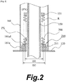
- FIG. 2 is a schematic cross-sectional view depicting the sealing structure according to Example 1.
- the shaft 150 of the sealing structure of Example 1 has an outward flange portion 151 and one end of the second bellows 200 is fixed to it.
- a metal valve body 210 To the other end of the second bellows 200 is fixed a metal valve body 210.
- the cylindrical member 161 has an inward flange portion 161a.
- the end face of the inward flange portion 161a on the sealed space R side is a valve seat 161a1.
- an annular protrusion 211 is disposed as a seal portion. The valve is closed when the annular protrusion 211 is set on the valve seat 161a1.
- one end of the second bellows 200 of Example 1 is fixed to the shaft 150 and the other end of the second bellows 200 has the valve body 210 disposed on it, which is configured to slide on the valve seat 161a1 in the rotating direction.
- the other end of the second bellows 200 is positioned in the state being allowed to move in the circumferential direction with respect to the cylindrical member 161. This suppresses the twisting of the second bellows 200 even when the shaft 150 and the cylindrical member 161 rotate relative to each other.
- the surface of the valve body 210 or the valve seat 161a1 may be subjected to lubricating treatment such as PTFE coating so that the valve body 210 and the valve seat 161a1 slide with each other more easily.
- the shape of the portion which separate the inside and outside of the second bellows 200 is a circle
- the shape of the tip of the annular protrusion 211, which is a seal portion contacting the valve seat 161a1 in the valve body 210 is a circle. It is designed such that the diameter D2 of the circle of the seal portion is larger than the effective diameter D1 of the second bellows 200. In other words, the area of the seal portion is larger than the effective area of the second bellows 200, hence stable sealing performance can be achieved by the valve body 210. This aspect will be described in more detail below.
- the inside of the second bellows 200 constitutes the second pump chamber P2 and the outside of the second bellows 200 constitutes a damper chamber (sealed space R).
- the fluid pressure PX in the second pump chamber P2 fluctuates because of pumping, and the maximum pressure thereof is the delivery pressure of the liquid supply system.
- the fluid pressure PY in the damper chamber is kept approximately at the delivery pressure because the pressure of the fluid supplied from the first pump chamber P1 and that from the second pump chamber P2 acts thereon, that is, PY ⁇ PX always holds.
- the pressing force of the valve body 210 to the valve seat 161a1 depends on the elastic repulsive force by the second bellows 200 and the differential pressure between the fluid pressure in the damper chamber and the fluid pressure in the second pump chamber P2. Therefore if D2 > D1, then the valve body 210 can make close contact with the valve seat 161a1 with higher certainty, even under a PY > PX condition.
- the valve body 210 moves away from the valve seat 161a1 and the valve opens, then the liquid L enters from the second pump chamber P2 to the dumper chamber. Thereby breakage of the first bellows 130 and the second bellows 200 can be prevented. Although the pumping performance may decrease temporarily when the liquid L enters the dumper chamber, the performance of the liquid supply system 100 is not affected.
- Example 2 shows a specific example of the sealing structure which includes the second bellows 200.
- Fig. 3 is a schematic cross-sectional view depicting the sealing structure according to Example 2.
- the cylindrical member 161 of the sealing structure of Example 2 has an inward flange portion 161b and one end of the second bellows 200 is fixed to it.
- an annular member 230 which is a metal plate, is fixed to one end of the second bellows 200, and the annular member 230 is fixed to the inward flange portion 161b.
- To the other end of the second bellows 200 is fixed a metal valve body 220.
- the shaft 150 has an outward flange portion 152.
- the end face of the outward flange portion 152, on the second pump chamber P2 side, is a valve seat 152a.
- an annular protrusion 221 is disposed as a seal portion. The valve is closed when the annular protrusion 221 is set on the valve seat 152a.
- one end of the second bellows 200 of Example 2 is fixed to the cylindrical member 161 and the other end of the second bellows 200 has the valve body 220 disposed on it, which is configured to slide on the valve seat 152a in the rotating direction.
- the other end of the second bellows 200 is positioned to the shaft 150 in a state being allowed to move in the circumferential direction. This suppresses the twisting of the second bellows 200 even when the shaft 150 and the cylindrical member 161 rotate relative to each other.
- the surface of the valve body 220 or the valve seat 161a1 may be subjected to lubricating treatment such as PTFE coating so that the valve body 220 and the valve seat 152a slide with each other more easily.
- the shape of the portion which separates the inside and the outside of the second bellows 200 is a circle
- the shape of the tip of the annular protrusion 221, which is a seal portion contacting the valve seat 152a in the valve body 220 is a circle. It is designed such that the diameter D4 of the circle of the seal portion is larger than the effective diameter D3 of the second bellows 200. Thereby a stable sealing performance can be achieved by the valve body 220, as described in Example 1.
- Example 3 shows a specific example of the sealing structure which includes the second bellows 200.
- Fig. 4 is a schematic cross-sectional view depicting the sealing structure according to Example 3.
- the shaft 150 of the sealing structure of Example 3 has an outward flange portion 153 and one end of the second bellows 200 is fixed to it.
- a metal seal holding member 240 To the other end of the second bellows 200 is fixed a metal seal holding member 240.
- the seal holding member 240 has a shape which can be obtained by forming an annular groove 241 on an outer peripheral surface of an annular member having a rectangular cross-section.
- a seal ring 250 which performs the self-sealing function, is installed in the annular groove 241.
- the portion of the annular groove 241 which makes a close contact with the seal ring 250 functions as the seal portion in this embodiment. This portion makes a contact with the seal ring 250 on the cylindrical member 161 side, thus the fluid is sealed.
- the seal ring 250 is not limited to the V ring, but can be various seal rings which perform a self-sealing function, such as a U ring having a U-shaped cross-section and a D ring having a D-shaped cross-section.
- the seal ring 250 may be made of thin metal or the like, instead of resins such as PTFE and PI.
- An inward flange portion 161c is disposed in the cylindrical member 161.
- the inward flange portion 161c and the seal holding member 240 are not fixed to each other.
- the seal holding member 240 is configured to be slidable on the inward flange portion 161c.
- the seal ring 250 and the inner peripheral surface of the cylindrical member 161 are slidable with each other.
- one end of the second bellows 200 of Example 3 is fixed to the shaft 150 and the other end of the second bellows 200 has the seal holding member 240 disposed on it, which is configured to slide on the inward flange portion 161c of the cylindrical member 161 in the rotating direction. Further, the seal ring 250 and the inner peripheral surface of the cylindrical member 161 are slidable with each other. In other words, the other end of the second bellows 200 is positioned to the cylindrical member 161 in a state being allowed to move in the circumferential direction. This suppresses the twisting of the second bellows 200 even when the shaft 150 and the cylindrical member 161 rotate relative to each other.
- the surface of the seal ring 250 or the inner peripheral surface of the cylindrical member 161 may be subjected to lubricating treatment such as PTFE coating and silver plating so that the seal ring 250 and the inner peripheral surface of the cylindrical member 161 slide with each other more easily.
- the shape of the portion which separates the inside and outside of the second bellows 200 is a circle. It is designed such that the inner diameter D6 of the annular groove 241 formed in the seal holding member 240 is larger than the effective diameter D5 of the second bellows 200. Thereby separation of the seal holding member 240 from the inward flange portion 161c can be suppressed due to the same mechanism as described in Example 1 as to the configuration D2 > D1.
- One end of the second bellows 200 of Example 3 is fixed to the shaft 150 and the other end of the second bellows 200 is positioned to the cylindrical member 161 in the state being allowed to move in the circumferential direction.
- one end of the second bellows 200 may be fixed to the cylindrical member 161.
- a seal holding member configured to hold a seal ring having a self-sealing function may be disposed on the other end of the second bellows 200, and the seal holding member may be configured to slide on the shaft 150.
- Example 4 shows a specific example of the sealing structure which includes a third bellows 300.
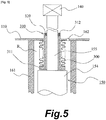
- Fig. 5 is a schematic cross-sectional view depicting the sealing structure according to Example 4.
- One end of the third bellows 300 of the sealing structure of Example 4 is fixed to the cylindrical member 161.
- the cylindrical member 161 and one end of the third bellows 300 are directly fixed to the first container 110, respectively, whereby one end of the third bellows 300 is fixed to the cylindrical member 161.
- a metal seal holding member 310 is fixed to the other end of the third bellows 300.
- the seal holding member 310 has a cylindrical member, and one end of the cylindrical member has an outward flange portion 311 and the other end of the cylindrical member has an annular groove 312 disposed in an inner peripheral surface thereof.
- the other end of the third bellows 300 is fixed to the outward flange portion 311 in the seal holding member 310.
- a seal ring 320 made of a rubber-like elastic material is installed in the annular groove 312 of the seal holding member 310.
- the seal ring 320 is an O ring having a circle-shaped cross-section.
- the seal ring 320 is not limited to an O ring, but may be various seal rings such as a square ring having a rectangular cross-section.
- a rubber material may be used for the seal ring 320 because it is in an environment exposed to air.
- the shaft 150 of the sealing structure Example 4 has a large diameter portion 154 located nearer to the inside of the first container 110 and a small diameter portion 155 located nearer to the outside of the first container 110 (nearer to the air).
- the small diameter portion 155 is inserted through the cylindrical seal holding member 310.
- the seal holding member 310 is disposed so that a step surface between the large diameter portion 154 and the small diameter portion 155 faces the end face of the outward flange portion 311. There is a gap between the step surface and the end face of the outward flange portion 311.
- the step surface and the outward flange portion 311 are configured to slide with each other when they make a contact with each other.
- the seal holding member 310 is positioned with respect to the shaft 150 by constraining force of the seal ring 320 to the shaft 150 (smaller diameter portion 155). This constraining force allows the seal holding member 310 to perform reciprocating motion together with the shaft 150 when the shaft 150 performs reciprocating motion, whereby the third bellows 300 expands and contracts. Further, when the shaft 150 rotates relative to the cylindrical member 161, the shaft 150 and the seal ring 320 are slidable with each other.
- one end of the third bellows 300 of Example 4 is fixed to the cylindrical member 161.
- the seal ring 320 and the shaft 150 are slidable in the rotating direction as described above, hence the seal holding member 310 disposed on the other end of the third bellows 300 is rotatable around the shaft 150.
- the other end of the third bellows 300 is positioned in a state being allowed to move in the circumferential direction around the shaft 150. This suppresses the twisting of the third bellows 300 even when the shaft 150 and the cylindrical member 161 rotate relative to each other.
- the surface of the seal ring 320 or on the shaft 150 may be subjected to lubricating treatment such as PTFE coating so that the seal ring 320 and the shaft 150 slide with each other more easily.
- Fig. 6 is a schematic configuration diagram depicting the operating state of the liquid supply system according to a modification of the embodiments.
- the basic configuration of the modification is the same as that of the liquid supply system illustrated in Fig. 1 , hence the same elements as Fig. 1 are denoted with the same reference signs, and descriptions thereof will be omitted.
- the liquid supply system 100 illustrated in Fig. 6 has a fourth bellows 135 in the second container 120, which is fixed to the shaft 150 and expands and contracts in accordance with the reciprocating motion of the shaft 150, similarly to the first bellows 130.
- a first pump chamber P1 is formed between the outside of the fourth bellows 135 and the second container 120 and a second pump chamber P2 is formed between the outside of the first bellows 130, the second container 120 and the second bellows 200.
- the inside of the first container 110 of the liquid supply system 100 may be a vacuum without containing liquid.
- a return passage K2 for returning the fluid back to the first container 110 and an inlet (first inlet 121 and second inlet 123) for drawing the liquid into the second container 120 are connected.
Landscapes
- Engineering & Computer Science (AREA)
- Mechanical Engineering (AREA)
- General Engineering & Computer Science (AREA)
- Reciprocating Pumps (AREA)
- Sealing Devices (AREA)
Abstract
Description
- The present invention relates to a liquid supply system which includes a bellows.
- A technique is known in which a bellows is used in order to form a sealed space between a shaft which performs reciprocating motion and a cylindrical member through which the shaft is inserted. One end of the bellows is generally fixed to the shaft and the other end is fixed to the cylindrical member. This configuration has an advantage because it includes no sliding portion which can be a cause of sliding abrasion and heat generation by sliding. Therefore a liquid supply system to circulate ultra-low temperature liquid, for example, generally uses a bellows to form a sealed structure (see PTL 1).
- There is no particular issue as long as the shaft and the cylindrical member do not rotate relative to each other. However, the shaft and the cylindrical member may slightly rotate relative to each other due to the mechanism of the system. This may cause the bellows to be twisted, and then torsion buckling may be generated. Such torsion buckling is more likely to be generated in a bellows having a smaller diameter. If the bellows expands and contracts in a state where torsion buckling is generated, stress may be locally concentrated, and the product lifetime of the bellows may be shortened due to fatigue.
- [PTL 1]
WO 2012/124363 - It is an object of the present invention to provide a liquid supply system in which generation of twisting of a bellows is suppressed.
- To achieve the above object, the present invention uses the following means.
- A liquid supply system of one aspect of the present invention is a liquid supply system having
a container,
a shaft which extending from the outside to the inside of the container and configured to perform reciprocating motion by a driving source,
a cylindrical member which is disposed in the container, through which the shaft is inserted,
a first bellows which is fixed to the shaft and configured to expand and contract in accordance with the reciprocating motion of the shaft, and
a second bellows which is configured to expand and contract in accordance with the reciprocating motion of the shaft, the second bellows and the first bellows forming a pump chamber therebetween and the second bellows having an outer diameter smaller than an outer diameter of the first bellows. - One end of the second bellows is fixed to one of the shaft and the cylindrical member, and the other end of the second bellows is positioned to the other of the shaft and the cylindrical member being allowed to move in a circumferential direction.
- According to the one aspect, one end of the second bellows is fixed to one of the shaft and the cylindrical member, but the other end is positioned to the other of the shaft and the cylindrical member being allowed to move in a circumferential direction. This suppresses the generation of twisting in the second bellows which would be followed by breakage of the second bellows even when the shaft and the cylindrical member rotate relative to each other. Thus, leakage of fluid in the pump chamber can be suppressed.
- A seal portion may be disposed on the other end of the second bellows the seal portion being configured to have a contact with the other of the shaft and the cylindrical member to seal fluid and having a larger area than an effective area of the second bellows.
- In a state where fluid pressure on the opposite side of the pump chamber across the seal portion is higher than fluid pressure inside the pump chamber, a valve body in the seal portion is kept in close contact with a valve sheet in the seal portion, hence stable sealing performance can be achieved. By contrast, in a state where the fluid pressure on the opposite side of the pump chamber across the seal portion is lower than the fluid pressure inside the pump chamber, the contacting state in the seal portion becomes out of contact state by the pressure acting thereon, and the liquid inside the pump chamber flows to a region on the opposite side of the pump chamber across the seal portion, hence pressure can be released, and excessive pressure can be suppressed from acting on the second bellows.
- The liquid supply system may further include a third bellows which is configured to expand and contract in accordance with the reciprocating motion of the shaft, the third bellows forming a sealed space between the cylindrical member and the second bellows and the third bellows, and a part of liquid transferred from the pump chamber is supplied to the sealed space.
- This makes the region on the opposite side of the pump chamber across the seal portion a sealed space, and fluid discharged from the pump is supplied to the sealed space. This enables the pressure in the sealed space to be not less than the pressure in the pump chamber, thus twisting of the second bellows can be suppressed and the sealed state can be kept.
- One end of the third bellows may be fixed to one of the shaft and the cylindrical member, and the other end of the third bellows is positioned to the other of the shaft and the cylindrical member being allowed to move in the circumferential direction.
- This suppresses twisting of both the second bellows and the third bellows and breakage of the bellows. Thus the sealed space formed by the cylindrical member, the second bellows and the third bellows can be kept in a sealed state with certainty.
- Each of the above configurations may be combined and used where possible.
- As described above, according to the present invention, the generation of the twisting in the bellows can be suppressed.
-
-
Fig. 1 is a schematic configuration diagram depicting the operating state of the liquid supply system according to an embodiment. -
Fig. 2 is a schematic cross-sectional view depicting the sealing structure according to Example 1. -
Fig. 3 is a schematic cross-sectional view depicting the sealing structure according to Example 2. -
Fig. 4 is a schematic cross-sectional view depicting the sealing structure according to Example 3. -
Fig. 5 is a schematic cross-sectional view depicting the sealing structure according to Example 4. -
Fig. 6 is a schematic configuration diagram depicting the operating state of the liquid supply system according to a modification of the embodiments. - An embodiment of the present invention will be described based on examples with reference to the drawings. Dimensions, materials, shapes and relative positions of the components described in the examples are not intended to restrict the scope of the invention unless otherwise specified.
- A general configuration and operation method of a liquid supply system 100 (circulator) according to this embodiment will be described with reference to
Fig. 1 . Theliquid supply system 100 according to this embodiment described bellow supplies ultra-low temperature liquid L to acooling target apparatus 500 having aresin container 510 and asuperconducting coil 520 inside theresin container 510. Examples of the ultra-low temperature liquid L include liquid nitrogen, liquid helium and liquid argon. - The
liquid supply system 100 has a container which contains the ultra-low temperature liquid L (first container 110), asecond container 120 which is disposed in the liquid L contained in thefirst container 110, and afirst bellows 130 which is disposed to enter into thesecond container 120. Within thesecond container 120, an external space of thefirst bellows 130 forms a first pump chamber P1. An internal space of thefirst bellows 130, which is a sealed space, forms a second pump chamber P2. Thefirst bellows 130 is made of metal. Instead of containing liquid, the internal space of thefirst container 110 may be a vacuum. In such a configuration, a passage for returning liquid back to the first container 110 (later mentioned as a return passage K2) and an inlet for drawing the liquid into the second container 120 (later mentioned as afirst inlet 121 and second inlet 123) may be connected. - The
second container 120 has afirst inlet 121 which draws the liquid L in thefirst container 110 into the first pump chamber P1 and afirst outlet 122 which delivers the drawn liquid L from the first pump chamber P1 to a supply passage (supply pipe) K1 which is connected to the outside of the system. Thesecond container 120 further has asecond inlet 123 which draws the liquid L in thefirst container 110 into the second pump chamber P2 and asecond outlet 124 which delivers the drawn liquid L from the second pump chamber P2 to the supply passage K1. Thefirst inlet 121 and thesecond inlet 123 has oneway valves first outlet 122 and thesecond outlet 124 has oneway valves 122a and 124a, respectively. - A
metal shaft 150, which is configured to perform reciprocating motion by a linear actuator 140 (driving source), is disposed from the outside to the inside of thefirst container 110. The end of theshaft 150 is fixed to the end of the first bellows 130. Thereby the first bellows 130 is capable of expanding and contracting as theshaft 150 performs the reciprocating motion. - A
cushioning structure 160 is provided around theshaft 150 to cushion pressure fluctuation (pulsation) of the liquid L supplied via the supply passage K1. Thecushioning structure 160 is disposed in thefirst container 110, and includes acylindrical member 161 which is a cylinder (may be a circular cylinder) through which theshaft 150 is inserted, and a second bellows 200 and a third bellows 300 which are disposed at the lower end and upper end of thecylindrical member 161, respectively. The second bellows 200 and thethird bellows 300 are both made of metal. The first bellows 130 is fixed to theshaft 150 at a position that is most distant from the driving source (linear actuator 140) among the first bellows 130, the second bellows 200 and the third bellows 300. - The second bellows 200 is configured to expand and contract in accordance with the reciprocating motion of the
shaft 150, and thefirst bellows 130 and the second bellows 200 are configured to form a sealed space between them. The sealed space corresponds to the above mentioned second pump chamber P2. The outer diameter of the second bellows 200 is smaller than the outer diameter of the first bellows 130. - The third bellows 300 is configured to expand and contract in accordance with the reciprocating motion of the
shaft 150 and the outer diameter of the third bellows 300 is smaller than the outer diameter of the first bellows 130. The sealed space R is formed by thecylindrical member 161, the second bellows 200 and the third bellows 300. A layer of the liquid L and a layer of the gas G generated by vaporization of the liquid L are formed in the sealed space R. - A branch passage K3, which branches from the supply passage K1, is disposed so as to be connected to the sealed space R. Thereby the pressure of the liquid L, which is supplied via the supply passage K1, is also applied in the sealed space R, and as a result, the gas inside the sealed space R functions as a damper, and absorbs the shock caused by the fluctuation (pulsation) of the pressure of the liquid L supplied via the supply passage K1. The sealed space R is therefore a damper chamber.
- The
cushioning structure 160 has, near the third bellows 300, asafety valve 162, which releases the internal pressure of the sealed space R to the outside when the pressure becomes a predetermined value or more. This enables the pressure inside the sealed space R to be released when the pressure becomes abnormally high due to, for example, increase in an amount of vaporized gas G in the sealed space R. This prevents an extreme increase in internal pressure which would cause breakage of thecylindrical member 161, the second bellows 200 and the third bellows 300, thus such breakage can be suppressed. - In this embodiment, the second bellows 200 is disposed on the upper end side of the first bellows 130, as described above, so that the space inside the first bellows 130 is a sealed space. The sealed space forms the second pump chamber P2, as mentioned above.
- The above configuration allows the liquid L to be delivered from the second pump chamber P2 to the supply passage K1 via the
second outlet 124 and the liquid L to be drawn into the first pump chamber P1 via thefirst inlet 121 when thefirst bellows 130 contracts. The liquid L is drawn into the second pump chamber P2 via thesecond inlet 123 and delivered from the first pump chamber P1 to the supply passage K1 via thefirst outlet 122 when the first bellows 130 expands. Thus, the liquid L is delivered to the supply passage K1 whether thebellows 130 expands or contracts. - As described above, the
liquid supply system 100 according to the embodiment supplies the liquid L to thecooling target apparatus 500 via the supply passage K1 through the repetitive expansion and contraction operations of the first bellows 130. The return passage (return pipe) K2, which is provided to connect theliquid supply system 100 and thecooling target apparatus 500, is configured to return as much liquid L as supplied to thecooling target apparatus 500 to theliquid supply system 100. Acooling apparatus 400 for cooling the liquid L to an ultra-low temperature state is disposed in the supply passage K1. The configuration enables the liquid L, which was cooled to the ultra-low temperature by thecooling apparatus 400, to circulate between theliquid supply system 100 and thecooling target apparatus 500. - The
shaft 150 and thecylindrical member 161 of theliquid supply system 100 according to the embodiment may be slightly rotated relative to each other due to a mechanism of the system. This may generate torsion buckling, particularly in the second bellows 200 and the third bellows 300, of which diameters are small. Theliquid supply system 100 according to the embodiment has a structure to suppress the generation of torsion buckling in the second bellows 200 and the third bellows 300. - Specifically, one end of the second bellows 200 according to the embodiment is fixed to one of the
shaft 150 and thecylindrical member 161. The other end of the second bellows 200, on the other hand, is positioned at the other of theshaft 150 and thecylindrical member 161 being allowed to move in the circumferential direction. This suppresses the generation of twisting in the second bellows 200 even when theshaft 150 and thecylindrical member 161 rotate relative to each other. - Further, one end of the
third bellows 300 according to this embodiment is fixed to one of theshaft 150 and thecylindrical member 161. The other end of the third bellows 300, on the other hand, is positioned to the other of theshaft 150 and thecylindrical member 161 being allowed to move in the circumferential direction. This suppresses twisting ofthird bellows 300 even when theshaft 150 and thecylindrical member 161 rotate relative to each other. - As described above, the
liquid supply system 100 of this embodiment, the generation of twisting in the second bellows 200 and the third bellows 300 is prevented. This suppresses the generation of torsion buckling in the second bellows 200 and thethird bellows 300 and a decrease in the life of the bellows due to fatigue. Further, breakage of the bellows which can be cause of a leak of the liquid can be prevented, thus, the pump chamber can be protected from being exposed to high temperature. - Specific examples of the sealing structure using each bellows will be described below.
- A sealing structure according to Example 1 will be described with reference to
Fig. 2 . A specific example of a sealing structure which includes the second bellows 200 will be shown in Example 1.Fig. 2 is a schematic cross-sectional view depicting the sealing structure according to Example 1. - The
shaft 150 of the sealing structure of Example 1 has anoutward flange portion 151 and one end of the second bellows 200 is fixed to it. To the other end of the second bellows 200 is fixed ametal valve body 210. Thecylindrical member 161 has aninward flange portion 161a. The end face of theinward flange portion 161a on the sealed space R side is a valve seat 161a1. On the valve seat 161a1 side of thevalve body 210, anannular protrusion 211 is disposed as a seal portion. The valve is closed when theannular protrusion 211 is set on the valve seat 161a1. - As described above, one end of the second bellows 200 of Example 1 is fixed to the
shaft 150 and the other end of the second bellows 200 has thevalve body 210 disposed on it, which is configured to slide on the valve seat 161a1 in the rotating direction. In other words, the other end of the second bellows 200 is positioned in the state being allowed to move in the circumferential direction with respect to thecylindrical member 161. This suppresses the twisting of the second bellows 200 even when theshaft 150 and thecylindrical member 161 rotate relative to each other. The surface of thevalve body 210 or the valve seat 161a1 may be subjected to lubricating treatment such as PTFE coating so that thevalve body 210 and the valve seat 161a1 slide with each other more easily. - In the portion where the other end of the second bellows 200 and the
valve body 210 are fixed, the shape of the portion which separate the inside and outside of the second bellows 200 is a circle, and the shape of the tip of theannular protrusion 211, which is a seal portion contacting the valve seat 161a1 in thevalve body 210, is a circle. It is designed such that the diameter D2 of the circle of the seal portion is larger than the effective diameter D1 of the second bellows 200. In other words, the area of the seal portion is larger than the effective area of the second bellows 200, hence stable sealing performance can be achieved by thevalve body 210. This aspect will be described in more detail below. - The inside of the second bellows 200 constitutes the second pump chamber P2 and the outside of the second bellows 200 constitutes a damper chamber (sealed space R). The fluid pressure PX in the second pump chamber P2 fluctuates because of pumping, and the maximum pressure thereof is the delivery pressure of the liquid supply system. The fluid pressure PY in the damper chamber, on the other hand, is kept approximately at the delivery pressure because the pressure of the fluid supplied from the first pump chamber P1 and that from the second pump chamber P2 acts thereon, that is, PY ≥ PX always holds. The pressing force of the
valve body 210 to the valve seat 161a1 depends on the elastic repulsive force by the second bellows 200 and the differential pressure between the fluid pressure in the damper chamber and the fluid pressure in the second pump chamber P2. Therefore if D2 > D1, then thevalve body 210 can make close contact with the valve seat 161a1 with higher certainty, even under a PY > PX condition. Specifically, the differential pressure of PY and PX acts on the region between S1 and S2, then the force of (PY - PX) × (S2 - S1) and the elastic repulsive force of the second bellows 200 act on the valve body, where S1 is the effective area of the second bellows 200 corresponding to D1 (= πD12/4), S2 is the seal area corresponding to D2 (= πD22/4), and the downward direction inFig. 2 is the positive direction. If the force by pressure exceeds the elastic repulsive force of the second bellows 200 for any reason in a state where PY<PX holds, thevalve body 210 moves away from the valve seat 161a1 and the valve opens, then the liquid L enters from the second pump chamber P2 to the dumper chamber. Thereby breakage of thefirst bellows 130 and the second bellows 200 can be prevented. Although the pumping performance may decrease temporarily when the liquid L enters the dumper chamber, the performance of theliquid supply system 100 is not affected. - A sealing structure according to Example 2 of the present invention will be described with reference to
Fig. 3 . Example 2 shows a specific example of the sealing structure which includes the second bellows 200.Fig. 3 is a schematic cross-sectional view depicting the sealing structure according to Example 2. - The
cylindrical member 161 of the sealing structure of Example 2 has aninward flange portion 161b and one end of the second bellows 200 is fixed to it. Specifically, anannular member 230, which is a metal plate, is fixed to one end of the second bellows 200, and theannular member 230 is fixed to theinward flange portion 161b. To the other end of the second bellows 200 is fixed ametal valve body 220. Theshaft 150 has anoutward flange portion 152. The end face of theoutward flange portion 152, on the second pump chamber P2 side, is avalve seat 152a. On thevalve seat 152a side of thevalve body 220, anannular protrusion 221 is disposed as a seal portion. The valve is closed when theannular protrusion 221 is set on thevalve seat 152a. - As described above, one end of the second bellows 200 of Example 2 is fixed to the
cylindrical member 161 and the other end of the second bellows 200 has thevalve body 220 disposed on it, which is configured to slide on thevalve seat 152a in the rotating direction. In other words, the other end of the second bellows 200 is positioned to theshaft 150 in a state being allowed to move in the circumferential direction. This suppresses the twisting of the second bellows 200 even when theshaft 150 and thecylindrical member 161 rotate relative to each other. The surface of thevalve body 220 or the valve seat 161a1 may be subjected to lubricating treatment such as PTFE coating so that thevalve body 220 and thevalve seat 152a slide with each other more easily. - In the portion where the other end of the second bellows 200 and the
valve body 220 are fixed, the shape of the portion which separates the inside and the outside of the second bellows 200 is a circle, and the shape of the tip of theannular protrusion 221, which is a seal portion contacting thevalve seat 152a in thevalve body 220 is a circle. It is designed such that the diameter D4 of the circle of the seal portion is larger than the effective diameter D3 of the second bellows 200. Thereby a stable sealing performance can be achieved by thevalve body 220, as described in Example 1. - A sealing structure according to Example 3 of the present invention will be described with reference to
Fig. 4 . Example 3 shows a specific example of the sealing structure which includes the second bellows 200.Fig. 4 is a schematic cross-sectional view depicting the sealing structure according to Example 3. - The
shaft 150 of the sealing structure of Example 3 has anoutward flange portion 153 and one end of the second bellows 200 is fixed to it. To the other end of the second bellows 200 is fixed a metalseal holding member 240. Theseal holding member 240 has a shape which can be obtained by forming anannular groove 241 on an outer peripheral surface of an annular member having a rectangular cross-section. Aseal ring 250, which performs the self-sealing function, is installed in theannular groove 241. The portion of theannular groove 241 which makes a close contact with theseal ring 250 functions as the seal portion in this embodiment. This portion makes a contact with theseal ring 250 on thecylindrical member 161 side, thus the fluid is sealed. Theseal ring 250 shown inFig. 4 as an example is a V ring having a V-shaped cross-section. However, theseal ring 250 is not limited to the V ring, but can be various seal rings which perform a self-sealing function, such as a U ring having a U-shaped cross-section and a D ring having a D-shaped cross-section. Theseal ring 250 may be made of thin metal or the like, instead of resins such as PTFE and PI. - An
inward flange portion 161c is disposed in thecylindrical member 161. Theinward flange portion 161c and theseal holding member 240 are not fixed to each other. In other words, theseal holding member 240 is configured to be slidable on theinward flange portion 161c. Theseal ring 250 and the inner peripheral surface of thecylindrical member 161 are slidable with each other. - As described above, one end of the second bellows 200 of Example 3 is fixed to the
shaft 150 and the other end of the second bellows 200 has theseal holding member 240 disposed on it, which is configured to slide on theinward flange portion 161c of thecylindrical member 161 in the rotating direction. Further, theseal ring 250 and the inner peripheral surface of thecylindrical member 161 are slidable with each other. In other words, the other end of the second bellows 200 is positioned to thecylindrical member 161 in a state being allowed to move in the circumferential direction. This suppresses the twisting of the second bellows 200 even when theshaft 150 and thecylindrical member 161 rotate relative to each other. The surface of theseal ring 250 or the inner peripheral surface of thecylindrical member 161 may be subjected to lubricating treatment such as PTFE coating and silver plating so that theseal ring 250 and the inner peripheral surface of thecylindrical member 161 slide with each other more easily. - In the portion where the other end of the second bellows 200 and the
seal holding member 240 are fixed, the shape of the portion which separates the inside and outside of the second bellows 200 is a circle. It is designed such that the inner diameter D6 of theannular groove 241 formed in theseal holding member 240 is larger than the effective diameter D5 of the second bellows 200. Thereby separation of theseal holding member 240 from theinward flange portion 161c can be suppressed due to the same mechanism as described in Example 1 as to the configuration D2 > D1. - One end of the second bellows 200 of Example 3 is fixed to the
shaft 150 and the other end of the second bellows 200 is positioned to thecylindrical member 161 in the state being allowed to move in the circumferential direction. However, one end of the second bellows 200 may be fixed to thecylindrical member 161. In this case, a seal holding member configured to hold a seal ring having a self-sealing function may be disposed on the other end of the second bellows 200, and the seal holding member may be configured to slide on theshaft 150. - A sealing structure according to Example 4 of the present invention will be described with reference to
Fig. 5 . Example 4 shows a specific example of the sealing structure which includes a third bellows 300.Fig. 5 is a schematic cross-sectional view depicting the sealing structure according to Example 4. - One end of the
third bellows 300 of the sealing structure of Example 4 is fixed to thecylindrical member 161. Specifically, thecylindrical member 161 and one end of thethird bellows 300 are directly fixed to thefirst container 110, respectively, whereby one end of the third bellows 300 is fixed to thecylindrical member 161. Further, a metalseal holding member 310 is fixed to the other end of the third bellows 300. Theseal holding member 310 has a cylindrical member, and one end of the cylindrical member has anoutward flange portion 311 and the other end of the cylindrical member has anannular groove 312 disposed in an inner peripheral surface thereof. The other end of the third bellows 300 is fixed to theoutward flange portion 311 in theseal holding member 310. Aseal ring 320 made of a rubber-like elastic material is installed in theannular groove 312 of theseal holding member 310. In the example inFig. 5 , theseal ring 320 is an O ring having a circle-shaped cross-section. However, theseal ring 320 is not limited to an O ring, but may be various seal rings such as a square ring having a rectangular cross-section. A rubber material may be used for theseal ring 320 because it is in an environment exposed to air. - The
shaft 150 of the sealing structure Example 4 has alarge diameter portion 154 located nearer to the inside of thefirst container 110 and asmall diameter portion 155 located nearer to the outside of the first container 110 (nearer to the air). Thesmall diameter portion 155 is inserted through the cylindricalseal holding member 310. Theseal holding member 310 is disposed so that a step surface between thelarge diameter portion 154 and thesmall diameter portion 155 faces the end face of theoutward flange portion 311. There is a gap between the step surface and the end face of theoutward flange portion 311. The step surface and theoutward flange portion 311 are configured to slide with each other when they make a contact with each other. - The
seal holding member 310 is positioned with respect to theshaft 150 by constraining force of theseal ring 320 to the shaft 150 (smaller diameter portion 155). This constraining force allows theseal holding member 310 to perform reciprocating motion together with theshaft 150 when theshaft 150 performs reciprocating motion, whereby the third bellows 300 expands and contracts. Further, when theshaft 150 rotates relative to thecylindrical member 161, theshaft 150 and theseal ring 320 are slidable with each other. - As described above, one end of the
third bellows 300 of Example 4 is fixed to thecylindrical member 161. Theseal ring 320 and theshaft 150 are slidable in the rotating direction as described above, hence theseal holding member 310 disposed on the other end of the third bellows 300 is rotatable around theshaft 150. In other words, the other end of the third bellows 300 is positioned in a state being allowed to move in the circumferential direction around theshaft 150. This suppresses the twisting of thethird bellows 300 even when theshaft 150 and thecylindrical member 161 rotate relative to each other. The surface of theseal ring 320 or on theshaft 150 may be subjected to lubricating treatment such as PTFE coating so that theseal ring 320 and theshaft 150 slide with each other more easily. - The above examples show configurations where the
second container 120 is provided in the liquid L contained in thefirst container 110, thus both the region inside thefirst bellows 130 and the region outside thefirst bellows 130 are pump chambers. However, the present invention can be applied to a liquid supply system without the second container, and only the region inside the first bellows is a pump chamber. The present invention can be applied to theliquid supply system 100, illustrated inFig. 6. Fig. 6 is a schematic configuration diagram depicting the operating state of the liquid supply system according to a modification of the embodiments. The basic configuration of the modification is the same as that of the liquid supply system illustrated inFig. 1 , hence the same elements asFig. 1 are denoted with the same reference signs, and descriptions thereof will be omitted. Theliquid supply system 100 illustrated inFig. 6 has a fourth bellows 135 in thesecond container 120, which is fixed to theshaft 150 and expands and contracts in accordance with the reciprocating motion of theshaft 150, similarly to the first bellows 130. A first pump chamber P1 is formed between the outside of thefourth bellows 135 and thesecond container 120 and a second pump chamber P2 is formed between the outside of the first bellows 130, thesecond container 120 and the second bellows 200. To thisliquid supply system 100 can be applied the above mentioned sealing structures of Examples 1 to 4. The inside of thefirst container 110 of theliquid supply system 100 may be a vacuum without containing liquid. In this case, a return passage K2 for returning the fluid back to thefirst container 110 and an inlet (first inlet 121 and second inlet 123) for drawing the liquid into thesecond container 120 are connected. -
- 100
- Liquid supply system
- 110
- First container
- 120
- Second container
- 121
- First inlet
- 121a, 123a
- One way valve
- 122
- First outlet
- 122a, 124a
- One way valve
- 123
- Second inlet
- 124
- Second outlet
- 130
- First bellows
- 135
- Fourth bellows
- 140
- Linear actuator
- 150
- Shaft
- 151, 152, 153
- Outward flange portion
- 152a
- Valve seat
- 154
- Large diameter portion
- 155
- Small diameter portion
- 160
- Cushioning structure
- 161
- Cylindrical member
- 161a, 161b, 161c
- Inward flange portion
- 161a1
- Valve seat
- 162
- Safety valve
- 200
- Second bellows
- 210
- Valve body
- 211
- Annular protrusion
- 220
- Valve body
- 221
- Annular protrusion
- 230
- Annular member
- 240
- Seal holding member
- 241
- Annular groove
- 250
- Seal ring
- 300
- Third bellows
- 310
- Seal holding member
- 311
- Outward flange portion
- 312
- Annular groove
- 320
- Seal ring
- 400
- Cooling apparatus
- 500
- Cooling target apparatus
- 510
- Container
- 520
- Superconducting coil
- K1
- Supply passage
- K2
- Return passage
- K3
- Branch passage
- L
- Liquid
- P1
- First pump chamber
- P2
- Second pump chamber
- R
- Sealed space
Claims (4)
- A liquid supply system, comprising:a container;a shaft which extending from the outside to the inside of the container and configured to perform reciprocating motion by a driving source;a cylindrical member which is disposed in the container, through which the shaft is inserted;a first bellows which is fixed to the shaft and configured to expand and contract in accordance with the reciprocating motion of the shaft; anda second bellows which is configured to expand and contract in accordance with the reciprocating motion of the shaft, the second bellows and the first bellows forming a pump chamber therebetween and the second bellows having an outer diameter smaller than an outer diameter of the first bellows, whereinone end of the second bellows is fixed to one of the shaft and the cylindrical member, andthe other end of the second bellows is positioned to the other of the shaft and the cylindrical member in a state being allowed to move in a circumferential direction.
- The liquid supply system according to claim 1, wherein
a seal portion is disposed on the other end of the second bellows, the seal portion being configured to have a contact with the other of the shaft and the cylindrical member to seal fluid and having a larger area than an effective area of the second bellows. - The liquid supply system according to claim 1 or 2, further comprising
a third bellows which is configured to expand and contract in accordance with the reciprocating motion of the shaft, the third bellows forming a sealed space between the cylindrical member and the second bellows and the third bellows, wherein
a part of liquid transferred from the pump chamber is supplied to the sealed space. - The liquid supply system according to claim 3, wherein
one end of the third bellows is fixed to one of the shaft and the cylindrical member, and
the other end of the third bellows is positioned to the other of the shaft and the cylindrical member in a state being allowed to move in the circumferential direction.
Applications Claiming Priority (2)
| Application Number | Priority Date | Filing Date | Title |
|---|---|---|---|
| JP2016162907 | 2016-08-23 | ||
| PCT/JP2017/029592 WO2018038005A1 (en) | 2016-08-23 | 2017-08-18 | Liquid supply system |
Publications (2)
| Publication Number | Publication Date |
|---|---|
| EP3505760A1 true EP3505760A1 (en) | 2019-07-03 |
| EP3505760A4 EP3505760A4 (en) | 2020-01-22 |
Family
ID=61245866
Family Applications (1)
| Application Number | Title | Priority Date | Filing Date |
|---|---|---|---|
| EP17843487.4A Withdrawn EP3505760A4 (en) | 2016-08-23 | 2017-08-18 | Liquid supply system |
Country Status (6)
| Country | Link |
|---|---|
| US (1) | US20190211816A1 (en) |
| EP (1) | EP3505760A4 (en) |
| JP (1) | JPWO2018038005A1 (en) |
| KR (1) | KR20190026900A (en) |
| CN (1) | CN109563826B (en) |
| WO (1) | WO2018038005A1 (en) |
Family Cites Families (6)
| Publication number | Priority date | Publication date | Assignee | Title |
|---|---|---|---|---|
| DE1653445A1 (en) * | 1967-06-14 | 1971-07-22 | Erich Goldbecker | Double acting pump |
| US4836756A (en) * | 1986-08-28 | 1989-06-06 | Nippon Pillar Packing Co., Ltd. | Pneumatic pumping device |
| JPH067890B2 (en) * | 1987-02-04 | 1994-02-02 | 倉敷紡績株式会社 | Circulation system monitoring device |
| JPH0529436Y2 (en) * | 1988-08-13 | 1993-07-28 | ||
| JP5844348B2 (en) * | 2011-03-15 | 2016-01-13 | イーグル工業株式会社 | Liquid supply system |
| CN104379974B (en) * | 2012-10-04 | 2017-05-10 | 伊格尔工业股份有限公司 | mechanical seal |
-
2017
- 2017-08-18 US US16/327,087 patent/US20190211816A1/en not_active Abandoned
- 2017-08-18 KR KR1020197004204A patent/KR20190026900A/en not_active Ceased
- 2017-08-18 JP JP2018535635A patent/JPWO2018038005A1/en not_active Withdrawn
- 2017-08-18 WO PCT/JP2017/029592 patent/WO2018038005A1/en not_active Ceased
- 2017-08-18 EP EP17843487.4A patent/EP3505760A4/en not_active Withdrawn
- 2017-08-18 CN CN201780050106.4A patent/CN109563826B/en not_active Expired - Fee Related
Also Published As
| Publication number | Publication date |
|---|---|
| EP3505760A4 (en) | 2020-01-22 |
| JPWO2018038005A1 (en) | 2019-06-20 |
| US20190211816A1 (en) | 2019-07-11 |
| CN109563826B (en) | 2020-04-28 |
| CN109563826A (en) | 2019-04-02 |
| WO2018038005A1 (en) | 2018-03-01 |
| KR20190026900A (en) | 2019-03-13 |
Similar Documents
| Publication | Publication Date | Title |
|---|---|---|
| US6582206B2 (en) | Diaphragm chucking with elasticity adjustment | |
| KR102229078B1 (en) | Seal assembly for reciprocating compressor | |
| US20180017171A1 (en) | Dynamic valve seal having retaining features | |
| EP2937602B1 (en) | Sliding seal and seal structure | |
| CN103459903A (en) | Shaft seal insert | |
| JP2011513666A (en) | Dynamic sealing | |
| JP2015102132A (en) | Seal structure | |
| WO2015141643A1 (en) | Switching valve | |
| CN104747445A (en) | Vacuum scroll pump having pressure-balanced orbiting plate scroll | |
| US20190211816A1 (en) | Liquid supply system | |
| US20140145404A1 (en) | Gas seal assembly | |
| US10352449B2 (en) | Mechanical seal | |
| EP2933585B1 (en) | Liquid supply system | |
| US20160010749A1 (en) | Leakage prevention seal, and pump for nuclear reactor cooling material | |
| CZ20021123A3 (en) | Sealing system with low leakage | |
| CN203560444U (en) | Seal ring and seal structure | |
| KR102677736B1 (en) | Bellows anti-rotation structure | |
| US12379032B2 (en) | Dynamic sealing in an aircraft turbine engine control valve | |
| CN113719610B (en) | Sealing ring assembly with automatic compensation function, cylinder and millstone valve | |
| US20180355983A1 (en) | Diaphragm valve | |
| KR20210003177A (en) | Device to protect diaphragm pump from differential pressure | |
| US20120288386A1 (en) | Solvent delivery pump | |
| US20200003196A1 (en) | Heat insulation structure and liquid supply system | |
| US20130092023A1 (en) | Compressors with improved sealing assemblies | |
| WO2019145770A1 (en) | Valve assembly with a sealing group |
Legal Events
| Date | Code | Title | Description |
|---|---|---|---|
| STAA | Information on the status of an ep patent application or granted ep patent |
Free format text: STATUS: THE INTERNATIONAL PUBLICATION HAS BEEN MADE |
|
| PUAI | Public reference made under article 153(3) epc to a published international application that has entered the european phase |
Free format text: ORIGINAL CODE: 0009012 |
|
| STAA | Information on the status of an ep patent application or granted ep patent |
Free format text: STATUS: REQUEST FOR EXAMINATION WAS MADE |
|
| 17P | Request for examination filed |
Effective date: 20190215 |
|
| AK | Designated contracting states |
Kind code of ref document: A1 Designated state(s): AL AT BE BG CH CY CZ DE DK EE ES FI FR GB GR HR HU IE IS IT LI LT LU LV MC MK MT NL NO PL PT RO RS SE SI SK SM TR |
|
| AX | Request for extension of the european patent |
Extension state: BA ME |
|
| DAV | Request for validation of the european patent (deleted) | ||
| DAX | Request for extension of the european patent (deleted) | ||
| A4 | Supplementary search report drawn up and despatched |
Effective date: 20191219 |
|
| RIC1 | Information provided on ipc code assigned before grant |
Ipc: F04B 43/08 20060101AFI20191213BHEP |
|
| STAA | Information on the status of an ep patent application or granted ep patent |
Free format text: STATUS: THE APPLICATION HAS BEEN WITHDRAWN |
|
| 18W | Application withdrawn |
Effective date: 20200420 |