EP3505750B1 - Internal combustion engine - Google Patents
Internal combustion engine Download PDFInfo
- Publication number
- EP3505750B1 EP3505750B1 EP17210800.3A EP17210800A EP3505750B1 EP 3505750 B1 EP3505750 B1 EP 3505750B1 EP 17210800 A EP17210800 A EP 17210800A EP 3505750 B1 EP3505750 B1 EP 3505750B1
- Authority
- EP
- European Patent Office
- Prior art keywords
- circle diameter
- drive pinion
- front side
- gear ring
- combustion engine
- Prior art date
- Legal status (The legal status is an assumption and is not a legal conclusion. Google has not performed a legal analysis and makes no representation as to the accuracy of the status listed.)
- Not-in-force
Links
Images

Classifications
-
- F—MECHANICAL ENGINEERING; LIGHTING; HEATING; WEAPONS; BLASTING
- F02—COMBUSTION ENGINES; HOT-GAS OR COMBUSTION-PRODUCT ENGINE PLANTS
- F02N—STARTING OF COMBUSTION ENGINES; STARTING AIDS FOR SUCH ENGINES, NOT OTHERWISE PROVIDED FOR
- F02N15/00—Other power-operated starting apparatus; Component parts, details, or accessories, not provided for in, or of interest apart from groups F02N5/00 - F02N13/00
- F02N15/02—Gearing between starting-engines and started engines; Engagement or disengagement thereof
- F02N15/04—Gearing between starting-engines and started engines; Engagement or disengagement thereof the gearing including disengaging toothed gears
- F02N15/06—Gearing between starting-engines and started engines; Engagement or disengagement thereof the gearing including disengaging toothed gears the toothed gears being moved by axial displacement
-
- F—MECHANICAL ENGINEERING; LIGHTING; HEATING; WEAPONS; BLASTING
- F02—COMBUSTION ENGINES; HOT-GAS OR COMBUSTION-PRODUCT ENGINE PLANTS
- F02N—STARTING OF COMBUSTION ENGINES; STARTING AIDS FOR SUCH ENGINES, NOT OTHERWISE PROVIDED FOR
- F02N11/00—Starting of engines by means of electric motors
-
- F—MECHANICAL ENGINEERING; LIGHTING; HEATING; WEAPONS; BLASTING
- F02—COMBUSTION ENGINES; HOT-GAS OR COMBUSTION-PRODUCT ENGINE PLANTS
- F02N—STARTING OF COMBUSTION ENGINES; STARTING AIDS FOR SUCH ENGINES, NOT OTHERWISE PROVIDED FOR
- F02N15/00—Other power-operated starting apparatus; Component parts, details, or accessories, not provided for in, or of interest apart from groups F02N5/00 - F02N13/00
- F02N15/02—Gearing between starting-engines and started engines; Engagement or disengagement thereof
- F02N15/04—Gearing between starting-engines and started engines; Engagement or disengagement thereof the gearing including disengaging toothed gears
- F02N15/06—Gearing between starting-engines and started engines; Engagement or disengagement thereof the gearing including disengaging toothed gears the toothed gears being moved by axial displacement
- F02N15/062—Starter drives
- F02N15/063—Starter drives with resilient shock absorbers
-
- F—MECHANICAL ENGINEERING; LIGHTING; HEATING; WEAPONS; BLASTING
- F02—COMBUSTION ENGINES; HOT-GAS OR COMBUSTION-PRODUCT ENGINE PLANTS
- F02N—STARTING OF COMBUSTION ENGINES; STARTING AIDS FOR SUCH ENGINES, NOT OTHERWISE PROVIDED FOR
- F02N15/00—Other power-operated starting apparatus; Component parts, details, or accessories, not provided for in, or of interest apart from groups F02N5/00 - F02N13/00
- F02N15/02—Gearing between starting-engines and started engines; Engagement or disengagement thereof
- F02N15/04—Gearing between starting-engines and started engines; Engagement or disengagement thereof the gearing including disengaging toothed gears
- F02N15/06—Gearing between starting-engines and started engines; Engagement or disengagement thereof the gearing including disengaging toothed gears the toothed gears being moved by axial displacement
- F02N15/067—Gearing between starting-engines and started engines; Engagement or disengagement thereof the gearing including disengaging toothed gears the toothed gears being moved by axial displacement the starter comprising an electro-magnetically actuated lever
Definitions
- the present invention relates to an internal combustion engine having a starter motor with a drive pinion according to the preamble of Claim 1.
- the invention relates to a starter motor for such an internal combustion engine and to a drive pinion for such a starter motor.
- electric starter motors comprising a drive pinion are usually employed, which drive pinion for starting the internal combustion engine is moved in the axial direction and intermeshed with a toothing and thus drive-connected to a shaft of the internal combustion engine.
- a first gear ring with first teeth located outside on the lateral surface is usually provided on the drive pinion of the starter motor, wherein the shaft of the internal combustion engine comprises a second gear ring with second teeth located outside on the lateral surface.
- the first and second teeth are designed in such a manner that in operative connection they mesh with one another.
- the drive pinion with its first teeth is thus adjusted in the axial direction toward the shaft with its second teeth and thereby brought into operative connection.
- An operative connection in this case is only possible however provided that the first teeth of the drive pinion mesh with the second teeth of the shaft of the internal combustion engine.
- an internal combustion engine having a starter motor with a drive pinion, which when starting the internal combustion engine is drive-connectable to a shaft of the internal combustion engine, wherein the drive pinion comprises a first gear ring with first teeth located outside on the lateral surface and a first front side and is adjustable in the axial direction toward the shaft, wherein the first front side faces the shaft and wherein the shaft of the internal combustion engine comprises a second gear ring with second teeth located outside on the lateral surface.
- the first gear ring and the second gear ring are designed in such a manner that upon an axial adjusting of the drive pinion toward the shaft a first engagement situation arises, in which exclusively a first tooth engages between two second teeth or a second tooth engages between two first teeth.
- the drive pinion however strikes with a first front side against an associated front side of the shaft and has to be rotated in order to be able to bring about introducing the first teeth of the drive pinion between the second teeth of the internal combustion engine.
- the present invention therefore deals with the problem of stating an improved or at least an alternative embodiment for an internal combustion engine of the generic type, which overcomes the disadvantages known from the prior art.
- the present invention is based on the general idea of forming a drive pinion with a first gear ring with first teeth located outside on the lateral surface or a first front side of the same or a shaft of an internal combustion engine with a second gear ring with second teeth located outside on the lateral surface, in such a manner that upon an axial adjusting of the drive pinion toward the shaft a first engagement situation arises, in which exclusively a first tooth engages between two second teeth or a second tooth engages between two first teeth, as a result of which a friction and thus also a wear can be significantly reduced since, in the past, with drive pinions known from the prior art, usually three teeth of the first gear ring of the drive pinion lie and rub against three associated teeth of the second gear ring of the shaft.
- the internal combustion engine comprises a starter motor with the previously described drive pinion which when starting the internal combustion engine is drive-connectable to the shaft of the internal combustion engine.
- the drive pinion has a first gear ring with first teeth located outside on the lateral surface and a first front side and is adjustable in the axial direction toward the shaft of the internal combustion engine, wherein the first front side of the drive pinion faces the shaft.
- the shaft of the internal combustion engine in turn comprises a second gear ring with second teeth located outside on the lateral surface, which are usually formed complementarily to the first teeth of the drive pinion and because of this can mesh with the latter.
- the first gear ring and the second gear ring are now designed in such a manner that upon the axial adjusting of the drive pinion toward the shaft the above-described first engagement situation arises, in which exclusively a first tooth engages between two second teeth or a second tooth engages between two first teeth.
- a further engagement situation arises, in which at least one further first tooth engages between two further second teeth or a further second tooth engages between two further first teeth.
- the first gear ring located outside on the lateral surface or the second gear ring located outside on the lateral surface has a foot circle diameter d f and a useful tip circle diameter d a , wherein the first front side or the second front side between the useful tip circle diameter d a and a radial region B about the foot circle diameter d f between d f - 6mm ⁇ B ⁇ d f + 3mm is rounded out with a radius R and because of this has a convex shape in this region.
- a front-side contact between the first front side of the drive pinion and an associated front side of the shaft located opposite can be limited to a maximum of two first teeth on the first gear ring of the drive pinion, wherein at the same time, because of the convexly rounded-out radial region B, only a comparatively small contact area is also present on the first teeth that are in contact.
- drive pinions known from the prior art in the past which merely had a bevel on each tooth located outside on the front side.
- three teeth on the first gear ring usually entered into front-side contact with three associated teeth on the second gear ring of the shaft, as a result of which a significantly increased friction took place.
- an axial depth h between the first front side of the drive pinion or the second front side on the shaft and the useful tip circle diameter d a amounts to between 1mm ⁇ h ⁇ 5mm. Because of this, it is possible to react individually to the configuration of the second gear ring on the shaft and for example minimize a friction and a wear.
- the first front side or the second front side between the useful tip circle diameter d a and the foot circle diameter d f is rounded out with a radius R and because of this has a convex shape in this region.
- the convex shape is thus delimited in radial direction to the inside by the foot circle diameter d f and to the outside by the useful tip circle diameter d a . Because of this, a particularly light and low-friction intermeshing of the drive pinion with the associated shaft of the internal combustion engine and thus a particularly low-friction and low-wear starting of the internal combustion engine can be achieved.
- the drive pinion comprises a hub aperture with an internal toothing, as a result of which a rotationally fixed and at the same time extremely simple connection with a driveshaft, for example an electric motor, which is part of a starter motor, becomes possible.
- the drive pinion itself can be produced for example by means of cold extrusion, wherein such a cold extrusion makes possible a high-quality forming that is at the same time simple and cost-effective from a production point of view.
- the present invention is based on the general idea of specifying a starter motor for an internal combustion engine described in the preceding paragraphs, having a drive pinion, which comprises a first gear ring with first teeth located outside on the lateral surface and a first front side.
- the first gear ring located outside on the lateral surface in this case has a foot circle diameter d f and a tip circle diameter d a , wherein the first front side between the useful tip circle diameter d a and a radial region B about the foot circle diameter d f between d f - 6mm ⁇ B ⁇ d f + 3 mm is rounded out with a radius R and because of this has a convex shape in this region.
- Such a starter motor makes possible a low-friction and simultaneously a low-wear starting of the internal combustion engine since when the drive pinion is operationally connected to the shaft of the internal combustion engine, which takes place for example by axially adjusting the drive pinion toward the shaft, when the first front side of the drive pinion lies against an associated front side of the shaft a contact exclusively takes place via a single first tooth of the first gear ring with a second tooth of the second gear ring and not via three teeth as was usual in the past.
- An axial depth h between the first front side of the drive pinion or the second front side on the shaft and the useful tip circle diameter d a amounts to between 1mm ⁇ h ⁇ 5mm.
- the present invention is based on the general idea of specifying a drive pinion for a starter motor described in the aforementioned paragraph, which comprises a first gear ring with first teeth located outside on the lateral surface and a first front side, wherein the first gear ring located outside on the lateral side has a foot circle diameter d f and a useful tip circle diameter d a and wherein the first front side between the useful tip circle diameter d a and a radial region B about the foot circle diameter d f between d f - 6mm ⁇ B ⁇ d f + 3mm is rounded out with a radius R and because of this has a convex shape in this region.
- Such a drive pinion which can be produced for example cost-effectively and with a high quality at the same time by means of cold extrusion, makes possible in particular also a retrofitting of a previously installed starter motor or a previously installed internal combustion engine, as a result of which with comparatively little monetary expenditure the friction and the wear can be significantly reduced.
- An axial depth h between the first front side of the drive pinion or the second front side on the shaft and the useful tip circle diameter d a amounts to between 1mm ⁇ h ⁇ 5mm.
- an internal combustion engine 1 comprises a starter motor 2 according to the invention with a drive pinion 3 likewise according to the invention, which during the starting of the internal combustion engine 1 is drive connectable to a shaft 4 of the internal combustion engine 1.
- the drive pinion 3 according to the invention comprises a first gear ring 5 with first teeth 6 located outside on the lateral surface and a first front side 7 (see Fig. 2b ) and is adjustable in the axial direction 8, which according to Fig.
- the internal combustion engine 1 known from the prior art is formed according to Fig. 1a, 2a and 3a , wherein the same reference characters here relate to the corresponding components merely distinguished by an apostrophe.
- the shaft 4 of the internal combustion engine 1 has a second gear ring 10 with second teeth 11 located outside on the lateral surface.
- FIG. 1a, 2a and 3a which each show a drive pinion 3' according to the prior art, it is evident that these, on the first front side 7', have an associated elongated bevel 16' on each first tooth 6', wherein this bevel 16' with the drive pinion 3 according to the invention is formed as rounded-out bevel 16 according to Fig. 1b, 2b, 3b and 4 .
- An axial adjustment of the drive pinion 3 in this case is effected for example using an electromagnetic actuator.
- the first gear ring 5 is formed in such a manner that the first gear ring 5 and the second gear ring 10 are formed in such a manner that upon an axial adjusting of the drive pinion 3 toward the shaft 4, a first engagement situation arises, in which exclusively a first tooth 6 engages between two second teeth 11.
- the special gear ring form according to the invention may of course additionally or alternatively also be formed on the second gear ring 10, such that upon an axial adjusting of the drive pinion 3 toward the shaft 4 a first engagement situation arises, in which exclusively a second tooth 11 engages between two first teeth 6.
- the first gear ring 5 located outside on the lateral surface has a foot circle diameter d f (see Fig. 4 ) and a useful tip circle diameter d a , wherein the first front side 7 between the useful tip circle diameter d a and a radial region B about the foot circle diameter d f between d f - 6mm ⁇ B ⁇ d f + 3mm is rounded out with a radius R and because of this has a convex shape in this region, as is clearly evident in particular from the sectional representation A-A from Fig. 4 .
- the second gear ring 10 located outside on the lateral surface may also have a foot circle diameter d f (see Fig. 4 ) and a useful tip circle diameter d a on, wherein the second front side 9 between the useful tip circle diameter d a and a radial region B about the foot circle diameter d f between d f - 6 mm ⁇ B ⁇ d f + 3 mm is rounded out with a radius R and because of this has a convex shape in this region, as is clearly evident, analogously to the sectional representation A-A, from Fig. 4 .
- the bevel 16 is thus delimited radially to the outside by the useful tip circle diameter d a and radially to the inside by the foot circle diameter d f , wherein the foot circle diameter d f may vary in a range d f - 6 mm ⁇ B ⁇ d f + 3 mm. It can be achieved in this way that upon an axial adjusting of the drive pinion 3 toward the shaft 4 a first engagement situation arises, in which exclusively a first tooth 6 engages between two second teeth 11 (see Fig. 6a ) or a second tooth 11 engages between two first teeth 6 (see Fig. 6b ).
- the first front side 7 or the second front side 9 is rounded out with a radius R between the useful tip circle diameter d a and the foot circle diameter d f in a particularly preferred exemplary embodiment and in this case has a convex shape in this region.
- An axial depth H between the first front side 7 or the second front side 9 and the useful tip circle diameter d a preferentially amounts to between 1 and 5mm.
- the drive pinion 3 has a hub aperture 13 with internal splines 14, via which it makes possible a rotationally fixed contact with a shaft 15 of the starter motor 2, for example of an electric motor.
- the drive pinion 3 can be produced for example by way of cold extrusion.
- a front-side friction during the starting of the internal combustion engine 1 can be significantly reduced with the drive pinion 3 according to the invention and the starter motor 2 according to the invention, as a result of which a wear can be minimized at the same time.
- a drive pinion 3 on which a radial region B starts in between d f - 6mm and d f +3 mm and ends at d a .
- Blend depth (axial depth) h is in between 1 and 5 mm.
- Radius R is any value that is possible to connect the start and the end radius point.
Landscapes
- Engineering & Computer Science (AREA)
- Chemical & Material Sciences (AREA)
- Combustion & Propulsion (AREA)
- Mechanical Engineering (AREA)
- General Engineering & Computer Science (AREA)
- Gear Transmission (AREA)
Description
- The present invention relates to an internal combustion engine having a starter motor with a drive pinion according to the preamble of
Claim 1. In addition, the invention relates to a starter motor for such an internal combustion engine and to a drive pinion for such a starter motor. - In order to start internal combustion engines, electric starter motors comprising a drive pinion are usually employed, which drive pinion for starting the internal combustion engine is moved in the axial direction and intermeshed with a toothing and thus drive-connected to a shaft of the internal combustion engine. To this end, a first gear ring with first teeth located outside on the lateral surface is usually provided on the drive pinion of the starter motor, wherein the shaft of the internal combustion engine comprises a second gear ring with second teeth located outside on the lateral surface. The first and second teeth are designed in such a manner that in operative connection they mesh with one another. For starting the internal combustion engine, the drive pinion with its first teeth is thus adjusted in the axial direction toward the shaft with its second teeth and thereby brought into operative connection. An operative connection in this case is only possible however provided that the first teeth of the drive pinion mesh with the second teeth of the shaft of the internal combustion engine.
- From
JP 2009-168230 - From
GB 256,089 A US 1,979,869 A further drive pinions are known. - Often, the drive pinion however strikes with a first front side against an associated front side of the shaft and has to be rotated in order to be able to bring about introducing the first teeth of the drive pinion between the second teeth of the internal combustion engine.
- Here it is disadvantageous that when the drive pinion is not fed toward the shaft in an accurately fitting manner the first front side of the drive pinion lies against the associated front side of the shaft where it rubs, which does not only create comparatively high frictional forces but also unnecessarily increases a wear.
- The present invention therefore deals with the problem of stating an improved or at least an alternative embodiment for an internal combustion engine of the generic type, which overcomes the disadvantages known from the prior art.
- According to the invention, this problem is solved through the subject of the
independent Claim 1. Advantageous embodiments are subject of the dependent claims. - The present invention is based on the general idea of forming a drive pinion with a first gear ring with first teeth located outside on the lateral surface or a first front side of the same or a shaft of an internal combustion engine with a second gear ring with second teeth located outside on the lateral surface, in such a manner that upon an axial adjusting of the drive pinion toward the shaft a first engagement situation arises, in which exclusively a first tooth engages between two second teeth or a second tooth engages between two first teeth, as a result of which a friction and thus also a wear can be significantly reduced since, in the past, with drive pinions known from the prior art, usually three teeth of the first gear ring of the drive pinion lie and rub against three associated teeth of the second gear ring of the shaft. The internal combustion engine according to the invention comprises a starter motor with the previously described drive pinion which when starting the internal combustion engine is drive-connectable to the shaft of the internal combustion engine. The drive pinion has a first gear ring with first teeth located outside on the lateral surface and a first front side and is adjustable in the axial direction toward the shaft of the internal combustion engine, wherein the first front side of the drive pinion faces the shaft. The shaft of the internal combustion engine in turn comprises a second gear ring with second teeth located outside on the lateral surface, which are usually formed complementarily to the first teeth of the drive pinion and because of this can mesh with the latter. According to the invention, the first gear ring and the second gear ring are now designed in such a manner that upon the axial adjusting of the drive pinion toward the shaft the above-described first engagement situation arises, in which exclusively a first tooth engages between two second teeth or a second tooth engages between two first teeth. Upon a further axial adjusting of the drive pinion toward the shaft a further engagement situation arises, in which at least one further first tooth engages between two further second teeth or a further second tooth engages between two further first teeth. In this way, it is possible in particular for a contact area between the two front faces of the gear rings upon a non-meshing movement into one another to be reduced. Obviously, this case occurs only provided that the first teeth of the drive pinion are not already aligned relative to the second teeth of the second gear ring on the shaft in such a manner that a direct sliding into one another is possible. Through the drive pinion according to the invention and the internal combustion engine according to the invention, starting of the same can thus be made significantly lower in friction and in addition significantly lower in wear.
- According to the invention the first gear ring located outside on the lateral surface or the second gear ring located outside on the lateral surface has a foot circle diameter df and a useful tip circle diameter da, wherein the first front side or the second front side between the useful tip circle diameter da and a radial region B about the foot circle diameter df between df - 6mm < B < df + 3mm is rounded out with a radius R and because of this has a convex shape in this region. By way of this special embodiment, a front-side contact between the first front side of the drive pinion and an associated front side of the shaft located opposite can be limited to a maximum of two first teeth on the first gear ring of the drive pinion, wherein at the same time, because of the convexly rounded-out radial region B, only a comparatively small contact area is also present on the first teeth that are in contact. Thus, this is entirely different than with drive pinions known from the prior art in the past, which merely had a bevel on each tooth located outside on the front side. With such drive pinions, three teeth on the first gear ring usually entered into front-side contact with three associated teeth on the second gear ring of the shaft, as a result of which a significantly increased friction took place.
- Also according to the invention an axial depth h between the first front side of the drive pinion or the second front side on the shaft and the useful tip circle diameter da amounts to between 1mm < h < 5mm. Because of this, it is possible to react individually to the configuration of the second gear ring on the shaft and for example minimize a friction and a wear.
- In a further advantageous embodiment of the solution according to the invention, the first front side or the second front side between the useful tip circle diameter da and the foot circle diameter df is rounded out with a radius R and because of this has a convex shape in this region. In this concrete exemplary embodiment, the convex shape is thus delimited in radial direction to the inside by the foot circle diameter df and to the outside by the useful tip circle diameter da. Because of this, a particularly light and low-friction intermeshing of the drive pinion with the associated shaft of the internal combustion engine and thus a particularly low-friction and low-wear starting of the internal combustion engine can be achieved.
- Practically, the drive pinion comprises a hub aperture with an internal toothing, as a result of which a rotationally fixed and at the same time extremely simple connection with a driveshaft, for example an electric motor, which is part of a starter motor, becomes possible. The drive pinion itself can be produced for example by means of cold extrusion, wherein such a cold extrusion makes possible a high-quality forming that is at the same time simple and cost-effective from a production point of view.
- Furthermore, the present invention is based on the general idea of specifying a starter motor for an internal combustion engine described in the preceding paragraphs, having a drive pinion, which comprises a first gear ring with first teeth located outside on the lateral surface and a first front side. The first gear ring located outside on the lateral surface in this case has a foot circle diameter df and a tip circle diameter da, wherein the first front side between the useful tip circle diameter da and a radial region B about the foot circle diameter df between df - 6mm < B < df + 3 mm is rounded out with a radius R and because of this has a convex shape in this region. Such a starter motor makes possible a low-friction and simultaneously a low-wear starting of the internal combustion engine since when the drive pinion is operationally connected to the shaft of the internal combustion engine, which takes place for example by axially adjusting the drive pinion toward the shaft, when the first front side of the drive pinion lies against an associated front side of the shaft a contact exclusively takes place via a single first tooth of the first gear ring with a second tooth of the second gear ring and not via three teeth as was usual in the past. An axial depth h between the first front side of the drive pinion or the second front side on the shaft and the useful tip circle diameter da amounts to between 1mm < h < 5mm.
- Furthermore, the present invention is based on the general idea of specifying a drive pinion for a starter motor described in the aforementioned paragraph, which comprises a first gear ring with first teeth located outside on the lateral surface and a first front side, wherein the first gear ring located outside on the lateral side has a foot circle diameter df and a useful tip circle diameter da and wherein the first front side between the useful tip circle diameter da and a radial region B about the foot circle diameter df between df - 6mm < B < df + 3mm is rounded out with a radius R and because of this has a convex shape in this region. Such a drive pinion, which can be produced for example cost-effectively and with a high quality at the same time by means of cold extrusion, makes possible in particular also a retrofitting of a previously installed starter motor or a previously installed internal combustion engine, as a result of which with comparatively little monetary expenditure the friction and the wear can be significantly reduced. An axial depth h between the first front side of the drive pinion or the second front side on the shaft and the useful tip circle diameter da amounts to between 1mm < h < 5mm.
- It is of course also possible for the second gear ring of the shaft of the internal combustion engine to be configured analogously to the first gear ring of the drive pinion described in the preceding paragraph.
- Further important features and advantages of the invention are obtained from the subclaims, from the drawings and from the associated figure description by way of the drawings.
- It is to be understood that the features mentioned above and still to be explained in the following can be used not only in the respective combination stated but also in other combinations or by themselves without leaving the scope of the present invention, as defined in the appended claims.
- Preferred exemplary embodiments of the invention are shown in the drawings and are explained in more detail in the following description, wherein same reference characters relate to same or similar or functionally same components. There,
- Fig. 1a
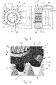
- schematically shows a front view of a starter motor with a drive pinion according to the prior art,
- Fig. 1b
- schematically shows a representation as in
Fig. 1a , however with a drive pinion according to the invention, - Fig. 2a
- schematically shows a lateral representation of the drive pinion and of a shaft according to
Fig. 1a according to the prior art, - Fig. 2b
- schematically shows a representation as in
Fig. 2a , however with the drive pinion according to the invention according toFig. 1b , - Fig. 3a
- schematically shows an oblique view from the direction A according to
Fig. 2a , - Fig. 3b
- schematically shows an oblique view from the direction A with the drive pinion and the shaft according to
Fig. 2b , - Fig. 4
- schematically shows a drive pinion according to the invention in a front view and a sectional representation along the section plane A-A,
- Fig. 5
- schematically shows an oblique view of an internal combustion engine according to the invention in a first engagement situation,
- Fig. 6a
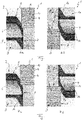
- schematically shows a side view of a drive pinion and of a shaft in a first engagement situation in the case of a correspondingly formed first gear ring on the drive pinion,
- Fig. 6b
- schematically shows a representation as in
Fig. 6a , but in the case of a correspondingly formed second gear ring on the shaft, - Fig. 7a
- schematically shows a representation as in
Fig. 6a , but in a second engagement situation, - Fig. 7b
- schematically shows a representation as in
Fig. 7a , but in a second engagement situation. - According to
Fig. 1b to 3b and5 to 7 , aninternal combustion engine 1 according to the invention comprises astarter motor 2 according to the invention with adrive pinion 3 likewise according to the invention, which during the starting of theinternal combustion engine 1 is drive connectable to ashaft 4 of theinternal combustion engine 1. According toFigures 1b to 3b as well as 5, 6a and 7a, thedrive pinion 3 according to the invention comprises afirst gear ring 5 withfirst teeth 6 located outside on the lateral surface and a first front side 7 (seeFig. 2b ) and is adjustable in theaxial direction 8, which according toFig. 1b runs perpendicularly to the figure plane, toward theshaft 4, wherein the firstfront side 7 of thedrive pinion 3 faces an associated, in particular second,front side 9 of theshaft 4. Similarly, the internal combustion engine 1' known from the prior art is formed according toFig. 1a, 2a and 3a , wherein the same reference characters here relate to the corresponding components merely distinguished by an apostrophe. In addition, theshaft 4 of theinternal combustion engine 1 has asecond gear ring 10 with second teeth 11 located outside on the lateral surface. In order to be able to rotate theshaft 4 via thedrive pinion 3 of thestarter motor 2 and thus start theinternal combustion engine 1, thedrive pinion 3 is thus pushed in theaxial direction 8 toward theshaft 4 until thefirst teeth 6 of thefirst gear ring 5 of thedrive pinion 3 mesh with the second teeth 11 of thesecond gear ring 10 of theshaft 4. However, when the first andsecond teeth 6, 11 are arranged aligned relative to one another in theaxial direction 8, these contact one another at contact points 12. Looking at the internal combustion engine 1' according toFig. 3a it is evident that when the drive pinion 3' is moved in the axial direction 8' toward the shaft 4' and simultaneously aligned teeth 6', 11', there is a total of three contact points 12', with this being accompanied not only by a high friction force but additionally also by a comparatively major wear. - Looking at
Fig. 1a, 2a and 3a further, which each show a drive pinion 3' according to the prior art, it is evident that these, on the first front side 7', have an associated elongated bevel 16' on each first tooth 6', wherein this bevel 16' with thedrive pinion 3 according to the invention is formed as rounded-outbevel 16 according toFig. 1b, 2b, 3b and4 . - An axial adjustment of the
drive pinion 3 in this case is effected for example using an electromagnetic actuator. - Looking at the
drive pinion 3 according to the invention according toFig. 1b, 2b and 3b as well as 4, 5, 6a and 7a it is evident, by contrast, that thefirst gear ring 5 is formed in such a manner that thefirst gear ring 5 and thesecond gear ring 10 are formed in such a manner that upon an axial adjusting of thedrive pinion 3 toward theshaft 4, a first engagement situation arises, in which exclusively afirst tooth 6 engages between two second teeth 11. The special gear ring form according to the invention may of course additionally or alternatively also be formed on thesecond gear ring 10, such that upon an axial adjusting of thedrive pinion 3 toward the shaft 4 a first engagement situation arises, in which exclusively a second tooth 11 engages between twofirst teeth 6. In this way, it is additionally achieved that when adjusting thedrive pinion 3 in theaxial direction 8 toward the shaft 4 a front-side contact takes place between thedrive pinion 3 and theshaft 4 exclusively at a maximum of twocontact points 12, which means that merely a maximum of twofirst teeth 6 of thedrive pinion 3 enter into contact with two associated second teeth 11 of theshaft 4 and the owing to thebevel 16 also only on a greatly reduced surface, as a result of which the wear and the friction can be substantially reduced. - According to an advantageous further development of the solution according to the invention, the
first gear ring 5 located outside on the lateral surface (seeFig. 2b, 3b ,4, 5 ,6a, 7a ) has a foot circle diameter df (seeFig. 4 ) and a useful tip circle diameter da, wherein the firstfront side 7 between the useful tip circle diameter da and a radial region B about the foot circle diameter df between df - 6mm < B < df + 3mm is rounded out with a radius R and because of this has a convex shape in this region, as is clearly evident in particular from the sectional representation A-A fromFig. 4 . Analogously or alternatively, thesecond gear ring 10 located outside on the lateral surface (seeFig. 6b, 7b ) may also have a foot circle diameter df (seeFig. 4 ) and a useful tip circle diameter da on, wherein the secondfront side 9 between the useful tip circle diameter da and a radial region B about the foot circle diameter df between df - 6 mm < B < df + 3 mm is rounded out with a radius R and because of this has a convex shape in this region, as is clearly evident, analogously to the sectional representation A-A, fromFig. 4 . Thebevel 16 is thus delimited radially to the outside by the useful tip circle diameter da and radially to the inside by the foot circle diameter df, wherein the foot circle diameter df may vary in a range df - 6 mm < B < df + 3 mm. It can be achieved in this way that upon an axial adjusting of thedrive pinion 3 toward the shaft 4 a first engagement situation arises, in which exclusively afirst tooth 6 engages between two second teeth 11 (seeFig. 6a ) or a second tooth 11 engages between two first teeth 6 (seeFig. 6b ). - Here, the first
front side 7 or the secondfront side 9 is rounded out with a radius R between the useful tip circle diameter da and the foot circle diameter df in a particularly preferred exemplary embodiment and in this case has a convex shape in this region. - An axial depth H between the first
front side 7 or the secondfront side 9 and the useful tip circle diameter da preferentially amounts to between 1 and 5mm. - Looking at
Fig. 1b, 3b ,4 and 5 further, it is evident that thedrive pinion 3 has ahub aperture 13 withinternal splines 14, via which it makes possible a rotationally fixed contact with ashaft 15 of thestarter motor 2, for example of an electric motor. Here, thedrive pinion 3 can be produced for example by way of cold extrusion. - Generally, a front-side friction during the starting of the
internal combustion engine 1 can be significantly reduced with thedrive pinion 3 according to the invention and thestarter motor 2 according to the invention, as a result of which a wear can be minimized at the same time. - According to the invention, also a
drive pinion 3 on which a radial region B starts in between df - 6mm and df +3 mm and ends at da. Blend depth (axial depth) h is in between 1 and 5 mm. Radius R is any value that is possible to connect the start and the end radius point. - When symmetry lines of a
first tooth 6 of the drive pinion 3 (first gear ring 5) and a second tooth 11 of thesecond gear ring 10 tooth are collinear only one tooth touch (one contact point 12) is possible. The main advantage of the gear pinions 3 shape is that it smoothly slides on a new or worn outring gear 10 head face (front side) 9. Because of this characteristic shape, it reduces the possibility of jamming. Jamming means to stuck/stop thedrive pinion 3 resp. thefirst gear ring 5 on the beginning of its travel into/through thesecond ring gear 10. Less force and torque is needed to engagegear rings ring gear innovative drive pinion 3. This inventive design allows engaging force and torque reduction which was not possible with previous designs. Previous designs start to get stuck (jamming) on a ring gear teeth if force and torque were reduced too much.
Claims (9)
- Internal combustion engine (1) having a starter motor (2) with a drive pinion (3), which when starting the internal combustion engine (1) is drive-connectable to a shaft (4) of the internal combustion engine (1),- wherein the drive pinion (3) comprises a first gear ring (5) with first teeth (6) located outside on the lateral surface and a first front side (7) and is adjustable in the axial direction (8) toward the shaft (4), wherein the first front side (7) faces the shaft (4),- wherein the shaft (4) of the internal combustion engine (1) comprises a second gear ring (10) with second teeth (11) located outside on the lateral surface and a second front side (9),- wherein the first gear ring (5) and the second gear ring (10) are designed in such a manner that upon an axial adjusting of the drive pinion (3) toward the shaft (4) a first engagement situation arises, in which exclusively a first tooth (6) engages between two second teeth (11) or a second tooth (11) engages between two first teeth (6),- the first gear ring (5) located outside on the lateral surface or the second gear ring (10) located outside on the lateral surface has a foot circle diameter df and a useful tip circle diameter da, the internal combustion engine (1) characterised- in that the first front side (7) or the second front side (9) between the useful tip circle diameter da and a radial region B about the foot circle diameter df between df - 6mm < B < df + 3mm is rounded out with a radius R and because of this has a convex bevel (16) in this region- in that an axial depth h between the first front side (7) or the second front side (9) and the useful tip circle diameter da amounts to between 1mm < h < 5mm.
- Internal combustion engine according to Claim 1, wherein the first front side (7) or the second front side (9) between the useful tip circle diameter da and the foot circle diameter df is rounded out with a radius R and because of this has a convex bevel (16) in this region.
- Internal combustion engine according to any one of the preceding claims, wherein- the drive pinion (3) comprises a hub aperture (13) with an internal toothing (14), and/or- the drive pinion (3) is produced by means of cold extrusion.
- Starter motor (2) for an internal combustion engine (1) according to Claim 1, having a drive pinion (3), which comprises a first gear ring (5) with first teeth (6) located outside on the lateral surface and a first front side (7),- wherein the first gear ring (5) located outside on the lateral surface has a foot circle diameter df and a useful tip circle diameter da, characterised in that- the first front side (7) between the useful tip circle diameter da and a radial region B about the foot circle diameter df between df - 6mm < B < df + 3mm is rounded out with a radius R and because of this has a convex bevel (16) in this region, and- an axial depth h between the first front side (7) and the useful tip circle diameter da amounts to between 1mm < h < 5mm.
- Starter motor according to Claim 4, wherein the first front side (7) between the useful tip circle diameter da and the foot circle diameter df is rounded out with a radius R and because of this has a convex bevel (16) in this region.
- Starter motor according to any one of the Claims 4 or 5, wherein- the drive pinion (3) comprises a hub aperture (13) with an internal toothing (14), and/or- the drive pinion (3) is produced by means of cold extrusion.
- Drive pinion (3) for a starter motor (2) according to Claim 4, which comprises a first gear ring (5) with first teeth (6) located outside on the lateral surface and a first front side (7),- wherein the first gear ring (5) located outside on the lateral surface has a foot circle diameter df and a useful tip circle diameter da, characterised in that- the first front side (7) between the useful tip circle diameter da and a radial region B about the foot circle diameter df between df - 6mm < B < df + 3mm is rounded out with a radius R and because of this has a convex bevel (16) in this region,- an axial depth h between the first front side (7) and the useful tip circle diameter da amounts to between 1mm < h < 5mm.
- Drive pinion according to Claim 7, wherein the first front side (7) between the useful tip circle diameter da and the foot circle diameter df is rounded out with a radius R and because of this has a convex bevel (16) in this region.
- Drive pinion according to any one of the Claims 7 or 8, wherein- the drive pinion (3) has a hub aperture (13) with internal splines (14), and/or- the drive pinion (3) is produced by means of cold extrusion.
Priority Applications (1)
| Application Number | Priority Date | Filing Date | Title |
|---|---|---|---|
| EP17210800.3A EP3505750B1 (en) | 2017-12-28 | 2017-12-28 | Internal combustion engine |
Applications Claiming Priority (1)
| Application Number | Priority Date | Filing Date | Title |
|---|---|---|---|
| EP17210800.3A EP3505750B1 (en) | 2017-12-28 | 2017-12-28 | Internal combustion engine |
Publications (2)
| Publication Number | Publication Date |
|---|---|
| EP3505750A1 EP3505750A1 (en) | 2019-07-03 |
| EP3505750B1 true EP3505750B1 (en) | 2021-10-20 |
Family
ID=60856915
Family Applications (1)
| Application Number | Title | Priority Date | Filing Date |
|---|---|---|---|
| EP17210800.3A Not-in-force EP3505750B1 (en) | 2017-12-28 | 2017-12-28 | Internal combustion engine |
Country Status (1)
| Country | Link |
|---|---|
| EP (1) | EP3505750B1 (en) |
Family Cites Families (3)
| Publication number | Priority date | Publication date | Assignee | Title |
|---|---|---|---|---|
| GB256089A (en) * | 1925-10-27 | 1926-08-05 | Herbert Horatio Trail | Improvements in starters for engines |
| US1979869A (en) * | 1932-10-31 | 1934-11-06 | Charter Drive Inc | Engine starter |
| JP2009168230A (en) * | 2008-01-21 | 2009-07-30 | Denso Corp | Pinion and starter using the same |
-
2017
- 2017-12-28 EP EP17210800.3A patent/EP3505750B1/en not_active Not-in-force
Also Published As
| Publication number | Publication date |
|---|---|
| EP3505750A1 (en) | 2019-07-03 |
Similar Documents
| Publication | Publication Date | Title |
|---|---|---|
| US8963391B2 (en) | Decoupler shaft for high speed generator | |
| CN100445126C (en) | Adjustment accessories for car seats | |
| US10851848B2 (en) | Sychronizer unit for a manual transmission, and manual transmission | |
| JP4330276B2 (en) | Two piece pinion gear | |
| EP3266653B1 (en) | Complete travel length clutching adjuster | |
| DE10103876B4 (en) | Valve timing adjustment device for internal combustion engines | |
| US9151191B1 (en) | Electrically actuated camshaft phaser | |
| EP3505750B1 (en) | Internal combustion engine | |
| EP2299071A1 (en) | Device for changing the phase of a camshaft relative to a crankshaft of a combustion engine | |
| EP3232075B1 (en) | Spline connection structure and spline shaft | |
| US10344807B2 (en) | Synchronizer device and synchronization method | |
| JP5716615B2 (en) | Water pump | |
| US8925404B2 (en) | Starting device for an internal combustion engine | |
| DE102014209312B4 (en) | Camshaft adjusting arrangement, comprising an axial securing means by means of a clamping sleeve | |
| DE102004060176B4 (en) | Variable valve timing | |
| CN111479641A (en) | Assembled camshaft and method for producing an assembled camshaft | |
| US2109155A (en) | Engine starter drive member | |
| CN111279055B (en) | Valve timing adjusting device | |
| US20130180484A1 (en) | Camshaft adjuster for an internal combustion engine | |
| EP4310315B1 (en) | Starter device and internal combustion engine having the same | |
| JP6535736B2 (en) | Cam shaft including an axially guided sliding element | |
| DE112020000896B4 (en) | Valve timing adjustment device | |
| CN109812516A (en) | Free-wheeling mechanism for starter and the starter for internal combustion engine | |
| EP3578803A1 (en) | Drive pinion for a starter of an internal combustion engine | |
| IT201800006989A1 (en) | Synchronizer for mechanical transmission, particularly for vehicle transmission. |
Legal Events
| Date | Code | Title | Description |
|---|---|---|---|
| PUAI | Public reference made under article 153(3) epc to a published international application that has entered the european phase |
Free format text: ORIGINAL CODE: 0009012 |
|
| STAA | Information on the status of an ep patent application or granted ep patent |
Free format text: STATUS: THE APPLICATION HAS BEEN PUBLISHED |
|
| AK | Designated contracting states |
Kind code of ref document: A1 Designated state(s): AL AT BE BG CH CY CZ DE DK EE ES FI FR GB GR HR HU IE IS IT LI LT LU LV MC MK MT NL NO PL PT RO RS SE SI SK SM TR |
|
| AX | Request for extension of the european patent |
Extension state: BA ME |
|
| STAA | Information on the status of an ep patent application or granted ep patent |
Free format text: STATUS: REQUEST FOR EXAMINATION WAS MADE |
|
| 17P | Request for examination filed |
Effective date: 20190918 |
|
| RBV | Designated contracting states (corrected) |
Designated state(s): AL AT BE BG CH CY CZ DE DK EE ES FI FR GB GR HR HU IE IS IT LI LT LU LV MC MK MT NL NO PL PT RO RS SE SI SK SM TR |
|
| GRAP | Despatch of communication of intention to grant a patent |
Free format text: ORIGINAL CODE: EPIDOSNIGR1 |
|
| STAA | Information on the status of an ep patent application or granted ep patent |
Free format text: STATUS: GRANT OF PATENT IS INTENDED |
|
| INTG | Intention to grant announced |
Effective date: 20210510 |
|
| GRAS | Grant fee paid |
Free format text: ORIGINAL CODE: EPIDOSNIGR3 |
|
| GRAA | (expected) grant |
Free format text: ORIGINAL CODE: 0009210 |
|
| STAA | Information on the status of an ep patent application or granted ep patent |
Free format text: STATUS: THE PATENT HAS BEEN GRANTED |
|
| AK | Designated contracting states |
Kind code of ref document: B1 Designated state(s): AL AT BE BG CH CY CZ DE DK EE ES FI FR GB GR HR HU IE IS IT LI LT LU LV MC MK MT NL NO PL PT RO RS SE SI SK SM TR |
|
| REG | Reference to a national code |
Ref country code: GB Ref legal event code: FG4D |
|
| REG | Reference to a national code |
Ref country code: CH Ref legal event code: EP |
|
| REG | Reference to a national code |
Ref country code: DE Ref legal event code: R096 Ref document number: 602017047833 Country of ref document: DE |
|
| REG | Reference to a national code |
Ref country code: IE Ref legal event code: FG4D |
|
| REG | Reference to a national code |
Ref country code: AT Ref legal event code: REF Ref document number: 1440148 Country of ref document: AT Kind code of ref document: T Effective date: 20211115 |
|
| REG | Reference to a national code |
Ref country code: LT Ref legal event code: MG9D |
|
| REG | Reference to a national code |
Ref country code: NL Ref legal event code: MP Effective date: 20211020 |
|
| REG | Reference to a national code |
Ref country code: AT Ref legal event code: MK05 Ref document number: 1440148 Country of ref document: AT Kind code of ref document: T Effective date: 20211020 |
|
| PG25 | Lapsed in a contracting state [announced via postgrant information from national office to epo] |
Ref country code: RS Free format text: LAPSE BECAUSE OF FAILURE TO SUBMIT A TRANSLATION OF THE DESCRIPTION OR TO PAY THE FEE WITHIN THE PRESCRIBED TIME-LIMIT Effective date: 20211020 Ref country code: LT Free format text: LAPSE BECAUSE OF FAILURE TO SUBMIT A TRANSLATION OF THE DESCRIPTION OR TO PAY THE FEE WITHIN THE PRESCRIBED TIME-LIMIT Effective date: 20211020 Ref country code: FI Free format text: LAPSE BECAUSE OF FAILURE TO SUBMIT A TRANSLATION OF THE DESCRIPTION OR TO PAY THE FEE WITHIN THE PRESCRIBED TIME-LIMIT Effective date: 20211020 Ref country code: BG Free format text: LAPSE BECAUSE OF FAILURE TO SUBMIT A TRANSLATION OF THE DESCRIPTION OR TO PAY THE FEE WITHIN THE PRESCRIBED TIME-LIMIT Effective date: 20220120 Ref country code: AT Free format text: LAPSE BECAUSE OF FAILURE TO SUBMIT A TRANSLATION OF THE DESCRIPTION OR TO PAY THE FEE WITHIN THE PRESCRIBED TIME-LIMIT Effective date: 20211020 |
|
| PG25 | Lapsed in a contracting state [announced via postgrant information from national office to epo] |
Ref country code: IS Free format text: LAPSE BECAUSE OF FAILURE TO SUBMIT A TRANSLATION OF THE DESCRIPTION OR TO PAY THE FEE WITHIN THE PRESCRIBED TIME-LIMIT Effective date: 20220220 Ref country code: SE Free format text: LAPSE BECAUSE OF FAILURE TO SUBMIT A TRANSLATION OF THE DESCRIPTION OR TO PAY THE FEE WITHIN THE PRESCRIBED TIME-LIMIT Effective date: 20211020 Ref country code: PT Free format text: LAPSE BECAUSE OF FAILURE TO SUBMIT A TRANSLATION OF THE DESCRIPTION OR TO PAY THE FEE WITHIN THE PRESCRIBED TIME-LIMIT Effective date: 20220221 Ref country code: PL Free format text: LAPSE BECAUSE OF FAILURE TO SUBMIT A TRANSLATION OF THE DESCRIPTION OR TO PAY THE FEE WITHIN THE PRESCRIBED TIME-LIMIT Effective date: 20211020 Ref country code: NO Free format text: LAPSE BECAUSE OF FAILURE TO SUBMIT A TRANSLATION OF THE DESCRIPTION OR TO PAY THE FEE WITHIN THE PRESCRIBED TIME-LIMIT Effective date: 20220120 Ref country code: NL Free format text: LAPSE BECAUSE OF FAILURE TO SUBMIT A TRANSLATION OF THE DESCRIPTION OR TO PAY THE FEE WITHIN THE PRESCRIBED TIME-LIMIT Effective date: 20211020 Ref country code: LV Free format text: LAPSE BECAUSE OF FAILURE TO SUBMIT A TRANSLATION OF THE DESCRIPTION OR TO PAY THE FEE WITHIN THE PRESCRIBED TIME-LIMIT Effective date: 20211020 Ref country code: HR Free format text: LAPSE BECAUSE OF FAILURE TO SUBMIT A TRANSLATION OF THE DESCRIPTION OR TO PAY THE FEE WITHIN THE PRESCRIBED TIME-LIMIT Effective date: 20211020 Ref country code: GR Free format text: LAPSE BECAUSE OF FAILURE TO SUBMIT A TRANSLATION OF THE DESCRIPTION OR TO PAY THE FEE WITHIN THE PRESCRIBED TIME-LIMIT Effective date: 20220121 Ref country code: ES Free format text: LAPSE BECAUSE OF FAILURE TO SUBMIT A TRANSLATION OF THE DESCRIPTION OR TO PAY THE FEE WITHIN THE PRESCRIBED TIME-LIMIT Effective date: 20211020 |
|
| REG | Reference to a national code |
Ref country code: DE Ref legal event code: R097 Ref document number: 602017047833 Country of ref document: DE |
|
| PG25 | Lapsed in a contracting state [announced via postgrant information from national office to epo] |
Ref country code: SM Free format text: LAPSE BECAUSE OF FAILURE TO SUBMIT A TRANSLATION OF THE DESCRIPTION OR TO PAY THE FEE WITHIN THE PRESCRIBED TIME-LIMIT Effective date: 20211020 Ref country code: SK Free format text: LAPSE BECAUSE OF FAILURE TO SUBMIT A TRANSLATION OF THE DESCRIPTION OR TO PAY THE FEE WITHIN THE PRESCRIBED TIME-LIMIT Effective date: 20211020 Ref country code: RO Free format text: LAPSE BECAUSE OF FAILURE TO SUBMIT A TRANSLATION OF THE DESCRIPTION OR TO PAY THE FEE WITHIN THE PRESCRIBED TIME-LIMIT Effective date: 20211020 Ref country code: MC Free format text: LAPSE BECAUSE OF FAILURE TO SUBMIT A TRANSLATION OF THE DESCRIPTION OR TO PAY THE FEE WITHIN THE PRESCRIBED TIME-LIMIT Effective date: 20211020 Ref country code: EE Free format text: LAPSE BECAUSE OF FAILURE TO SUBMIT A TRANSLATION OF THE DESCRIPTION OR TO PAY THE FEE WITHIN THE PRESCRIBED TIME-LIMIT Effective date: 20211020 Ref country code: DK Free format text: LAPSE BECAUSE OF FAILURE TO SUBMIT A TRANSLATION OF THE DESCRIPTION OR TO PAY THE FEE WITHIN THE PRESCRIBED TIME-LIMIT Effective date: 20211020 Ref country code: CZ Free format text: LAPSE BECAUSE OF FAILURE TO SUBMIT A TRANSLATION OF THE DESCRIPTION OR TO PAY THE FEE WITHIN THE PRESCRIBED TIME-LIMIT Effective date: 20211020 |
|
| REG | Reference to a national code |
Ref country code: CH Ref legal event code: PL |
|
| PLBE | No opposition filed within time limit |
Free format text: ORIGINAL CODE: 0009261 |
|
| STAA | Information on the status of an ep patent application or granted ep patent |
Free format text: STATUS: NO OPPOSITION FILED WITHIN TIME LIMIT |
|
| REG | Reference to a national code |
Ref country code: BE Ref legal event code: MM Effective date: 20211231 |
|
| 26N | No opposition filed |
Effective date: 20220721 |
|
| GBPC | Gb: european patent ceased through non-payment of renewal fee |
Effective date: 20220120 |
|
| PG25 | Lapsed in a contracting state [announced via postgrant information from national office to epo] |
Ref country code: LU Free format text: LAPSE BECAUSE OF NON-PAYMENT OF DUE FEES Effective date: 20211228 Ref country code: IE Free format text: LAPSE BECAUSE OF NON-PAYMENT OF DUE FEES Effective date: 20211228 Ref country code: GB Free format text: LAPSE BECAUSE OF NON-PAYMENT OF DUE FEES Effective date: 20220120 Ref country code: AL Free format text: LAPSE BECAUSE OF FAILURE TO SUBMIT A TRANSLATION OF THE DESCRIPTION OR TO PAY THE FEE WITHIN THE PRESCRIBED TIME-LIMIT Effective date: 20211020 |
|
| PG25 | Lapsed in a contracting state [announced via postgrant information from national office to epo] |
Ref country code: SI Free format text: LAPSE BECAUSE OF FAILURE TO SUBMIT A TRANSLATION OF THE DESCRIPTION OR TO PAY THE FEE WITHIN THE PRESCRIBED TIME-LIMIT Effective date: 20211020 Ref country code: FR Free format text: LAPSE BECAUSE OF NON-PAYMENT OF DUE FEES Effective date: 20211231 Ref country code: BE Free format text: LAPSE BECAUSE OF NON-PAYMENT OF DUE FEES Effective date: 20211231 |
|
| PG25 | Lapsed in a contracting state [announced via postgrant information from national office to epo] |
Ref country code: LI Free format text: LAPSE BECAUSE OF NON-PAYMENT OF DUE FEES Effective date: 20211231 Ref country code: CH Free format text: LAPSE BECAUSE OF NON-PAYMENT OF DUE FEES Effective date: 20211231 |
|
| PG25 | Lapsed in a contracting state [announced via postgrant information from national office to epo] |
Ref country code: IT Free format text: LAPSE BECAUSE OF FAILURE TO SUBMIT A TRANSLATION OF THE DESCRIPTION OR TO PAY THE FEE WITHIN THE PRESCRIBED TIME-LIMIT Effective date: 20211020 |
|
| PGFP | Annual fee paid to national office [announced via postgrant information from national office to epo] |
Ref country code: DE Payment date: 20221227 Year of fee payment: 6 |
|
| PG25 | Lapsed in a contracting state [announced via postgrant information from national office to epo] |
Ref country code: CY Free format text: LAPSE BECAUSE OF FAILURE TO SUBMIT A TRANSLATION OF THE DESCRIPTION OR TO PAY THE FEE WITHIN THE PRESCRIBED TIME-LIMIT Effective date: 20211020 |
|
| PG25 | Lapsed in a contracting state [announced via postgrant information from national office to epo] |
Ref country code: HU Free format text: LAPSE BECAUSE OF FAILURE TO SUBMIT A TRANSLATION OF THE DESCRIPTION OR TO PAY THE FEE WITHIN THE PRESCRIBED TIME-LIMIT; INVALID AB INITIO Effective date: 20171228 |
|
| PG25 | Lapsed in a contracting state [announced via postgrant information from national office to epo] |
Ref country code: MK Free format text: LAPSE BECAUSE OF FAILURE TO SUBMIT A TRANSLATION OF THE DESCRIPTION OR TO PAY THE FEE WITHIN THE PRESCRIBED TIME-LIMIT Effective date: 20211020 |
|
| REG | Reference to a national code |
Ref country code: DE Ref legal event code: R119 Ref document number: 602017047833 Country of ref document: DE |
|
| PG25 | Lapsed in a contracting state [announced via postgrant information from national office to epo] |
Ref country code: MT Free format text: LAPSE BECAUSE OF FAILURE TO SUBMIT A TRANSLATION OF THE DESCRIPTION OR TO PAY THE FEE WITHIN THE PRESCRIBED TIME-LIMIT Effective date: 20211020 |
|
| PG25 | Lapsed in a contracting state [announced via postgrant information from national office to epo] |
Ref country code: DE Free format text: LAPSE BECAUSE OF NON-PAYMENT OF DUE FEES Effective date: 20240702 |
|
| PG25 | Lapsed in a contracting state [announced via postgrant information from national office to epo] |
Ref country code: DE Free format text: LAPSE BECAUSE OF NON-PAYMENT OF DUE FEES Effective date: 20240702 |
|
| PG25 | Lapsed in a contracting state [announced via postgrant information from national office to epo] |
Ref country code: TR Free format text: LAPSE BECAUSE OF FAILURE TO SUBMIT A TRANSLATION OF THE DESCRIPTION OR TO PAY THE FEE WITHIN THE PRESCRIBED TIME-LIMIT Effective date: 20211020 |