EP3505612A1 - Liquid cell culture medium recovering filter unit, liquid cell culture medium recovering method, and liquid cell culture medium recovering kit - Google Patents
Liquid cell culture medium recovering filter unit, liquid cell culture medium recovering method, and liquid cell culture medium recovering kit Download PDFInfo
- Publication number
- EP3505612A1 EP3505612A1 EP17871939.9A EP17871939A EP3505612A1 EP 3505612 A1 EP3505612 A1 EP 3505612A1 EP 17871939 A EP17871939 A EP 17871939A EP 3505612 A1 EP3505612 A1 EP 3505612A1
- Authority
- EP
- European Patent Office
- Prior art keywords
- culture medium
- cell culture
- liquid cell
- porous metal
- metal membrane
- Prior art date
- Legal status (The legal status is an assumption and is not a legal conclusion. Google has not performed a legal analysis and makes no representation as to the accuracy of the status listed.)
- Pending
Links
Images





Classifications
-
- C—CHEMISTRY; METALLURGY
- C12—BIOCHEMISTRY; BEER; SPIRITS; WINE; VINEGAR; MICROBIOLOGY; ENZYMOLOGY; MUTATION OR GENETIC ENGINEERING
- C12M—APPARATUS FOR ENZYMOLOGY OR MICROBIOLOGY; APPARATUS FOR CULTURING MICROORGANISMS FOR PRODUCING BIOMASS, FOR GROWING CELLS OR FOR OBTAINING FERMENTATION OR METABOLIC PRODUCTS, i.e. BIOREACTORS OR FERMENTERS
- C12M47/00—Means for after-treatment of the produced biomass or of the fermentation or metabolic products, e.g. storage of biomass
- C12M47/02—Separating microorganisms from the culture medium; Concentration of biomass
-
- C—CHEMISTRY; METALLURGY
- C12—BIOCHEMISTRY; BEER; SPIRITS; WINE; VINEGAR; MICROBIOLOGY; ENZYMOLOGY; MUTATION OR GENETIC ENGINEERING
- C12M—APPARATUS FOR ENZYMOLOGY OR MICROBIOLOGY; APPARATUS FOR CULTURING MICROORGANISMS FOR PRODUCING BIOMASS, FOR GROWING CELLS OR FOR OBTAINING FERMENTATION OR METABOLIC PRODUCTS, i.e. BIOREACTORS OR FERMENTERS
- C12M1/00—Apparatus for enzymology or microbiology
- C12M1/12—Apparatus for enzymology or microbiology with sterilisation, filtration or dialysis means
-
- C—CHEMISTRY; METALLURGY
- C12—BIOCHEMISTRY; BEER; SPIRITS; WINE; VINEGAR; MICROBIOLOGY; ENZYMOLOGY; MUTATION OR GENETIC ENGINEERING
- C12M—APPARATUS FOR ENZYMOLOGY OR MICROBIOLOGY; APPARATUS FOR CULTURING MICROORGANISMS FOR PRODUCING BIOMASS, FOR GROWING CELLS OR FOR OBTAINING FERMENTATION OR METABOLIC PRODUCTS, i.e. BIOREACTORS OR FERMENTERS
- C12M25/00—Means for supporting, enclosing or fixing the microorganisms, e.g. immunocoatings
- C12M25/02—Membranes; Filters
-
- C—CHEMISTRY; METALLURGY
- C12—BIOCHEMISTRY; BEER; SPIRITS; WINE; VINEGAR; MICROBIOLOGY; ENZYMOLOGY; MUTATION OR GENETIC ENGINEERING
- C12M—APPARATUS FOR ENZYMOLOGY OR MICROBIOLOGY; APPARATUS FOR CULTURING MICROORGANISMS FOR PRODUCING BIOMASS, FOR GROWING CELLS OR FOR OBTAINING FERMENTATION OR METABOLIC PRODUCTS, i.e. BIOREACTORS OR FERMENTERS
- C12M25/00—Means for supporting, enclosing or fixing the microorganisms, e.g. immunocoatings
- C12M25/10—Hollow fibers or tubes
-
- C—CHEMISTRY; METALLURGY
- C12—BIOCHEMISTRY; BEER; SPIRITS; WINE; VINEGAR; MICROBIOLOGY; ENZYMOLOGY; MUTATION OR GENETIC ENGINEERING
- C12M—APPARATUS FOR ENZYMOLOGY OR MICROBIOLOGY; APPARATUS FOR CULTURING MICROORGANISMS FOR PRODUCING BIOMASS, FOR GROWING CELLS OR FOR OBTAINING FERMENTATION OR METABOLIC PRODUCTS, i.e. BIOREACTORS OR FERMENTERS
- C12M29/00—Means for introduction, extraction or recirculation of materials, e.g. pumps
- C12M29/04—Filters; Permeable or porous membranes or plates, e.g. dialysis
-
- C—CHEMISTRY; METALLURGY
- C12—BIOCHEMISTRY; BEER; SPIRITS; WINE; VINEGAR; MICROBIOLOGY; ENZYMOLOGY; MUTATION OR GENETIC ENGINEERING
- C12M—APPARATUS FOR ENZYMOLOGY OR MICROBIOLOGY; APPARATUS FOR CULTURING MICROORGANISMS FOR PRODUCING BIOMASS, FOR GROWING CELLS OR FOR OBTAINING FERMENTATION OR METABOLIC PRODUCTS, i.e. BIOREACTORS OR FERMENTERS
- C12M29/00—Means for introduction, extraction or recirculation of materials, e.g. pumps
- C12M29/16—Hollow fibers
-
- C—CHEMISTRY; METALLURGY
- C12—BIOCHEMISTRY; BEER; SPIRITS; WINE; VINEGAR; MICROBIOLOGY; ENZYMOLOGY; MUTATION OR GENETIC ENGINEERING
- C12M—APPARATUS FOR ENZYMOLOGY OR MICROBIOLOGY; APPARATUS FOR CULTURING MICROORGANISMS FOR PRODUCING BIOMASS, FOR GROWING CELLS OR FOR OBTAINING FERMENTATION OR METABOLIC PRODUCTS, i.e. BIOREACTORS OR FERMENTERS
- C12M3/00—Tissue, human, animal or plant cell, or virus culture apparatus
- C12M3/06—Tissue, human, animal or plant cell, or virus culture apparatus with filtration, ultrafiltration, inverse osmosis or dialysis means
-
- C—CHEMISTRY; METALLURGY
- C12—BIOCHEMISTRY; BEER; SPIRITS; WINE; VINEGAR; MICROBIOLOGY; ENZYMOLOGY; MUTATION OR GENETIC ENGINEERING
- C12N—MICROORGANISMS OR ENZYMES; COMPOSITIONS THEREOF; PROPAGATING, PRESERVING, OR MAINTAINING MICROORGANISMS; MUTATION OR GENETIC ENGINEERING; CULTURE MEDIA
- C12N1/00—Microorganisms; Compositions thereof; Processes of propagating, maintaining or preserving microorganisms or compositions thereof; Processes of preparing or isolating a composition containing a microorganism; Culture media therefor
- C12N1/02—Separating microorganisms from their culture media
-
- C—CHEMISTRY; METALLURGY
- C12—BIOCHEMISTRY; BEER; SPIRITS; WINE; VINEGAR; MICROBIOLOGY; ENZYMOLOGY; MUTATION OR GENETIC ENGINEERING
- C12N—MICROORGANISMS OR ENZYMES; COMPOSITIONS THEREOF; PROPAGATING, PRESERVING, OR MAINTAINING MICROORGANISMS; MUTATION OR GENETIC ENGINEERING; CULTURE MEDIA
- C12N5/00—Undifferentiated human, animal or plant cells, e.g. cell lines; Tissues; Cultivation or maintenance thereof; Culture media therefor
Definitions
- the present invention relates to a liquid cell culture medium collecting filter unit, a liquid cell culture medium collecting method, and a liquid cell culture medium collecting kit.
- Cell (cultured cell) growth requires a culture medium serving as a nutrient source.
- the culture medium needs to be replaced at regular intervals.
- a known method for replacing a culture medium uses, for example, centrifugation (see Patent Document 1).
- the method for replacing a culture medium using centrifugation is carried out, for example, in the following manner.
- a cell-containing liquid cell culture medium in a container targeted for culture medium replacement is dispensed into centrifugation tubes.
- each centrifugation tube is centrifuged, so that cells are concentrated at the bottom of each centrifugation tube.
- the supernatant, which is part of the liquid cell culture medium, in each centrifugation tube is collected.
- the cell-containing liquid cell culture medium that remains in each centrifugation tube is returned to the container.
- a fresh liquid cell culture medium is placed in the container. Accordingly, replacement of the culture medium in the container is completed.
- Patent Document 1 Japanese Unexamined Patent Application Publication No. 2004-105139
- the step of collecting the supernatant which is part of the liquid cell culture medium is performed by workers (persons). Therefore, some workers may collect not only the supernatant but also cells and reduce the proportion of cells remaining in the container. In other words, there are large variations in the proportion of remaining cells depending on worker. In addition, it takes a long time to collect the liquid cell culture medium.
- an object of the present invention is to provide a liquid cell culture medium collecting filter unit, a liquid cell culture medium collecting method, and a liquid cell culture medium collecting kit, which can reduce variations in the proportion of remaining cells and can shorten the time required to collect a liquid cell culture medium.
- a liquid cell culture medium collecting filter unit includes a porous metal membrane that filters out cells in a liquid cell culture medium; a holding member that holds a peripheral portion of the porous metal membrane; and a tubular member that has a hollow part serving as a flow path for the liquid cell culture medium and is connected to the holding member such that the hollow part faces at least part of a main surface of the porous metal membrane.
- a liquid cell culture medium collecting method includes a filter unit-placing step of placing, in a container that contains a cell-containing liquid cell culture medium, a liquid cell culture medium collecting filter unit including a porous metal membrane that filters out cells in the liquid cell culture medium, a holding member that holds a peripheral portion of the porous metal membrane, and a tubular member that has a hollow part serving as a flow path for the liquid cell culture medium and is connected to the holding member such that the hollow part faces at least part of a main surface of the porous metal membrane; and a collecting step of introducing the liquid cell culture medium in the container to the flow path through the porous metal membrane and collecting the liquid cell culture medium outside the container.
- the liquid cell culture medium collecting filter unit and the liquid cell culture medium collecting method according to the aspects of the present invention can reduce variations in the proportion of remaining cells and can shorten the time required to collect a liquid cell culture medium.
- a liquid cell culture medium collecting filter unit includes a porous metal membrane that filters out cells in a liquid cell culture medium; a holding member that holds a peripheral portion of the porous metal membrane; and a tubular member that has a hollow part serving a flow path for the liquid cell culture medium and is connected to the holding member such that the hollow part faces at least part of a main surface of the porous metal membrane.
- this structure includes the porous metal membrane that filters out cells in the liquid cell culture medium, the cells can remain in the container as a result of filtering out the cells by using the porous metal membrane, and only the liquid cell culture medium can be collected through liquid culture medium flow paths. This can reduce variations in the proportion of remaining cells and achieve a high proportion of remaining cells. Since cells are less likely to be attached to a porous metal membrane than to, for example, a porous resin membrane, it is possible to prevent inhibition of collection of the liquid cell culture medium caused by clogging of membrane pores with cells. Thus, the time required to collect the liquid cell culture medium can be shortened.
- the holding member preferably includes a first frame member and a second frame member between which the peripheral portion of the porous metal membrane is sandwiched.
- the peripheral portion of the porous metal membrane preferably has a first bent portion and a second bent portion.
- the peripheral portion of the porous metal membrane is preferably sandwiched between the first frame member and the second frame member so as to have a stripe-shaped protrusion between the first bent portion and the second bent portion.
- the stripe-shaped protrusion between the first bent portion and the second bent portion in the porous metal membrane can increase the friction between the peripheral portion of the porous metal membrane and the first frame member and the second frame member.
- This structure can avoid the porous metal membrane from falling out of the frame members even if the liquid cell culture medium is collected at a high flow rate. The liquid cell culture medium can thus be collected in a short time.
- a plurality of the stripe-shaped protrusions is preferably provided between the first bent portion and the second bent portion, and the stripe-shaped protrusions are preferably oriented in random directions.
- This structure can increase the friction between the peripheral portion of the porous metal membrane and the first frame member and the second frame member and can further improve the holding power of the first frame member and the second frame member used to hold the porous metal membrane.
- An annular protrusion that protrudes in the thickness direction of the holding member is preferably provided on a main surface of the holding member away from the tubular member.
- the porous metal membrane is preferably disposed on the inner side of the protrusion. According to this structure, the porous metal membrane can be positioned closer to the bottom of the container, and the liquid surface can be lowered to the main surface below the porous metal membrane. The amount of the collected liquid cell culture medium can thus be increased without reducing the proportion of remaining cells. Since the porous metal membrane positioned closer to the bottom of the container contacts a large amount of the liquid cell culture medium, the cells attached to the porous metal membrane are washed away, which can make it difficult to cause clogging.
- the porous metal membrane is preferably flush or substantially flush with an opening plane defined by the end portion of the protrusion of the holding member. This structure enables the porous metal membrane to be positioned still closer to the bottom of the container and can increase the amount of the collected liquid cell culture medium without reducing the proportion of remaining cells. This structure can also prevent the porous metal membrane from being clogged with cells to shorten the working time and can reduce the stress on the cells.
- a liquid cell culture medium collecting method includes a filter unit-placing step of placing, in a container that contains a cell-containing liquid cell culture medium, a liquid cell culture medium collecting filter unit including a porous metal membrane that filters out cells in the liquid cell culture medium, a holding member that holds the peripheral portion of the porous metal membrane, and a tubular member that has a hollow part serving as a flow path for the liquid cell culture medium and is connected to the holding member such that the hollow part faces at least part of a main surface of the porous metal membrane; and a collecting step of introducing the liquid cell culture medium in the container to the flow path through the porous metal membrane and collecting the liquid cell culture medium outside the container.
- the cells can remain in the container as a result of filtering out the cells by using the porous metal membrane, and only the liquid cell culture medium can be collected through the liquid culture medium flow paths.
- This configuration can reduce variations in the proportion of remaining cells. Since cells are less likely to be attached to a porous metal membrane than to, for example, a porous resin membrane, it is possible to prevent inhibition of collection of a liquid cell culture medium caused by clogging of membrane pores with cells. Thus, the time required to collect the liquid cell culture medium can be shortened.
- the method may further include, after the collecting step, a supplying step of supplying a fresh liquid cell culture medium to the container.
- a supplying step of supplying a fresh liquid cell culture medium to the container can be replaced by a fresh liquid cell culture medium.
- the fresh liquid cell culture medium may flow through the flow path and may be supplied to the container through the porous metal membrane. According to this method, even if cells are attached to the porous metal membrane, the cells can be detached from the porous metal membrane (that is, the porous metal membrane can be backwashed) under the pressure of the fresh liquid cell culture medium. As a result, the time required to replace the liquid cell culture medium can be shortened.
- the method may further include, after the supplying step, a re-collecting step of introducing the liquid cell culture medium in the container to the flow path through the porous metal membrane and collecting the liquid cell culture medium outside the container.
- a re-collecting step of introducing the liquid cell culture medium in the container to the flow path through the porous metal membrane and collecting the liquid cell culture medium outside the container.
- the liquid cell culture medium can be continuously collected by using the same porous metal membrane.
- a liquid cell culture medium collecting kit is a liquid cell culture medium collecting kit used in the liquid cell culture medium collecting method and includes the liquid cell culture medium collecting filter unit. This structure can reduce variations in the proportion of remaining cells and can shorten the time required to collect the liquid cell culture medium.
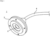
- Fig. 1 is a perspective view illustrating the schematic structure of a liquid cell culture medium collecting filter unit according to an embodiment of the present invention.
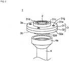
- Fig. 2 is an exploded perspective view of the liquid cell culture medium collecting filter unit in Fig. 1 .
- Fig. 3 is an exploded sectional view of the liquid cell culture medium collecting filter unit in Fig. 1 .
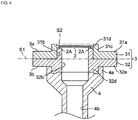
- Fig. 4 is an assembly sectional view of the liquid cell culture medium collecting filter unit in Fig. 1 .
- Fig. 5 is a partially enlarged sectional view of Fig. 4 .
- a liquid cell culture medium collecting filter unit 1 includes a porous metal membrane 2, a holding member 3, which holds the peripheral portion of the porous metal membrane 2, and a tubular member 4, which is connected to the holding member 3.
- the holding member 3 holds a peripheral portion 2A of the porous metal membrane 2 as illustrated in Fig. 3 to Fig. 5 .
- the holding member 3 includes a first frame member 31 and a second frame member 32.
- the peripheral portion 2A of the porous metal membrane 2 can be sandwiched between the first frame member 31 and the second frame member 32.
- the first frame member 31 includes an annular flat portion 31a and an annular protrusion 31c, which is positioned at the section around a central through-hole 31b so as to protrude away from the tubular member 4.
- the flat portion 31a has a diameter of, for example, 18 mm.
- the flat portion 31a has a thickness of, for example, 1.5 mm.
- the protrusion 31c has a height of, for example, 1.5 mm.
- An annular flange 31d which protrudes toward the center of the through-hole 31b, is formed on the inner surface of the annular protrusion 31c.
- the flange 31d is provided at a distance of, for example, 0.1 mm from the top of the protrusion 31c toward the flat portion 31a.
- An end portion 31f of the flange 31d close to the center of the through-hole 31b has a small thickness so as to form a slope surface 31e on the tubular member 4 side.
- the thickness of the flange 31d adjacent to the protrusion 31c is, for example, 0.3 mm.
- the thickness of the end portion 31f of the flange 31d is, for example, 0.2 mm.
- the angle of the slope surface 31e is, for example, 45 degrees.
- the second frame member 32 includes an annular flat portion 32a; an annular protrusion 32c, which is positioned at the section around a central through-hole 32b so as to protrude away from the tubular member 4; and an annular protrusion 32d, which is positioned at the section around the central through-hole 32b so as to protrude toward the tubular member 4.
- the flat portion 32a has a diameter of, for example, 18 mm.
- the flat portion 32a has a thickness of, for example, 1.5 mm.
- the protrusion 32d has a height of, for example, 1.5 mm.
- the protrusion 32c has an outer diameter that is slightly smaller than the diameter of the through-hole 31b such that the protrusion 32c can be inserted into the through-hole 31b of the first frame member 31.
- An end portion 32f of the protrusion 32c is shaped in conformance with the shape of the flange 31d on the tubular member 4 side. In other words, the end portion 32f has a slope surface 32e corresponding to the slope surface 31e.
- the porous metal membrane 2 is held so as to have tension in the plane direction when the peripheral portion 2A is sandwiched between the flange 31d of the first frame member 31 and the end portion 32f of the protrusion 32c of the second frame member 32 and lies along the slope surface 31e and the slope surface 32e.
- the peripheral portion 2A of the porous metal membrane 2 is sandwiched at the position distant from a central plane S1, which is a central plane in the thickness direction of the holding member 3, in the thickness direction.
- the porous metal membrane 2 is disposed on the inner side of the annular protrusion 31c.
- the porous metal membrane 2 is substantially flush with an opening plane S2 defined by the end portion of the annular protrusion 31c.
- the flat portion 31a of the first frame member 31 has a plurality of through-pores 31g, which penetrates the first frame member 31 in the thickness direction.
- the through-pores 31g are arranged at regular intervals in the circumferential direction of the flat portion 31a.
- the flat portion 32a of the second frame member 32 has a plurality of through-pores 32g, which penetrates the second frame member 32 in the thickness direction.
- the through-pores 32g are arranged at regular intervals in the circumferential direction of the flat portion 32a so as to correspond to the through-pores 31g.
- the first frame member 31 and the second frame member 32 are fixed to each other by inserting fastening members (not illustrated), such as screws, into the respective through-pores 31g and 32g while the protrusion 32c of the second frame member 32 is inserted in the through-hole 31b of the first frame member 31.
- the tubular member 4 includes a fitting portion 4a, which can be fitted to the protrusion 32d of the second frame member 32.
- the tubular member 4 is detachably attached to the second frame member 32 by fitting the fitting portion 4a onto the outer surface of the protrusion 32d of the second frame member 32.
- the tubular member 4 has a hollow part 4b serving as a flow path for the liquid cell culture medium.
- the tubular member 4 is connected to the second frame member 32 such that the hollow part 4b faces at least part of the main surface of the porous metal membrane 2. With this configuration, the liquid cell culture medium that has passed through the porous metal membrane 2 can be collected through the hollow part 4b serving as a flow path for the liquid cell culture medium.
- Examples of the materials of the first frame member 31, the second frame member 32, and the tubular member 4 include metals, such as duralumin, aluminum, and stainless steel (SUS); and resins, such as polyethylene, polystyrene, polypropylene, polycarbonate, polyacetal, and polyetherimide.
- metals such as duralumin, aluminum, and stainless steel (SUS)
- resins such as polyethylene, polystyrene, polypropylene, polycarbonate, polyacetal, and polyetherimide.
- Fig. 6 is a partially enlarged perspective view illustrating the schematic structure of the porous metal membrane 2.
- the porous metal membrane 2 is used to filter out cells contained in the liquid cell culture medium.
- the porous metal membrane 2 is used to filter out cells contained in the liquid cell culture medium.
- the cells are, for example, spheroids.
- the porous metal membrane 2 has a pair of main surfaces 21a and 21b, which oppose each other.
- the porous metal membrane 2 has a plurality of through-pores 21c, which penetrates both the main surfaces 21a and 21b.
- the through-pores 21c separate cells from the liquid cell culture medium.
- the shape and size of the through-pores 21c are appropriately set according to the shape and size of the cells.
- the through-pores 21c are arranged, for example, at regular intervals or periodically.
- the shape of the through-pores 21c is, for example, square as viewed from the main surface 21a side of the porous metal membrane 2.
- the through-pores 21c are arranged in a square lattice.
- each through-pore 21c is, for example, 0.1 ⁇ m or more and 600 ⁇ m or less in length and 0.1 ⁇ m or more and 600 ⁇ m or less in width.
- the interval between the through-pores 21c is, for example, larger than the size of the through-pores 21c by a factor of preferably 1 time or more and 10 times or less, and more preferably 3 times or less.
- the opening ratio of the through-pores 21c in the porous metal membrane 2 is, for example, 10% or more.
- the shape of the through-pores 21c may be, for example, regular hexagon as viewed from the main surface 21a side of the porous metal membrane 2.
- the through-pores 21c may be arranged to form a honeycomb structure.
- Examples of the material of the porous metal membrane 2 include gold, silver, copper, platinum, nickel, stainless steel, palladium, titanium, cobalt, alloys thereof, and oxides thereof.
- the size of the porous metal membrane 2 is, for example, 6 mm in diameter.
- the thickness of the porous metal membrane 2 is, for example, 0.1 ⁇ m or more and 100 ⁇ m or less and preferably 0.1 ⁇ m or more and 50 ⁇ m or less.
- the porous metal membrane 2 has, for example, a circular, elliptical, or polygonal contour. In this embodiment, the porous metal membrane 2 has a circular contour.
- the peripheral portion of the porous metal membrane 2 may have the through-pores 21c or may not have the through-pores 21c.
- the peripheral portion 2A of the porous metal membrane 2 is sandwiched between the slope surface 31e of the first frame member 31 and the slope surface 32e of the second frame member 32 so as to have a first bent portion 2a and a second bent portion 2b.
- the peripheral portion 2A of the porous metal membrane 2 is sandwiched so as to have stripe-shaped protrusions 2c between the first bent portion 2a and the second bent portion 2b.
- the stripe-shaped protrusions 2c refer to parts that protrude from one of the main surfaces of the porous metal membrane 2 and have a height that is 0.1 times or more and 2 times or less the thickness of the porous metal membrane 2.
- the stripe-shaped protrusions 2c can increase the friction between the peripheral portion 2A of the porous metal membrane 2 and the first frame member 31 and the second frame member 32.
- a plurality of the stripe-shaped protrusions 2c is provided between the first bent portion 2a and the second bent portion 2b, and the stripe-shaped protrusions 2c are oriented in random directions.
- This structure can increase the friction between the peripheral portion 2A of the porous metal membrane 2 and the first frame member 31 and the second frame member 32 and can further improve the holding power of the first frame member 31 and the second frame member 32 used to hold the porous metal membrane 2.
- the stripe-shaped protrusions 2c may be formed of, for example, the wrinkles of the porous metal membrane 2.
- wrinkles refers to fine stripes created as a result of loosening or shrinking of the porous metal membrane 2.
- the porous metal membrane 2 itself can form the stripe-shaped protrusions 2c, and there is no need to separately dispose members serving as the stripe-shaped protrusions 2c.
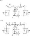
- FIG. 9 is a schematic diagram illustrating an example of the liquid cell culture medium collecting and replacing method.
- the liquid cell culture medium collecting filter unit 1 is placed in a container 5 that contains a liquid cell culture medium CCS containing cells CE (filter unit-placing step). More specifically, one end portion of the tubular member 4 is placed in the container 5 such that the porous metal membrane 2 is positioned in the liquid cell culture medium CCS.
- the other end portion of the tubular member 4 is connected to a pump P1 at this time.
- the pump P1 is connected to a collection pipe 61 through which the liquid cell culture medium CCS collected from the container 5 flows into a liquid culture medium collection container 62.
- a supply pipe 71 is placed in the container 5.
- the other end portion of the supply pipe 71 is connected to a pump P2.
- the pump P2 is connected to a suction pipe 73 through which the fresh liquid cell culture medium CCS is sucked from a liquid culture medium storage container 72.
- the container 5 has a bottle shape and has a cap 51, which closes the opening.
- the tubular member 4 and the supply pipe 71 penetrate the cap 51.
- the pump P1 is driven to suck the liquid cell culture medium CCS in the container 5 through the porous metal membrane 2, and the liquid cell culture medium CCS is collected in the liquid culture medium collection container 62, which is located outside the container 5, through the tubular member 4 (collecting step). Since the porous metal membrane 2 filters out the cells CE in the container 5 at this time, the cells CE remain in the container 5, and only the liquid cell culture medium CCS is collected in the liquid culture medium collection container 62 through the tubular member 4 and the collection pipe 61.
- the pump P2 is driven to supply the fresh liquid cell culture medium CCS in the liquid culture medium storage container 72 to the container 5 through the suction pipe 73 and the supply pipe 71 (supplying step). Accordingly, a fresh culture medium can be prepared by replacing the liquid cell culture medium CCS in the container 5.
- the pump P1 is driven to suck the liquid cell culture medium CCS in the container 5 through the porous metal membrane 2, and the liquid cell culture medium CCS is collected in the liquid culture medium collection container 62, which is located outside the container 5, through the tubular member 4 (re-collecting step).
- the pump P2 is driven to supply the fresh liquid cell culture medium CCS in the liquid culture medium storage container 72 to the container 5 through the suction pipe 73 and the supply pipe 71 (re-supplying step). Accordingly, the fresh culture medium can be prepared by replacing the liquid cell culture medium CCS in the container 5 again.
- the liquid cell culture medium collecting filter unit 1 includes the porous metal membrane 2 according to this embodiment, the cells CE can remain in the container 5 as a result of filtering out the cells CE by using the porous metal membrane 2, and only the liquid cell culture medium CCS can be collected through the liquid culture medium flow paths (the tubular member 4 and the collection pipe 61). This configuration can reduce variations in the proportion of cells CE remaining in the container 5.
- the cells CE are less likely to be attached to the porous metal membrane 2 than to, for example, a porous resin membrane, it is possible to prevent inhibition of collection of the liquid cell culture medium CCS caused by clogging of membrane pores with the cells CE. Thus, the time required to collect the liquid cell culture medium CCS can be shortened.
- the porous metal membrane 2 has higher mechanical stiffness than, for example, a porous resin membrane or the like, the porous metal membrane 2 is unlikely to change in size even when always immersed in the liquid cell culture medium CCS or even under high pressure. Therefore, the collection and replacement of the liquid cell culture medium can be automated and repeated by controlling the drive of the pumps P1 and P2.
- the holding member 3 includes the first frame member 31 and the second frame member 32 between which the peripheral portion 2A of the porous metal membrane 2 is sandwiched.
- the peripheral portion 2A of the porous metal membrane 2 has the first bent portion 2a and the second bent portion 2b.
- the peripheral portion 2A of the porous metal membrane 2 is sandwiched between the first frame member 31 and the second frame member 32 so as to have the stripe-shaped protrusions 2c between the first bent portion 2a and the second bent portion 2b.
- the stripe-shaped protrusions 2c between the first bent portion 2a and the second bent portion 2b in the porous metal membrane 2 can increase the friction between the peripheral portion 2A of the porous metal membrane 2 and the first frame member 31 and the second frame member 32.
- This structure can avoid the porous metal membrane 2 from falling out of the position between the first frame member 31 and the second frame member 32 even if the liquid cell culture medium CCS is collected at a high flow rate.
- the liquid cell culture medium CCS can thus be collected in a short time.
- a plurality of the stripe-shaped protrusions 2c is provided between the first bent portion 2a and the second bent portion 2b, and the stripe-shaped protrusions 2c are oriented in random directions.
- This structure can increase the friction between the peripheral portion 2A of the porous metal membrane 2 and the first frame member 31 and the second frame member 32 and can further improve the holding power of the first frame member 31 and the second frame member 32 used to hold the porous metal membrane 2.
- the annular protrusion 31c is provided on a main surface 3a of the holding member 3 away from the tubular member 4, and the porous metal membrane 2 is disposed on the inner side of the protrusion 31c.
- This structure enables the porous metal membrane 2 to be positioned closer to the bottom of the container 5 and can increase the amount of the collected liquid cell culture medium CCS without reducing the proportion of remaining cells CE.
- the liquid surface can be lowered to the main surface below the porous metal membrane 2.
- the amount of the collected liquid cell culture medium CCS can thus be increased without reducing the proportion of remaining cells CE.
- the porous metal membrane 2 positioned closer to the bottom of the container 5 contacts a large amount of the liquid cell culture medium the cells attached to the porous metal membrane 2 are washed away, which can make it difficult to cause clogging.
- a liquid cell culture medium CCS is supplied through the porous metal membrane 2 after collection of the liquid cell culture medium
- the cells CE attached to the porous metal membrane 2 tend to be detached from the porous metal membrane 2 during the passage of the liquid cell culture medium CCS. This can further avoid clogging. As a result, the working time can be shortened.
- This configuration can also suppress an increase in pressure in the tubular member 4 caused by clogging and can reduce the stress on the cells.
- the porous metal membrane 2 is flush or substantially flush with an opening plane defined by the end portion 31f of the protrusion 31c of the holding member 3.
- the porous metal membrane 2 can be positioned still closer to the bottom of the container 5, and the amount of the collected liquid cell culture medium CCS can be increased without reducing the proportion of remaining cells CE.
- the porous metal membrane 2 can be prevented from being clogged with cells to shorten the working time and to reduce the stress on the cells.
- the collecting step is followed by the supplying step, and thus the liquid cell culture medium in the container 5 can thus be replaced by a fresh liquid cell culture medium.
- the supplying step is followed by the re-collecting step, and thus the liquid cell culture medium CCS can be continuously collected by using the same porous metal membrane 2.
- the fitting portion 4a of the tubular member 4 is fitted onto the protrusion 32d of the second frame member 32, whereby the tubular member 4 is attached to the second frame member 32.
- the present invention is not limited to this configuration.
- one of the fitting portion 4a of the tubular member 4 and the protrusion 32d of the second frame member 32 may have an external thread, and the other may have an internal thread, such that the tubular member 4 and the second frame member 32 can be screwed to each other.
- the second frame member 32 may have a locking claw (e.g., a hook-shaped claw), and the tubular member 4 may have a receptacle (e.g., a pore engageable with the hook-shaped claw), such that the locking claw can be fitted into the receptacle.
- a locking claw e.g., a hook-shaped claw
- the tubular member 4 may have a receptacle (e.g., a pore engageable with the hook-shaped claw), such that the locking claw can be fitted into the receptacle.
- the pump P1 is driven to suck the liquid cell culture medium CCS in the container 5 through the porous metal membrane 2, and the liquid cell culture medium CCS is collected in the liquid culture medium collection container 62, which is located outside the container 5, through the tubular member 4.
- the present invention is not limited to this configuration.
- the liquid cell culture medium CCS in the container 5 may be introduced to the tubular member 4 through the porous metal membrane 2 and collected outside the container 5.
- the liquid cell culture medium CCS in the container 5 is not sucked into the tubular member 4 but pressure-fed to the tubular member 4 through the porous metal membrane 2.
- the fresh liquid cell culture medium CCS in the liquid culture medium storage container 72 is supplied to the container 5 through the supply pipe 71 in the supplying step.
- the present invention is not limited to this configuration.
- the other end portion of the tubular member 4 may be branched, and the branches of the branched tubular member may be respectively connected to the pumps P1 and P2.
- the fresh liquid cell culture medium CCS in the liquid culture medium storage container 72 can flow through the tubular member 4 and can be supplied to the container 5 through the porous metal membrane 2.
- the tubular member 4 is preferably provided with valves V1 and V2 as illustrated in Fig. 10 to prevent the liquid cell culture medium CCS collected from the container 5 from being mixed with the fresh liquid cell culture medium CCS.
- the container 5 has a bottle shape.
- the present invention is not limited to this shape.
- the container 5 may be a container like a beaker or may be a resin container like an intravenous drip bag.
- the container 5 is any container that can contain a liquid cell culture medium.
- the liquid culture medium collection container 62 and the liquid culture medium storage container 72 are beakers.
- the present invention is not limited to beakers.
- the liquid culture medium collection container 62 and the liquid culture medium storage container 72 may have a bottle shape and have a cap that closes the opening. According to this structure, the liquid cell culture medium CCS can be collected and replaced while the containers are sealed such that the cells CE and the liquid cell culture medium CCS are out of contact with outside air. As a result, the possibility of contamination of the cells CE and the liquid cell culture medium CCS can be reduced.
- the liquid cell culture medium collecting kit for use in the liquid cell culture medium collecting method according to this embodiment includes the liquid cell culture medium collecting filter unit 1.
- the liquid cell culture medium collecting kit may further include the container 5.
- Fig. 11 is a table showing the proportion of remaining cells CE and the replacement time when the liquid cell culture medium in the container 5 is replaced by using the liquid cell culture medium collecting filter unit 1 according to this embodiment. Fig. 11 also shows the proportion of remaining cells CE and the replacement time when the liquid cell culture medium CCS in the container is replaced by using a centrifuge in Comparative Example.
- ras gene-introduced NIN3T3 cells were cultured by using a cell culture multiwell plate (available from Sumitomo Bakelite Co., Ltd.) with 96 wells and a U-shaped well bottom to produce 270 or more spheroids.
- the culture time was controlled so as to produce spheroids having a diameter of about 600 ⁇ m.
- the spheroids thus produced as the cells CE were added to the liquid cell culture medium CCS.
- the liquid cell culture medium CCS was a Dulbecco's modified Eagle's medium DMEM (High Glucose, Nacalai tesque, Inc.: 08458-45) containing 1% a penicillin-streptomycin mixed solution and 5% fetal bovine serum.
- a plurality of containers 5 that each contain 200 mL of a liquid cell culture medium CCS containing 30 spheroids was prepared, and a plurality of containers 5 that each contain 200 mL of a liquid cell culture medium CCS containing 60 spheroids was prepared.
- porous metal membrane 2 As the porous metal membrane 2, a porous metal membrane having the structure illustrated in Fig. 7 (pore size (distance between opposing sides of hexagon): 100 ⁇ m, line width: 13 ⁇ m, opening ratio: 78%, honeycomb structure) and a porous metal membrane having the structure illustrated in Fig. 6 (pore size (length of sides of square): 200 ⁇ m, line width: 75 ⁇ m, opening ratio: 53%, square lattice) were used.
- a porous metal membrane pore size (distance between opposing sides of hexagon): 100 ⁇ m, line width: 13 ⁇ m, opening ratio: 78%, honeycomb structure) and a porous metal membrane having the structure illustrated in Fig. 6 (pore size (length of sides of square): 200 ⁇ m, line width: 75 ⁇ m, opening ratio: 53%, square lattice) were used.
- a porous metal membrane having the structure illustrated in Fig. 7 pore size (distance between opposing sides of hexagon): 100
- a fresh liquid cell culture medium CCS was supplied to the container 5 from the liquid culture medium storage container 72 until the total amount of the liquid cell culture medium CCS in the container 5 reached 200 mL.
- the liquid cell culture medium CCS in the container 5 was filtered through the porous metal membrane (pore size: 50 ⁇ m), and the cells CE remaining on the porous metal membrane were observed under a microscope. The results are shown in Fig. 11 .
- the work of replacing the liquid cell culture medium CCS containing 30 spheroids by using a liquid cell culture medium collecting filter unit having the porous metal membrane (pore size: 100 ⁇ m) was performed two times, and the proportion of the cells CE remaining in the container 5 was 86.7% and 63.3%.
- the replacement work time was 2 minutes and 46 seconds, and 2 minutes and 35 seconds.
- the work of replacing the liquid cell culture medium CCS containing 60 spheroids by using a liquid cell culture medium collecting filter unit having the porous metal membrane (pore size: 100 ⁇ m) was performed two times, and the proportion of the cells CE remaining in the container 5 was 90.0% and 88.3%.
- the replacement work time was 2 minutes and 52 seconds, and 2 minutes and 41 seconds.
- the work of replacing the liquid cell culture medium CCS containing 30 spheroids by using a liquid cell culture medium collecting filter unit having the porous metal membrane (pore size: 200 ⁇ m) was performed two times, and the proportion of the cells CE remaining in the container 5 was 90% and 96.7%.
- the replacement work time was 2 minutes and 45 seconds, and 2 minutes and 37 seconds.
- the work of replacing the liquid cell culture medium CCS containing 60 spheroids by using a liquid cell culture medium collecting filter unit having the porous metal membrane (pore size: 200 ⁇ m) was performed two times, and the proportion of the cells CE remaining in the container 5 was 75.0% and 96.7%.
- the replacement work time was 3 minutes and 00 seconds, and 2 minutes and 42 seconds.
- a plurality of containers 5A that each contain 200 mL of a liquid cell culture medium CCS containing 30 or 60 spheroids was prepared as in the foregoing description.
- the centrifugal force was applied to the centrifugation tubes 101 by using a centrifuge 102 at a rotation speed of 1000 rpm for 5 minutes.
- the fresh liquid cell culture medium CCS was placed in the container 5A such that the total amount of the liquid cell culture medium CCS in the container 5A reached 200 mL.
- the liquid cell culture medium CCS in the container 5A was filtered through the porous metal membrane (pore size: 50 ⁇ m), and the cells CE remaining on the porous metal membrane were observed under a microscope. The results are shown in Fig. 11 .
- the work of replacing the liquid cell culture medium CCS containing 30 spheroids by using the centrifuge 102 was performed two times, and the proportion of the cells CE remaining in the container 5A was 53.3% and 30.0%.
- the replacement work time was 22 minutes and 12 seconds, and 17 minutes and 53 seconds.
- the work of replacing the liquid cell culture medium CCS containing 60 spheroids by using the centrifuge 102 was performed two times, and the proportion of the cells CE remaining in the container 5A was 90.0% and 96.3%.
- the replacement work time was 21 minutes and 44 seconds, and 17 minutes and 14 seconds.
- the experimental results indicate that the liquid cell culture medium collecting filter unit 1 according to this embodiment can reduce variations in the proportion of the remaining cells CE (63.5% to 96.7% ⁇ 30.0% to 96.3%).
- the experimental results also indicate that the liquid cell culture medium collecting filter unit 1 according to this embodiment can greatly shorten the time required to collect the liquid cell culture medium CCS.
- a liquid culture medium containing secretes from cells may be used.
- the liquid culture medium is prepared by repeating the process of immersing cells in a liquid culture medium for a certain period of time, then collecting only the cells, and immersing the collected cells again for a certain period of time.
- a large amount of the liquid culture medium can be prepared by using the liquid cell culture medium collecting filter unit (hereinafter abbreviated as the filter unit) 1 according to this embodiment.
- a conditioned medium was prepared by adding 1 liter of a serum-free medium containing 10 5 CHO-RD cells/mL to a 1-liter culture container.
- the filter unit 1 according to this embodiment was placed in the culture container.
- the tubular member 4 was a silicone hose (6 mm in inner diameter).
- the porous metal membrane 2 was a porous metal membrane (diameter of exposed portion: 6 mm, thickness: 1.2 ⁇ m, pore size (length of sides of square): 2.6 ⁇ m, line diameter: 1.0 ⁇ m, opening ratio: 52%, square lattice) made of nickel and having the structure illustrated in Fig. 6 .
- a tubing pump was connected to the tubular member 4 at about the midpoint of the tubular member 4.
- One end portion of the tubular member 4 located outside the culture container was placed in a 1-liter closed collection container. In this state, the conditioned medium was left to stand for two days to culture the cells in the culture container.
- the tubing pump was then operated to transfer 0.9 liters of the conditioned medium from the culture container to the collection container.
- the operating time of the tubing pump at this time was 30 minutes.
- the filter unit 1 was then taken out of the culture container, and 100 mL of the liquid remaining in the culture container was taken out. The number of the cells in the liquid was determined with a cell counter.
- the cell concentration in the liquid was 10 7 cells/mL.
- the surface of the filter unit 1 taken out of the culture container was observed under a microscope, a small number of the cells were present on the surface.
- the filter unit according to Comparative Example was different from the filter unit 1 according to this embodiment in that a porous resin membrane (pore size (diameter of circular pore): 3.0 ⁇ m, opening ratio: 20%, random arrangement) was used instead of the porous metal membrane 2. Otherwise, the filter unit according to Comparative Example had the same structure as the filter unit 1 according to this embodiment.
- a porous resin membrane pore size (diameter of circular pore): 3.0 ⁇ m, opening ratio: 20%, random arrangement
- the filter unit according to Comparative Example was placed in a culture container containing the conditioned medium, and one end portion of the tubular member located outside the culture container was placed in a 1-liter closed collection container. In this state, the conditioned medium was left to stand for two days to culture the cells in the culture container.
- the tubing pump was then operated to transfer 0.9 liters of the conditioned medium from the culture container to the collection container.
- the operating time of the tubing pump at this time was 120 minutes.
- the filter unit according to Comparative Example was then taken out of the culture container, and 100 mL of the liquid remaining in the culture container was taken out. The number of the cells in the liquid was determined with a cell counter.
- the cell concentration in the liquid was 5 ⁇ 10 4 cells/mL.
- the surface of the filter unit according to Comparative Example taken out of the culture container was observed under a microscope, a large number of the cells were present on the surface.
- the above-described experimental results indicate that the cell concentration of the liquid remaining in the culture container in the case of using the filter unit 1 according to this embodiment is 200 times higher than that in the case of using the filter unit according to Comparative Example.
- the use of the filter unit 1 according to this embodiment enables continuous preparation of the liquid culture medium and enables preparation of a larger amount of the liquid culture medium. Accordingly, the filter unit 1 is particularly effective when rare cells are used to prepare liquid culture media.
- the pressure loss caused by the tubular member as well as the pressure loss caused by the porous membrane occur.
- the pressure in the tubular member may become extremely high at the time of occurrence of clogging, and the clogging caused by the cells may become more severe.
- the filter unit in Example can shorten the work time and can reduce the stress on the cells.
- the cells attached to the porous metal membrane may easily be released into the liquid at the time of stopping of suction of the liquid culture medium, and the reduction in the number of cells in the culture container may be reduced.
- the liquid cell culture medium collecting filter unit according to the present invention can reduce variations in the proportion of remaining cells and can shorten the time required to collect a liquid cell culture medium, the liquid cell culture medium collecting filter unit according to the present invention is useful to collect and replace the liquid cell culture medium.
Landscapes
- Engineering & Computer Science (AREA)
- Health & Medical Sciences (AREA)
- Life Sciences & Earth Sciences (AREA)
- Chemical & Material Sciences (AREA)
- Bioinformatics & Cheminformatics (AREA)
- Organic Chemistry (AREA)
- Wood Science & Technology (AREA)
- Zoology (AREA)
- Biotechnology (AREA)
- Genetics & Genomics (AREA)
- Biomedical Technology (AREA)
- General Engineering & Computer Science (AREA)
- Biochemistry (AREA)
- General Health & Medical Sciences (AREA)
- Microbiology (AREA)
- Sustainable Development (AREA)
- Medicinal Chemistry (AREA)
- Virology (AREA)
- Cell Biology (AREA)
- Tropical Medicine & Parasitology (AREA)
- Immunology (AREA)
- Water Supply & Treatment (AREA)
- Apparatus Associated With Microorganisms And Enzymes (AREA)
- Micro-Organisms Or Cultivation Processes Thereof (AREA)
Abstract
Description
- The present invention relates to a liquid cell culture medium collecting filter unit, a liquid cell culture medium collecting method, and a liquid cell culture medium collecting kit.
- Cell (cultured cell) growth requires a culture medium serving as a nutrient source. The culture medium needs to be replaced at regular intervals. A known method for replacing a culture medium uses, for example, centrifugation (see Patent Document 1).
- The method for replacing a culture medium using centrifugation is carried out, for example, in the following manner.
- First, a cell-containing liquid cell culture medium in a container targeted for culture medium replacement is dispensed into centrifugation tubes. Next, each centrifugation tube is centrifuged, so that cells are concentrated at the bottom of each centrifugation tube. Next, the supernatant, which is part of the liquid cell culture medium, in each centrifugation tube is collected. Next, the cell-containing liquid cell culture medium that remains in each centrifugation tube is returned to the container. Next, a fresh liquid cell culture medium is placed in the container. Accordingly, replacement of the culture medium in the container is completed.
- Patent Document 1: Japanese Unexamined Patent Application Publication No.
2004-105139 - In the method for replacing culture media using centrifugation, the step of collecting the supernatant which is part of the liquid cell culture medium is performed by workers (persons). Therefore, some workers may collect not only the supernatant but also cells and reduce the proportion of cells remaining in the container. In other words, there are large variations in the proportion of remaining cells depending on worker. In addition, it takes a long time to collect the liquid cell culture medium.
- To solve the above-described issues, it is an object of the present invention is to provide a liquid cell culture medium collecting filter unit, a liquid cell culture medium collecting method, and a liquid cell culture medium collecting kit, which can reduce variations in the proportion of remaining cells and can shorten the time required to collect a liquid cell culture medium. Solution to Problem
- To achieve the object, a liquid cell culture medium collecting filter unit according to an aspect of the present invention includes
a porous metal membrane that filters out cells in a liquid cell culture medium;
a holding member that holds a peripheral portion of the porous metal membrane; and
a tubular member that has a hollow part serving as a flow path for the liquid cell culture medium and is connected to the holding member such that the hollow part faces at least part of a main surface of the porous metal membrane. - A liquid cell culture medium collecting method according to an aspect of the present invention includes
a filter unit-placing step of placing, in a container that contains a cell-containing liquid cell culture medium, a liquid cell culture medium collecting filter unit including a porous metal membrane that filters out cells in the liquid cell culture medium, a holding member that holds a peripheral portion of the porous metal membrane, and a tubular member that has a hollow part serving as a flow path for the liquid cell culture medium and is connected to the holding member such that the hollow part faces at least part of a main surface of the porous metal membrane; and
a collecting step of introducing the liquid cell culture medium in the container to the flow path through the porous metal membrane and collecting the liquid cell culture medium outside the container. - The liquid cell culture medium collecting filter unit and the liquid cell culture medium collecting method according to the aspects of the present invention can reduce variations in the proportion of remaining cells and can shorten the time required to collect a liquid cell culture medium.
-
-
Fig. 1 is a perspective view illustrating the schematic structure of a liquid cell culture medium collecting filter unit according to an embodiment of the present invention. -
Fig. 2 is an exploded perspective view of the liquid cell culture medium collecting filter unit inFig. 1 . -
Fig. 3 is an exploded sectional view of the liquid cell culture medium collecting filter unit inFig. 1 . -
Fig. 4 is an assembly sectional view of the liquid cell culture medium collecting filter unit inFig. 1 . -
Fig. 5 is a partially enlarged sectional view ofFig. 4 . -
Fig. 6 is a partially enlarged perspective view illustrating the schematic structure of a porous metal membrane. -
Fig. 7 is a partially enlarged plane view illustrating the schematic structure of a modification of the porous metal membrane. -
Fig. 8 is a plane view illustrating the schematic structure of the porous metal membrane. -
Fig. 9 is a schematic diagram illustrating an example of a liquid cell culture medium collecting and replacing method. -
Fig. 10 is a schematic diagram illustrating a modification of the liquid cell culture medium collecting and replacing method. -
Fig. 11 is a table showing the proportion of remaining cells and the replacement time when the liquid cell culture medium in the container is replaced by using the liquid cell culture medium collecting filter unit inFig. 1 , where the table also shows the proportion of remaining cells and the replacement time when the liquid cell culture medium in the container is replaced by using a centrifuge in Comparative Example. -
Fig. 12A is a schematic diagram illustrating the step of replacing a cell-containing liquid cell culture medium by using a centrifuge. -
Fig. 12B is a schematic diagram illustrating the step following the step inFig. 12A . -
Fig. 12C is a schematic diagram illustrating the step following the step inFig. 12B . -
Fig. 12D is a schematic diagram illustrating the step following the step inFig. 12C . -
Fig. 12E is a schematic diagram illustrating the step following the step inFig. 12D . -
Fig. 12F is a schematic diagram illustrating the step following the step inFig. 12E . - A liquid cell culture medium collecting filter unit according to an aspect of the present invention includes
a porous metal membrane that filters out cells in a liquid cell culture medium;
a holding member that holds a peripheral portion of the porous metal membrane; and
a tubular member that has a hollow part serving a flow path for the liquid cell culture medium and is connected to the holding member such that the hollow part faces at least part of a main surface of the porous metal membrane. - Since this structure includes the porous metal membrane that filters out cells in the liquid cell culture medium, the cells can remain in the container as a result of filtering out the cells by using the porous metal membrane, and only the liquid cell culture medium can be collected through liquid culture medium flow paths. This can reduce variations in the proportion of remaining cells and achieve a high proportion of remaining cells. Since cells are less likely to be attached to a porous metal membrane than to, for example, a porous resin membrane, it is possible to prevent inhibition of collection of the liquid cell culture medium caused by clogging of membrane pores with cells. Thus, the time required to collect the liquid cell culture medium can be shortened.
- The holding member preferably includes a first frame member and a second frame member between which the peripheral portion of the porous metal membrane is sandwiched. The peripheral portion of the porous metal membrane preferably has a first bent portion and a second bent portion. The peripheral portion of the porous metal membrane is preferably sandwiched between the first frame member and the second frame member so as to have a stripe-shaped protrusion between the first bent portion and the second bent portion. According to this structure, the stripe-shaped protrusion between the first bent portion and the second bent portion in the porous metal membrane can increase the friction between the peripheral portion of the porous metal membrane and the first frame member and the second frame member. This structure can avoid the porous metal membrane from falling out of the frame members even if the liquid cell culture medium is collected at a high flow rate. The liquid cell culture medium can thus be collected in a short time.
- A plurality of the stripe-shaped protrusions is preferably provided between the first bent portion and the second bent portion, and the stripe-shaped protrusions are preferably oriented in random directions. This structure can increase the friction between the peripheral portion of the porous metal membrane and the first frame member and the second frame member and can further improve the holding power of the first frame member and the second frame member used to hold the porous metal membrane.
- An annular protrusion that protrudes in the thickness direction of the holding member is preferably provided on a main surface of the holding member away from the tubular member. The porous metal membrane is preferably disposed on the inner side of the protrusion. According to this structure, the porous metal membrane can be positioned closer to the bottom of the container, and the liquid surface can be lowered to the main surface below the porous metal membrane. The amount of the collected liquid cell culture medium can thus be increased without reducing the proportion of remaining cells. Since the porous metal membrane positioned closer to the bottom of the container contacts a large amount of the liquid cell culture medium, the cells attached to the porous metal membrane are washed away, which can make it difficult to cause clogging. When a liquid cell culture medium is supplied through the porous metal membrane after collection of the liquid cell culture medium, the cells attached to the porous metal membrane tend to be detached from the porous metal membrane during the passage of the liquid cell culture medium. This can further avoid clogging. As a result, the working time can be shortened. This configuration can also suppress an increase in pressure in the tubular member caused by clogging and can reduce the stress on the cells.
- The porous metal membrane is preferably flush or substantially flush with an opening plane defined by the end portion of the protrusion of the holding member. This structure enables the porous metal membrane to be positioned still closer to the bottom of the container and can increase the amount of the collected liquid cell culture medium without reducing the proportion of remaining cells. This structure can also prevent the porous metal membrane from being clogged with cells to shorten the working time and can reduce the stress on the cells.
- A liquid cell culture medium collecting method according to an aspect of the present invention includes
a filter unit-placing step of placing, in a container that contains a cell-containing liquid cell culture medium, a liquid cell culture medium collecting filter unit including a porous metal membrane that filters out cells in the liquid cell culture medium, a holding member that holds the peripheral portion of the porous metal membrane, and a tubular member that has a hollow part serving as a flow path for the liquid cell culture medium and is connected to the holding member such that the hollow part faces at least part of a main surface of the porous metal membrane; and
a collecting step of introducing the liquid cell culture medium in the container to the flow path through the porous metal membrane and collecting the liquid cell culture medium outside the container. - Since the liquid cell culture medium in the container is sucked through the porous metal membrane in this method, the cells can remain in the container as a result of filtering out the cells by using the porous metal membrane, and only the liquid cell culture medium can be collected through the liquid culture medium flow paths. This configuration can reduce variations in the proportion of remaining cells. Since cells are less likely to be attached to a porous metal membrane than to, for example, a porous resin membrane, it is possible to prevent inhibition of collection of a liquid cell culture medium caused by clogging of membrane pores with cells. Thus, the time required to collect the liquid cell culture medium can be shortened.
- The method may further include, after the collecting step, a supplying step of supplying a fresh liquid cell culture medium to the container. According to this method, the liquid cell culture medium in the container can be replaced by a fresh liquid cell culture medium.
- In the supplying step, the fresh liquid cell culture medium may flow through the flow path and may be supplied to the container through the porous metal membrane. According to this method, even if cells are attached to the porous metal membrane, the cells can be detached from the porous metal membrane (that is, the porous metal membrane can be backwashed) under the pressure of the fresh liquid cell culture medium. As a result, the time required to replace the liquid cell culture medium can be shortened.
- The method may further include, after the supplying step, a re-collecting step of introducing the liquid cell culture medium in the container to the flow path through the porous metal membrane and collecting the liquid cell culture medium outside the container. According to this method, the liquid cell culture medium can be continuously collected by using the same porous metal membrane.
- A liquid cell culture medium collecting kit according to an aspect of the present invention is a liquid cell culture medium collecting kit used in the liquid cell culture medium collecting method and includes the liquid cell culture medium collecting filter unit. This structure can reduce variations in the proportion of remaining cells and can shorten the time required to collect the liquid cell culture medium.
- The embodiments of the present invention will be described below with reference to the drawings.
-
Fig. 1 is a perspective view illustrating the schematic structure of a liquid cell culture medium collecting filter unit according to an embodiment of the present invention.Fig. 2 is an exploded perspective view of the liquid cell culture medium collecting filter unit inFig. 1 .Fig. 3 is an exploded sectional view of the liquid cell culture medium collecting filter unit inFig. 1 .Fig. 4 is an assembly sectional view of the liquid cell culture medium collecting filter unit inFig. 1 .Fig. 5 is a partially enlarged sectional view ofFig. 4 . - As illustrated in
Fig. 1 andFig. 2 , a liquid cell culture medium collectingfilter unit 1 according to an embodiment includes aporous metal membrane 2, a holdingmember 3, which holds the peripheral portion of theporous metal membrane 2, and atubular member 4, which is connected to the holdingmember 3. - The holding
member 3 holds aperipheral portion 2A of theporous metal membrane 2 as illustrated inFig. 3 to Fig. 5 . In this embodiment, the holdingmember 3 includes afirst frame member 31 and asecond frame member 32. Theperipheral portion 2A of theporous metal membrane 2 can be sandwiched between thefirst frame member 31 and thesecond frame member 32. - More specifically, the
first frame member 31 includes an annularflat portion 31a and anannular protrusion 31c, which is positioned at the section around a central through-hole 31b so as to protrude away from thetubular member 4. Theflat portion 31a has a diameter of, for example, 18 mm. Theflat portion 31a has a thickness of, for example, 1.5 mm. Theprotrusion 31c has a height of, for example, 1.5 mm. - An
annular flange 31d, which protrudes toward the center of the through-hole 31b, is formed on the inner surface of theannular protrusion 31c. Theflange 31d is provided at a distance of, for example, 0.1 mm from the top of theprotrusion 31c toward theflat portion 31a. Anend portion 31f of theflange 31d close to the center of the through-hole 31b has a small thickness so as to form aslope surface 31e on thetubular member 4 side. The thickness of theflange 31d adjacent to theprotrusion 31c is, for example, 0.3 mm. The thickness of theend portion 31f of theflange 31d is, for example, 0.2 mm. The angle of theslope surface 31e is, for example, 45 degrees. - The
second frame member 32 includes an annularflat portion 32a; anannular protrusion 32c, which is positioned at the section around a central through-hole 32b so as to protrude away from thetubular member 4; and anannular protrusion 32d, which is positioned at the section around the central through-hole 32b so as to protrude toward thetubular member 4. Theflat portion 32a has a diameter of, for example, 18 mm. Theflat portion 32a has a thickness of, for example, 1.5 mm. Theprotrusion 32d has a height of, for example, 1.5 mm. - The
protrusion 32c has an outer diameter that is slightly smaller than the diameter of the through-hole 31b such that theprotrusion 32c can be inserted into the through-hole 31b of thefirst frame member 31. Anend portion 32f of theprotrusion 32c is shaped in conformance with the shape of theflange 31d on thetubular member 4 side. In other words, theend portion 32f has aslope surface 32e corresponding to theslope surface 31e. - As illustrated in
Fig. 4 , theporous metal membrane 2 is held so as to have tension in the plane direction when theperipheral portion 2A is sandwiched between theflange 31d of thefirst frame member 31 and theend portion 32f of theprotrusion 32c of thesecond frame member 32 and lies along theslope surface 31e and theslope surface 32e. Theperipheral portion 2A of theporous metal membrane 2 is sandwiched at the position distant from a central plane S1, which is a central plane in the thickness direction of the holdingmember 3, in the thickness direction. In this embodiment, theporous metal membrane 2 is disposed on the inner side of theannular protrusion 31c. Theporous metal membrane 2 is substantially flush with an opening plane S2 defined by the end portion of theannular protrusion 31c. - As illustrated in
Fig. 3 , theflat portion 31a of thefirst frame member 31 has a plurality of through-pores 31g, which penetrates thefirst frame member 31 in the thickness direction. The through-pores 31g are arranged at regular intervals in the circumferential direction of theflat portion 31a. Similarly, theflat portion 32a of thesecond frame member 32 has a plurality of through-pores 32g, which penetrates thesecond frame member 32 in the thickness direction. The through-pores 32g are arranged at regular intervals in the circumferential direction of theflat portion 32a so as to correspond to the through-pores 31g. Thefirst frame member 31 and thesecond frame member 32 are fixed to each other by inserting fastening members (not illustrated), such as screws, into the respective through-pores protrusion 32c of thesecond frame member 32 is inserted in the through-hole 31b of thefirst frame member 31. - The
tubular member 4 includes afitting portion 4a, which can be fitted to theprotrusion 32d of thesecond frame member 32. Thetubular member 4 is detachably attached to thesecond frame member 32 by fitting thefitting portion 4a onto the outer surface of theprotrusion 32d of thesecond frame member 32. Thetubular member 4 has ahollow part 4b serving as a flow path for the liquid cell culture medium. Thetubular member 4 is connected to thesecond frame member 32 such that thehollow part 4b faces at least part of the main surface of theporous metal membrane 2. With this configuration, the liquid cell culture medium that has passed through theporous metal membrane 2 can be collected through thehollow part 4b serving as a flow path for the liquid cell culture medium. - Examples of the materials of the
first frame member 31, thesecond frame member 32, and thetubular member 4 include metals, such as duralumin, aluminum, and stainless steel (SUS); and resins, such as polyethylene, polystyrene, polypropylene, polycarbonate, polyacetal, and polyetherimide. -
Fig. 6 is a partially enlarged perspective view illustrating the schematic structure of theporous metal membrane 2. Theporous metal membrane 2 is used to filter out cells contained in the liquid cell culture medium. Theporous metal membrane 2 is used to filter out cells contained in the liquid cell culture medium. The cells are, for example, spheroids. - As illustrated in
Fig. 6 , theporous metal membrane 2 has a pair ofmain surfaces porous metal membrane 2 has a plurality of through-pores 21c, which penetrates both themain surfaces pores 21c separate cells from the liquid cell culture medium. The shape and size of the through-pores 21c are appropriately set according to the shape and size of the cells. The through-pores 21c are arranged, for example, at regular intervals or periodically. The shape of the through-pores 21c is, for example, square as viewed from themain surface 21a side of theporous metal membrane 2. The through-pores 21c are arranged in a square lattice. The size of each through-pore 21c is, for example, 0.1 µm or more and 600 µm or less in length and 0.1 µm or more and 600 µm or less in width. The interval between the through-pores 21c is, for example, larger than the size of the through-pores 21c by a factor of preferably 1 time or more and 10 times or less, and more preferably 3 times or less. The opening ratio of the through-pores 21c in theporous metal membrane 2 is, for example, 10% or more. As illustrated inFig. 7 , the shape of the through-pores 21c may be, for example, regular hexagon as viewed from themain surface 21a side of theporous metal membrane 2. The through-pores 21c may be arranged to form a honeycomb structure. - Examples of the material of the
porous metal membrane 2 include gold, silver, copper, platinum, nickel, stainless steel, palladium, titanium, cobalt, alloys thereof, and oxides thereof. The size of theporous metal membrane 2 is, for example, 6 mm in diameter. The thickness of theporous metal membrane 2 is, for example, 0.1 µm or more and 100 µm or less and preferably 0.1 µm or more and 50 µm or less. Theporous metal membrane 2 has, for example, a circular, elliptical, or polygonal contour. In this embodiment, theporous metal membrane 2 has a circular contour. The peripheral portion of theporous metal membrane 2 may have the through-pores 21c or may not have the through-pores 21c. - In this embodiment, as illustrated in
Fig. 5 , theperipheral portion 2A of theporous metal membrane 2 is sandwiched between theslope surface 31e of thefirst frame member 31 and theslope surface 32e of thesecond frame member 32 so as to have a firstbent portion 2a and a secondbent portion 2b. As illustrated inFig. 8 , theperipheral portion 2A of theporous metal membrane 2 is sandwiched so as to have stripe-shapedprotrusions 2c between the firstbent portion 2a and the secondbent portion 2b. The stripe-shapedprotrusions 2c refer to parts that protrude from one of the main surfaces of theporous metal membrane 2 and have a height that is 0.1 times or more and 2 times or less the thickness of theporous metal membrane 2. The stripe-shapedprotrusions 2c can increase the friction between theperipheral portion 2A of theporous metal membrane 2 and thefirst frame member 31 and thesecond frame member 32. - As illustrated in
Fig. 8 , a plurality of the stripe-shapedprotrusions 2c is provided between the firstbent portion 2a and the secondbent portion 2b, and the stripe-shapedprotrusions 2c are oriented in random directions. This structure can increase the friction between theperipheral portion 2A of theporous metal membrane 2 and thefirst frame member 31 and thesecond frame member 32 and can further improve the holding power of thefirst frame member 31 and thesecond frame member 32 used to hold theporous metal membrane 2. - The stripe-shaped
protrusions 2c may be formed of, for example, the wrinkles of theporous metal membrane 2. The term "wrinkles" refers to fine stripes created as a result of loosening or shrinking of theporous metal membrane 2. In this case, theporous metal membrane 2 itself can form the stripe-shapedprotrusions 2c, and there is no need to separately dispose members serving as the stripe-shapedprotrusions 2c. - Next, a liquid cell culture medium collecting and replacing method using the liquid cell culture medium collecting
filter unit 1 according to this embodiment will be described.Fig. 9 is a schematic diagram illustrating an example of the liquid cell culture medium collecting and replacing method. - First, as illustrated in
Fig. 9 , the liquid cell culture medium collectingfilter unit 1 is placed in acontainer 5 that contains a liquid cell culture medium CCS containing cells CE (filter unit-placing step). More specifically, one end portion of thetubular member 4 is placed in thecontainer 5 such that theporous metal membrane 2 is positioned in the liquid cell culture medium CCS. - The other end portion of the
tubular member 4 is connected to a pump P1 at this time. The pump P1 is connected to acollection pipe 61 through which the liquid cell culture medium CCS collected from thecontainer 5 flows into a liquid culturemedium collection container 62. To supply a fresh liquid cell culture medium CCS to thecontainer 5, one end portion of asupply pipe 71 is placed in thecontainer 5. The other end portion of thesupply pipe 71 is connected to a pump P2. The pump P2 is connected to asuction pipe 73 through which the fresh liquid cell culture medium CCS is sucked from a liquid culturemedium storage container 72. Thecontainer 5 has a bottle shape and has acap 51, which closes the opening. Thetubular member 4 and thesupply pipe 71 penetrate thecap 51. - Next, the pump P1 is driven to suck the liquid cell culture medium CCS in the
container 5 through theporous metal membrane 2, and the liquid cell culture medium CCS is collected in the liquid culturemedium collection container 62, which is located outside thecontainer 5, through the tubular member 4 (collecting step). Since theporous metal membrane 2 filters out the cells CE in thecontainer 5 at this time, the cells CE remain in thecontainer 5, and only the liquid cell culture medium CCS is collected in the liquid culturemedium collection container 62 through thetubular member 4 and thecollection pipe 61. - Next, the pump P2 is driven to supply the fresh liquid cell culture medium CCS in the liquid culture
medium storage container 72 to thecontainer 5 through thesuction pipe 73 and the supply pipe 71 (supplying step). Accordingly, a fresh culture medium can be prepared by replacing the liquid cell culture medium CCS in thecontainer 5. - Next, after a predetermined period of time has elapsed, the pump P1 is driven to suck the liquid cell culture medium CCS in the
container 5 through theporous metal membrane 2, and the liquid cell culture medium CCS is collected in the liquid culturemedium collection container 62, which is located outside thecontainer 5, through the tubular member 4 (re-collecting step). - Next, the pump P2 is driven to supply the fresh liquid cell culture medium CCS in the liquid culture
medium storage container 72 to thecontainer 5 through thesuction pipe 73 and the supply pipe 71 (re-supplying step). Accordingly, the fresh culture medium can be prepared by replacing the liquid cell culture medium CCS in thecontainer 5 again. - Since the liquid cell culture medium collecting
filter unit 1 includes theporous metal membrane 2 according to this embodiment, the cells CE can remain in thecontainer 5 as a result of filtering out the cells CE by using theporous metal membrane 2, and only the liquid cell culture medium CCS can be collected through the liquid culture medium flow paths (thetubular member 4 and the collection pipe 61). This configuration can reduce variations in the proportion of cells CE remaining in thecontainer 5. - Since the cells CE are less likely to be attached to the
porous metal membrane 2 than to, for example, a porous resin membrane, it is possible to prevent inhibition of collection of the liquid cell culture medium CCS caused by clogging of membrane pores with the cells CE. Thus, the time required to collect the liquid cell culture medium CCS can be shortened. - Since the
porous metal membrane 2 has higher mechanical stiffness than, for example, a porous resin membrane or the like, theporous metal membrane 2 is unlikely to change in size even when always immersed in the liquid cell culture medium CCS or even under high pressure. Therefore, the collection and replacement of the liquid cell culture medium can be automated and repeated by controlling the drive of the pumps P1 and P2. - According to this embodiment, there is no need to remove the
cap 51 from thecontainer 5 at the time of the collection and replacement of the liquid cell culture medium. This makes it possible to obtain a substantially sealed space in thecontainer 5 so as to prevent contamination by bacteria and the like. - According to this embodiment, the holding
member 3 includes thefirst frame member 31 and thesecond frame member 32 between which theperipheral portion 2A of theporous metal membrane 2 is sandwiched. Theperipheral portion 2A of theporous metal membrane 2 has the firstbent portion 2a and the secondbent portion 2b. Theperipheral portion 2A of theporous metal membrane 2 is sandwiched between thefirst frame member 31 and thesecond frame member 32 so as to have the stripe-shapedprotrusions 2c between the firstbent portion 2a and the secondbent portion 2b. According to this structure, the stripe-shapedprotrusions 2c between the firstbent portion 2a and the secondbent portion 2b in theporous metal membrane 2 can increase the friction between theperipheral portion 2A of theporous metal membrane 2 and thefirst frame member 31 and thesecond frame member 32. This structure can avoid theporous metal membrane 2 from falling out of the position between thefirst frame member 31 and thesecond frame member 32 even if the liquid cell culture medium CCS is collected at a high flow rate. The liquid cell culture medium CCS can thus be collected in a short time. - According to this embodiment, a plurality of the stripe-shaped
protrusions 2c is provided between the firstbent portion 2a and the secondbent portion 2b, and the stripe-shapedprotrusions 2c are oriented in random directions. This structure can increase the friction between theperipheral portion 2A of theporous metal membrane 2 and thefirst frame member 31 and thesecond frame member 32 and can further improve the holding power of thefirst frame member 31 and thesecond frame member 32 used to hold theporous metal membrane 2. - According to this embodiment, the
annular protrusion 31c is provided on amain surface 3a of the holdingmember 3 away from thetubular member 4, and theporous metal membrane 2 is disposed on the inner side of theprotrusion 31c. This structure enables theporous metal membrane 2 to be positioned closer to the bottom of thecontainer 5 and can increase the amount of the collected liquid cell culture medium CCS without reducing the proportion of remaining cells CE. The liquid surface can be lowered to the main surface below theporous metal membrane 2. The amount of the collected liquid cell culture medium CCS can thus be increased without reducing the proportion of remaining cells CE. Since theporous metal membrane 2 positioned closer to the bottom of thecontainer 5 contacts a large amount of the liquid cell culture medium, the cells attached to theporous metal membrane 2 are washed away, which can make it difficult to cause clogging. When a liquid cell culture medium CCS is supplied through theporous metal membrane 2 after collection of the liquid cell culture medium, the cells CE attached to theporous metal membrane 2 tend to be detached from theporous metal membrane 2 during the passage of the liquid cell culture medium CCS. This can further avoid clogging. As a result, the working time can be shortened. This configuration can also suppress an increase in pressure in thetubular member 4 caused by clogging and can reduce the stress on the cells. - According to this embodiment, the
porous metal membrane 2 is flush or substantially flush with an opening plane defined by theend portion 31f of theprotrusion 31c of the holdingmember 3. Theporous metal membrane 2 can be positioned still closer to the bottom of thecontainer 5, and the amount of the collected liquid cell culture medium CCS can be increased without reducing the proportion of remaining cells CE. Theporous metal membrane 2 can be prevented from being clogged with cells to shorten the working time and to reduce the stress on the cells. - According to this embodiment, the collecting step is followed by the supplying step, and thus the liquid cell culture medium in the
container 5 can thus be replaced by a fresh liquid cell culture medium. - According to this embodiment, the supplying step is followed by the re-collecting step, and thus the liquid cell culture medium CCS can be continuously collected by using the same
porous metal membrane 2. - The present invention is not limited to the above-described embodiment and can be carried out in various other aspects. For example, in the foregoing description, the
fitting portion 4a of thetubular member 4 is fitted onto theprotrusion 32d of thesecond frame member 32, whereby thetubular member 4 is attached to thesecond frame member 32. The present invention is not limited to this configuration. For example, one of thefitting portion 4a of thetubular member 4 and theprotrusion 32d of thesecond frame member 32 may have an external thread, and the other may have an internal thread, such that thetubular member 4 and thesecond frame member 32 can be screwed to each other. Alternatively, for example, thesecond frame member 32 may have a locking claw (e.g., a hook-shaped claw), and thetubular member 4 may have a receptacle (e.g., a pore engageable with the hook-shaped claw), such that the locking claw can be fitted into the receptacle. - In the foregoing description, the pump P1 is driven to suck the liquid cell culture medium CCS in the
container 5 through theporous metal membrane 2, and the liquid cell culture medium CCS is collected in the liquid culturemedium collection container 62, which is located outside thecontainer 5, through thetubular member 4. The present invention is not limited to this configuration. Alternatively, the liquid cell culture medium CCS in thecontainer 5 may be introduced to thetubular member 4 through theporous metal membrane 2 and collected outside thecontainer 5. For example, the liquid cell culture medium CCS in thecontainer 5 is not sucked into thetubular member 4 but pressure-fed to thetubular member 4 through theporous metal membrane 2. - In the foregoing description, the fresh liquid cell culture medium CCS in the liquid culture
medium storage container 72 is supplied to thecontainer 5 through thesupply pipe 71 in the supplying step. The present invention is not limited to this configuration. For example, as illustrated inFig. 10 , the other end portion of thetubular member 4 may be branched, and the branches of the branched tubular member may be respectively connected to the pumps P1 and P2. According to this structure, the fresh liquid cell culture medium CCS in the liquid culturemedium storage container 72 can flow through thetubular member 4 and can be supplied to thecontainer 5 through theporous metal membrane 2. As a result, even if the cells CE are attached to theporous metal membrane 2, the cells CE can easily be detached from the porous metal membrane 2 (that is, the porous metal membrane can easily be backwashed) under the pressure of the fresh liquid cell culture medium CCS, and the time required to replace the liquid cell culture medium CCS can be shortened. In this case, thetubular member 4 is preferably provided with valves V1 and V2 as illustrated inFig. 10 to prevent the liquid cell culture medium CCS collected from thecontainer 5 from being mixed with the fresh liquid cell culture medium CCS. - In the foregoing description, the
container 5 has a bottle shape. The present invention is not limited to this shape. For example, thecontainer 5 may be a container like a beaker or may be a resin container like an intravenous drip bag. Thecontainer 5 is any container that can contain a liquid cell culture medium. - In
Fig. 9 and Fig. 10 , the liquid culturemedium collection container 62 and the liquid culturemedium storage container 72 are beakers. The present invention is not limited to beakers. Like thecontainer 5, the liquid culturemedium collection container 62 and the liquid culturemedium storage container 72 may have a bottle shape and have a cap that closes the opening. According to this structure, the liquid cell culture medium CCS can be collected and replaced while the containers are sealed such that the cells CE and the liquid cell culture medium CCS are out of contact with outside air. As a result, the possibility of contamination of the cells CE and the liquid cell culture medium CCS can be reduced. - The liquid cell culture medium collecting kit for use in the liquid cell culture medium collecting method according to this embodiment includes the liquid cell culture medium collecting
filter unit 1. The liquid cell culture medium collecting kit may further include thecontainer 5. - Next, the results of the experiment that is carried out to study the time required for the work of replacing the liquid cell culture medium CCS in the container and the proportion of cells CE remaining in the container will be described.
Fig. 11 is a table showing the proportion of remaining cells CE and the replacement time when the liquid cell culture medium in thecontainer 5 is replaced by using the liquid cell culture medium collectingfilter unit 1 according to this embodiment.Fig. 11 also shows the proportion of remaining cells CE and the replacement time when the liquid cell culture medium CCS in the container is replaced by using a centrifuge in Comparative Example. - In this experiment, ras gene-introduced NIN3T3 cells were cultured by using a cell culture multiwell plate (available from Sumitomo Bakelite Co., Ltd.) with 96 wells and a U-shaped well bottom to produce 270 or more spheroids. The culture time was controlled so as to produce spheroids having a diameter of about 600 µm. The spheroids thus produced as the cells CE were added to the liquid cell culture medium CCS. The liquid cell culture medium CCS was a Dulbecco's modified Eagle's medium DMEM (High Glucose, Nacalai tesque, Inc.: 08458-45) containing 1% a penicillin-streptomycin mixed solution and 5% fetal bovine serum. A plurality of
containers 5 that each contain 200 mL of a liquid cell culture medium CCS containing 30 spheroids was prepared, and a plurality ofcontainers 5 that each contain 200 mL of a liquid cell culture medium CCS containing 60 spheroids was prepared. - As the
porous metal membrane 2, a porous metal membrane having the structure illustrated inFig. 7 (pore size (distance between opposing sides of hexagon): 100 µm, line width: 13 µm, opening ratio: 78%, honeycomb structure) and a porous metal membrane having the structure illustrated inFig. 6 (pore size (length of sides of square): 200 µm, line width: 75 µm, opening ratio: 53%, square lattice) were used. Through the porous metal membrane, 190 mL of the liquid cell culture medium CCS (200 mL) containing 30 or 60 spheroids was sucked from the container 5 (seeFig. 9 ). At this time, the output of the pump P1 was 100 mL/min. A fresh liquid cell culture medium CCS was supplied to thecontainer 5 from the liquid culturemedium storage container 72 until the total amount of the liquid cell culture medium CCS in thecontainer 5 reached 200 mL. The liquid cell culture medium CCS in thecontainer 5 was filtered through the porous metal membrane (pore size: 50 µm), and the cells CE remaining on the porous metal membrane were observed under a microscope. The results are shown inFig. 11 . - As illustrated in
Fig. 11 , the work of replacing the liquid cell culture medium CCS containing 30 spheroids by using a liquid cell culture medium collecting filter unit having the porous metal membrane (pore size: 100 µm) was performed two times, and the proportion of the cells CE remaining in thecontainer 5 was 86.7% and 63.3%. The replacement work time was 2 minutes and 46 seconds, and 2 minutes and 35 seconds. The work of replacing the liquid cell culture medium CCS containing 60 spheroids by using a liquid cell culture medium collecting filter unit having the porous metal membrane (pore size: 100 µm) was performed two times, and the proportion of the cells CE remaining in thecontainer 5 was 90.0% and 88.3%. The replacement work time was 2 minutes and 52 seconds, and 2 minutes and 41 seconds. - The work of replacing the liquid cell culture medium CCS containing 30 spheroids by using a liquid cell culture medium collecting filter unit having the porous metal membrane (pore size: 200 µm) was performed two times, and the proportion of the cells CE remaining in the
container 5 was 90% and 96.7%. The replacement work time was 2 minutes and 45 seconds, and 2 minutes and 37 seconds. The work of replacing the liquid cell culture medium CCS containing 60 spheroids by using a liquid cell culture medium collecting filter unit having the porous metal membrane (pore size: 200 µm) was performed two times, and the proportion of the cells CE remaining in thecontainer 5 was 75.0% and 96.7%. The replacement work time was 3 minutes and 00 seconds, and 2 minutes and 42 seconds. - In Comparative Example, the experiment illustrated in
Fig. 12A to Fig. 12F was performed by using a centrifuge. - First, a plurality of
containers 5A that each contain 200 mL of a liquid cell culture medium CCS containing 30 or 60 spheroids was prepared as in the foregoing description. - Next, as illustrated in
Fig. 12A , 40-mL aliquots of the liquid cell culture medium CCS in thecontainer 5A were dispensed into fivecentrifugation tubes 101. - Next, as illustrated in
Fig. 12B , the centrifugal force was applied to thecentrifugation tubes 101 by using acentrifuge 102 at a rotation speed of 1000 rpm for 5 minutes. - Next, as illustrated in
Fig. 12C , the supernatant which is part of the liquid cell culture medium CCS in eachcentrifugation tube 101 was discarded into awaste container 103. - Next, as illustrated in
Fig. 12D , the cell CE-containing liquid cell culture medium CCS that remains in eachcentrifugation tube 101 was returned to thecontainer 5A. - Next, as illustrated in
Fig. 12E ,10 mL of a fresh liquid cell culture medium CCS was placed in eachcentrifugation tube 101, and the inside of eachcentrifugation tube 101 was washed with the fresh liquid cell culture medium CCS. The liquid cell culture medium CCS obtained after washing was placed in thecontainer 5A. - Next, as illustrated in
Fig. 12F , the fresh liquid cell culture medium CCS was placed in thecontainer 5A such that the total amount of the liquid cell culture medium CCS in thecontainer 5A reached 200 mL. The liquid cell culture medium CCS in thecontainer 5A was filtered through the porous metal membrane (pore size: 50 µm), and the cells CE remaining on the porous metal membrane were observed under a microscope. The results are shown inFig. 11 . - As illustrated in
Fig. 11 , the work of replacing the liquid cell culture medium CCS containing 30 spheroids by using thecentrifuge 102 was performed two times, and the proportion of the cells CE remaining in thecontainer 5A was 53.3% and 30.0%. The replacement work time was 22 minutes and 12 seconds, and 17 minutes and 53 seconds. The work of replacing the liquid cell culture medium CCS containing 60 spheroids by using thecentrifuge 102 was performed two times, and the proportion of the cells CE remaining in thecontainer 5A was 90.0% and 96.3%. The replacement work time was 21 minutes and 44 seconds, and 17 minutes and 14 seconds. - The experimental results indicate that the liquid cell culture medium collecting
filter unit 1 according to this embodiment can reduce variations in the proportion of the remaining cells CE (63.5% to 96.7% → 30.0% to 96.3%). The experimental results also indicate that the liquid cell culture medium collectingfilter unit 1 according to this embodiment can greatly shorten the time required to collect the liquid cell culture medium CCS. - In the field of cell culture, a liquid culture medium containing secretes from cells may be used. The liquid culture medium is prepared by repeating the process of immersing cells in a liquid culture medium for a certain period of time, then collecting only the cells, and immersing the collected cells again for a certain period of time. In preparing the liquid culture medium, a large amount of the liquid culture medium can be prepared by using the liquid cell culture medium collecting filter unit (hereinafter abbreviated as the filter unit) 1 according to this embodiment.
- The results of the experiment in which a liquid culture medium is prepared by using the
filter unit 1 according to this embodiment will be described below. - First, a conditioned medium was prepared by adding 1 liter of a serum-free medium containing 105 CHO-RD cells/mL to a 1-liter culture container. The
filter unit 1 according to this embodiment was placed in the culture container. Thetubular member 4 was a silicone hose (6 mm in inner diameter). Theporous metal membrane 2 was a porous metal membrane (diameter of exposed portion: 6 mm, thickness: 1.2 µm, pore size (length of sides of square): 2.6 µm, line diameter: 1.0 µm, opening ratio: 52%, square lattice) made of nickel and having the structure illustrated inFig. 6 . A tubing pump was connected to thetubular member 4 at about the midpoint of thetubular member 4. One end portion of thetubular member 4 located outside the culture container was placed in a 1-liter closed collection container. In this state, the conditioned medium was left to stand for two days to culture the cells in the culture container. - The tubing pump was then operated to transfer 0.9 liters of the conditioned medium from the culture container to the collection container. The operating time of the tubing pump at this time was 30 minutes.
- The
filter unit 1 was then taken out of the culture container, and 100 mL of the liquid remaining in the culture container was taken out. The number of the cells in the liquid was determined with a cell counter. - As a result, the cell concentration in the liquid was 107 cells/mL. As the surface of the
filter unit 1 taken out of the culture container was observed under a microscope, a small number of the cells were present on the surface. - The results of the experiment in which a liquid culture medium is prepared by using the filter unit according to Comparative Example will be described below.
- The filter unit according to Comparative Example was different from the
filter unit 1 according to this embodiment in that a porous resin membrane (pore size (diameter of circular pore): 3.0 µm, opening ratio: 20%, random arrangement) was used instead of theporous metal membrane 2. Otherwise, the filter unit according to Comparative Example had the same structure as thefilter unit 1 according to this embodiment. - First, the filter unit according to Comparative Example was placed in a culture container containing the conditioned medium, and one end portion of the tubular member located outside the culture container was placed in a 1-liter closed collection container. In this state, the conditioned medium was left to stand for two days to culture the cells in the culture container.
- The tubing pump was then operated to transfer 0.9 liters of the conditioned medium from the culture container to the collection container. The operating time of the tubing pump at this time was 120 minutes.
- The filter unit according to Comparative Example was then taken out of the culture container, and 100 mL of the liquid remaining in the culture container was taken out. The number of the cells in the liquid was determined with a cell counter.
- As a result, the cell concentration in the liquid was 5 × 10⁴ cells/mL. As the surface of the filter unit according to Comparative Example taken out of the culture container was observed under a microscope, a large number of the cells were present on the surface.
- The above-described experimental results indicate that the cell concentration of the liquid remaining in the culture container in the case of using the
filter unit 1 according to this embodiment is 200 times higher than that in the case of using the filter unit according to Comparative Example. In other words, the use of thefilter unit 1 according to this embodiment enables continuous preparation of the liquid culture medium and enables preparation of a larger amount of the liquid culture medium. Accordingly, thefilter unit 1 is particularly effective when rare cells are used to prepare liquid culture media. - One of the reasons why the cell concentration of the liquid remaining in the culture container in the case of using the
filter unit 1 according to this embodiment is higher than that in the case of using the filter unit according to Comparative Example may be because the porous metal membrane always contacts a large amount of the liquid cell culture medium, and the cells attached to the porous metal membrane are washed away, which makes it difficult to cause clogging. Another reason may be because the pressure required to transfer the liquid culture medium in the case of using thefilter unit 1 according to this embodiment is lower than that in the case of using the filter unit according to Comparative Example, which reduces clogging caused by the cells. In particular, when the porous membrane is disposed in the hollow part of the tubular member, the pressure loss caused by the tubular member as well as the pressure loss caused by the porous membrane occur. In the filter unit according to Comparative Example including the porous resin membrane, the pressure in the tubular member may become extremely high at the time of occurrence of clogging, and the clogging caused by the cells may become more severe. Thus, the filter unit in Example can shorten the work time and can reduce the stress on the cells. When a porous metal membrane is used as in thefilter unit 1 according to this embodiment, the cells attached to the porous metal membrane may easily be released into the liquid at the time of stopping of suction of the liquid culture medium, and the reduction in the number of cells in the culture container may be reduced. - Although the present invention is fully described in connection with preferred embodiments and with reference to the accompanying drawings, various modifications and alterations will be apparent to those skilled in the art. It should be understood that these modifications and alterations are within the scope of the present invention defined by the accompanying claims unless the modifications and alterations are out of the scope of the present invention.
- Since the liquid cell culture medium collecting filter unit according to the present invention can reduce variations in the proportion of remaining cells and can shorten the time required to collect a liquid cell culture medium, the liquid cell culture medium collecting filter unit according to the present invention is useful to collect and replace the liquid cell culture medium.
-
- 1
- Liquid cell culture medium collecting filter unit
- 2
- Porous metal membrane
- 2A
- Peripheral portion
- 2a
- First bent portion
- 2b
- Second bent portion
- 2c
- Stripe-shaped protrusion
- 3
- Holding member
- 3a, 3b
- Main surface
- 4
- Tubular member
- 4a
- Fitting portion
- 4b
- Hollow part
- 5, 5A
- Container
- 21a, 21b
- Main surface
- 21c
- Through-pore
- 31
- First Frame Member
- 31a
- Flat portion
- 31b
- Through-hole
- 31c
- Protrusion
- 31d
- Flange
- 31e
- Slope surface
- 31f
- End portion
- 31g
- Through-pore
- 32
- Second frame member
- 32a
- Flat portion
- 32b
- Through-hole
- 32c
- Protrusion
- 32d
- Protrusion
- 32e
- Slope surface
- 32f
- End portion
- 32g
- Through-pore
- 51
- Cap
- 61
- Collection pipe
- 62
- Liquid culture medium collection container
- 71
- Supply pipe
- 72
- Liquid culture medium storage container
- 73
- Suction pipe
- 101
- Centrifugation tube
- 102
- Centrifuge
- 103
- Waste container
- P1, P2
- Pump
Claims (10)
- A liquid cell culture medium collecting filter unit comprising:a porous metal membrane that filters out cells in a liquid cell culture medium;a holding member that holds a peripheral portion of the porous metal membrane; anda tubular member that has a hollow part serving as a flow path for the liquid cell culture medium and is connected to the holding member such that the hollow part faces at least part of a main surface of the porous metal membrane.
- The liquid cell culture medium collecting filter unit according to Claim 1, wherein
the holding member includes a first frame member and a second frame member between which the peripheral portion of the porous metal membrane is sandwiched, and
the peripheral portion of the porous metal membrane has a first bent portion and a second bent portion and is sandwiched between the first frame member and the second frame member so as to have a stripe-shaped protrusion between the first bent portion and the second bent portion. - The liquid cell culture medium collecting filter unit according to Claim 2, wherein
a plurality of the stripe-shaped protrusions is provided between the first bent portion and the second bent portion, and
the stripe-shaped protrusions are oriented in random directions. - The liquid cell culture medium collecting filter unit according to Claim 1 or 2, wherein
an annular protrusion that protrudes in a thickness direction of the holding member is provided on a main surface of the holding member away from the tubular member, and
the porous metal membrane is disposed on an inner side of the protrusion. - The liquid cell culture medium collecting filter unit according to Claim 3, wherein the porous metal membrane is flush or substantially flush with an opening plane defined by an end portion of the protrusion of the holding member.
- A liquid cell culture medium collecting method comprising:a filter unit-placing step of placing, in a container that contains a cell-containing liquid cell culture medium, a liquid cell culture medium collecting filter unit including a porous metal membrane that filters out cells in the liquid cell culture medium, a holding member that holds a peripheral portion of the porous metal membrane, and a tubular member that has a hollow part serving as a flow path for the liquid cell culture medium and is connected to the holding member such that the hollow part faces at least part of a main surface of the porous metal membrane; anda collecting step of introducing the liquid cell culture medium in the container to the flow path through the porous metal membrane and collecting the liquid cell culture medium outside the container.
- The liquid cell culture medium collecting method according to Claim 6, further comprising, after the collecting step, a supplying step of supplying a fresh liquid cell culture medium to the container.
- The liquid cell culture medium collecting method according to Claim 7, wherein, in the supplying step, the fresh liquid cell culture medium flows through the flow path and is supplied to the container through the porous metal membrane.
- The liquid cell culture medium collecting method according to Claim 7 or 8, further comprising, after the supplying step, a re-collecting step of introducing the liquid cell culture medium in the container to the flow path through the porous metal membrane and collecting the liquid cell culture medium outside the container.
- A liquid cell culture medium collecting kit for use in the liquid cell culture medium collecting method according to any one of Claims 6 to 9,
the liquid cell culture medium collecting kit comprising the liquid cell culture medium collecting filter unit.
Applications Claiming Priority (2)
| Application Number | Priority Date | Filing Date | Title |
|---|---|---|---|
| JP2016225227 | 2016-11-18 | ||
| PCT/JP2017/038065 WO2018092513A1 (en) | 2016-11-18 | 2017-10-20 | Liquid cell culture medium recovering filter unit, liquid cell culture medium recovering method, and liquid cell culture medium recovering kit |
Publications (2)
| Publication Number | Publication Date |
|---|---|
| EP3505612A1 true EP3505612A1 (en) | 2019-07-03 |
| EP3505612A4 EP3505612A4 (en) | 2020-05-27 |
Family
ID=62145420
Family Applications (1)
| Application Number | Title | Priority Date | Filing Date |
|---|---|---|---|
| EP17871939.9A Pending EP3505612A4 (en) | 2016-11-18 | 2017-10-20 | Liquid cell culture medium recovering filter unit, liquid cell culture medium recovering method, and liquid cell culture medium recovering kit |
Country Status (4)
| Country | Link |
|---|---|
| US (2) | US11091730B2 (en) |
| EP (1) | EP3505612A4 (en) |
| JP (2) | JP6566146B2 (en) |
| WO (1) | WO2018092513A1 (en) |
Families Citing this family (2)
| Publication number | Priority date | Publication date | Assignee | Title |
|---|---|---|---|---|
| JP7428866B2 (en) * | 2019-06-20 | 2024-02-07 | シンフォニアテクノロジー株式会社 | Cell collection method and cell culture device |
| JPWO2022080485A1 (en) * | 2020-10-16 | 2022-04-21 |
Family Cites Families (13)
| Publication number | Priority date | Publication date | Assignee | Title |
|---|---|---|---|---|
| US2193006A (en) * | 1936-04-06 | 1940-03-12 | Neumeyer & Dimond Inc | Drum sieve |
| US2641365A (en) * | 1947-07-17 | 1953-06-09 | Carl V Lundeen | Spray gun strainer |
| US4107043A (en) * | 1977-03-03 | 1978-08-15 | Creative Dispensing Systems, Inc. | Inlet conduit fluid filter |
| JPH0889720A (en) * | 1994-09-19 | 1996-04-09 | Horiba Ltd | Filter device |
| US7281632B2 (en) * | 2001-11-30 | 2007-10-16 | Hemerus Medical Llc | Filter media surface modification for enhanced sealing and apparatus utilizing the same |
| JP2004105139A (en) | 2002-09-20 | 2004-04-08 | Sanyo Electric Co Ltd | Method for centrifugal separation of cell and centrifugal separation apparatus therefor |
| DE102010001292B4 (en) * | 2010-01-27 | 2013-08-01 | Human Med Ag | Device for separating tissue cells from a liquid |
| JP6086152B2 (en) * | 2013-05-31 | 2017-03-01 | 株式会社村田製作所 | Measuring method of measured object |
| US10247647B2 (en) | 2013-08-09 | 2019-04-02 | Hitachi Chemical Company, Ltd. | Cell trapping device, cell trapping system, and production method for cell trapping device |
| WO2016140183A1 (en) * | 2015-03-05 | 2016-09-09 | 株式会社村田製作所 | Porous body and filtration device |
| WO2017022419A1 (en) * | 2015-07-31 | 2017-02-09 | 株式会社村田製作所 | Filtration filter |
| WO2017191768A1 (en) * | 2016-05-06 | 2017-11-09 | 株式会社村田製作所 | Filtration filter device |
| WO2018030081A1 (en) * | 2016-08-10 | 2018-02-15 | 株式会社村田製作所 | Filter device |
-
2017
- 2017-10-20 EP EP17871939.9A patent/EP3505612A4/en active Pending
- 2017-10-20 WO PCT/JP2017/038065 patent/WO2018092513A1/en not_active Ceased
- 2017-10-20 JP JP2018551536A patent/JP6566146B2/en active Active
-
2019
- 2019-05-10 US US16/408,829 patent/US11091730B2/en active Active
- 2019-07-24 JP JP2019136024A patent/JP6897724B2/en active Active
-
2021
- 2021-07-15 US US17/376,668 patent/US11555173B2/en active Active
Also Published As
| Publication number | Publication date |
|---|---|
| JPWO2018092513A1 (en) | 2019-04-25 |
| JP2019201657A (en) | 2019-11-28 |
| EP3505612A4 (en) | 2020-05-27 |
| US11091730B2 (en) | 2021-08-17 |
| JP6897724B2 (en) | 2021-07-07 |
| US20210340483A1 (en) | 2021-11-04 |
| US11555173B2 (en) | 2023-01-17 |
| JP6566146B2 (en) | 2019-08-28 |
| US20190276789A1 (en) | 2019-09-12 |
| WO2018092513A1 (en) | 2018-05-24 |
Similar Documents
| Publication | Publication Date | Title |
|---|---|---|
| US11492578B2 (en) | Membrane separation method of cell suspension, and cell culture device | |
| AU760753B2 (en) | Filtering unit having separately attachable filter cassette, filter cassette, and method of filtering | |
| JP7043125B2 (en) | Method for recovering useful substances in continuous culture | |
| US11555173B2 (en) | Filter unit for filtering and method for collecting cells in a liquid cell culture medium | |
| JP2622044B2 (en) | Hollow fiber membrane module and method of using the same | |
| US5221479A (en) | Filtration system | |
| CN111315861B (en) | System for cell enrichment using cross-flow filtration | |
| WO2019240222A1 (en) | Cell culturing system and cell culturing method | |
| KR102156512B1 (en) | The Centrifugal Tube Filtration Apparatus And The Particle Separation Method | |
| JPH02152525A (en) | Micro-filtration device | |
| US20200215497A1 (en) | Filtration filter | |
| JPH02150272A (en) | Biological cell culture method, culture system, and culture device | |
| US5670043A (en) | Multi-function self-cleaning fluid treatment system and method for using the same | |
| US5387339A (en) | High efficiency liquid filtration system and method for using the same | |
| CN111417713B (en) | Perfusion bioreactor system and perfusion cell culture method | |
| JP2015006654A (en) | Filtration device and immersion filtration method using the same | |
| JP7243835B2 (en) | CELL COLLECTION DEVICE, CELL COLLECTION METHOD, CELL SEPARATION SYSTEM, AND CELL SEPARATION METHOD | |
| JP2015053892A (en) | Semicontinuous culture apparatus | |
| JP2000037616A (en) | Hollow fiber membrane module and its operation method | |
| US11339364B2 (en) | Micro alternating tangential flow perfusion filter, micro bioreactor, and methods of use thereof | |
| EP2859905B1 (en) | Systems and methods for minimizing loss of cellular components during apheresis | |
| JPH01203004A (en) | Filter system | |
| JPS63317076A (en) | Bioreactor using hollow yarn | |
| JP2006142303A (en) | Hollow fiber membrane processing equipment | |
| JPH07299308A (en) | Filter apparatus using filter membrane having asymmetric structure |
Legal Events
| Date | Code | Title | Description |
|---|---|---|---|
| STAA | Information on the status of an ep patent application or granted ep patent |
Free format text: STATUS: THE INTERNATIONAL PUBLICATION HAS BEEN MADE |
|
| PUAI | Public reference made under article 153(3) epc to a published international application that has entered the european phase |
Free format text: ORIGINAL CODE: 0009012 |
|
| STAA | Information on the status of an ep patent application or granted ep patent |
Free format text: STATUS: REQUEST FOR EXAMINATION WAS MADE |
|
| 17P | Request for examination filed |
Effective date: 20190328 |
|
| AK | Designated contracting states |
Kind code of ref document: A1 Designated state(s): AL AT BE BG CH CY CZ DE DK EE ES FI FR GB GR HR HU IE IS IT LI LT LU LV MC MK MT NL NO PL PT RO RS SE SI SK SM TR |
|
| AX | Request for extension of the european patent |
Extension state: BA ME |
|
| DAV | Request for validation of the european patent (deleted) | ||
| DAX | Request for extension of the european patent (deleted) | ||
| A4 | Supplementary search report drawn up and despatched |
Effective date: 20200424 |
|
| RIC1 | Information provided on ipc code assigned before grant |
Ipc: C12N 1/02 20060101ALI20200420BHEP Ipc: C12M 1/00 20060101ALI20200420BHEP Ipc: C12N 5/00 20060101ALI20200420BHEP Ipc: C12M 3/06 20060101ALI20200420BHEP Ipc: C12M 1/12 20060101AFI20200420BHEP |