EP3505600A1 - Raw material supply device and raw material supply method for coal briquette manufacturing equipment - Google Patents
Raw material supply device and raw material supply method for coal briquette manufacturing equipment Download PDFInfo
- Publication number
- EP3505600A1 EP3505600A1 EP17846818.7A EP17846818A EP3505600A1 EP 3505600 A1 EP3505600 A1 EP 3505600A1 EP 17846818 A EP17846818 A EP 17846818A EP 3505600 A1 EP3505600 A1 EP 3505600A1
- Authority
- EP
- European Patent Office
- Prior art keywords
- raw materials
- outlet
- supplying
- housing
- temperature
- Prior art date
- Legal status (The legal status is an assumption and is not a legal conclusion. Google has not performed a legal analysis and makes no representation as to the accuracy of the status listed.)
- Withdrawn
Links
Images




Classifications
-
- C—CHEMISTRY; METALLURGY
- C10—PETROLEUM, GAS OR COKE INDUSTRIES; TECHNICAL GASES CONTAINING CARBON MONOXIDE; FUELS; LUBRICANTS; PEAT
- C10L—FUELS NOT OTHERWISE PROVIDED FOR; NATURAL GAS; SYNTHETIC NATURAL GAS OBTAINED BY PROCESSES NOT COVERED BY SUBCLASSES C10G OR C10K; LIQUIFIED PETROLEUM GAS; USE OF ADDITIVES TO FUELS OR FIRES; FIRE-LIGHTERS
- C10L5/00—Solid fuels
- C10L5/02—Solid fuels such as briquettes consisting mainly of carbonaceous materials of mineral or non-mineral origin
- C10L5/04—Raw material of mineral origin to be used; Pretreatment thereof
-
- C—CHEMISTRY; METALLURGY
- C10—PETROLEUM, GAS OR COKE INDUSTRIES; TECHNICAL GASES CONTAINING CARBON MONOXIDE; FUELS; LUBRICANTS; PEAT
- C10B—DESTRUCTIVE DISTILLATION OF CARBONACEOUS MATERIALS FOR PRODUCTION OF GAS, COKE, TAR, OR SIMILAR MATERIALS
- C10B31/00—Charging devices
-
- B—PERFORMING OPERATIONS; TRANSPORTING
- B30—PRESSES
- B30B—PRESSES IN GENERAL
- B30B11/00—Presses specially adapted for forming shaped articles from material in particulate or plastic state, e.g. briquetting presses, tabletting presses
- B30B11/16—Presses specially adapted for forming shaped articles from material in particulate or plastic state, e.g. briquetting presses, tabletting presses using pocketed rollers, e.g. two co-operating pocketed rollers
-
- B—PERFORMING OPERATIONS; TRANSPORTING
- B30—PRESSES
- B30B—PRESSES IN GENERAL
- B30B15/00—Details of, or accessories for, presses; Auxiliary measures in connection with pressing
- B30B15/30—Feeding material to presses
- B30B15/302—Feeding material in particulate or plastic state to moulding presses
- B30B15/308—Feeding material in particulate or plastic state to moulding presses in a continuous manner, e.g. for roller presses, screw extrusion presses
-
- B—PERFORMING OPERATIONS; TRANSPORTING
- B30—PRESSES
- B30B—PRESSES IN GENERAL
- B30B15/00—Details of, or accessories for, presses; Auxiliary measures in connection with pressing
- B30B15/34—Heating or cooling presses or parts thereof
-
- C—CHEMISTRY; METALLURGY
- C10—PETROLEUM, GAS OR COKE INDUSTRIES; TECHNICAL GASES CONTAINING CARBON MONOXIDE; FUELS; LUBRICANTS; PEAT
- C10L—FUELS NOT OTHERWISE PROVIDED FOR; NATURAL GAS; SYNTHETIC NATURAL GAS OBTAINED BY PROCESSES NOT COVERED BY SUBCLASSES C10G OR C10K; LIQUIFIED PETROLEUM GAS; USE OF ADDITIVES TO FUELS OR FIRES; FIRE-LIGHTERS
- C10L5/00—Solid fuels
- C10L5/02—Solid fuels such as briquettes consisting mainly of carbonaceous materials of mineral or non-mineral origin
- C10L5/06—Methods of shaping, e.g. pelletizing or briquetting
- C10L5/10—Methods of shaping, e.g. pelletizing or briquetting with the aid of binders, e.g. pretreated binders
-
- C—CHEMISTRY; METALLURGY
- C10—PETROLEUM, GAS OR COKE INDUSTRIES; TECHNICAL GASES CONTAINING CARBON MONOXIDE; FUELS; LUBRICANTS; PEAT
- C10L—FUELS NOT OTHERWISE PROVIDED FOR; NATURAL GAS; SYNTHETIC NATURAL GAS OBTAINED BY PROCESSES NOT COVERED BY SUBCLASSES C10G OR C10K; LIQUIFIED PETROLEUM GAS; USE OF ADDITIVES TO FUELS OR FIRES; FIRE-LIGHTERS
- C10L5/00—Solid fuels
- C10L5/02—Solid fuels such as briquettes consisting mainly of carbonaceous materials of mineral or non-mineral origin
- C10L5/06—Methods of shaping, e.g. pelletizing or briquetting
- C10L5/10—Methods of shaping, e.g. pelletizing or briquetting with the aid of binders, e.g. pretreated binders
- C10L5/14—Methods of shaping, e.g. pelletizing or briquetting with the aid of binders, e.g. pretreated binders with organic binders
-
- C—CHEMISTRY; METALLURGY
- C10—PETROLEUM, GAS OR COKE INDUSTRIES; TECHNICAL GASES CONTAINING CARBON MONOXIDE; FUELS; LUBRICANTS; PEAT
- C10L—FUELS NOT OTHERWISE PROVIDED FOR; NATURAL GAS; SYNTHETIC NATURAL GAS OBTAINED BY PROCESSES NOT COVERED BY SUBCLASSES C10G OR C10K; LIQUIFIED PETROLEUM GAS; USE OF ADDITIVES TO FUELS OR FIRES; FIRE-LIGHTERS
- C10L5/00—Solid fuels
- C10L5/02—Solid fuels such as briquettes consisting mainly of carbonaceous materials of mineral or non-mineral origin
- C10L5/06—Methods of shaping, e.g. pelletizing or briquetting
- C10L5/10—Methods of shaping, e.g. pelletizing or briquetting with the aid of binders, e.g. pretreated binders
- C10L5/22—Methods of applying the binder to the other compounding ingredients; Apparatus therefor
-
- C—CHEMISTRY; METALLURGY
- C10—PETROLEUM, GAS OR COKE INDUSTRIES; TECHNICAL GASES CONTAINING CARBON MONOXIDE; FUELS; LUBRICANTS; PEAT
- C10L—FUELS NOT OTHERWISE PROVIDED FOR; NATURAL GAS; SYNTHETIC NATURAL GAS OBTAINED BY PROCESSES NOT COVERED BY SUBCLASSES C10G OR C10K; LIQUIFIED PETROLEUM GAS; USE OF ADDITIVES TO FUELS OR FIRES; FIRE-LIGHTERS
- C10L5/00—Solid fuels
- C10L5/02—Solid fuels such as briquettes consisting mainly of carbonaceous materials of mineral or non-mineral origin
- C10L5/34—Other details of the shaped fuels, e.g. briquettes
- C10L5/36—Shape
-
- C—CHEMISTRY; METALLURGY
- C10—PETROLEUM, GAS OR COKE INDUSTRIES; TECHNICAL GASES CONTAINING CARBON MONOXIDE; FUELS; LUBRICANTS; PEAT
- C10L—FUELS NOT OTHERWISE PROVIDED FOR; NATURAL GAS; SYNTHETIC NATURAL GAS OBTAINED BY PROCESSES NOT COVERED BY SUBCLASSES C10G OR C10K; LIQUIFIED PETROLEUM GAS; USE OF ADDITIVES TO FUELS OR FIRES; FIRE-LIGHTERS
- C10L5/00—Solid fuels
- C10L5/02—Solid fuels such as briquettes consisting mainly of carbonaceous materials of mineral or non-mineral origin
- C10L5/34—Other details of the shaped fuels, e.g. briquettes
- C10L5/36—Shape
- C10L5/361—Briquettes
-
- C—CHEMISTRY; METALLURGY
- C10—PETROLEUM, GAS OR COKE INDUSTRIES; TECHNICAL GASES CONTAINING CARBON MONOXIDE; FUELS; LUBRICANTS; PEAT
- C10L—FUELS NOT OTHERWISE PROVIDED FOR; NATURAL GAS; SYNTHETIC NATURAL GAS OBTAINED BY PROCESSES NOT COVERED BY SUBCLASSES C10G OR C10K; LIQUIFIED PETROLEUM GAS; USE OF ADDITIVES TO FUELS OR FIRES; FIRE-LIGHTERS
- C10L2290/00—Fuel preparation or upgrading, processes or apparatus therefore, comprising specific process steps or apparatus units
- C10L2290/06—Heat exchange, direct or indirect
-
- C—CHEMISTRY; METALLURGY
- C10—PETROLEUM, GAS OR COKE INDUSTRIES; TECHNICAL GASES CONTAINING CARBON MONOXIDE; FUELS; LUBRICANTS; PEAT
- C10L—FUELS NOT OTHERWISE PROVIDED FOR; NATURAL GAS; SYNTHETIC NATURAL GAS OBTAINED BY PROCESSES NOT COVERED BY SUBCLASSES C10G OR C10K; LIQUIFIED PETROLEUM GAS; USE OF ADDITIVES TO FUELS OR FIRES; FIRE-LIGHTERS
- C10L2290/00—Fuel preparation or upgrading, processes or apparatus therefore, comprising specific process steps or apparatus units
- C10L2290/14—Injection, e.g. in a reactor or a fuel stream during fuel production
-
- C—CHEMISTRY; METALLURGY
- C10—PETROLEUM, GAS OR COKE INDUSTRIES; TECHNICAL GASES CONTAINING CARBON MONOXIDE; FUELS; LUBRICANTS; PEAT
- C10L—FUELS NOT OTHERWISE PROVIDED FOR; NATURAL GAS; SYNTHETIC NATURAL GAS OBTAINED BY PROCESSES NOT COVERED BY SUBCLASSES C10G OR C10K; LIQUIFIED PETROLEUM GAS; USE OF ADDITIVES TO FUELS OR FIRES; FIRE-LIGHTERS
- C10L2290/00—Fuel preparation or upgrading, processes or apparatus therefore, comprising specific process steps or apparatus units
- C10L2290/14—Injection, e.g. in a reactor or a fuel stream during fuel production
- C10L2290/148—Injection, e.g. in a reactor or a fuel stream during fuel production of steam
-
- C—CHEMISTRY; METALLURGY
- C10—PETROLEUM, GAS OR COKE INDUSTRIES; TECHNICAL GASES CONTAINING CARBON MONOXIDE; FUELS; LUBRICANTS; PEAT
- C10L—FUELS NOT OTHERWISE PROVIDED FOR; NATURAL GAS; SYNTHETIC NATURAL GAS OBTAINED BY PROCESSES NOT COVERED BY SUBCLASSES C10G OR C10K; LIQUIFIED PETROLEUM GAS; USE OF ADDITIVES TO FUELS OR FIRES; FIRE-LIGHTERS
- C10L2290/00—Fuel preparation or upgrading, processes or apparatus therefore, comprising specific process steps or apparatus units
- C10L2290/18—Spraying or sprinkling
-
- C—CHEMISTRY; METALLURGY
- C10—PETROLEUM, GAS OR COKE INDUSTRIES; TECHNICAL GASES CONTAINING CARBON MONOXIDE; FUELS; LUBRICANTS; PEAT
- C10L—FUELS NOT OTHERWISE PROVIDED FOR; NATURAL GAS; SYNTHETIC NATURAL GAS OBTAINED BY PROCESSES NOT COVERED BY SUBCLASSES C10G OR C10K; LIQUIFIED PETROLEUM GAS; USE OF ADDITIVES TO FUELS OR FIRES; FIRE-LIGHTERS
- C10L2290/00—Fuel preparation or upgrading, processes or apparatus therefore, comprising specific process steps or apparatus units
- C10L2290/24—Mixing, stirring of fuel components
-
- C—CHEMISTRY; METALLURGY
- C10—PETROLEUM, GAS OR COKE INDUSTRIES; TECHNICAL GASES CONTAINING CARBON MONOXIDE; FUELS; LUBRICANTS; PEAT
- C10L—FUELS NOT OTHERWISE PROVIDED FOR; NATURAL GAS; SYNTHETIC NATURAL GAS OBTAINED BY PROCESSES NOT COVERED BY SUBCLASSES C10G OR C10K; LIQUIFIED PETROLEUM GAS; USE OF ADDITIVES TO FUELS OR FIRES; FIRE-LIGHTERS
- C10L2290/00—Fuel preparation or upgrading, processes or apparatus therefore, comprising specific process steps or apparatus units
- C10L2290/30—Pressing, compressing or compacting
-
- C—CHEMISTRY; METALLURGY
- C10—PETROLEUM, GAS OR COKE INDUSTRIES; TECHNICAL GASES CONTAINING CARBON MONOXIDE; FUELS; LUBRICANTS; PEAT
- C10L—FUELS NOT OTHERWISE PROVIDED FOR; NATURAL GAS; SYNTHETIC NATURAL GAS OBTAINED BY PROCESSES NOT COVERED BY SUBCLASSES C10G OR C10K; LIQUIFIED PETROLEUM GAS; USE OF ADDITIVES TO FUELS OR FIRES; FIRE-LIGHTERS
- C10L2290/00—Fuel preparation or upgrading, processes or apparatus therefore, comprising specific process steps or apparatus units
- C10L2290/32—Molding or moulds
-
- C—CHEMISTRY; METALLURGY
- C10—PETROLEUM, GAS OR COKE INDUSTRIES; TECHNICAL GASES CONTAINING CARBON MONOXIDE; FUELS; LUBRICANTS; PEAT
- C10L—FUELS NOT OTHERWISE PROVIDED FOR; NATURAL GAS; SYNTHETIC NATURAL GAS OBTAINED BY PROCESSES NOT COVERED BY SUBCLASSES C10G OR C10K; LIQUIFIED PETROLEUM GAS; USE OF ADDITIVES TO FUELS OR FIRES; FIRE-LIGHTERS
- C10L2290/00—Fuel preparation or upgrading, processes or apparatus therefore, comprising specific process steps or apparatus units
- C10L2290/52—Hoppers
-
- C—CHEMISTRY; METALLURGY
- C10—PETROLEUM, GAS OR COKE INDUSTRIES; TECHNICAL GASES CONTAINING CARBON MONOXIDE; FUELS; LUBRICANTS; PEAT
- C10L—FUELS NOT OTHERWISE PROVIDED FOR; NATURAL GAS; SYNTHETIC NATURAL GAS OBTAINED BY PROCESSES NOT COVERED BY SUBCLASSES C10G OR C10K; LIQUIFIED PETROLEUM GAS; USE OF ADDITIVES TO FUELS OR FIRES; FIRE-LIGHTERS
- C10L2290/00—Fuel preparation or upgrading, processes or apparatus therefore, comprising specific process steps or apparatus units
- C10L2290/58—Control or regulation of the fuel preparation of upgrading process
Definitions
- the present invention relates to an apparatus for manufacturing coal briquettes. More particularly, the present invention relates to a raw material supplying apparatus and a method of supplying raw materials for supplying raw materials to a molding machine of a facility for manufacturing coal briquettes.
- a reducing furnace for reducing iron ore and a melting furnace for melting the reduced iron ore are used.
- coal briquettes as a heat source for melting the iron ore, are inputted into the melting furnace.
- the reduced iron is melted in the melting furnace, converted into molten iron and slag, and then discharged to the outside.
- the coal briquettes should be able to increase the reaction efficiency and the heat transfer efficiency between each material by ensuring the gas permeability and the liquid permeability through which gas and liquid can smoothly pass through the melting and gasifying furnace.
- the coal briquettes are manufactured in the form of briquettes of a predetermined size by compression-molding the mixed raw materials in the molding machine.
- a supplying apparatus for continuously supplying the raw materials between the rolls of the molding machine is disposed.
- the supplying apparatus should supply the raw materials uniformly to the molding machine.
- the amount of raw materials adhered in the supplying apparatus should be small, and it should be ensured that the aggregated raw materials do not grow as it stays and that they are discharged within a proper residence time such that they do not block the exit of the supplying apparatus
- the moisture and the binder are mixed with each other, and the sticky raw materials are aggregated or adhered to the inside of the supplying apparatus, thereby blocking the passage frequently.
- the flowability of the raw materials becomes worse, continuous operation is not performed, and the quality of the coal briquettes is deteriorated.
- the use of the binder having high adhesion and moisture and the powdered coal comprising high moisture simultaneously causes the flow of the raw materials to become worse, and the phenomenon that the raw materials are aggregated or adhered by the binder occurs more frequently.
- the present invention provides a raw materials supplying apparatus and a method of supplying raw materials of a facility for manufacturing coal briquettes, which is for improving the supply flow of the raw materials and preventing the clogging due to the adherence or aggregation of the raw materials in the supplying apparatus.
- the present invention provides a raw material supplying apparatus and a method of supplying raw materials of a facility for manufacturing coal briquettes, which is for separating the raw materials adhered in the supplying apparatus easily and supplying to the molding machine.
- the raw materials supplying apparatus of the present embodiment is a raw materials supplying apparatus of a facility for manufacturing coal briquettes installed between a mixer for mixing a powdered coal and a binder to manufacture raw materials and a molding machine for molding the mixed raw materials to manufacture coal briquettes to supply raw materials supplied from a mixer continuously, wherein the apparatus may comprise a feeder main body forming an accommodating space of the raw materials therein and an exit for the raw materials at a lower end; a rotating shaft rotatably installed at the center of the feeder main body; a driving unit installed at the feeder main body and connected to the rotating shaft to rotate the rotating shaft; a blade installed at the rotating shaft to extend in the radial direction; an outlet connected to the exit to extend to the molding machine; and an adjusting unit changing the temperature of the raw materials by applying heat or cold air to the raw materials in the outlet to adjust the viscosity.
- the adjusting unit may comprise at least one housing installed at inner side of the outlet; a supply line connected to the housing to supply high or low temperature fluid to the housing; and a spray nozzle formed at the housing for spraying the fluid to the raw materials in the outlet.
- the supply line may comprise a nitrogen gas line for supplying nitrogen gas for reducing the temperature of the raw materials; a steam line for supplying steam for rising of the temperature of the raw materials; valves installed at the nitrogen gas line and the steam line to open and close each line; and a control unit for controlling and operating each of the valve.
- the housing may have a triangular cross-sectional structure and be a structure which is closely installed at an edge of the outlet.
- the housing may be formed to extend vertically along the outlet and the plurality of spray nozzles may be formed at the housing in the vertical direction at intervals and the spray nozzle formed at the lowest end may be formed within 30 mm from the lower end to the upper portion.
- the binder may be a mixture of cellulose ether.
- the adjusting unit may be a structure which supplies high pressure fluid through the supply line and sprays high pressure fluid through the spray nozzle of the housing to apply impact energy to the raw materials in the outlet.
- the adjusting unit is a structure which supplies the fluid at a pressure of 8 to 16 bar through the supply line.
- the raw materials supplying apparatus of the present embodiment is a raw materials supplying apparatus of a facility for manufacturing coal briquettes installed between a mixer for mixing a powdered coal and a binder to manufacture raw materials and a molding machine for molding the mixed raw materials to manufacture coal briquettes to supply raw materials supplied from a mixer continuously
- the apparatus may comprise a feeder main body forming an accommodating space of the raw materials therein and an exit for the raw materials at a lower end; a rotating shaft rotatably installed at the center of the feeder main body; a driving unit installed at the feeder main body and connected to the rotating shaft to rotate the rotating shaft; a blade installed at the rotating shaft to extend in the radial direction; an outlet connected to the exit to extend to the molding machine; and an impact portion installed in the outlet to apply impact energy to raw materials in the outlet.
- the impact unit may comprise at least one housing installed at inner side of the outlet; a supply line connected to the housing to supply high pressure fluid to the housing; and a spray nozzle formed at the housing for spraying the fluid to the raw materials in the outlet.
- the supply line may comprise a nitrogen gas line for supplying high pressure nitrogen gas; and/or a steam line for supplying high pressure steam.
- the housing may have a triangular cross-sectional structure and be a structure which is closely installed at an edge of the outlet.
- the housing may be formed to extend vertically along the outlet and the plurality of spray nozzles may be formed at the housing in the vertical direction at intervals and the spray nozzle formed at the lowest end may be formed within 30 mm from the lower end to the upper portion.
- the impact unit may be a structure which supplies the fluid at a pressure of 8 to 16 bar through the supply line.
- the method of supplying raw materials of the present embodiment may comprise a mixing step mixing a powdered coal and a binder in a mixer; a supplying step supplying the mixed raw materials to a molding machine through a supplying apparatus; and a molding step compressing the raw materials with the molding machine to manufacture coal briquettes, wherein the supplying step may comprise an adjusting step changing the temperature of the raw materials by applying heat or cold air to the raw materials to adjust the viscosity.
- the adjusting step may comprise the step of spraying steam and/or a nitrogen gas to the raw materials.
- the binder may be a mixture of cellulose ether.
- the adjusting step may heat the raw materials to a temperature from room temperature up to not higher than the gel point generating temperature.
- the supplying step may further comprise an impacting step applying impact energy to the raw materials.
- the impacting step may be a structure which sprays high pressure fluid to impact the raw materials.
- the fluid may be a nitrogen gas and/or steam.
- the pressure of the fluid may be 8 to 16 bar.
- the method of supplying raw materials of the present embodiment may comprise mixing a powdered coal and a binder in a mixer; supplying the mixed raw materials to a molding machine through a supplying apparatus; and compressing the raw materials with the molding machine to manufacture coal briquettes, wherein the step of supplying the mixed raw materials to a molding machine through a supplying apparatus comprises applying impact energy to the raw materials.
- the step of applying impact energy may be a structure which sprays high pressure fluid to impact the raw materials.
- the fluid may be a nitrogen gas and/or steam.
- the pressure of the fluid may be 8 to 16 bar.
- the viscosity of the binder is appropriately maintained so that it is possible to minimize the adherence of the raw materials inside the raw materials supplying apparatus.
- FIG. 1 schematically shows a raw materials supplying apparatus of a facility for manufacturing coal briquettes according to the present embodiment.
- the raw materials supplying apparatus of the facility for manufacturing coal briquettes of FIG. 1 is merely for illustrating the present invention, and the present invention is not limited thereto. Therefore, it is possible to variously modify the structure of the raw materials supplying apparatus of the facility for manufacturing coal briquettes.
- a facility for manufacturing coal briquettes comprises a supplying apparatus 10 which is installed between a mixer (not shown) for mixing a powdered coal with a binder and a molding machine 100 for producing briquettes by compression-molding the mixed raw materials and supply the raw materials from the mixer to the molding machine.
- the facility for manufacturing coal briquettes may further comprise other apparatus, such as at least one kneader connected to the downstream end of the mixer for kneading the raw materials, and a transport screw for transporting the raw materials discharged from the kneader, as necessary.
- other apparatus such as at least one kneader connected to the downstream end of the mixer for kneading the raw materials, and a transport screw for transporting the raw materials discharged from the kneader, as necessary.
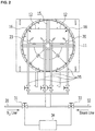
- the supplying apparatus 10 comprises a feeder main body 11 forming an accommodating space of the raw materials therein and an exit 12 for the raw materials at a lower end; a rotating shaft 13 rotatably installed at the center of the feeder main body 11; a driving unit 14 installed at the upper portion of the feeder main body and connected to the rotating shaft to rotate the rotating shaft; a blade 15 installed at the rotating shaft; an outlet 16 connected to the exit 12 and extending to the molding machine to discharge the raw materials.
- the blade 15 has an elongated bar-shaped structure, one end of which is installed at the rotating shaft and the other end of which extends in the radial direction of the rotating shaft toward the inner circumferential surface of the feeder main body. When the rotating shaft is rotated, the blade 15 provided on the rotating shaft 13 is rotated around the rotating shaft so that the raw materials stored in the feeder main body 11 are discharged through the exit 12 at the lower end of the feeder main body and supplied to the molding machine 100 through the outlet 16.
- the outlet 16 has an upper end connected to the bottom exit 12 of the cylindrical feeder main body and a lower end extending in the vertical direction toward the molding machine 100 to form a channel through which the raw materials pass through.
- the outlet 16 has a rectangular cross-sectional structure as shown in FIG. 2 .
- the outlet 16 is a narrow channel through which the raw materials pass through, and is a portion where clogging mainly occurs due to adhesiveness of the binder mixed in the raw materials.
- the raw materials supplying apparatus of the present embodiment is provided with an adjusting unit for changing the temperature of the raw materials by applying heat or cold air to the raw materials in the outlet 16.
- the adjusting unit adjusts the viscosity of the binder mixed with the raw materials to improve the flowability of the raw materials by changing the temperature of the raw materials.
- the binder mixed with water has a viscosity property that when the temperature exceeds a certain temperature, the adhesive strength is rapidly decreased and the viscosity becomes too high below a certain temperature.
- the viscosity of the binder is appropriately controlled by adjusting the temperature of the raw materials by using the viscosity property of the binder, so that the raw materials may smoothly flow without being adhered to the inside of the outlet 16.
- the adjusting unit may comprise at least one housing 20 installed at inner side of the outlet 16; a supply line connected to the housing 20 to supply high or low temperature fluid to the housing 20; and a spray nozzle 22 formed at the housing 20 for spraying the fluid to the raw materials in the outlet 16.
- the supply line comprises a nitrogen gas line 30 for supplying nitrogen gas for reducing the temperature of the raw materials; a steam line 32 for supplying steam for rising of the temperature of the raw materials; valves 31, 33 installed at the nitrogen gas line 30 and the steam line 32 to open and close each line; and a control unit 34 for controlling and operating each of the valve.
- the viscosity of the raw materials may be varied, and the flowability of the raw materials may be appropriately controlled.
- the nitrogen gas line 30 is connected to the housing 20 to supply low temperature nitrogen gas
- the steam line 32 is also connected to the housing 20 to supply high temperature steam.
- valves 31 and 33 are installed in the nitrogen gas line 30 and the steam line 32 respectively, and the valves 31 and 33 are connected to the control unit 34 and driven according to a signal of the control unit 34 to open and close the respective lines.
- the nitrogen gas line 30 and the steam line 32 may be connected to the respective housings 20 through a common line 35.
- the control unit 34 drives and controls the valves 31 and 33 according to the temperature of the raw materials in the outlet 16.
- the temperature of the raw material in the outlet 16 may be detected, for example, through a temperature sensor (not shown) installed inside the outlet 16.
- the steam supplied through the steam line 32 is sprayed to the raw materials through the spray nozzle 22 formed in the housing 20 to increase the temperature of the raw materials.
- the nitrogen gas supplied through the nitrogen gas line 30 is sprayed to the raw materials through the spray nozzle 22 formed in the housing 20 to decrease the temperature of the raw materials.
- the viscosity of the binder mixed in the raw materials is changed, and the flowability of the raw materials in the outlet 16 is improved.
- the housing 20 is formed to have a length corresponding to the vertical length of the outlet 16 and is installed in the vertical direction at the inner side of the outlet 16.
- the housing 20 may be installed at an edge of the outlet 16.
- the housing 20 may be installed respectively at every inner edge of the outlet 16 or may be installed only at an appropriate location where it can be installed, as shown in FIG. 2 .
- the installed location of the housing 20 and the number of the housing 20 may be variously set and are not particularly limited.
- the outlet 16 may be a tubular structure having a rectangular cross-sectional structure as described above, and the housing 20 may have a triangular cross-sectional structure corresponding to the shape of the inner edge of the outlet 16. Thus, the housing 20 is exactly installed closely at an edge of the outlet 16.
- the housing 20 is provided at the edge of the outlet 16 to block the edge, thereby preventing the raw materials from stagnating at the edge portion of the outlet 16. Since the edge of the outlet 16 is bent perpendicularly so that the raw materials tend to be easily stagnated at that portion, the stagnation of the raw materials may be fundamentally prevented at the edge portions by being blocked by the housing 20.
- the housing 20 is formed to extend vertically along the outlet 16, as shown in FIG. 3 .
- the housing 20 has a hollow structure with a hollow inside and a supply port 24 through which fluid is supplied to the inside is formed at one side of the housing 20 and a plurality of spray nozzles 22 are formed on the front surface, that is, the surface facing the inside of the outlet 16.
- the supply port 24 is connected to the common line 35.
- the plurality of spray nozzles are formed at the housing in the vertical direction at intervals.
- the fluid introduced into the housing 20 through the supply port 24 is sprayed to the inside of the outlet 16 through the plurality of spray nozzles 22 formed in the housing 20.
- the sizes and the forming intervals of the spray nozzles 22 can be variously set according to specifications of the facility.
- the spray nozzle 22 located at the lowest one of the spray nozzles 22 formed in the housing 20 is formed in a range D within 30 mm from the lower end to the upper portion so as to easily discharge the raw materials penetrated into the housing 20.
- the raw materials introduced into the housing 20 is easily discharged to the outside of the housing 20 through the spray nozzle 22 at the lowest end. That is, in the process of supplying the raw materials through the outlet 16, the raw materials introduced into the housing 20 through the spray nozzle 22 fall to the lower end of the housing 20 by their own weight.
- the spray nozzle 22 at the lowest end formed in the housing 20 is formed in the range D so as to be close to the lower end of the housing 20 so that the raw materials introduced into the housing 20 may be easily discharged through the lowermost spray nozzle 22.
- the location of the spray nozzle 22 at the lowest end among the spray nozzles 22 is out of the range D, the location of the spray nozzle 22 at the lower end of the housing 20 is too high so that a problem that the raw materials which are introduced into the housing 20 and fall downward cannot exit through the spray nozzle 22 occurs.
- the supplying apparatus 10 of the present embodiment improves the flowability of the raw materials by applying a physical impact to the raw materials and separating the raw materials.
- the supplying apparatus 10 may have an impact unit for applying physical impact energy to the raw material.
- the impact unit may be a physical impact energy for the raw materials and be a structure which uses the spraying pressure of nitrogen gas or steam supplied into the outlet 16 as described above.
- the impact unit may apply a physical impact to the raw materials as a separate energy other than the spraying pressure of the nitrogen gas or steam.
- the supplying apparatus may be a structure which sprays high pressure nitrogen gas and steam through the spray nozzle 22 of the housing 20 to apply physical impact energy to the raw materials.
- the nitrogen gas may be supplied through the nitrogen gas line 30 at a pressure of 8 to 16 bar. More preferably, the nitrogen gas may be supplied at a pressure of 8 to 14 bar.
- the steam may be supplied through the steam line 32 at a pressure of 8 to 16 bar. More preferably, the steam may be supplied at a pressure of 10 to 16 bar.
- nitrogen gas or steam supplied at a high pressure is sprayed to the raw materials at high pressure through the spray nozzle 22 of the housing 20.
- the pressure of the fluid sprayed through the spray nozzle 22 acts on the raw materials as impact energy.
- the raw materials are separated from the inner side of the outlet 16 by the impact applied by the fluid, and the raw materials that have not been smoothly flowed down by segregation is pushed and discharged by the impact energy of the fluid.
- the raw materials mixed the powdered coal and the binder are supplied to the molding machine through the supplying apparatus after the mixing process, and are compressed at the molding machine to manufacture coal briquettes.
- the viscosity of the binder mixed with the raw materials may be controlled or the raw materials may be impacted to improve the flowability thereof.
- the binder mixed with the raw materials may comprise a mixture of cellulose ethers such as alkylcellulose and hydroxyalkylcellulose.
- the process of adding water to the mixture of the binder and the raw materials and mixing may be subjected.
- the raw materials mixed in the form of dough are supplied to the molding machine through the raw materials supplying process by the supplying apparatus.
- the adjusting step changing the temperature of the raw materials by applying heat or cold air to the raw materials to adjust the viscosity is subjected.
- the adjusting step may change the temperature of the raw materials and adjust the viscosity by spraying high temperature steam and/or low temperature nitrogen gas to the raw materials.
- the high temperature steam acts to increase the temperature of the raw materials
- the low temperature nitrogen gas acts to decrease the temperature of the raw materials.
- FIG. 5 shows the viscosity properties according to the temperature by the concentration of the cellulose ether mixture used as a binder in this embodiment.
- the binder has the viscosity properties that the viscosity is decreased as the temperature becomes low, and the viscosity of the binder becomes low rapidly in the gel point generating temperature region, which is a specific temperature.
- the gel point may mean the temperature at which the viscosity becomes rapidly weaker and becomes gel.
- the viscosity becomes low when the temperature rises regardless of the concentration of the binder, and the viscosity is rapidly decreased at a specific temperature range of 80 to 85 °C, which is the gel point generating temperature.
- the viscosity of the raw materials becomes low or high, it is possible to prevent the adherence of the raw materials in the outlet 16 of the supplying apparatus and to improve the flowability thereof while minimizing deterioration of quality of coal briquettes.
- the control unit 34 When the temperature of the raw materials in the outlet 16 is low and the viscosity is high, the control unit 34 operates to open the valve of the steam line 32 to supply high temperature steam into the outlet 16.
- the high temperature is a temperature higher than the present temperature of the raw materials and may refer to a temperature at which the viscosity may be decreased to a desired level according to the viscosity property of the binder, for example, until before the gel point generating temperature.
- the temperature of the raw materials becomes high by spraying high temperature steam to the raw material.
- the temperature of the binder mixed in the raw materials becomes high and the viscosity becomes low.
- the flowability of the raw materials is improved and a smooth supply is achieved.
- steam may be applied according to the viscosity property of the binder to heat the raw materials to a temperature before the gel point generation from room temperature.
- the gel point generating temperature is approximately 80 to 85 °C.
- the viscosity of the cellulose ether mixture as a binder in the gel point generating temperature region becomes low rapidly, so that the viscosity of the raw materials is deteriorated.
- the temperature of the raw materials becomes high up to the gel point generating temperature, the viscosity of the raw materials is rapidly decreased, so that the quality of coal briquettes is deteriorated in the subsequent molding process.
- the flowability is not improved because the viscosity of the raw materials is high at a temperature lower than room temperature. Therefore, by increasing temperature of the raw materials to lower than the gel point generating temperature at room temperature in accordance with the viscosity property according to the temperature of the binder, the flowability of the raw materials may be improved without deteriorating the quality of coal briquettes.
- the control unit 34 operates to open the valve of the nitrogen gas line 30 to supply low temperature nitrogen gas is supplied into the outlet 16.
- the low temperature is a temperature lower than the present temperature of the raw materials and preferably may refer to a temperature lower than the range of the gel point temperature of the binder.
- the temperature of the raw materials becomes low.
- the temperature of the binder mixed in the raw materials becomes low, so that the viscosity may be recovered, and the quality of the coal briquettes may be ensured.
- the viscosity of the binder in the raw materials is adjusted by adjusting the temperature of the raw materials by spraying high temperature steam and low temperature nitrogen gas to the raw materials through the adjusting process. Therefore, when the flow of the raw materials through the outlet 16 is deteriorated, the flowability of the raw materials may be improved by decreasing the viscosity of the raw materials.
- the viscosity of the binder may be appropriately adjusted in accordance with the temperature so that the flowability of the raw materials is improved and may prevent the raw materials from stagnating, so that the raw materials are supplied more smoothly.
- the raw materials when the raw materials are already adhered or aggregated to the inner surface of the outlet 16 and is difficult to be discharged in the process of supplying the raw materials, the raw materials may be separated and discharged by applying impact energy to the raw materials.
- the process of applying the impact energy to the raw materials may be performed by spraying high temperature steam or nitrogen gas to the raw material. That is, steam or nitrogen gas sprayed for adjusting the temperature of the raw materials in the outlet 16 applies an impact to the raw material, and the raw materials are removed from the inner surface of the outlet 16 and are dropped off.
- high pressure steam or nitrogen gas may be repeatedly supplied and interrupted according to the set time.
- the impact energy is repeatedly applied to the raw material, so that the separation of the raw materials and the efficiency of discharging the aggregated raw materials may be increased.
- FIG. 6 shows a result of a comparative experiment of the raw materials supply flow of the present embodiment and conventional one.
- the present embodiment shows the raw materials supply flow results when the raw materials are supplied while the steam and nitrogen gas are sprayed into the outlet 16 of the supplying apparatus according to the present invention to produce coal briquettes.
- the comparative embodiment shows the raw materials supply flow results when producing coal briquettes under the conventional raw materials supply without steam and nitrogen gas spraying process.
- the supply flow of the raw materials was measured at the production of 40 t/h of the actual coal briquettes, and the cellulose binder was used as the binder to be mixed into the raw material, and the experiment was conducted at the condition with high moisture content of 11 wt% based on mixture.
Landscapes
- Chemical & Material Sciences (AREA)
- Organic Chemistry (AREA)
- Oil, Petroleum & Natural Gas (AREA)
- Geochemistry & Mineralogy (AREA)
- Geology (AREA)
- Life Sciences & Earth Sciences (AREA)
- General Life Sciences & Earth Sciences (AREA)
- Environmental & Geological Engineering (AREA)
- Engineering & Computer Science (AREA)
- Mechanical Engineering (AREA)
- Materials Engineering (AREA)
- Solid Fuels And Fuel-Associated Substances (AREA)
- Manufacture And Refinement Of Metals (AREA)
- Feeding, Discharge, Calcimining, Fusing, And Gas-Generation Devices (AREA)
Abstract
Description
- The present invention relates to an apparatus for manufacturing coal briquettes. More particularly, the present invention relates to a raw material supplying apparatus and a method of supplying raw materials for supplying raw materials to a molding machine of a facility for manufacturing coal briquettes.
- In a direct iron ore smelting reduction process, a reducing furnace for reducing iron ore and a melting furnace for melting the reduced iron ore are used. When the iron ore is melted in the melting furnace, coal briquettes, as a heat source for melting the iron ore, are inputted into the melting furnace. The reduced iron is melted in the melting furnace, converted into molten iron and slag, and then discharged to the outside.
- The coal briquettes should be able to increase the reaction efficiency and the heat transfer efficiency between each material by ensuring the gas permeability and the liquid permeability through which gas and liquid can smoothly pass through the melting and gasifying furnace. For this purpose, after mixing the coal with the appropriate moisture and the binder, the coal briquettes are manufactured in the form of briquettes of a predetermined size by compression-molding the mixed raw materials in the molding machine.
- At the upper portion of the molding machine, a supplying apparatus (gravity feeder) for continuously supplying the raw materials between the rolls of the molding machine is disposed. The supplying apparatus should supply the raw materials uniformly to the molding machine. For this purpose, the amount of raw materials adhered in the supplying apparatus should be small, and it should be ensured that the aggregated raw materials do not grow as it stays and that they are discharged within a proper residence time such that they do not block the exit of the supplying apparatus
- However, in the conventional supplying apparatus, in the process of supplying the raw materials to the molding machine, the moisture and the binder are mixed with each other, and the sticky raw materials are aggregated or adhered to the inside of the supplying apparatus, thereby blocking the passage frequently. As a result, the flowability of the raw materials becomes worse, continuous operation is not performed, and the quality of the coal briquettes is deteriorated.
- Particularly, when a cellulose ether compound such as alkyl cellulose or hydroxyalkyl cellulose, which is easy to use, is used as a binder of the coal briquettes in addition to molasses, the moisture content of the raw materials becomes high because water is added for use of the binder.
- Therefore, the use of the binder having high adhesion and moisture and the powdered coal comprising high moisture simultaneously causes the flow of the raw materials to become worse, and the phenomenon that the raw materials are aggregated or adhered by the binder occurs more frequently.
- The present invention provides a raw materials supplying apparatus and a method of supplying raw materials of a facility for manufacturing coal briquettes, which is for improving the supply flow of the raw materials and preventing the clogging due to the adherence or aggregation of the raw materials in the supplying apparatus.
- The present invention provides a raw material supplying apparatus and a method of supplying raw materials of a facility for manufacturing coal briquettes, which is for separating the raw materials adhered in the supplying apparatus easily and supplying to the molding machine.
- The raw materials supplying apparatus of the present embodiment is a raw materials supplying apparatus of a facility for manufacturing coal briquettes installed between a mixer for mixing a powdered coal and a binder to manufacture raw materials and a molding machine for molding the mixed raw materials to manufacture coal briquettes to supply raw materials supplied from a mixer continuously, wherein the apparatus may comprise a feeder main body forming an accommodating space of the raw materials therein and an exit for the raw materials at a lower end; a rotating shaft rotatably installed at the center of the feeder main body; a driving unit installed at the feeder main body and connected to the rotating shaft to rotate the rotating shaft; a blade installed at the rotating shaft to extend in the radial direction; an outlet connected to the exit to extend to the molding machine; and an adjusting unit changing the temperature of the raw materials by applying heat or cold air to the raw materials in the outlet to adjust the viscosity.
- The adjusting unit may comprise at least one housing installed at inner side of the outlet; a supply line connected to the housing to supply high or low temperature fluid to the housing; and a spray nozzle formed at the housing for spraying the fluid to the raw materials in the outlet.
- The supply line may comprise a nitrogen gas line for supplying nitrogen gas for reducing the temperature of the raw materials; a steam line for supplying steam for rising of the temperature of the raw materials; valves installed at the nitrogen gas line and the steam line to open and close each line; and a control unit for controlling and operating each of the valve.
- The housing may have a triangular cross-sectional structure and be a structure which is closely installed at an edge of the outlet.
- The housing may be formed to extend vertically along the outlet and the plurality of spray nozzles may be formed at the housing in the vertical direction at intervals and the spray nozzle formed at the lowest end may be formed within 30 mm from the lower end to the upper portion.
- The binder may be a mixture of cellulose ether.
- The adjusting unit may be a structure which supplies high pressure fluid through the supply line and sprays high pressure fluid through the spray nozzle of the housing to apply impact energy to the raw materials in the outlet.
- The adjusting unit is a structure which supplies the fluid at a pressure of 8 to 16 bar through the supply line.
- The raw materials supplying apparatus of the present embodiment is a raw materials supplying apparatus of a facility for manufacturing coal briquettes installed between a mixer for mixing a powdered coal and a binder to manufacture raw materials and a molding machine for molding the mixed raw materials to manufacture coal briquettes to supply raw materials supplied from a mixer continuously, the apparatus may comprise a feeder main body forming an accommodating space of the raw materials therein and an exit for the raw materials at a lower end; a rotating shaft rotatably installed at the center of the feeder main body; a driving unit installed at the feeder main body and connected to the rotating shaft to rotate the rotating shaft; a blade installed at the rotating shaft to extend in the radial direction; an outlet connected to the exit to extend to the molding machine; and an impact portion installed in the outlet to apply impact energy to raw materials in the outlet.
- The impact unit may comprise at least one housing installed at inner side of the outlet; a supply line connected to the housing to supply high pressure fluid to the housing; and a spray nozzle formed at the housing for spraying the fluid to the raw materials in the outlet.
- The supply line may comprise a nitrogen gas line for supplying high pressure nitrogen gas; and/or a steam line for supplying high pressure steam.
- The housing may have a triangular cross-sectional structure and be a structure which is closely installed at an edge of the outlet.
- The housing may be formed to extend vertically along the outlet and the plurality of spray nozzles may be formed at the housing in the vertical direction at intervals and the spray nozzle formed at the lowest end may be formed within 30 mm from the lower end to the upper portion.
- The impact unit may be a structure which supplies the fluid at a pressure of 8 to 16 bar through the supply line.
- The method of supplying raw materials of the present embodiment may comprise a mixing step mixing a powdered coal and a binder in a mixer; a supplying step supplying the mixed raw materials to a molding machine through a supplying apparatus; and a molding step compressing the raw materials with the molding machine to manufacture coal briquettes, wherein the supplying step may comprise an adjusting step changing the temperature of the raw materials by applying heat or cold air to the raw materials to adjust the viscosity.
- The adjusting step may comprise the step of spraying steam and/or a nitrogen gas to the raw materials.
- The binder may be a mixture of cellulose ether.
- The adjusting step may heat the raw materials to a temperature from room temperature up to not higher than the gel point generating temperature.
- The supplying step may further comprise an impacting step applying impact energy to the raw materials.
- The impacting step may be a structure which sprays high pressure fluid to impact the raw materials.
- The fluid may be a nitrogen gas and/or steam.
- The pressure of the fluid may be 8 to 16 bar.
- The method of supplying raw materials of the present embodiment may comprise mixing a powdered coal and a binder in a mixer; supplying the mixed raw materials to a molding machine through a supplying apparatus; and compressing the raw materials with the molding machine to manufacture coal briquettes, wherein the step of supplying the mixed raw materials to a molding machine through a supplying apparatus comprises applying impact energy to the raw materials.
- The step of applying impact energy may be a structure which sprays high pressure fluid to impact the raw materials.
- The fluid may be a nitrogen gas and/or steam.
- The pressure of the fluid may be 8 to 16 bar.
- According to the present embodiment as described above, by controlling the temperature of the raw materials by spraying low temperature nitrogen gas and high temperature steam in the process of supplying the raw materials, the viscosity of the binder is appropriately maintained so that it is possible to minimize the adherence of the raw materials inside the raw materials supplying apparatus.
- It is possible to prevent the adherence of the raw materials to the angled corners of the outlet to which the raw materials are supplied.
- By spraying high pressure fluid to the raw materials and applying the impact energy, it is possible to separate the raw materials adhered or aggregated inside the raw materials supplying apparatus easily.
- It is possible to supply the raw materials uniformly to the molding machine by preventing the adherence or clogging by segregation of the raw materials in the raw materials supplying apparatus and improving the flowability of the raw materials.
-
-
FIG. 1 is a schematic side cross-sectional view showing a raw materials supplying apparatus of the facility for manufacturing coal briquettes according to the present embodiment. -
FIG. 2 is a schematic plan sectional view showing a raw materials supplying apparatus of the facility for manufacturing coal briquettes according to the present embodiment. -
FIG. 3 is a schematic view showing the housing provided inside the raw materials supplying apparatus according to the present embodiment. -
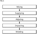
FIG. 4 is a flowchart schematically showing a raw materials supplying process according to the present embodiment. -
FIG. 5 is a graph for explaining the viscosity of the binder by the temperature of the raw materials according to the present embodiment. -
FIG. 6 is a graph showing supply flow of the raw materials according to the present embodiment in comparison with a conventional one. - The technical terms used herein are used merely for the purpose of describing a specific exemplary embodiment, and not intended to limit the present invention. Singular expressions used herein include plural expressions unless they have definitely opposite meanings. The terms "comprises" and/or "comprising" used in the specification specify particular features, regions, integers, steps, operations, elements, components, but do not preclude the presence or addition of other features, regions, integers, steps, operations, elements, and/or components thereof.
- The present invention will be described hereinafter with reference to the accompanying drawings so that those skilled in the art may easily carry out the present invention, in which exemplary embodiments of the invention are shown. As those skilled in the art would realize, the described embodiments may be modified in various different ways, all without departing from the spirit or scope of the present invention. Accordingly, the present invention may be embodied in many different forms and should not be construed as limited to the embodiments set forth herein.
-
FIG. 1 schematically shows a raw materials supplying apparatus of a facility for manufacturing coal briquettes according to the present embodiment. - The raw materials supplying apparatus of the facility for manufacturing coal briquettes of
FIG. 1 is merely for illustrating the present invention, and the present invention is not limited thereto. Therefore, it is possible to variously modify the structure of the raw materials supplying apparatus of the facility for manufacturing coal briquettes. - As shown in
FIG. 1 , a facility for manufacturing coal briquettes comprises a supplyingapparatus 10 which is installed between a mixer (not shown) for mixing a powdered coal with a binder and amolding machine 100 for producing briquettes by compression-molding the mixed raw materials and supply the raw materials from the mixer to the molding machine. - The facility for manufacturing coal briquettes may further comprise other apparatus, such as at least one kneader connected to the downstream end of the mixer for kneading the raw materials, and a transport screw for transporting the raw materials discharged from the kneader, as necessary.
- In the present embodiment, the supplying
apparatus 10 comprises a feedermain body 11 forming an accommodating space of the raw materials therein and anexit 12 for the raw materials at a lower end; arotating shaft 13 rotatably installed at the center of the feedermain body 11; a drivingunit 14 installed at the upper portion of the feeder main body and connected to the rotating shaft to rotate the rotating shaft; ablade 15 installed at the rotating shaft; anoutlet 16 connected to theexit 12 and extending to the molding machine to discharge the raw materials. Theblade 15 has an elongated bar-shaped structure, one end of which is installed at the rotating shaft and the other end of which extends in the radial direction of the rotating shaft toward the inner circumferential surface of the feeder main body. When the rotating shaft is rotated, theblade 15 provided on therotating shaft 13 is rotated around the rotating shaft so that the raw materials stored in the feedermain body 11 are discharged through theexit 12 at the lower end of the feeder main body and supplied to themolding machine 100 through theoutlet 16. - As shown in
FIG. 1 andFIG. 2 , theoutlet 16 has an upper end connected to thebottom exit 12 of the cylindrical feeder main body and a lower end extending in the vertical direction toward themolding machine 100 to form a channel through which the raw materials pass through. Theoutlet 16 has a rectangular cross-sectional structure as shown inFIG. 2 . Theoutlet 16 is a narrow channel through which the raw materials pass through, and is a portion where clogging mainly occurs due to adhesiveness of the binder mixed in the raw materials. - The raw materials supplying apparatus of the present embodiment is provided with an adjusting unit for changing the temperature of the raw materials by applying heat or cold air to the raw materials in the
outlet 16. The adjusting unit adjusts the viscosity of the binder mixed with the raw materials to improve the flowability of the raw materials by changing the temperature of the raw materials. - The binder mixed with water has a viscosity property that when the temperature exceeds a certain temperature, the adhesive strength is rapidly decreased and the viscosity becomes too high below a certain temperature. In the present embodiment, the viscosity of the binder is appropriately controlled by adjusting the temperature of the raw materials by using the viscosity property of the binder, so that the raw materials may smoothly flow without being adhered to the inside of the
outlet 16. - As shown in
FIG. 2 andFig 3 , the adjusting unit may comprise at least onehousing 20 installed at inner side of theoutlet 16; a supply line connected to thehousing 20 to supply high or low temperature fluid to thehousing 20; and aspray nozzle 22 formed at thehousing 20 for spraying the fluid to the raw materials in theoutlet 16. - The supply line comprises a
nitrogen gas line 30 for supplying nitrogen gas for reducing the temperature of the raw materials; asteam line 32 for supplying steam for rising of the temperature of the raw materials;valves nitrogen gas line 30 and thesteam line 32 to open and close each line; and acontrol unit 34 for controlling and operating each of the valve. - Accordingly, by controlling the temperature of the raw materials by spraying high temperature steam or low temperature nitrogen gas to the raw material supplied through the
outlet 16, the viscosity of the raw materials may be varied, and the flowability of the raw materials may be appropriately controlled. - As shown in
FIG. 2 , thenitrogen gas line 30 is connected to thehousing 20 to supply low temperature nitrogen gas, and thesteam line 32 is also connected to thehousing 20 to supply high temperature steam. - The
valves nitrogen gas line 30 and thesteam line 32 respectively, and thevalves control unit 34 and driven according to a signal of thecontrol unit 34 to open and close the respective lines. In the present embodiment, thenitrogen gas line 30 and thesteam line 32 may be connected to therespective housings 20 through acommon line 35. - The
control unit 34 drives and controls thevalves outlet 16. The temperature of the raw material in theoutlet 16 may be detected, for example, through a temperature sensor (not shown) installed inside theoutlet 16. - The steam supplied through the
steam line 32 is sprayed to the raw materials through thespray nozzle 22 formed in thehousing 20 to increase the temperature of the raw materials. In contrast, the nitrogen gas supplied through thenitrogen gas line 30 is sprayed to the raw materials through thespray nozzle 22 formed in thehousing 20 to decrease the temperature of the raw materials. - By adjusting the temperature of the raw materials, the viscosity of the binder mixed in the raw materials is changed, and the flowability of the raw materials in the
outlet 16 is improved. - In the present embodiment, the
housing 20 is formed to have a length corresponding to the vertical length of theoutlet 16 and is installed in the vertical direction at the inner side of theoutlet 16. Thehousing 20 may be installed at an edge of theoutlet 16. Thehousing 20 may be installed respectively at every inner edge of theoutlet 16 or may be installed only at an appropriate location where it can be installed, as shown inFIG. 2 . The installed location of thehousing 20 and the number of thehousing 20 may be variously set and are not particularly limited. - The
outlet 16 may be a tubular structure having a rectangular cross-sectional structure as described above, and thehousing 20 may have a triangular cross-sectional structure corresponding to the shape of the inner edge of theoutlet 16. Thus, thehousing 20 is exactly installed closely at an edge of theoutlet 16. - Accordingly, the
housing 20 is provided at the edge of theoutlet 16 to block the edge, thereby preventing the raw materials from stagnating at the edge portion of theoutlet 16. Since the edge of theoutlet 16 is bent perpendicularly so that the raw materials tend to be easily stagnated at that portion, the stagnation of the raw materials may be fundamentally prevented at the edge portions by being blocked by thehousing 20. - The
housing 20 is formed to extend vertically along theoutlet 16, as shown inFIG. 3 . Thehousing 20 has a hollow structure with a hollow inside and asupply port 24 through which fluid is supplied to the inside is formed at one side of thehousing 20 and a plurality ofspray nozzles 22 are formed on the front surface, that is, the surface facing the inside of theoutlet 16. Thesupply port 24 is connected to thecommon line 35. The plurality of spray nozzles are formed at the housing in the vertical direction at intervals. The fluid introduced into thehousing 20 through thesupply port 24 is sprayed to the inside of theoutlet 16 through the plurality ofspray nozzles 22 formed in thehousing 20. The sizes and the forming intervals of thespray nozzles 22 can be variously set according to specifications of the facility. - In the present embodiment, the
spray nozzle 22 located at the lowest one of thespray nozzles 22 formed in thehousing 20 is formed in a range D within 30 mm from the lower end to the upper portion so as to easily discharge the raw materials penetrated into thehousing 20. - Thus, the raw materials introduced into the
housing 20 is easily discharged to the outside of thehousing 20 through thespray nozzle 22 at the lowest end. That is, in the process of supplying the raw materials through theoutlet 16, the raw materials introduced into thehousing 20 through thespray nozzle 22 fall to the lower end of thehousing 20 by their own weight. Thespray nozzle 22 at the lowest end formed in thehousing 20 is formed in the range D so as to be close to the lower end of thehousing 20 so that the raw materials introduced into thehousing 20 may be easily discharged through thelowermost spray nozzle 22. When the location of thespray nozzle 22 at the lowest end among thespray nozzles 22 is out of the range D, the location of thespray nozzle 22 at the lower end of thehousing 20 is too high so that a problem that the raw materials which are introduced into thehousing 20 and fall downward cannot exit through thespray nozzle 22 occurs. - Here, when the raw materials passing through the
outlet 16 are aggregated and adhered to the inside of theoutlet 16, the supplyingapparatus 10 of the present embodiment improves the flowability of the raw materials by applying a physical impact to the raw materials and separating the raw materials. - For this purpose, the supplying
apparatus 10 may have an impact unit for applying physical impact energy to the raw material. In case of this embodiment, the impact unit may be a physical impact energy for the raw materials and be a structure which uses the spraying pressure of nitrogen gas or steam supplied into theoutlet 16 as described above. The impact unit may apply a physical impact to the raw materials as a separate energy other than the spraying pressure of the nitrogen gas or steam. - The supplying apparatus may be a structure which sprays high pressure nitrogen gas and steam through the
spray nozzle 22 of thehousing 20 to apply physical impact energy to the raw materials. - In this embodiment, the nitrogen gas may be supplied through the
nitrogen gas line 30 at a pressure of 8 to 16 bar. More preferably, the nitrogen gas may be supplied at a pressure of 8 to 14 bar. In addition, the steam may be supplied through thesteam line 32 at a pressure of 8 to 16 bar. More preferably, the steam may be supplied at a pressure of 10 to 16 bar. - When the pressure of the fluid such as nitrogen gas or steam is lower than the above range, the impact energy due to the fluid is too weak to obtain the separation effect of the raw materials and when being higher than the above range, there is a problem that the cost according to high pressure rises while increasing of the effect of discharge of the raw materials is not great.
- Like this, nitrogen gas or steam supplied at a high pressure is sprayed to the raw materials at high pressure through the
spray nozzle 22 of thehousing 20. The pressure of the fluid sprayed through thespray nozzle 22 acts on the raw materials as impact energy. - Thus, the raw materials are separated from the inner side of the
outlet 16 by the impact applied by the fluid, and the raw materials that have not been smoothly flowed down by segregation is pushed and discharged by the impact energy of the fluid. - Hereinafter, the raw materials supply process through the raw materials supplying apparatus of the present embodiment will be described with reference to
FIG. 4 . - The raw materials mixed the powdered coal and the binder are supplied to the molding machine through the supplying apparatus after the mixing process, and are compressed at the molding machine to manufacture coal briquettes. In the process of supplying the raw materials to the molding machine, the viscosity of the binder mixed with the raw materials may be controlled or the raw materials may be impacted to improve the flowability thereof.
- In this embodiment, the binder mixed with the raw materials may comprise a mixture of cellulose ethers such as alkylcellulose and hydroxyalkylcellulose. When the cellulose ether mixture is comprised as a binder, the process of adding water to the mixture of the binder and the raw materials and mixing may be subjected. The raw materials mixed in the form of dough are supplied to the molding machine through the raw materials supplying process by the supplying apparatus.
- According to this embodiment, in order to smoothly and uniformly supply the raw materials in the raw materials supplying process, the adjusting step changing the temperature of the raw materials by applying heat or cold air to the raw materials to adjust the viscosity is subjected.
- The adjusting step may change the temperature of the raw materials and adjust the viscosity by spraying high temperature steam and/or low temperature nitrogen gas to the raw materials. The high temperature steam acts to increase the temperature of the raw materials, and the low temperature nitrogen gas acts to decrease the temperature of the raw materials.
-
FIG. 5 shows the viscosity properties according to the temperature by the concentration of the cellulose ether mixture used as a binder in this embodiment. The binder has the viscosity properties that the viscosity is decreased as the temperature becomes low, and the viscosity of the binder becomes low rapidly in the gel point generating temperature region, which is a specific temperature. The gel point may mean the temperature at which the viscosity becomes rapidly weaker and becomes gel. - As shown in
FIG. 5 , in the case of the cellulose ether mixture, it may be confirmed that the viscosity becomes low when the temperature rises regardless of the concentration of the binder, and the viscosity is rapidly decreased at a specific temperature range of 80 to 85 °C, which is the gel point generating temperature. - When the raw materials are heated or cooled until before the gel point generation according to this viscosity property of the binder, the viscosity of the raw materials becomes low or high, it is possible to prevent the adherence of the raw materials in the
outlet 16 of the supplying apparatus and to improve the flowability thereof while minimizing deterioration of quality of coal briquettes. - That is, to increase the temperature of the raw materials by supplying high temperature steam to the raw materials or to decrease the temperature of the raw materials by spraying low temperature nitrogen gas in the adjusting process.
- When the temperature of the raw materials in the
outlet 16 is low and the viscosity is high, thecontrol unit 34 operates to open the valve of thesteam line 32 to supply high temperature steam into theoutlet 16. The high temperature is a temperature higher than the present temperature of the raw materials and may refer to a temperature at which the viscosity may be decreased to a desired level according to the viscosity property of the binder, for example, until before the gel point generating temperature. Like this, the temperature of the raw materials becomes high by spraying high temperature steam to the raw material. As a result, the temperature of the binder mixed in the raw materials becomes high and the viscosity becomes low. As the viscosity decreases, the flowability of the raw materials is improved and a smooth supply is achieved. - In the case of this embodiment, steam may be applied according to the viscosity property of the binder to heat the raw materials to a temperature before the gel point generation from room temperature. As shown in
Fig. 5 , in the case of the binder being a cellulose ether mixture, the gel point generating temperature is approximately 80 to 85 °C. The viscosity of the cellulose ether mixture as a binder in the gel point generating temperature region becomes low rapidly, so that the viscosity of the raw materials is deteriorated. When the temperature of the raw materials becomes high up to the gel point generating temperature, the viscosity of the raw materials is rapidly decreased, so that the quality of coal briquettes is deteriorated in the subsequent molding process. In addition, the flowability is not improved because the viscosity of the raw materials is high at a temperature lower than room temperature. Therefore, by increasing temperature of the raw materials to lower than the gel point generating temperature at room temperature in accordance with the viscosity property according to the temperature of the binder, the flowability of the raw materials may be improved without deteriorating the quality of coal briquettes. - In the process of improving the flowability of the raw material, when after the flowability of the raw materials is improved due to high temperature steam spraying or when the temperature of the raw materials becomes too high, the
control unit 34 operates to open the valve of thenitrogen gas line 30 to supply low temperature nitrogen gas is supplied into theoutlet 16. The low temperature is a temperature lower than the present temperature of the raw materials and preferably may refer to a temperature lower than the range of the gel point temperature of the binder. - By spraying low temperature nitrogen gas to the raw material, the temperature of the raw materials becomes low. Thus, the temperature of the binder mixed in the raw materials becomes low, so that the viscosity may be recovered, and the quality of the coal briquettes may be ensured.
- Like this, the viscosity of the binder in the raw materials is adjusted by adjusting the temperature of the raw materials by spraying high temperature steam and low temperature nitrogen gas to the raw materials through the adjusting process. Therefore, when the flow of the raw materials through the
outlet 16 is deteriorated, the flowability of the raw materials may be improved by decreasing the viscosity of the raw materials. - Thus, the viscosity of the binder may be appropriately adjusted in accordance with the temperature so that the flowability of the raw materials is improved and may prevent the raw materials from stagnating, so that the raw materials are supplied more smoothly.
- In addition, when the raw materials are already adhered or aggregated to the inner surface of the
outlet 16 and is difficult to be discharged in the process of supplying the raw materials, the raw materials may be separated and discharged by applying impact energy to the raw materials. - In this embodiment, the process of applying the impact energy to the raw materials may be performed by spraying high temperature steam or nitrogen gas to the raw material. That is, steam or nitrogen gas sprayed for adjusting the temperature of the raw materials in the
outlet 16 applies an impact to the raw material, and the raw materials are removed from the inner surface of theoutlet 16 and are dropped off. - In the process of applying the impact energy to the raw material, high pressure steam or nitrogen gas may be repeatedly supplied and interrupted according to the set time. As the high pressure fluid spraying is repeatedly performed, the impact energy is repeatedly applied to the raw material, so that the separation of the raw materials and the efficiency of discharging the aggregated raw materials may be increased.
-
FIG. 6 shows a result of a comparative experiment of the raw materials supply flow of the present embodiment and conventional one. - In
FIG. 6 , the present embodiment shows the raw materials supply flow results when the raw materials are supplied while the steam and nitrogen gas are sprayed into theoutlet 16 of the supplying apparatus according to the present invention to produce coal briquettes. The comparative embodiment shows the raw materials supply flow results when producing coal briquettes under the conventional raw materials supply without steam and nitrogen gas spraying process. - In the present embodiment and comparative embodiment, the supply flow of the raw materials was measured at the production of 40 t/h of the actual coal briquettes, and the cellulose binder was used as the binder to be mixed into the raw material, and the experiment was conducted at the condition with high moisture content of 11 wt% based on mixture.
- The experimental results as shown in
FIG. 6 , in case of comparative embodiment, 4 times of the raw materials clogging occurred for 4 hours, but in case of the embodiment, only one clogging occurred for 8 hours. - As described above, in case of the present embodiment, by spraying high pressure nitrogen gas or steam into the
outlet 16, it is possible to prevent the raw materials from the clogging in the supplying apparatus and to improve the flowability of the raw material. - While this invention has been described in connection with what is presently considered to be practical exemplary embodiments, it is to be understood that the invention is not limited to the disclosed embodiments, but, on the contrary, is intended to cover various modifications and equivalent arrangements included within the spirit and scope of the appended claims.
Claims (24)
- A raw materials supplying apparatus of a facility for manufacturing coal briquettes installed between a mixer for mixing a powdered coal and a binder to manufacture raw materials and a molding machine for molding the mixed raw materials to manufacture coal briquettes to supply raw materials supplied from a mixer continuously, the apparatus comprising:
a feeder main body forming an accommodating space of the raw materials therein and an exit for the raw materials at a lower end; a rotating shaft rotatably installed at the center of the feeder main body; a driving unit installed at the feeder main body and connected to the rotating shaft to rotate the rotating shaft; a blade installed at the rotating shaft to extend in the radial direction; an outlet connected to the exit to extend to the molding machine; and an adjusting unit changing the temperature of the raw materials by applying heat or cold air to the raw materials in the outlet to adjust the viscosity. - The apparatus of claim 1, wherein
the adjusting unit comprises at least one housing installed at inner side of the outlet; a supply line connected to the housing to supply high or low temperature fluid to the housing; and a spray nozzle formed at the housing for spraying the fluid to the raw materials in the outlet. - The apparatus of claim 2, wherein
the supply line comprises a nitrogen gas line for supplying nitrogen gas for reducing the temperature of the raw materials; a steam line for supplying steam for rising of the temperature of the raw materials; Valves installed at the nitrogen gas line and the steam line to open and close each line; and a control unit for controlling and operating each of the valve. - The apparatus of claim 3, wherein
the housing has a triangular cross-sectional structure and is a structure which is closely installed at an edge of the outlet. - The apparatus of claim 3, wherein
the housing is formed to extend vertically along the outlet and the plurality of spray nozzles are formed at the housing in the vertical direction at intervals and the spray nozzle formed at the lowest end is formed within 30 mm from the lower end to the upper portion. - The apparatus of any of claims 1 to 5, wherein
the adjusting unit is a structure which supplies high pressure fluid through the supply line and sprays high pressure fluid through the spray nozzle of the housing to apply impact energy to the raw materials in the outlet. - The apparatus of claim 6, wherein
the adjusting unit is a structure which supplies the fluid at a pressure of 8 to 16 bar through the supply line. - A raw materials supplying apparatus of a facility for manufacturing coal briquettes installed between a mixer for mixing a powdered coal and a binder to manufacture raw materials and a molding machine for molding the mixed raw materials to manufacture coal briquettes to supply raw materials supplied from a mixer continuously, the apparatus comprising:
a feeder main body forming an accommodating space of the raw materials therein and an exit for the raw materials at a lower end; a rotating shaft rotatably installed at the center of the feeder main body; a driving unit installed at the upper portion of the feeder main body and connected to the rotating shaft to rotate the rotating shaft; a blade installed at the rotating shaft to extend in the radial direction; an outlet connected to the exit to extend to the molding machine; and an impact portion installed in the outlet to apply impact energy to raw materials in the outlet. - The apparatus of claim 8, wherein
the impact unit comprises at least one housing installed at inner side of the outlet; a supply line connected to the housing to supply high pressure fluid to the housing; and a spray nozzle formed at the housing for spraying the fluid to the raw materials in the outlet. - The apparatus of claim 9, wherein
the supply line comprises a nitrogen gas line for supplying high pressure nitrogen gas; and/or a steam line for supplying high pressure steam. - The apparatus of claim 10, wherein
the housing has a triangular cross-sectional structure and is a structure which is closely installed at an edge of the outlet. - The apparatus of claim 10, wherein
the housing is formed to extend vertically along the outlet and the plurality of spray nozzles are formed at the housing in the vertical direction at intervals and the spray nozzle formed at the lowest end is formed within 30 mm from the lower end to the upper portion. - The apparatus of claim 10, wherein
the impact unit is a structure which supplies the fluid at a pressure of 8 to 16 bar through the supply line. - A method of supplying raw materials of a facility for manufacturing coal briquettes comprising:a mixing step mixing a powdered coal and a binder in a mixer; a supplying step supplying the mixed raw materials to a molding machine through a supplying apparatus; and a molding step compressing the raw materials with the molding machine to manufacture coal briquettes,wherein the supplying step comprises an adjusting step changing the temperature of the raw materials by applying heat or cold air to the raw materials to adjust the viscosity.
- The method of claim 14, wherein
the adjusting step comprises the step of spraying steam and/or a nitrogen gas to the raw materials. - The method of claim 15, wherein
the binder is a mixture of cellulose ether, and the adjusting step is heating at a temperature from room temperature up to not higher than the gel point generating temperature of the binder by spraying steam to the raw materials. - The method of any of claims 14 to 16, wherein
the supplying step further comprises an impacting step applying impact energy to the raw materials. - The method of claim 17, wherein
the impacting step is a structure which sprays high pressure fluid to impact the raw materials. - The method of claim 18, wherein
the fluid is a nitrogen gas and/or steam. - The method of claim 19, wherein
the pressure of the fluid is 8 to 16 bar. - A method of supplying raw materials of a facility for manufacturing coal briquettes comprising:mixing a powdered coal and a binder in a mixer; supplying the mixed raw materials to a molding machine through a supplying apparatus; and compressing the raw materials with the molding machine to manufacture coal briquettes,wherein the step of supplying the mixed raw materials to a molding machine through a supplying apparatus comprises applying impact energy to the raw materials.
- The method of claim 21, wherein
the step of applying impact energy is a structure which sprays high pressure fluid to impact the raw materials. - The method of claim 22, wherein
the fluid is a nitrogen gas and/or steam. - The method of claim 23, wherein
the pressure of the fluid is 8 to 16 bar.
Applications Claiming Priority (2)
| Application Number | Priority Date | Filing Date | Title |
|---|---|---|---|
| KR1020160110097A KR101839959B1 (en) | 2016-08-29 | 2016-08-29 | Gravity feeder for coal briquettes manufacturing apparatus and method for feeding material of gravity feeder |
| PCT/KR2017/006683 WO2018043893A1 (en) | 2016-08-29 | 2017-06-26 | Raw material supply device and raw material supply method for coal briquette manufacturing equipment |
Publications (2)
| Publication Number | Publication Date |
|---|---|
| EP3505600A1 true EP3505600A1 (en) | 2019-07-03 |
| EP3505600A4 EP3505600A4 (en) | 2019-10-02 |
Family
ID=61301225
Family Applications (1)
| Application Number | Title | Priority Date | Filing Date |
|---|---|---|---|
| EP17846818.7A Withdrawn EP3505600A4 (en) | 2016-08-29 | 2017-06-26 | Raw material supply device and raw material supply method for coal briquette manufacturing equipment |
Country Status (4)
| Country | Link |
|---|---|
| EP (1) | EP3505600A4 (en) |
| KR (1) | KR101839959B1 (en) |
| CN (1) | CN109844067A (en) |
| WO (1) | WO2018043893A1 (en) |
Family Cites Families (19)
| Publication number | Priority date | Publication date | Assignee | Title |
|---|---|---|---|---|
| DE560881C (en) * | 1931-02-10 | 1932-10-07 | Koeppern & Co Kg Maschf | Filling container for roller presses for the production of briquettes from hard coal dust and crushed hard pitch as a binding agent |
| DE1026210B (en) * | 1955-03-01 | 1958-03-13 | Koeppern & Co K G Maschf | Allocation device for the delivery of the briquetting material on briquette presses |
| DE1060302B (en) * | 1957-07-10 | 1959-06-25 | Impact Mixing Corp | Method and device for pressing briquettes |
| SU902938A1 (en) * | 1980-06-24 | 1982-02-07 | Конструкторско-технологическое бюро | Apparatus for feeding strip and material into working zone of working machine |
| KR100332913B1 (en) * | 1997-12-22 | 2002-07-18 | 이구택 | Coal briquetting method with plastic binder and device thereof |
| KR101017714B1 (en) * | 2006-04-27 | 2011-02-25 | 신닛뽄세이테쯔 카부시키카이샤 | Waste Plastic Forming Method and Waste Plastic Pyrolysis Method |
| JP5010871B2 (en) * | 2006-08-09 | 2012-08-29 | 新日本製鐵株式会社 | Pusher for roll compactor |
| CN1962251B (en) * | 2006-11-20 | 2010-11-10 | 苏光宝 | Feeding mechanism of powder molding press |
| CN101015963B (en) * | 2007-02-16 | 2011-08-17 | 苏长春 | Constant feeding mechanism for powder molding press |
| CN201645867U (en) * | 2010-01-12 | 2010-11-24 | 汪淼 | Renewable carbon production machine |
| KR20120008588A (en) * | 2010-07-19 | 2012-02-01 | 진일플랜텍 주식회사 | Coal forming device |
| KR20130097919A (en) * | 2012-02-27 | 2013-09-04 | 코텍엔지니어링 주식회사 | A coal briquette, a manufacturing apparatus and a manufacturing method thereof |
| KR101473961B1 (en) * | 2013-01-31 | 2014-12-17 | 성안이엔티주식회사 | Selected from the landfill of combustible fuel manufacturing high-purity method and device |
| JP5985433B2 (en) * | 2013-04-24 | 2016-09-06 | 株式会社神戸製鋼所 | Method for producing molded solid fuel |
| DE102013109405A1 (en) * | 2013-08-29 | 2015-03-05 | Rwe Power Ag | Method of forming molded articles from a granular material and corresponding roller press |
| KR101674888B1 (en) * | 2014-12-19 | 2016-11-10 | 주식회사 포스코 | Gravity feeder for coal briquettes manufacturing apparatus |
| CN105861090B (en) * | 2016-03-31 | 2019-01-11 | 神华集团有限责任公司 | A kind of pulverized coal forming device and forming method |
| CN206334550U (en) * | 2016-12-16 | 2017-07-18 | 广州市威士环保科技有限公司 | A kind of chemicals dosing plant |
| CN206661100U (en) * | 2017-03-13 | 2017-11-24 | 溧阳市鸿岳机械制造有限公司 | A kind of novel feed mixing machine |
-
2016
- 2016-08-29 KR KR1020160110097A patent/KR101839959B1/en not_active Expired - Fee Related
-
2017
- 2017-06-26 EP EP17846818.7A patent/EP3505600A4/en not_active Withdrawn
- 2017-06-26 WO PCT/KR2017/006683 patent/WO2018043893A1/en not_active Ceased
- 2017-06-26 CN CN201780064068.8A patent/CN109844067A/en active Pending
Also Published As
| Publication number | Publication date |
|---|---|
| CN109844067A (en) | 2019-06-04 |
| WO2018043893A1 (en) | 2018-03-08 |
| KR20180024250A (en) | 2018-03-08 |
| EP3505600A4 (en) | 2019-10-02 |
| KR101839959B1 (en) | 2018-03-19 |
Similar Documents
| Publication | Publication Date | Title |
|---|---|---|
| EP2338590A1 (en) | Resin production apparatus and resin production method | |
| JP5316403B2 (en) | Powder kneading method and apparatus, and powder agglomeration method | |
| CN108889549A (en) | A kind of coating die head with differential flow adjustment structure | |
| CN209271275U (en) | A kind of processing unit (plant) of hot melt adhesive | |
| KR20170117530A (en) | Tundish arrangements and nozzles for granulation of molten material | |
| WO2008098706A1 (en) | Dosing and/or transport of powdery and/or pourable solids | |
| RS61882B1 (en) | Device and method for producing pulverulent plastics with a spherical structure | |
| UA96143C2 (en) | Charging device for shaft furnace, blast furnace comprising thereof and method for centering of starting material in blast funace | |
| US20140245793A1 (en) | Process And Apparatus For Refining Molten Glass | |
| CN218359086U (en) | Pressure type countercurrent cooling spray granulation system | |
| JP2016507227A (en) | Device and method for discharging a dough body that is metered and shaped from a pumpable dough | |
| CN113413810B (en) | Mixing device for nano powder material | |
| KR101839959B1 (en) | Gravity feeder for coal briquettes manufacturing apparatus and method for feeding material of gravity feeder | |
| CN107570277B (en) | Production line of inorganic adhesive of electronic paste | |
| CN114953395B (en) | Forced feeding device for PVB explosion-proof film production and application method thereof | |
| KR101674888B1 (en) | Gravity feeder for coal briquettes manufacturing apparatus | |
| CN107362749B (en) | Method and apparatus for granulation with pressure control | |
| CN206011431U (en) | A kind of ceramic capacitor dielectric porcelain damping device | |
| CN1569320A (en) | Particle size controllable spouting granulation method and apparatus | |
| CN109806810B (en) | Method and equipment for stabilizing production of fertilizer particles | |
| JP6880948B2 (en) | Nozzle device | |
| CN206068978U (en) | The system that powder is crushed | |
| CN204823017U (en) | Automatic unloading system | |
| CN204751502U (en) | Soft magnetic ferrite magnetic core blank material conveying equipment | |
| CN203805170U (en) | Rubber material granulation apparatus |
Legal Events
| Date | Code | Title | Description |
|---|---|---|---|
| PUAI | Public reference made under article 153(3) epc to a published international application that has entered the european phase |
Free format text: ORIGINAL CODE: 0009012 |
|
| 17P | Request for examination filed |
Effective date: 20190329 |
|
| AK | Designated contracting states |
Kind code of ref document: A1 Designated state(s): AL AT BE BG CH CY CZ DE DK EE ES FI FR GB GR HR HU IE IS IT LI LT LU LV MC MK MT NL NO PL PT RO RS SE SI SK SM TR |
|
| AX | Request for extension of the european patent |
Extension state: BA ME |
|
| A4 | Supplementary search report drawn up and despatched |
Effective date: 20190830 |
|
| RIC1 | Information provided on ipc code assigned before grant |
Ipc: C10L 5/04 20060101ALI20190826BHEP Ipc: C10L 5/10 20060101AFI20190826BHEP Ipc: B30B 15/30 20060101ALI20190826BHEP Ipc: C10L 5/22 20060101ALI20190826BHEP Ipc: C10L 5/14 20060101ALI20190826BHEP Ipc: C10L 5/36 20060101ALI20190826BHEP |
|
| DAV | Request for validation of the european patent (deleted) | ||
| DAX | Request for extension of the european patent (deleted) | ||
| GRAP | Despatch of communication of intention to grant a patent |
Free format text: ORIGINAL CODE: EPIDOSNIGR1 |
|
| STAA | Information on the status of an ep patent application or granted ep patent |
Free format text: STATUS: GRANT OF PATENT IS INTENDED |
|
| RIC1 | Information provided on ipc code assigned before grant |
Ipc: B30B 15/34 20060101ALI20200519BHEP Ipc: B30B 15/30 20060101ALI20200519BHEP Ipc: C10L 5/04 20060101ALI20200519BHEP Ipc: C10L 5/22 20060101ALI20200519BHEP Ipc: C10L 5/14 20060101ALI20200519BHEP Ipc: C10L 5/10 20060101AFI20200519BHEP Ipc: C10L 5/36 20060101ALI20200519BHEP Ipc: B30B 11/16 20060101ALI20200519BHEP |
|
| INTG | Intention to grant announced |
Effective date: 20200612 |
|
| STAA | Information on the status of an ep patent application or granted ep patent |
Free format text: STATUS: THE APPLICATION IS DEEMED TO BE WITHDRAWN |
|
| 18D | Application deemed to be withdrawn |
Effective date: 20201023 |