EP3505435B1 - Heat dissipation structure of axle shaft for power wheel of electric motorcycle - Google Patents
Heat dissipation structure of axle shaft for power wheel of electric motorcycle Download PDFInfo
- Publication number
- EP3505435B1 EP3505435B1 EP18197929.5A EP18197929A EP3505435B1 EP 3505435 B1 EP3505435 B1 EP 3505435B1 EP 18197929 A EP18197929 A EP 18197929A EP 3505435 B1 EP3505435 B1 EP 3505435B1
- Authority
- EP
- European Patent Office
- Prior art keywords
- tubular section
- thermal conduction
- conduction element
- shaft body
- power wheel
- Prior art date
- Legal status (The legal status is an assumption and is not a legal conclusion. Google has not performed a legal analysis and makes no representation as to the accuracy of the status listed.)
- Active
Links
Images




Classifications
-
- B—PERFORMING OPERATIONS; TRANSPORTING
- B62—LAND VEHICLES FOR TRAVELLING OTHERWISE THAN ON RAILS
- B62K—CYCLES; CYCLE FRAMES; CYCLE STEERING DEVICES; RIDER-OPERATED TERMINAL CONTROLS SPECIALLY ADAPTED FOR CYCLES; CYCLE AXLE SUSPENSIONS; CYCLE SIDECARS, FORECARS, OR THE LIKE
- B62K25/00—Axle suspensions
- B62K25/005—Axle suspensions characterised by the axle being supported at one end only
-
- B—PERFORMING OPERATIONS; TRANSPORTING
- B60—VEHICLES IN GENERAL
- B60K—ARRANGEMENT OR MOUNTING OF PROPULSION UNITS OR OF TRANSMISSIONS IN VEHICLES; ARRANGEMENT OR MOUNTING OF PLURAL DIVERSE PRIME-MOVERS IN VEHICLES; AUXILIARY DRIVES FOR VEHICLES; INSTRUMENTATION OR DASHBOARDS FOR VEHICLES; ARRANGEMENTS IN CONNECTION WITH COOLING, AIR INTAKE, GAS EXHAUST OR FUEL SUPPLY OF PROPULSION UNITS IN VEHICLES
- B60K7/00—Disposition of motor in, or adjacent to, traction wheel
- B60K7/0007—Disposition of motor in, or adjacent to, traction wheel the motor being electric
-
- B—PERFORMING OPERATIONS; TRANSPORTING
- B62—LAND VEHICLES FOR TRAVELLING OTHERWISE THAN ON RAILS
- B62K—CYCLES; CYCLE FRAMES; CYCLE STEERING DEVICES; RIDER-OPERATED TERMINAL CONTROLS SPECIALLY ADAPTED FOR CYCLES; CYCLE AXLE SUSPENSIONS; CYCLE SIDECARS, FORECARS, OR THE LIKE
- B62K25/00—Axle suspensions
- B62K25/02—Axle suspensions for mounting axles rigidly on cycle frame or fork, e.g. adjustably
-
- B—PERFORMING OPERATIONS; TRANSPORTING
- B62—LAND VEHICLES FOR TRAVELLING OTHERWISE THAN ON RAILS
- B62K—CYCLES; CYCLE FRAMES; CYCLE STEERING DEVICES; RIDER-OPERATED TERMINAL CONTROLS SPECIALLY ADAPTED FOR CYCLES; CYCLE AXLE SUSPENSIONS; CYCLE SIDECARS, FORECARS, OR THE LIKE
- B62K25/00—Axle suspensions
- B62K25/04—Axle suspensions for mounting axles resiliently on cycle frame or fork
- B62K25/28—Axle suspensions for mounting axles resiliently on cycle frame or fork with pivoted chain-stay
- B62K25/283—Axle suspensions for mounting axles resiliently on cycle frame or fork with pivoted chain-stay for cycles without a pedal crank, e.g. motorcycles
-
- B—PERFORMING OPERATIONS; TRANSPORTING
- B62—LAND VEHICLES FOR TRAVELLING OTHERWISE THAN ON RAILS
- B62M—RIDER PROPULSION OF WHEELED VEHICLES OR SLEDGES; POWERED PROPULSION OF SLEDGES OR SINGLE-TRACK CYCLES; TRANSMISSIONS SPECIALLY ADAPTED FOR SUCH VEHICLES
- B62M23/00—Transmissions characterised by use of other elements; Other transmissions
- B62M23/02—Transmissions characterised by use of other elements; Other transmissions characterised by the use of two or more dissimilar sources of power, e.g. transmissions for hybrid motorcycles
-
- B—PERFORMING OPERATIONS; TRANSPORTING
- B62—LAND VEHICLES FOR TRAVELLING OTHERWISE THAN ON RAILS
- B62M—RIDER PROPULSION OF WHEELED VEHICLES OR SLEDGES; POWERED PROPULSION OF SLEDGES OR SINGLE-TRACK CYCLES; TRANSMISSIONS SPECIALLY ADAPTED FOR SUCH VEHICLES
- B62M7/00—Motorcycles characterised by position of motor or engine
- B62M7/12—Motorcycles characterised by position of motor or engine with the engine beside or within the driven wheel
-
- B—PERFORMING OPERATIONS; TRANSPORTING
- B60—VEHICLES IN GENERAL
- B60K—ARRANGEMENT OR MOUNTING OF PROPULSION UNITS OR OF TRANSMISSIONS IN VEHICLES; ARRANGEMENT OR MOUNTING OF PLURAL DIVERSE PRIME-MOVERS IN VEHICLES; AUXILIARY DRIVES FOR VEHICLES; INSTRUMENTATION OR DASHBOARDS FOR VEHICLES; ARRANGEMENTS IN CONNECTION WITH COOLING, AIR INTAKE, GAS EXHAUST OR FUEL SUPPLY OF PROPULSION UNITS IN VEHICLES
- B60K7/00—Disposition of motor in, or adjacent to, traction wheel
- B60K2007/0092—Disposition of motor in, or adjacent to, traction wheel the motor axle being coaxial to the wheel axle
-
- B—PERFORMING OPERATIONS; TRANSPORTING
- B62—LAND VEHICLES FOR TRAVELLING OTHERWISE THAN ON RAILS
- B62K—CYCLES; CYCLE FRAMES; CYCLE STEERING DEVICES; RIDER-OPERATED TERMINAL CONTROLS SPECIALLY ADAPTED FOR CYCLES; CYCLE AXLE SUSPENSIONS; CYCLE SIDECARS, FORECARS, OR THE LIKE
- B62K2204/00—Adaptations for driving cycles by electric motor
Definitions
- the present invention has arisen to mitigate and/or obviate the afore-described disadvantages.
- the first tubular section has two planes formed on an outer wall thereof, each of the two planes is symmetrical relative to the center of the first tubular section so that it can be clamped by a wrench or other hand tools, hence the thermal conduction element (20) is rotated to connect with or remove from the support rack (32).
Landscapes
- Engineering & Computer Science (AREA)
- Mechanical Engineering (AREA)
- Chemical & Material Sciences (AREA)
- Combustion & Propulsion (AREA)
- Transportation (AREA)
- Motor Or Generator Cooling System (AREA)
- Arrangement Or Mounting Of Propulsion Units For Vehicles (AREA)
Description
- The present invention relates to a power wheel axle shaft of an electronic motorcycle having a heat dissipation structure.
- A hub motor of a conventional electronic motorcycle drives a wheel.
- The hub motor is typically an outer rotation motor and has a stator which contains a support rack and multiple coil sets. Each of the multiple coil sets is arranged around an outer wall of the support rack, an axle shaft of the power wheel is connected to the support rack, and a rotor of the hub motor is connected to a rim of the power wheel. The rim produces thermal energy, and dust, objects, and rain are stopped from entering the hub motor. The thermal energy conducts the heat to the support rack and the axle shaft from the rim so that the temperature of the support rack and the axle shaft increases, thus reducing the service life of the axle shaft.
- One form of integrated hub motor is described in Specification No.
WO 2010/124624 , which discloses all of the features of the preamble ofclaim 1, but this also has a number of disadvantages. - The present invention has arisen to mitigate and/or obviate the afore-described disadvantages.
- The primary objective of the present invention is to provide a heat dissipation structure of a power wheel axle shaft of an electronic motorcycle which dissipates the heat of the shaft body by using the thermal conduction element.
- To obtain the above objective, there is provided a power wheel axle shaft of an electronic motorcycle as claimed in
claim 1. - Preferably, the second tubular section has a threaded portion formed on an inner wall thereof so that the second tubular section screws with the bushing.
- Preferably, the first tubular section has two planes formed on an outer wall thereof, each of the two planes is symmetrical relative to the center of the first tubular section so that it can be clamped by a wrench or other hand tools, hence the thermal conduction element (20) is rotated to connect with or remove from the support rack (32).
- Preferably, the thermal conduction element is provided with a fitting sleeve which is fitted on an outer wall of the first tubular section.
- Preferably, the fitting sleeve includes a peripheral rib extending outward from the outer wall thereof and configured to abut against the connection portion of the thermal conduction element.
-
-
FIG. 1 is a perspective view showing the exploded components of a power wheel axle shaft of an electronic motorcycle according to a first embodiment of the present invention. -
FIG. 2 is a cross sectional view showing the assembly of a part of the heat dissipation structure of the power wheel axle shaft according to the first embodiment of the present invention. -
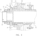
FIG. 3 is a cross sectional view showing the application of a part of the heat dissipation structure of the power wheel axle shaft according to the first embodiment of the present invention. -
FIG. 4 is a cross sectional view showing the assembly of a part of the heat dissipation structure of the power wheel axle shaft according to a second embodiment of the present invention. -
FIG. 5 is a perspective view showing the assembly of a part of the heat dissipation structure of a power wheel axle shaft according to a third embodiment of the present invention. - With reference to
FIGS. 1 and2 , a heat dissipation structure of a power wheel axle shaft of an electronic motorcycle according to a first embodiment of the present invention comprises ashaft body 10 and athermal conduction element 20. Theshaft body 10 is a hollow tube, a first end of theshaft body 10 is in connection with a frame unit (not shown) of the electronic motorcycle, wherein theshaft body 10 is coupled with a rocker arm of the frame unit based on using requirements, and thethermal conduction element 20 is fitted with a second end of theshaft body 10. The frame unit and the rocker arm are well-known arts, so further remarks are omitted. - The
thermal conduction element 20 is tubular and is made of thermal conductive metal, for example, thethermal conduction element 20 is made of copper or copper alloy. Thethermal conduction element 20 includes a firsttubular section 22 and a secondtubular section 24 connecting with the firsttubular section 22 by using aconnection portion 26, wherein an inner diameter of the firsttubular section 22 is less than the secondtubular section 24. Theshaft body 10 is connected with the firsttubular section 22 via the secondtubular section 24, the firsttubular section 22 has twoplanes 222 formed on an outer wall thereof, each of the twoplanes 222 is symmetrical to a center of the firsttubular section 22, and the secondtubular section 24 has a threadedportion 242 formed on an inner wall thereof. - Referring to
FIG. 3 , theshaft body 10 is connected with a stator of a hub motor, and the hub motor is applied to drive the power wheel of the electronic wheel. The stator includes asupport rack 32 and multiple coil sets (not shown), wherein each of the multiple coil sets is arranged around an outer wall of thesupport rack 32, and thesupport rack 32 has abushing 322 formed on a central axle thereof and configured to accommodate theshaft body 10, whereinmultiple keys 36 are defined between theshaft body 10 and thebushing 322 so that theshaft body 10 is coupled with thesupport rack 32. The secondtubular section 24 is fitted into thebushing 322 so as to be screwed with thebushing 322 by way of the threadedsection 242. The twoplanes 222 are clamped by a wrench or other hand tools, hence thethermal conduction element 20 is rotated to connect with or remove from thesupport rack 32. - The
thermal conduction element 20 is rotatably connected with a casing (not shown) of the hub motor so that the stator and theshaft body 10 dissipate heat out of the hub motor via thethermal conduction element 20. Thethermal conduction element 20 is connected with abearing 40 and a dust-proof cover 50 so that thethermal conduction element 20 is rotatably connected with the casing (not shown) of the hub motor, and an interior of theshaft body 10 communicates with an exterior outside the hub motor via the firsttubular section 22, and thethermal conduction section 20 is connected with thebearing 40 and the dust-proof cover 50 via the firsttubular section 22. - As shown in
FIG. 4 , a difference of a heat dissipation structure of a second embodiment from that of the first embodiment comprises: ashaft body 10 and athermal conduction element 20, wherein thethermal conduction element 20 is fitted with afitting sleeve 60 which is fitted on an outer wall of the firsttubular section 22, and thefitting sleeve 60 includes aperipheral rib 62 extending outward from an outer wall thereof and configured to abut against theconnection portion 26 of thethermal conduction element 20, such that thefitting sleeve 60 is defined among thethermal conduction element 20, thebearing 40, and the dust-proof cover 50 so as to reduce heat of thebearing 40 and the dust-proof cover 50 from thethermal conduction element 20. - As illustrated in
FIG. 5 , a difference of a heat dissipation structure of a third embodiment from that of the first embodiment comprises: thethermal conduction element 20 including apolygonal engagement portion 28 formed on an outer wall of thethermal conduction element 20 and clamped by a wrench or other hand tools, hence thethermal conduction element 20 is rotated by the wrench or other hand tools easily. Furthermore, theengagement portion 28 is formed on an outer wall of the secondtubular section 24. - Accordingly, the heat is conducted to the
support rack 32 and theshaft body 10 from multiple coil sets, so a temperature of thesupport rack 32 and theshaft body 10 enhances. Thereafter, thesupport rack 32 and theshaft body 10 conducts the heat to thethermal conduction element 20 so that the heat is dissipated to the exterior outside the hub motor through thethermal conduction element 20, thus reducing the heat to theshaft body 10 from thesupport rack 32 and enhancing heat dissipation of theshaft body 10.
Claims (5)
- A power wheel axle shaft of an electric motorcycle having a heat dissipation structure comprising a shaft body (10) and a thermal conduction element (20), wherein the shaft body (10) is a hollow tube, a first end of the shaft body (10) is in connection with a frame unit of the electric motorcycle, the thermal conduction element (20) is fitted on a second end of the shaft body (10), and the shaft body (10) is connected to a support rack (32) of a stator of a hub motor, characterized in that the support rack (32) has a bushing (322) formed on a central axis thereof and which accommodates the shaft body (10);
the thermal conduction element (20) is tubular and is made of thermal conductive metal, the thermal conduction element (20) includes a first tubular section (22) and a second tubular section (24) connecting with the first tubular section (22) by using a connection portion (26), wherein the shaft body (10) is connected with the thermal conduction element (20) via the first tubular section (22), and the second tubular section (24) is fitted onto the bushing (322). - The power wheel axle shaft as claimed in claim 1, characterized in that the second tubular section (24) has a threaded portion (242) formed on an inner wall thereof so that the second tubular section (24) screws with the bushing (322).
- The power wheel axle shaft as claimed in claim 2, characterized in that the first tubular section (22) has two planes (222) formed on an outer wall thereof, each of the two planes (222) is symmetrical relative to the center of the first tubular section (22) so that it can be clamped by a wrench or other hand tools, hence the thermal conduction element (20) is rotated to connect with or remove from the support rack (32).
- The power wheel axle shaft as claimed in claim 1, characterized in that the thermal conduction element (20) is provided with a fitting sleeve (60) which is fitted on an outer wall of the first tubular section (22).
- The power wheel axle shaft as claimed in claim 4, characterized in that the fitting sleeve (60) includes a peripheral rib (62) extending outward from the outer wall thereof and configured to abut against the connection portion (26) of the thermal conduction element (20).
Applications Claiming Priority (1)
| Application Number | Priority Date | Filing Date | Title |
|---|---|---|---|
| TW106146370A TWI647143B (en) | 2017-12-28 | 2017-12-28 | Heat radiation structure of power wheel axle of electric locomotive |
Publications (2)
| Publication Number | Publication Date |
|---|---|
| EP3505435A1 EP3505435A1 (en) | 2019-07-03 |
| EP3505435B1 true EP3505435B1 (en) | 2020-09-09 |
Family
ID=63762232
Family Applications (1)
| Application Number | Title | Priority Date | Filing Date |
|---|---|---|---|
| EP18197929.5A Active EP3505435B1 (en) | 2017-12-28 | 2018-10-01 | Heat dissipation structure of axle shaft for power wheel of electric motorcycle |
Country Status (2)
| Country | Link |
|---|---|
| EP (1) | EP3505435B1 (en) |
| TW (1) | TWI647143B (en) |
Families Citing this family (1)
| Publication number | Priority date | Publication date | Assignee | Title |
|---|---|---|---|---|
| CN114655349A (en) * | 2020-12-23 | 2022-06-24 | 宁波联拓思维电子科技有限公司 | Electric scooter wheel and electric scooter with motor |
Family Cites Families (9)
| Publication number | Priority date | Publication date | Assignee | Title |
|---|---|---|---|---|
| US4409789A (en) * | 1980-11-03 | 1983-10-18 | Clark Equipment Company | Power steering system |
| DE19732273A1 (en) * | 1997-07-26 | 1999-07-22 | Dietrich Gerhard Ellsaesser | Direct drive unit for wheel hub drive |
| CN101877524B (en) * | 2009-04-30 | 2013-03-20 | 浙江中科德润科技有限公司 | Integrated hub motor |
| FR2949028B1 (en) * | 2009-08-04 | 2014-06-27 | Daniel Giudice | MOTOR ELECTRIC WHEEL ADAPTED TO A ROLLING VEHICLE DIMMER. |
| JP4932012B2 (en) * | 2010-01-29 | 2012-05-16 | 日本電産コパル株式会社 | Electric hub unit |
| TWI424663B (en) * | 2010-07-01 | 2014-01-21 | Joy Ride Tech Co Ltd | A motor with heat pipe |
| CN103296812B (en) * | 2012-03-05 | 2017-02-08 | 德昌电机(深圳)有限公司 | Motor stator and motor with stator |
| TWI572125B (en) * | 2015-09-23 | 2017-02-21 | Rotor heat dissipation structure of inner rotor motor | |
| US9598141B1 (en) * | 2016-03-07 | 2017-03-21 | Future Motion, Inc. | Thermally enhanced hub motor |
-
2017
- 2017-12-28 TW TW106146370A patent/TWI647143B/en not_active IP Right Cessation
-
2018
- 2018-10-01 EP EP18197929.5A patent/EP3505435B1/en active Active
Non-Patent Citations (1)
| Title |
|---|
| None * |
Also Published As
| Publication number | Publication date |
|---|---|
| EP3505435A1 (en) | 2019-07-03 |
| TW201930135A (en) | 2019-08-01 |
| TWI647143B (en) | 2019-01-11 |
Similar Documents
| Publication | Publication Date | Title |
|---|---|---|
| CN112534682B (en) | Sealed axial flux motor with integrated cooling | |
| JP2017519680A (en) | Stator assembly for electric motor wheels and stub axle support structure therefor | |
| EP3175145B1 (en) | Linear actuator | |
| CN110890803B (en) | External type rotating electrical machines and traction machines | |
| US20060276122A1 (en) | Electric fan | |
| US20110247450A1 (en) | Bicycle Pedal | |
| KR20200042813A (en) | Hollow Shaft Motor | |
| EP3505435A1 (en) | Heat dissipation structure of axle shaft for power wheel of electric motorcycle | |
| KR100987882B1 (en) | Handpiece with cooling means | |
| US10677443B2 (en) | Lamp with internally mounted heat dissipation device | |
| US20080273826A1 (en) | Wheel axle dismounting device | |
| US9543811B2 (en) | Heatsink design with thermal insulator to reduce encoder temperature | |
| TWI847710B (en) | Hub motor | |
| US7157825B1 (en) | Motor | |
| US20120161589A1 (en) | Bicycle generator hub stator and bicycle generator hub | |
| JP6098872B2 (en) | In-wheel motor | |
| US9812924B2 (en) | Motor assembly for an electric power steering assembly | |
| EP3730393B1 (en) | Single-wheeled balancing vehicle | |
| JP5350738B2 (en) | Tool socket | |
| JP2016135622A (en) | Vehicle door mirror | |
| US10135321B2 (en) | Heatsink design with thermal insulator to reduce encoder temperature | |
| TW202448080A (en) | Hub motor | |
| CN216699739U (en) | Brushless DC motor heat radiation structure of high IP level | |
| CN222321254U (en) | A permanent magnet brushless DC spindle motor | |
| CN218633524U (en) | Brushless DC motor |
Legal Events
| Date | Code | Title | Description |
|---|---|---|---|
| PUAI | Public reference made under article 153(3) epc to a published international application that has entered the european phase |
Free format text: ORIGINAL CODE: 0009012 |
|
| STAA | Information on the status of an ep patent application or granted ep patent |
Free format text: STATUS: THE APPLICATION HAS BEEN PUBLISHED |
|
| AK | Designated contracting states |
Kind code of ref document: A1 Designated state(s): AL AT BE BG CH CY CZ DE DK EE ES FI FR GB GR HR HU IE IS IT LI LT LU LV MC MK MT NL NO PL PT RO RS SE SI SK SM TR |
|
| AX | Request for extension of the european patent |
Extension state: BA ME |
|
| STAA | Information on the status of an ep patent application or granted ep patent |
Free format text: STATUS: REQUEST FOR EXAMINATION WAS MADE |
|
| 17P | Request for examination filed |
Effective date: 20191210 |
|
| RBV | Designated contracting states (corrected) |
Designated state(s): AL AT BE BG CH CY CZ DE DK EE ES FI FR GB GR HR HU IE IS IT LI LT LU LV MC MK MT NL NO PL PT RO RS SE SI SK SM TR |
|
| GRAP | Despatch of communication of intention to grant a patent |
Free format text: ORIGINAL CODE: EPIDOSNIGR1 |
|
| STAA | Information on the status of an ep patent application or granted ep patent |
Free format text: STATUS: GRANT OF PATENT IS INTENDED |
|
| RIC1 | Information provided on ipc code assigned before grant |
Ipc: B62K 25/00 20060101ALN20200226BHEP Ipc: B60K 7/00 20060101ALI20200226BHEP Ipc: B62M 23/02 20100101ALI20200226BHEP Ipc: B62M 7/12 20060101ALI20200226BHEP Ipc: B62K 25/02 20060101ALI20200226BHEP Ipc: B62K 25/28 20060101AFI20200226BHEP |
|
| RIC1 | Information provided on ipc code assigned before grant |
Ipc: B62K 25/28 20060101AFI20200303BHEP Ipc: B62M 23/02 20100101ALI20200303BHEP Ipc: B62K 25/02 20060101ALI20200303BHEP Ipc: B62K 25/00 20060101ALN20200303BHEP Ipc: B62M 7/12 20060101ALI20200303BHEP Ipc: B60K 7/00 20060101ALI20200303BHEP |
|
| RIC1 | Information provided on ipc code assigned before grant |
Ipc: B62K 25/00 20060101ALN20200310BHEP Ipc: B62M 23/02 20100101ALI20200310BHEP Ipc: B62K 25/02 20060101ALI20200310BHEP Ipc: B62K 25/28 20060101AFI20200310BHEP Ipc: B62M 7/12 20060101ALI20200310BHEP Ipc: B60K 7/00 20060101ALI20200310BHEP |
|
| INTG | Intention to grant announced |
Effective date: 20200325 |
|
| GRAS | Grant fee paid |
Free format text: ORIGINAL CODE: EPIDOSNIGR3 |
|
| GRAA | (expected) grant |
Free format text: ORIGINAL CODE: 0009210 |
|
| STAA | Information on the status of an ep patent application or granted ep patent |
Free format text: STATUS: THE PATENT HAS BEEN GRANTED |
|
| AK | Designated contracting states |
Kind code of ref document: B1 Designated state(s): AL AT BE BG CH CY CZ DE DK EE ES FI FR GB GR HR HU IE IS IT LI LT LU LV MC MK MT NL NO PL PT RO RS SE SI SK SM TR |
|
| REG | Reference to a national code |
Ref country code: GB Ref legal event code: FG4D |
|
| REG | Reference to a national code |
Ref country code: AT Ref legal event code: REF Ref document number: 1311259 Country of ref document: AT Kind code of ref document: T Effective date: 20200915 Ref country code: CH Ref legal event code: EP |
|
| REG | Reference to a national code |
Ref country code: DE Ref legal event code: R096 Ref document number: 602018007585 Country of ref document: DE |
|
| REG | Reference to a national code |
Ref country code: IE Ref legal event code: FG4D |
|
| REG | Reference to a national code |
Ref country code: LT Ref legal event code: MG4D |
|
| PG25 | Lapsed in a contracting state [announced via postgrant information from national office to epo] |
Ref country code: HR Free format text: LAPSE BECAUSE OF FAILURE TO SUBMIT A TRANSLATION OF THE DESCRIPTION OR TO PAY THE FEE WITHIN THE PRESCRIBED TIME-LIMIT Effective date: 20200909 Ref country code: GR Free format text: LAPSE BECAUSE OF FAILURE TO SUBMIT A TRANSLATION OF THE DESCRIPTION OR TO PAY THE FEE WITHIN THE PRESCRIBED TIME-LIMIT Effective date: 20201210 Ref country code: LT Free format text: LAPSE BECAUSE OF FAILURE TO SUBMIT A TRANSLATION OF THE DESCRIPTION OR TO PAY THE FEE WITHIN THE PRESCRIBED TIME-LIMIT Effective date: 20200909 Ref country code: FI Free format text: LAPSE BECAUSE OF FAILURE TO SUBMIT A TRANSLATION OF THE DESCRIPTION OR TO PAY THE FEE WITHIN THE PRESCRIBED TIME-LIMIT Effective date: 20200909 Ref country code: SE Free format text: LAPSE BECAUSE OF FAILURE TO SUBMIT A TRANSLATION OF THE DESCRIPTION OR TO PAY THE FEE WITHIN THE PRESCRIBED TIME-LIMIT Effective date: 20200909 Ref country code: NO Free format text: LAPSE BECAUSE OF FAILURE TO SUBMIT A TRANSLATION OF THE DESCRIPTION OR TO PAY THE FEE WITHIN THE PRESCRIBED TIME-LIMIT Effective date: 20201209 Ref country code: BG Free format text: LAPSE BECAUSE OF FAILURE TO SUBMIT A TRANSLATION OF THE DESCRIPTION OR TO PAY THE FEE WITHIN THE PRESCRIBED TIME-LIMIT Effective date: 20201209 |
|
| REG | Reference to a national code |
Ref country code: AT Ref legal event code: MK05 Ref document number: 1311259 Country of ref document: AT Kind code of ref document: T Effective date: 20200909 |
|
| REG | Reference to a national code |
Ref country code: NL Ref legal event code: MP Effective date: 20200909 |
|
| PG25 | Lapsed in a contracting state [announced via postgrant information from national office to epo] |
Ref country code: RS Free format text: LAPSE BECAUSE OF FAILURE TO SUBMIT A TRANSLATION OF THE DESCRIPTION OR TO PAY THE FEE WITHIN THE PRESCRIBED TIME-LIMIT Effective date: 20200909 Ref country code: PL Free format text: LAPSE BECAUSE OF FAILURE TO SUBMIT A TRANSLATION OF THE DESCRIPTION OR TO PAY THE FEE WITHIN THE PRESCRIBED TIME-LIMIT Effective date: 20200909 Ref country code: LV Free format text: LAPSE BECAUSE OF FAILURE TO SUBMIT A TRANSLATION OF THE DESCRIPTION OR TO PAY THE FEE WITHIN THE PRESCRIBED TIME-LIMIT Effective date: 20200909 |
|
| PG25 | Lapsed in a contracting state [announced via postgrant information from national office to epo] |
Ref country code: EE Free format text: LAPSE BECAUSE OF FAILURE TO SUBMIT A TRANSLATION OF THE DESCRIPTION OR TO PAY THE FEE WITHIN THE PRESCRIBED TIME-LIMIT Effective date: 20200909 Ref country code: CZ Free format text: LAPSE BECAUSE OF FAILURE TO SUBMIT A TRANSLATION OF THE DESCRIPTION OR TO PAY THE FEE WITHIN THE PRESCRIBED TIME-LIMIT Effective date: 20200909 Ref country code: PT Free format text: LAPSE BECAUSE OF FAILURE TO SUBMIT A TRANSLATION OF THE DESCRIPTION OR TO PAY THE FEE WITHIN THE PRESCRIBED TIME-LIMIT Effective date: 20210111 Ref country code: RO Free format text: LAPSE BECAUSE OF FAILURE TO SUBMIT A TRANSLATION OF THE DESCRIPTION OR TO PAY THE FEE WITHIN THE PRESCRIBED TIME-LIMIT Effective date: 20200909 Ref country code: SM Free format text: LAPSE BECAUSE OF FAILURE TO SUBMIT A TRANSLATION OF THE DESCRIPTION OR TO PAY THE FEE WITHIN THE PRESCRIBED TIME-LIMIT Effective date: 20200909 |
|
| PG25 | Lapsed in a contracting state [announced via postgrant information from national office to epo] |
Ref country code: AL Free format text: LAPSE BECAUSE OF FAILURE TO SUBMIT A TRANSLATION OF THE DESCRIPTION OR TO PAY THE FEE WITHIN THE PRESCRIBED TIME-LIMIT Effective date: 20200909 Ref country code: AT Free format text: LAPSE BECAUSE OF FAILURE TO SUBMIT A TRANSLATION OF THE DESCRIPTION OR TO PAY THE FEE WITHIN THE PRESCRIBED TIME-LIMIT Effective date: 20200909 Ref country code: ES Free format text: LAPSE BECAUSE OF FAILURE TO SUBMIT A TRANSLATION OF THE DESCRIPTION OR TO PAY THE FEE WITHIN THE PRESCRIBED TIME-LIMIT Effective date: 20200909 Ref country code: IS Free format text: LAPSE BECAUSE OF FAILURE TO SUBMIT A TRANSLATION OF THE DESCRIPTION OR TO PAY THE FEE WITHIN THE PRESCRIBED TIME-LIMIT Effective date: 20210109 |
|
| REG | Reference to a national code |
Ref country code: DE Ref legal event code: R097 Ref document number: 602018007585 Country of ref document: DE |
|
| PG25 | Lapsed in a contracting state [announced via postgrant information from national office to epo] |
Ref country code: MC Free format text: LAPSE BECAUSE OF FAILURE TO SUBMIT A TRANSLATION OF THE DESCRIPTION OR TO PAY THE FEE WITHIN THE PRESCRIBED TIME-LIMIT Effective date: 20200909 Ref country code: LU Free format text: LAPSE BECAUSE OF NON-PAYMENT OF DUE FEES Effective date: 20201001 Ref country code: SK Free format text: LAPSE BECAUSE OF FAILURE TO SUBMIT A TRANSLATION OF THE DESCRIPTION OR TO PAY THE FEE WITHIN THE PRESCRIBED TIME-LIMIT Effective date: 20200909 |
|
| REG | Reference to a national code |
Ref country code: BE Ref legal event code: MM Effective date: 20201031 |
|
| PLBE | No opposition filed within time limit |
Free format text: ORIGINAL CODE: 0009261 |
|
| STAA | Information on the status of an ep patent application or granted ep patent |
Free format text: STATUS: NO OPPOSITION FILED WITHIN TIME LIMIT |
|
| 26N | No opposition filed |
Effective date: 20210610 |
|
| PG25 | Lapsed in a contracting state [announced via postgrant information from national office to epo] |
Ref country code: DK Free format text: LAPSE BECAUSE OF FAILURE TO SUBMIT A TRANSLATION OF THE DESCRIPTION OR TO PAY THE FEE WITHIN THE PRESCRIBED TIME-LIMIT Effective date: 20200909 Ref country code: SI Free format text: LAPSE BECAUSE OF FAILURE TO SUBMIT A TRANSLATION OF THE DESCRIPTION OR TO PAY THE FEE WITHIN THE PRESCRIBED TIME-LIMIT Effective date: 20200909 Ref country code: BE Free format text: LAPSE BECAUSE OF NON-PAYMENT OF DUE FEES Effective date: 20201031 |
|
| PG25 | Lapsed in a contracting state [announced via postgrant information from national office to epo] |
Ref country code: IE Free format text: LAPSE BECAUSE OF NON-PAYMENT OF DUE FEES Effective date: 20201001 |
|
| REG | Reference to a national code |
Ref country code: CH Ref legal event code: PL |
|
| PG25 | Lapsed in a contracting state [announced via postgrant information from national office to epo] |
Ref country code: TR Free format text: LAPSE BECAUSE OF FAILURE TO SUBMIT A TRANSLATION OF THE DESCRIPTION OR TO PAY THE FEE WITHIN THE PRESCRIBED TIME-LIMIT Effective date: 20200909 Ref country code: MT Free format text: LAPSE BECAUSE OF FAILURE TO SUBMIT A TRANSLATION OF THE DESCRIPTION OR TO PAY THE FEE WITHIN THE PRESCRIBED TIME-LIMIT Effective date: 20200909 Ref country code: CY Free format text: LAPSE BECAUSE OF FAILURE TO SUBMIT A TRANSLATION OF THE DESCRIPTION OR TO PAY THE FEE WITHIN THE PRESCRIBED TIME-LIMIT Effective date: 20200909 |
|
| PG25 | Lapsed in a contracting state [announced via postgrant information from national office to epo] |
Ref country code: MK Free format text: LAPSE BECAUSE OF FAILURE TO SUBMIT A TRANSLATION OF THE DESCRIPTION OR TO PAY THE FEE WITHIN THE PRESCRIBED TIME-LIMIT Effective date: 20200909 |
|
| PG25 | Lapsed in a contracting state [announced via postgrant information from national office to epo] |
Ref country code: LI Free format text: LAPSE BECAUSE OF NON-PAYMENT OF DUE FEES Effective date: 20211031 Ref country code: CH Free format text: LAPSE BECAUSE OF NON-PAYMENT OF DUE FEES Effective date: 20211031 |
|
| PGFP | Annual fee paid to national office [announced via postgrant information from national office to epo] |
Ref country code: GB Payment date: 20220921 Year of fee payment: 5 |
|
| PGFP | Annual fee paid to national office [announced via postgrant information from national office to epo] |
Ref country code: FR Payment date: 20221020 Year of fee payment: 5 |
|
| PGFP | Annual fee paid to national office [announced via postgrant information from national office to epo] |
Ref country code: IT Payment date: 20221004 Year of fee payment: 5 Ref country code: DE Payment date: 20221020 Year of fee payment: 5 |
|
| PG25 | Lapsed in a contracting state [announced via postgrant information from national office to epo] |
Ref country code: NL Free format text: LAPSE BECAUSE OF NON-PAYMENT OF DUE FEES Effective date: 20200923 |
|
| REG | Reference to a national code |
Ref country code: DE Ref legal event code: R119 Ref document number: 602018007585 Country of ref document: DE |
|
| GBPC | Gb: european patent ceased through non-payment of renewal fee |
Effective date: 20231001 |
|
| PG25 | Lapsed in a contracting state [announced via postgrant information from national office to epo] |
Ref country code: GB Free format text: LAPSE BECAUSE OF NON-PAYMENT OF DUE FEES Effective date: 20231001 |
|
| PG25 | Lapsed in a contracting state [announced via postgrant information from national office to epo] |
Ref country code: GB Free format text: LAPSE BECAUSE OF NON-PAYMENT OF DUE FEES Effective date: 20231001 Ref country code: FR Free format text: LAPSE BECAUSE OF NON-PAYMENT OF DUE FEES Effective date: 20231031 Ref country code: DE Free format text: LAPSE BECAUSE OF NON-PAYMENT OF DUE FEES Effective date: 20240501 |
|
| PG25 | Lapsed in a contracting state [announced via postgrant information from national office to epo] |
Ref country code: IT Free format text: LAPSE BECAUSE OF NON-PAYMENT OF DUE FEES Effective date: 20231001 |
|
| PG25 | Lapsed in a contracting state [announced via postgrant information from national office to epo] |
Ref country code: IT Free format text: LAPSE BECAUSE OF NON-PAYMENT OF DUE FEES Effective date: 20231001 |