EP3505411A1 - Power source for electric vehicle and power source selection method - Google Patents
Power source for electric vehicle and power source selection method Download PDFInfo
- Publication number
- EP3505411A1 EP3505411A1 EP17860562.2A EP17860562A EP3505411A1 EP 3505411 A1 EP3505411 A1 EP 3505411A1 EP 17860562 A EP17860562 A EP 17860562A EP 3505411 A1 EP3505411 A1 EP 3505411A1
- Authority
- EP
- European Patent Office
- Prior art keywords
- value
- power battery
- driving mode
- power
- battery
- Prior art date
- Legal status (The legal status is an assumption and is not a legal conclusion. Google has not performed a legal analysis and makes no representation as to the accuracy of the status listed.)
- Granted
Links
- 238000010187 selection method Methods 0.000 title claims abstract description 4
- 208000032953 Device battery issue Diseases 0.000 claims description 2
- 238000000034 method Methods 0.000 abstract description 17
- 239000000446 fuel Substances 0.000 abstract description 6
- 230000001133 acceleration Effects 0.000 description 21
- 238000010586 diagram Methods 0.000 description 14
- 230000009194 climbing Effects 0.000 description 7
- 238000011217 control strategy Methods 0.000 description 7
- 238000007599 discharging Methods 0.000 description 3
- 238000012986 modification Methods 0.000 description 2
- 230000004048 modification Effects 0.000 description 2
- 238000002485 combustion reaction Methods 0.000 description 1
- 238000010248 power generation Methods 0.000 description 1
Images


Classifications
-
- B—PERFORMING OPERATIONS; TRANSPORTING
- B60—VEHICLES IN GENERAL
- B60W—CONJOINT CONTROL OF VEHICLE SUB-UNITS OF DIFFERENT TYPE OR DIFFERENT FUNCTION; CONTROL SYSTEMS SPECIALLY ADAPTED FOR HYBRID VEHICLES; ROAD VEHICLE DRIVE CONTROL SYSTEMS FOR PURPOSES NOT RELATED TO THE CONTROL OF A PARTICULAR SUB-UNIT
- B60W10/00—Conjoint control of vehicle sub-units of different type or different function
- B60W10/04—Conjoint control of vehicle sub-units of different type or different function including control of propulsion units
- B60W10/06—Conjoint control of vehicle sub-units of different type or different function including control of propulsion units including control of combustion engines
-
- B—PERFORMING OPERATIONS; TRANSPORTING
- B60—VEHICLES IN GENERAL
- B60L—PROPULSION OF ELECTRICALLY-PROPELLED VEHICLES; SUPPLYING ELECTRIC POWER FOR AUXILIARY EQUIPMENT OF ELECTRICALLY-PROPELLED VEHICLES; ELECTRODYNAMIC BRAKE SYSTEMS FOR VEHICLES IN GENERAL; MAGNETIC SUSPENSION OR LEVITATION FOR VEHICLES; MONITORING OPERATING VARIABLES OF ELECTRICALLY-PROPELLED VEHICLES; ELECTRIC SAFETY DEVICES FOR ELECTRICALLY-PROPELLED VEHICLES
- B60L50/00—Electric propulsion with power supplied within the vehicle
- B60L50/50—Electric propulsion with power supplied within the vehicle using propulsion power supplied by batteries or fuel cells
- B60L50/60—Electric propulsion with power supplied within the vehicle using propulsion power supplied by batteries or fuel cells using power supplied by batteries
- B60L50/61—Electric propulsion with power supplied within the vehicle using propulsion power supplied by batteries or fuel cells using power supplied by batteries by batteries charged by engine-driven generators, e.g. series hybrid electric vehicles
-
- B—PERFORMING OPERATIONS; TRANSPORTING
- B60—VEHICLES IN GENERAL
- B60K—ARRANGEMENT OR MOUNTING OF PROPULSION UNITS OR OF TRANSMISSIONS IN VEHICLES; ARRANGEMENT OR MOUNTING OF PLURAL DIVERSE PRIME-MOVERS IN VEHICLES; AUXILIARY DRIVES FOR VEHICLES; INSTRUMENTATION OR DASHBOARDS FOR VEHICLES; ARRANGEMENTS IN CONNECTION WITH COOLING, AIR INTAKE, GAS EXHAUST OR FUEL SUPPLY OF PROPULSION UNITS IN VEHICLES
- B60K6/00—Arrangement or mounting of plural diverse prime-movers for mutual or common propulsion, e.g. hybrid propulsion systems comprising electric motors and internal combustion engines ; Control systems therefor, i.e. systems controlling two or more prime movers, or controlling one of these prime movers and any of the transmission, drive or drive units Informative references: mechanical gearings with secondary electric drive F16H3/72; arrangements for handling mechanical energy structurally associated with the dynamo-electric machine H02K7/00; machines comprising structurally interrelated motor and generator parts H02K51/00; dynamo-electric machines not otherwise provided for in H02K see H02K99/00
- B60K6/20—Arrangement or mounting of plural diverse prime-movers for mutual or common propulsion, e.g. hybrid propulsion systems comprising electric motors and internal combustion engines ; Control systems therefor, i.e. systems controlling two or more prime movers, or controlling one of these prime movers and any of the transmission, drive or drive units Informative references: mechanical gearings with secondary electric drive F16H3/72; arrangements for handling mechanical energy structurally associated with the dynamo-electric machine H02K7/00; machines comprising structurally interrelated motor and generator parts H02K51/00; dynamo-electric machines not otherwise provided for in H02K see H02K99/00 the prime-movers consisting of electric motors and internal combustion engines, e.g. HEVs
- B60K6/42—Arrangement or mounting of plural diverse prime-movers for mutual or common propulsion, e.g. hybrid propulsion systems comprising electric motors and internal combustion engines ; Control systems therefor, i.e. systems controlling two or more prime movers, or controlling one of these prime movers and any of the transmission, drive or drive units Informative references: mechanical gearings with secondary electric drive F16H3/72; arrangements for handling mechanical energy structurally associated with the dynamo-electric machine H02K7/00; machines comprising structurally interrelated motor and generator parts H02K51/00; dynamo-electric machines not otherwise provided for in H02K see H02K99/00 the prime-movers consisting of electric motors and internal combustion engines, e.g. HEVs characterised by the architecture of the hybrid electric vehicle
- B60K6/46—Series type
-
- B—PERFORMING OPERATIONS; TRANSPORTING
- B60—VEHICLES IN GENERAL
- B60L—PROPULSION OF ELECTRICALLY-PROPELLED VEHICLES; SUPPLYING ELECTRIC POWER FOR AUXILIARY EQUIPMENT OF ELECTRICALLY-PROPELLED VEHICLES; ELECTRODYNAMIC BRAKE SYSTEMS FOR VEHICLES IN GENERAL; MAGNETIC SUSPENSION OR LEVITATION FOR VEHICLES; MONITORING OPERATING VARIABLES OF ELECTRICALLY-PROPELLED VEHICLES; ELECTRIC SAFETY DEVICES FOR ELECTRICALLY-PROPELLED VEHICLES
- B60L3/00—Electric devices on electrically-propelled vehicles for safety purposes; Monitoring operating variables, e.g. speed, deceleration or energy consumption
- B60L3/0023—Detecting, eliminating, remedying or compensating for drive train abnormalities, e.g. failures within the drive train
-
- B—PERFORMING OPERATIONS; TRANSPORTING
- B60—VEHICLES IN GENERAL
- B60L—PROPULSION OF ELECTRICALLY-PROPELLED VEHICLES; SUPPLYING ELECTRIC POWER FOR AUXILIARY EQUIPMENT OF ELECTRICALLY-PROPELLED VEHICLES; ELECTRODYNAMIC BRAKE SYSTEMS FOR VEHICLES IN GENERAL; MAGNETIC SUSPENSION OR LEVITATION FOR VEHICLES; MONITORING OPERATING VARIABLES OF ELECTRICALLY-PROPELLED VEHICLES; ELECTRIC SAFETY DEVICES FOR ELECTRICALLY-PROPELLED VEHICLES
- B60L58/00—Methods or circuit arrangements for monitoring or controlling batteries or fuel cells, specially adapted for electric vehicles
- B60L58/10—Methods or circuit arrangements for monitoring or controlling batteries or fuel cells, specially adapted for electric vehicles for monitoring or controlling batteries
- B60L58/12—Methods or circuit arrangements for monitoring or controlling batteries or fuel cells, specially adapted for electric vehicles for monitoring or controlling batteries responding to state of charge [SoC]
- B60L58/13—Maintaining the SoC within a determined range
-
- B—PERFORMING OPERATIONS; TRANSPORTING
- B60—VEHICLES IN GENERAL
- B60W—CONJOINT CONTROL OF VEHICLE SUB-UNITS OF DIFFERENT TYPE OR DIFFERENT FUNCTION; CONTROL SYSTEMS SPECIALLY ADAPTED FOR HYBRID VEHICLES; ROAD VEHICLE DRIVE CONTROL SYSTEMS FOR PURPOSES NOT RELATED TO THE CONTROL OF A PARTICULAR SUB-UNIT
- B60W10/00—Conjoint control of vehicle sub-units of different type or different function
- B60W10/04—Conjoint control of vehicle sub-units of different type or different function including control of propulsion units
- B60W10/08—Conjoint control of vehicle sub-units of different type or different function including control of propulsion units including control of electric propulsion units, e.g. motors or generators
-
- B—PERFORMING OPERATIONS; TRANSPORTING
- B60—VEHICLES IN GENERAL
- B60W—CONJOINT CONTROL OF VEHICLE SUB-UNITS OF DIFFERENT TYPE OR DIFFERENT FUNCTION; CONTROL SYSTEMS SPECIALLY ADAPTED FOR HYBRID VEHICLES; ROAD VEHICLE DRIVE CONTROL SYSTEMS FOR PURPOSES NOT RELATED TO THE CONTROL OF A PARTICULAR SUB-UNIT
- B60W10/00—Conjoint control of vehicle sub-units of different type or different function
- B60W10/24—Conjoint control of vehicle sub-units of different type or different function including control of energy storage means
- B60W10/26—Conjoint control of vehicle sub-units of different type or different function including control of energy storage means for electrical energy, e.g. batteries or capacitors
-
- B—PERFORMING OPERATIONS; TRANSPORTING
- B60—VEHICLES IN GENERAL
- B60W—CONJOINT CONTROL OF VEHICLE SUB-UNITS OF DIFFERENT TYPE OR DIFFERENT FUNCTION; CONTROL SYSTEMS SPECIALLY ADAPTED FOR HYBRID VEHICLES; ROAD VEHICLE DRIVE CONTROL SYSTEMS FOR PURPOSES NOT RELATED TO THE CONTROL OF A PARTICULAR SUB-UNIT
- B60W20/00—Control systems specially adapted for hybrid vehicles
- B60W20/10—Controlling the power contribution of each of the prime movers to meet required power demand
- B60W20/13—Controlling the power contribution of each of the prime movers to meet required power demand in order to stay within battery power input or output limits; in order to prevent overcharging or battery depletion
-
- B—PERFORMING OPERATIONS; TRANSPORTING
- B60—VEHICLES IN GENERAL
- B60W—CONJOINT CONTROL OF VEHICLE SUB-UNITS OF DIFFERENT TYPE OR DIFFERENT FUNCTION; CONTROL SYSTEMS SPECIALLY ADAPTED FOR HYBRID VEHICLES; ROAD VEHICLE DRIVE CONTROL SYSTEMS FOR PURPOSES NOT RELATED TO THE CONTROL OF A PARTICULAR SUB-UNIT
- B60W20/00—Control systems specially adapted for hybrid vehicles
- B60W20/50—Control strategies for responding to system failures, e.g. for fault diagnosis, failsafe operation or limp mode
-
- B—PERFORMING OPERATIONS; TRANSPORTING
- B60—VEHICLES IN GENERAL
- B60W—CONJOINT CONTROL OF VEHICLE SUB-UNITS OF DIFFERENT TYPE OR DIFFERENT FUNCTION; CONTROL SYSTEMS SPECIALLY ADAPTED FOR HYBRID VEHICLES; ROAD VEHICLE DRIVE CONTROL SYSTEMS FOR PURPOSES NOT RELATED TO THE CONTROL OF A PARTICULAR SUB-UNIT
- B60W40/00—Estimation or calculation of non-directly measurable driving parameters for road vehicle drive control systems not related to the control of a particular sub unit, e.g. by using mathematical models
-
- B—PERFORMING OPERATIONS; TRANSPORTING
- B60—VEHICLES IN GENERAL
- B60L—PROPULSION OF ELECTRICALLY-PROPELLED VEHICLES; SUPPLYING ELECTRIC POWER FOR AUXILIARY EQUIPMENT OF ELECTRICALLY-PROPELLED VEHICLES; ELECTRODYNAMIC BRAKE SYSTEMS FOR VEHICLES IN GENERAL; MAGNETIC SUSPENSION OR LEVITATION FOR VEHICLES; MONITORING OPERATING VARIABLES OF ELECTRICALLY-PROPELLED VEHICLES; ELECTRIC SAFETY DEVICES FOR ELECTRICALLY-PROPELLED VEHICLES
- B60L2240/00—Control parameters of input or output; Target parameters
- B60L2240/40—Drive Train control parameters
- B60L2240/42—Drive Train control parameters related to electric machines
-
- B—PERFORMING OPERATIONS; TRANSPORTING
- B60—VEHICLES IN GENERAL
- B60L—PROPULSION OF ELECTRICALLY-PROPELLED VEHICLES; SUPPLYING ELECTRIC POWER FOR AUXILIARY EQUIPMENT OF ELECTRICALLY-PROPELLED VEHICLES; ELECTRODYNAMIC BRAKE SYSTEMS FOR VEHICLES IN GENERAL; MAGNETIC SUSPENSION OR LEVITATION FOR VEHICLES; MONITORING OPERATING VARIABLES OF ELECTRICALLY-PROPELLED VEHICLES; ELECTRIC SAFETY DEVICES FOR ELECTRICALLY-PROPELLED VEHICLES
- B60L2240/00—Control parameters of input or output; Target parameters
- B60L2240/40—Drive Train control parameters
- B60L2240/54—Drive Train control parameters related to batteries
-
- B—PERFORMING OPERATIONS; TRANSPORTING
- B60—VEHICLES IN GENERAL
- B60L—PROPULSION OF ELECTRICALLY-PROPELLED VEHICLES; SUPPLYING ELECTRIC POWER FOR AUXILIARY EQUIPMENT OF ELECTRICALLY-PROPELLED VEHICLES; ELECTRODYNAMIC BRAKE SYSTEMS FOR VEHICLES IN GENERAL; MAGNETIC SUSPENSION OR LEVITATION FOR VEHICLES; MONITORING OPERATING VARIABLES OF ELECTRICALLY-PROPELLED VEHICLES; ELECTRIC SAFETY DEVICES FOR ELECTRICALLY-PROPELLED VEHICLES
- B60L2260/00—Operating Modes
- B60L2260/20—Drive modes; Transition between modes
- B60L2260/26—Transition between different drive modes
-
- B—PERFORMING OPERATIONS; TRANSPORTING
- B60—VEHICLES IN GENERAL
- B60L—PROPULSION OF ELECTRICALLY-PROPELLED VEHICLES; SUPPLYING ELECTRIC POWER FOR AUXILIARY EQUIPMENT OF ELECTRICALLY-PROPELLED VEHICLES; ELECTRODYNAMIC BRAKE SYSTEMS FOR VEHICLES IN GENERAL; MAGNETIC SUSPENSION OR LEVITATION FOR VEHICLES; MONITORING OPERATING VARIABLES OF ELECTRICALLY-PROPELLED VEHICLES; ELECTRIC SAFETY DEVICES FOR ELECTRICALLY-PROPELLED VEHICLES
- B60L2260/00—Operating Modes
- B60L2260/40—Control modes
- B60L2260/44—Control modes by parameter estimation
-
- B—PERFORMING OPERATIONS; TRANSPORTING
- B60—VEHICLES IN GENERAL
- B60W—CONJOINT CONTROL OF VEHICLE SUB-UNITS OF DIFFERENT TYPE OR DIFFERENT FUNCTION; CONTROL SYSTEMS SPECIALLY ADAPTED FOR HYBRID VEHICLES; ROAD VEHICLE DRIVE CONTROL SYSTEMS FOR PURPOSES NOT RELATED TO THE CONTROL OF A PARTICULAR SUB-UNIT
- B60W2510/00—Input parameters relating to a particular sub-units
- B60W2510/24—Energy storage means
- B60W2510/242—Energy storage means for electrical energy
- B60W2510/244—Charge state
-
- B—PERFORMING OPERATIONS; TRANSPORTING
- B60—VEHICLES IN GENERAL
- B60W—CONJOINT CONTROL OF VEHICLE SUB-UNITS OF DIFFERENT TYPE OR DIFFERENT FUNCTION; CONTROL SYSTEMS SPECIALLY ADAPTED FOR HYBRID VEHICLES; ROAD VEHICLE DRIVE CONTROL SYSTEMS FOR PURPOSES NOT RELATED TO THE CONTROL OF A PARTICULAR SUB-UNIT
- B60W2520/00—Input parameters relating to overall vehicle dynamics
- B60W2520/10—Longitudinal speed
- B60W2520/105—Longitudinal acceleration
-
- B—PERFORMING OPERATIONS; TRANSPORTING
- B60—VEHICLES IN GENERAL
- B60W—CONJOINT CONTROL OF VEHICLE SUB-UNITS OF DIFFERENT TYPE OR DIFFERENT FUNCTION; CONTROL SYSTEMS SPECIALLY ADAPTED FOR HYBRID VEHICLES; ROAD VEHICLE DRIVE CONTROL SYSTEMS FOR PURPOSES NOT RELATED TO THE CONTROL OF A PARTICULAR SUB-UNIT
- B60W2552/00—Input parameters relating to infrastructure
- B60W2552/15—Road slope
-
- B—PERFORMING OPERATIONS; TRANSPORTING
- B60—VEHICLES IN GENERAL
- B60W—CONJOINT CONTROL OF VEHICLE SUB-UNITS OF DIFFERENT TYPE OR DIFFERENT FUNCTION; CONTROL SYSTEMS SPECIALLY ADAPTED FOR HYBRID VEHICLES; ROAD VEHICLE DRIVE CONTROL SYSTEMS FOR PURPOSES NOT RELATED TO THE CONTROL OF A PARTICULAR SUB-UNIT
- B60W2710/00—Output or target parameters relating to a particular sub-units
- B60W2710/06—Combustion engines, Gas turbines
-
- B—PERFORMING OPERATIONS; TRANSPORTING
- B60—VEHICLES IN GENERAL
- B60W—CONJOINT CONTROL OF VEHICLE SUB-UNITS OF DIFFERENT TYPE OR DIFFERENT FUNCTION; CONTROL SYSTEMS SPECIALLY ADAPTED FOR HYBRID VEHICLES; ROAD VEHICLE DRIVE CONTROL SYSTEMS FOR PURPOSES NOT RELATED TO THE CONTROL OF A PARTICULAR SUB-UNIT
- B60W2710/00—Output or target parameters relating to a particular sub-units
- B60W2710/08—Electric propulsion units
-
- B—PERFORMING OPERATIONS; TRANSPORTING
- B60—VEHICLES IN GENERAL
- B60W—CONJOINT CONTROL OF VEHICLE SUB-UNITS OF DIFFERENT TYPE OR DIFFERENT FUNCTION; CONTROL SYSTEMS SPECIALLY ADAPTED FOR HYBRID VEHICLES; ROAD VEHICLE DRIVE CONTROL SYSTEMS FOR PURPOSES NOT RELATED TO THE CONTROL OF A PARTICULAR SUB-UNIT
- B60W2710/00—Output or target parameters relating to a particular sub-units
- B60W2710/24—Energy storage means
- B60W2710/242—Energy storage means for electrical energy
- B60W2710/244—Charge state
-
- Y—GENERAL TAGGING OF NEW TECHNOLOGICAL DEVELOPMENTS; GENERAL TAGGING OF CROSS-SECTIONAL TECHNOLOGIES SPANNING OVER SEVERAL SECTIONS OF THE IPC; TECHNICAL SUBJECTS COVERED BY FORMER USPC CROSS-REFERENCE ART COLLECTIONS [XRACs] AND DIGESTS
- Y02—TECHNOLOGIES OR APPLICATIONS FOR MITIGATION OR ADAPTATION AGAINST CLIMATE CHANGE
- Y02T—CLIMATE CHANGE MITIGATION TECHNOLOGIES RELATED TO TRANSPORTATION
- Y02T10/00—Road transport of goods or passengers
- Y02T10/60—Other road transportation technologies with climate change mitigation effect
- Y02T10/62—Hybrid vehicles
-
- Y—GENERAL TAGGING OF NEW TECHNOLOGICAL DEVELOPMENTS; GENERAL TAGGING OF CROSS-SECTIONAL TECHNOLOGIES SPANNING OVER SEVERAL SECTIONS OF THE IPC; TECHNICAL SUBJECTS COVERED BY FORMER USPC CROSS-REFERENCE ART COLLECTIONS [XRACs] AND DIGESTS
- Y02—TECHNOLOGIES OR APPLICATIONS FOR MITIGATION OR ADAPTATION AGAINST CLIMATE CHANGE
- Y02T—CLIMATE CHANGE MITIGATION TECHNOLOGIES RELATED TO TRANSPORTATION
- Y02T10/00—Road transport of goods or passengers
- Y02T10/60—Other road transportation technologies with climate change mitigation effect
- Y02T10/70—Energy storage systems for electromobility, e.g. batteries
Definitions
- the invention relates to the field of energy management and control of electric vehicles, in particular to a power source for an electric vehicle and a power source selection method.
- a power follower capable of increasing the driving range is installed in the extended-range electric vehicle.
- the power follower comprises an engine and an electric generator, and the power follower can not only charge a power battery, but also directly drive a traction motor, for example, a fuel cell engine, an internal combustion engine and the like.
- the principle that the power follower increases the driving range performance of the electric vehicle is: when the power battery is fully charged, the vehicle is running in an electric-only mode; and when the battery power is low, the power follower starts to work to charge the power battery or directly drive the traction motor, thus greatly increasing the mileage of the electric vehicle.
- Fig. 1 shows a schematic diagram of a control strategy between a power follower and a power battery in the prior art. It can be seen from Fig. 1 that, when the battery power is reduced to a nominal value, the engine in the power follower is activated to drive the motor, the battery discharge for driving the motor is stopped, and at the same time the battery is charged.
- this control strategy has the advantages of small battery capacity, light weight, low battery charge and discharge frequency, low energy loss, long service life and the like, since only the power follower is used as the main energy source once the battery power is reduced to a certain value, this control strategy has high fuel consumption and poor energy-saving performance.
- An object of the present invention is to provide a power source for an electric vehicle to solve the problems in the prior art, such as short battery life, and high fuel consumption and poor energy-saving performance due to the use of a power follower as an energy source.
- the invention provides a power source for an electric vehicle, the power source comprising:
- the auxiliary energy apparatus is deactivated.
- the power battery is deactivated to stop outputting electric power.
- the remaining electric quantity of the power battery is represented by an SOC value; and the auxiliary energy apparatus is a power follower.
- controller is configured to control the driving mode to alternately switch between the first driving mode and the second driving mode.
- the multiple driving modes further comprise:
- the controller is configured to determine a battery failure when the remaining electric quantity of the power battery is reduced to a value which is not greater than a minimum pre-set value, and further determine whether the second driving mode is allowed to be selected, if not allowed, it enters a limp home mode or a parking mode; and if allowed, the second driving mode is selected.
- the minimum pre-set value indicates that the power battery is substantially in a dead battery state; and the pre-set nominal value is between the maximum pre-set value and the minimum pre-set value and is close to the minimum pre-set value.
- the maximum pre-set value is 80-100%; the minimum pre-set value is 15-18%; the pre-set nominal value is 18-25%; and the pre-set intermediate value is 40-80%.
- the present invention further provides a power source switching control method, comprising the following steps:
- the auxiliary energy apparatus may not only charge the battery but also directly drive the motor, which is a prerequisite for selecting any energy source in the present application.
- the energy source in the present application may be selected between a power battery and an auxiliary energy source.
- the power battery and the auxiliary energy source are alternately used, so that the frequency of use of both of them is greatly reduced, so as to prolong the battery life while reduce the fuel consumption and improve the energy-saving performance.
- the maximum pre-set value and the minimum pre-set value in the present invention are not set to be the limit values of charging and discharging of the power battery, so that the state of charge of the power battery is maintained within a prescribed range so as to prevent the state of charge of the battery from being too high or too low to improve the cycle life of the battery.
- the selection process between the different driving modes is made smoother, and there is no lack of power or discomfort due to changes in the driving mode.
- the addition of the third driving mode sufficient power can be ensured under special conditions, such as sudden acceleration or climbing a long ramp.
- the solution of the present invention also considers fault conditions, that is, when the remaining electric quantity of the power battery is reduced to a value which is not greater than the minimum pre-set value, it can be determined that the electric vehicle is in a fault condition, and at this time, it can be determined whether the second driving mode is allowed to be enabled, according to the fault codes of parts of the entire vehicle, including the battery system, in combination with the fault condition; if not allowed, it enters the limp home mode or the parking mode; and if allowed, the second driving mode is selected. This enables the fault condition to be detected in time so as to ensure the normal operation of the electric vehicle.
- Fig. 2 is a general structural block diagram of a power source 100 for an electric vehicle according to one embodiment of the present invention.
- the power source 100 for an electric vehicle may generally comprise a battery control apparatus 110, a motor control apparatus 120, an auxiliary energy apparatus 130, and a controller 140, which are disposed within the electric vehicle.
- the battery control apparatus 110 may comprise a power battery 11 and a power battery controller 12 for controlling charging and/or discharging of the power battery 11, the power battery 11 being electrically connected to the power battery controller 12.
- the motor control apparatus 120 may comprise a traction motor 21 for driving wheels 170 and a motor controller 22 for converting direct current to alternating current, the traction motor 21 being electrically connected to the motor controller 22.
- the auxiliary energy apparatus 130 comprises an engine 31, an electric generator 32, and a rectifier 33 for converting alternating current into direct current, which are disposed in the electric vehicle, the engine 31 being connected to the electric generator 32, and the electric generator 32 being electrically connected to the rectifier 33.
- the controller 140 is electrically connected to the rectifier 33, the motor controller 22, and the power battery controller 12 via a CAN (Controller Area Network) bus, respectively.
- the power source 100 for the electric vehicle may further comprise an acceleration sensor 160 and a slope sensor 150, the acceleration sensor 160 and the slope sensor 150 being electrically connected to the controller 140, respectively.
- the auxiliary energy apparatus 130 may directly drive the traction motor 21 or may charge the power battery 11.
- the auxiliary energy apparatus 130 may be a power follower. In other embodiments, the auxiliary energy apparatus 130 may be another energy source apparatus capable of charging the power battery 11 while directly driving the traction motor 21. By using the auxiliary energy apparatus 130 and the power battery 11 as energy sources, the power battery 11 can be used as little as possible, thus reducing the cost of the entire energy supply system.
- the driving mode in the solution of the present invention may comprise a first driving mode and a second driving mode.
- Fig. 3 shows a schematic diagram of a driving principle of a first driving mode according to the embodiment, and as shown in Fig. 3 , in the first driving mode, the power battery 11 is used as an energy source to drive the traction motor 21 and further drive running of the wheels 170.
- Fig. 4 shows a schematic diagram of a driving principle of a second driving mode according to the embodiment, and as shown in Fig. 4 , in the second driving mode, the auxiliary energy apparatus 130 is used as an auxiliary energy source to drive the traction motor 21 and supply power to the power battery 11.
- the auxiliary energy apparatus 130 can be configured to preferentially drive the traction motor 21 and then supply power to the power battery 11.
- the controller 140 is configured to select the second driving mode when the remaining electric quantity of the power battery 11 is not greater than a pre-set nominal value, until the remaining electric quantity of the power battery 11 rises to a value which is not lower than a pre-set intermediate value; and when the remaining electric quantity of the power battery 11 is not lower than the pre-set intermediate value, the first driving mode is selected until the remaining electric quantity of the power battery 11 is reduced to a value which is not greater than the pre-set nominal value, wherein the power battery has a maximum pre-set value which indicates that the power battery is substantially in a fully charged state, and the pre-set intermediate value is a value which is between the maximum pre-set value and the pre-set nominal value.
- the maximum pre-set value is selected as any percentage within 80-100%
- the pre-set nominal value is selected as any percentage within 18-25%
- the pre-set intermediate value is selected as any percentage within 40-80%.
- the remaining electric quantity can be represented by the SOC value, but is not limited thereby.
- the "SOC” described herein is an abbreviation of "State of Charge", which indicates the state of charge, and can also be understood as the state of battery power.
- the driving energy source for the entire vehicle when the battery is fully charged, the driving energy source for the entire vehicle is provided by the power battery 11; when the battery power is reduced to a certain value, the driving energy source for the entire vehicle is provided by the auxiliary energy apparatus 130; when the battery power rises to the pre-set intermediate value due to the charging of the auxiliary energy apparatus 130, the driving energy source for the entire vehicle is provided by the power battery 11 instead; and when the entire vehicle is in a special condition, such as climbing a long ramp and/or sudden acceleration, the driving energy source for the entire vehicle is jointly provided by the power battery 11 and the auxiliary energy apparatus 130.
- the auxiliary energy apparatus 130 Since the auxiliary energy apparatus 130 also charges the power battery 11 while driving the traction motor 21, the remaining electric quantity of the power battery 11 has a low-to-high charging process, and once the power battery 11 is used, the electric quantity of the power battery 11 has a high-to-low discharge process, thereby switching the energy source between different driving modes.
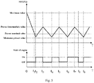
- Fig. 5 is a schematic diagram of a control strategy for switching between different driving modes according to one embodiment of the present invention.
- the controller 140 is configured to alternately switch between the first driving mode and the second driving mode according to a change in the remaining electric quantity of the power battery 11.
- the controller 140 sends a start instruction to the engine 31.
- the current driving mode is the second driving mode.
- the electric vehicle further comprises an energy management control apparatus for detecting the SOC value of the power battery 11 and processing the SOC value to send an instruction to the controller 140.
- the process by which the engine 31 receives a start instruction is: when the energy management control apparatus detects that the SOC value of the power battery 11 is greater than the minimum pre-set value and not greater than the nominal value, the controller 140 sends to the engine 31 an instruction for starting the engine 31, and once the engine 31 is started, the power battery 11 will be automatically deactivated. That is, the switching time for switching from the first driving mode to the second driving mode is short, so that the switching process is smooth, avoiding the lack of power or discomfort due to the switching of the driving mode.
- the maximum pre-set value and the minimum pre-set value in the present invention are not set to be the limit values of charging and discharging of the power battery 11, so that the state of charge of the power battery 11 is maintained within a prescribed range so as to prevent the state of charge of the power battery 11 from being too high or too low to improve the cycle life of the battery.
- the auxiliary energy apparatus 130 since the auxiliary energy apparatus 130 is used as the auxiliary energy source, not only the power battery 11 can be charged, but also the traction motor 21 can be directly driven, which is a prerequisite for selecting any energy source in the present application.
- the energy source in the present application may be alternately switched between the power battery 11 and the auxiliary energy apparatus 130.
- the frequency of use of the power battery 11 and the auxiliary energy 130 is greatly reduced, so as to prolong the service life of the power battery 11 while reduce the fuel consumption and improve the energy-saving performance.
- the driving mode may further comprise a third driving mode.
- Fig. 6 shows a schematic diagram of a driving principle of a third driving mode according to the embodiment, and as shown in Fig. 6 , in the third driving mode, the power battery 11 and the auxiliary energy apparatus 130 are both used as energy sources to drive the traction motor 21. It should be noted that all the conditions that the power demands of the entire vehicle cannot be satisfied when the driving mode is the first driving mode or the second driving mode can be taken as special conditions.
- the special conditions may comprise a condition of climbing a long ramp and a sudden acceleration condition.
- the condition of climbing a long ramp is a condition when a slope sensor 150 detects that the slope of a road in the travelling direction is greater than a pre-set slope value and the period of time when the slope is greater than the pre-set slope value exceeds a pre-set time, or is a condition when an acceleration sensor 160 detects that the acceleration change rate of the electric vehicle is greater than a pre-set value and the period of time when the acceleration change rate is greater than the pre-set value exceeds a certain time.
- the sudden acceleration condition is a condition when the acceleration sensor 160 detects that the acceleration change rate of the electric vehicle is greater than a pre-set value.
- the slope sensor 150 is used to detect a road slope at every moment in the travelling direction of the electric vehicle, and compare the slope data with the pre-set slope value, and when the slope data is greater than the pre-set slope value, the calculation for the period of time when the slope data is greater than the pre-set slope value is started.
- the acceleration sensor 160 is used to detect the acceleration of the electric vehicle at every moment, calculate the acceleration change rate at every moment, compare the acceleration change rate with the pre-set value, and, when the acceleration change rate is greater than the pre-set value, calculate the period of time when the acceleration change rate is greater than the pre-set value.
- the controller 140 is configured to, when the special condition is eliminated, switch the driving mode from the third driving mode to the driving mode before the occurrence of the condition of climbing a long ramp and/or the sudden acceleration condition.
- Fig. 5 shows a schematic diagram of switching the energy source of an electric vehicle between different driving modes according to one embodiment, and at the same time, shows a schematic diagram of switching the driving modes under special conditions.
- the driving mode is the first driving mode
- the driving mode is the second driving mode
- the alternating cycle between the first driving mode and the second driving mode is started hereafter. That is, during the time t 3 to t 4 and the time t 5 to t 6 , the driving mode is the first driving mode, and during the time t 4 to t 5 and the time t 6 to t 7 , the driving mode is the second driving mode. Since the electric vehicle is in a special condition, it is required to satisfy the power performance of the entire vehicle.
- the driving mode is the third driving mode, that is, the power battery 11 and the auxiliary energy apparatus 130 are simultaneously used as the energy sources to drive the motor 21.
- the driving mode becomes the driving mode that the vehicle has before the special condition occurs, that is, during the time t 8 to t 9 , the driving mode is the first driving mode.
- the SOC value of the power battery 11 is less than the minimum pre-set value, it is necessary to check whether the electric vehicle has a fault. This is because when the SOC value of the power battery 11 reaches the minimum value, the auxiliary energy apparatus 130 charges the power battery 11, and under normal conditions, the case where the SOC value of the power battery 11 is less than the minimum pre-set value does not occur.
- the energy management control apparatus is configured to, when the SOC value of the power battery 11 is less than the minimum pre-set value, determine that the electric vehicle is in a fault condition, and determine whether the auxiliary energy apparatus 130 is allowed to be in a start-up state, according to the fault codes of various parts of the entire vehicle, including the battery system, in combination with the fault condition. If not allowed, an instruction to enter a limp home mode or a parking mode is sent to the controller 140, waiting for the rescue. If allowed, an instruction to switch the driving mode to the second driving mode is sent to the controller 140, indicating that the electric vehicle is in a normal condition, and the auxiliary energy apparatus 130 can drive the running of the vehicle and charge the power battery 11.
- the present invention further provides a power source switching control method, comprising the following steps:
- Fig. 7 shows a schematic flow chart of a power source switching control method according to one embodiment of the present invention. As shown in Fig. 7 , the method may comprise the following steps:
- the driving mode is alternately switched between the first driving mode and the second driving mode; and the pre-set nominal value is selected as any percentage within 18-25%, and the pre-set intermediate value is selected as any percentage within 40-80%.
- Fig. 8 shows a schematic flow chart of a power source switching control method of another embodiment of the present invention.
- the power source switching control method of the present invention may comprise the following steps:
- the second driving mode is selected.
- the method further repeats steps S210 to S230.
- the power source switching control method of the present invention may comprise the following steps (not shown in the figures):
Abstract
Description
- The invention relates to the field of energy management and control of electric vehicles, in particular to a power source for an electric vehicle and a power source selection method.
- In order to improve the driving range performance of an electric vehicle, a power follower capable of increasing the driving range is installed in the extended-range electric vehicle. The power follower comprises an engine and an electric generator, and the power follower can not only charge a power battery, but also directly drive a traction motor, for example, a fuel cell engine, an internal combustion engine and the like. The principle that the power follower increases the driving range performance of the electric vehicle is: when the power battery is fully charged, the vehicle is running in an electric-only mode; and when the battery power is low, the power follower starts to work to charge the power battery or directly drive the traction motor, thus greatly increasing the mileage of the electric vehicle.
- For the power follower in the prior art, the control strategy of the energy source is that the power follower is used as a main energy source, while the power battery is used as an auxiliary backup energy source.
Fig. 1 shows a schematic diagram of a control strategy between a power follower and a power battery in the prior art. It can be seen fromFig. 1 that, when the battery power is reduced to a nominal value, the engine in the power follower is activated to drive the motor, the battery discharge for driving the motor is stopped, and at the same time the battery is charged. Although this control strategy has the advantages of small battery capacity, light weight, low battery charge and discharge frequency, low energy loss, long service life and the like, since only the power follower is used as the main energy source once the battery power is reduced to a certain value, this control strategy has high fuel consumption and poor energy-saving performance. - An object of the present invention is to provide a power source for an electric vehicle to solve the problems in the prior art, such as short battery life, and high fuel consumption and poor energy-saving performance due to the use of a power follower as an energy source.
- The invention provides a power source for an electric vehicle, the power source comprising:
- a power battery used to output electric power as a main energy source to drive a traction motor of the electric vehicle;
- an auxiliary energy apparatus used to output electric power as an auxiliary energy source to selectively drive the traction motor of the electric vehicle and/or charge the power battery; and
- a controller used to select any one mode to control the operation of the power battery and the auxiliary energy apparatus from multiple driving modes, wherein the multiple driving modes comprise:
- a first driving mode, in which the power battery operates alone to drive the traction motor; and
- a second driving mode, in which the auxiliary energy apparatus operates alone to drive the traction motor and to charge the power battery; and
- wherein the controller is configured to: select, when the remaining electric quantity of the power battery is not greater than a pre-set nominal value, the second driving mode until the remaining electric quantity of the power battery rises to a value which is not lower than a pre-set intermediate value; and select, when the remaining electric quantity of the power battery is not lower than the pre-set intermediate value, the first driving mode until the remaining electric quantity of the power battery is reduced to a value which is not greater than the pre-set nominal value, wherein the power battery has a maximum pre-set value which indicates that the power battery is substantially in a fully charged state, and the pre-set intermediate value is a value which is between the maximum pre-set value and the pre-set nominal value.
- Further, in the first driving mode, the auxiliary energy apparatus is deactivated.
- Further, in the second driving mode, the power battery is deactivated to stop outputting electric power.
- Further, the remaining electric quantity of the power battery is represented by an SOC value; and the auxiliary energy apparatus is a power follower.
- Further, the controller is configured to control the driving mode to alternately switch between the first driving mode and the second driving mode.
- Further, the multiple driving modes further comprise:
- a third driving mode, in which the power battery and the auxiliary energy apparatus both output electric power to simultaneously drive the traction motor;
- wherein the controller is configured to select the third driving mode when the instantaneous power demand of the electric vehicle cannot be satisfied when the current driving mode is the first driving mode or the second driving mode, and correspondingly return to the original first driving mode or second driving mode when the instantaneous power demand of the electric vehicle falls back.
- Further, the controller is configured to determine a battery failure when the remaining electric quantity of the power battery is reduced to a value which is not greater than a minimum pre-set value, and further determine whether the second driving mode is allowed to be selected,
if not allowed, it enters a limp home mode or a parking mode; and
if allowed, the second driving mode is selected. - Further, the minimum pre-set value indicates that the power battery is substantially in a dead battery state; and
the pre-set nominal value is between the maximum pre-set value and the minimum pre-set value and is close to the minimum pre-set value. - Further, the maximum pre-set value is 80-100%;
the minimum pre-set value is 15-18%;
the pre-set nominal value is 18-25%; and
the pre-set intermediate value is 40-80%. - In particular, the present invention further provides a power source switching control method, comprising the following steps:
- using a power battery to output electric power as a main energy source to drive a traction motor of the electric vehicle;
- using an auxiliary energy apparatus to output electric power as an auxiliary energy source to selectively drive the traction motor of the electric vehicle and/or charge the power battery; and
- selecting any one mode to control the operation of the power battery and the auxiliary energy apparatus from multiple driving modes, wherein the multiple driving modes comprise:
- a first driving mode, in which the power battery operates alone to drive the traction motor; and
- a second driving mode, in which the auxiliary energy apparatus operates alone to drive the traction motor and to charge the power battery; and
- wherein, when the remaining electric quantity of the power battery is not greater than a pre-set nominal value, the second driving mode is selected until the remaining electric quantity of the power battery rises to a value which is not lower than a pre-set intermediate value; and when the remaining electric quantity of the power battery is not lower than the pre-set intermediate value, the first driving mode is selected until the remaining electric quantity of the power battery is reduced to a value which is not greater than the pre-set nominal value, wherein the power battery has a maximum pre-set value which indicates that the power battery is substantially in a fully charged state, and the pre-set intermediate value is a value which is between the maximum pre-set value and the pre-set nominal value.
- In the solution of the present invention, the auxiliary energy apparatus may not only charge the battery but also directly drive the motor, which is a prerequisite for selecting any energy source in the present application. Compared with the prior art, the energy source in the present application may be selected between a power battery and an auxiliary energy source. As a result, the power battery and the auxiliary energy source are alternately used, so that the frequency of use of both of them is greatly reduced, so as to prolong the battery life while reduce the fuel consumption and improve the energy-saving performance. Furthermore, the maximum pre-set value and the minimum pre-set value in the present invention are not set to be the limit values of charging and discharging of the power battery, so that the state of charge of the power battery is maintained within a prescribed range so as to prevent the state of charge of the battery from being too high or too low to improve the cycle life of the battery.
- According to the solution of the present invention, since the pre-set nominal values are set, the selection process between the different driving modes is made smoother, and there is no lack of power or discomfort due to changes in the driving mode. In addition, due to the addition of the third driving mode, sufficient power can be ensured under special conditions, such as sudden acceleration or climbing a long ramp. The solution of the present invention also considers fault conditions, that is, when the remaining electric quantity of the power battery is reduced to a value which is not greater than the minimum pre-set value, it can be determined that the electric vehicle is in a fault condition, and at this time, it can be determined whether the second driving mode is allowed to be enabled, according to the fault codes of parts of the entire vehicle, including the battery system, in combination with the fault condition; if not allowed, it enters the limp home mode or the parking mode; and if allowed, the second driving mode is selected. This enables the fault condition to be detected in time so as to ensure the normal operation of the electric vehicle.
- According to the detailed description of specific embodiments of the invention below in conjunction with the accompanying drawings, the above and other objectives, advantages and features will become more apparent to a person skilled in the art.
- Some of specific embodiments of the invention will be described below in detail with reference to the accompanying drawings by way of example but not by way of limitation. The same reference signs indicate the same or similar components or parts in the accompanying drawings. It is understood by a person skilled in the art that the accompanying drawings are not necessarily drawn to scale. In the accompanying drawings:
-
Fig. 1 is a schematic diagram of a control strategy between a power follower and a power battery in the prior art; -
Fig. 2 is a general structural block diagram of a power source for an electric vehicle according to one embodiment of the present invention; -
Fig. 3 is a schematic diagram of a driving principle of a first driving mode according to one embodiment of the present invention; -
Fig. 4 is a schematic diagram of a driving principle of a second driving mode according to one embodiment of the present invention; -
Fig. 5 is a schematic diagram of a control strategy for switching between different driving modes according to one embodiment of the present invention; -
Fig. 6 is a schematic diagram of a driving principle of a third driving mode according to one embodiment of the present invention; -
Fig. 7 is a schematic flow chart of a power source switching control method according to one embodiment of the present invention; -
Fig. 8 is a schematic flow chart of a power source switching control method according to another embodiment of the present invention. -
Fig. 2 is a general structural block diagram of apower source 100 for an electric vehicle according to one embodiment of the present invention. As shown inFig. 2 , thepower source 100 for an electric vehicle may generally comprise abattery control apparatus 110, amotor control apparatus 120, anauxiliary energy apparatus 130, and acontroller 140, which are disposed within the electric vehicle. Thebattery control apparatus 110 may comprise apower battery 11 and apower battery controller 12 for controlling charging and/or discharging of thepower battery 11, thepower battery 11 being electrically connected to thepower battery controller 12. Themotor control apparatus 120 may comprise atraction motor 21 for drivingwheels 170 and amotor controller 22 for converting direct current to alternating current, thetraction motor 21 being electrically connected to themotor controller 22. Theauxiliary energy apparatus 130 comprises anengine 31, anelectric generator 32, and arectifier 33 for converting alternating current into direct current, which are disposed in the electric vehicle, theengine 31 being connected to theelectric generator 32, and theelectric generator 32 being electrically connected to therectifier 33. Thecontroller 140 is electrically connected to therectifier 33, themotor controller 22, and thepower battery controller 12 via a CAN (Controller Area Network) bus, respectively. It can be understood that, in order to detect the acceleration of the electric vehicle and the slope of the current road, thepower source 100 for the electric vehicle may further comprise anacceleration sensor 160 and aslope sensor 150, theacceleration sensor 160 and theslope sensor 150 being electrically connected to thecontroller 140, respectively. Theauxiliary energy apparatus 130 may directly drive thetraction motor 21 or may charge thepower battery 11. In one embodiment, theauxiliary energy apparatus 130 may be a power follower. In other embodiments, theauxiliary energy apparatus 130 may be another energy source apparatus capable of charging thepower battery 11 while directly driving thetraction motor 21. By using theauxiliary energy apparatus 130 and thepower battery 11 as energy sources, thepower battery 11 can be used as little as possible, thus reducing the cost of the entire energy supply system. - In order to select one of the
power battery 11 and theauxiliary energy apparatus 130 as the energy source, in one embodiment, the driving mode in the solution of the present invention may comprise a first driving mode and a second driving mode.Fig. 3 shows a schematic diagram of a driving principle of a first driving mode according to the embodiment, and as shown inFig. 3 , in the first driving mode, thepower battery 11 is used as an energy source to drive thetraction motor 21 and further drive running of thewheels 170.Fig. 4 shows a schematic diagram of a driving principle of a second driving mode according to the embodiment, and as shown inFig. 4 , in the second driving mode, theauxiliary energy apparatus 130 is used as an auxiliary energy source to drive thetraction motor 21 and supply power to thepower battery 11. Theauxiliary energy apparatus 130 can be configured to preferentially drive thetraction motor 21 and then supply power to thepower battery 11. Thecontroller 140 is configured to select the second driving mode when the remaining electric quantity of thepower battery 11 is not greater than a pre-set nominal value, until the remaining electric quantity of thepower battery 11 rises to a value which is not lower than a pre-set intermediate value; and when the remaining electric quantity of thepower battery 11 is not lower than the pre-set intermediate value, the first driving mode is selected until the remaining electric quantity of thepower battery 11 is reduced to a value which is not greater than the pre-set nominal value, wherein the power battery has a maximum pre-set value which indicates that the power battery is substantially in a fully charged state, and the pre-set intermediate value is a value which is between the maximum pre-set value and the pre-set nominal value. In a specific implementation, the maximum pre-set value is selected as any percentage within 80-100%, the pre-set nominal value is selected as any percentage within 18-25%, and the pre-set intermediate value is selected as any percentage within 40-80%. The remaining electric quantity can be represented by the SOC value, but is not limited thereby. The "SOC" described herein is an abbreviation of "State of Charge", which indicates the state of charge, and can also be understood as the state of battery power. In the solution of the present application, when the battery is fully charged, the driving energy source for the entire vehicle is provided by thepower battery 11; when the battery power is reduced to a certain value, the driving energy source for the entire vehicle is provided by theauxiliary energy apparatus 130; when the battery power rises to the pre-set intermediate value due to the charging of theauxiliary energy apparatus 130, the driving energy source for the entire vehicle is provided by thepower battery 11 instead; and when the entire vehicle is in a special condition, such as climbing a long ramp and/or sudden acceleration, the driving energy source for the entire vehicle is jointly provided by thepower battery 11 and theauxiliary energy apparatus 130. Since theauxiliary energy apparatus 130 also charges thepower battery 11 while driving thetraction motor 21, the remaining electric quantity of thepower battery 11 has a low-to-high charging process, and once thepower battery 11 is used, the electric quantity of thepower battery 11 has a high-to-low discharge process, thereby switching the energy source between different driving modes. -
Fig. 5 is a schematic diagram of a control strategy for switching between different driving modes according to one embodiment of the present invention. As shown inFig. 5 , thecontroller 140 is configured to alternately switch between the first driving mode and the second driving mode according to a change in the remaining electric quantity of thepower battery 11. When the SOC value of thepower battery 11 is greater than the minimum pre-set value and not greater than the nominal value, thecontroller 140 sends a start instruction to theengine 31. When theengine 31 is started, the current driving mode is the second driving mode. In general, the electric vehicle further comprises an energy management control apparatus for detecting the SOC value of thepower battery 11 and processing the SOC value to send an instruction to thecontroller 140. Therefore, the process by which theengine 31 receives a start instruction is: when the energy management control apparatus detects that the SOC value of thepower battery 11 is greater than the minimum pre-set value and not greater than the nominal value, thecontroller 140 sends to theengine 31 an instruction for starting theengine 31, and once theengine 31 is started, thepower battery 11 will be automatically deactivated. That is, the switching time for switching from the first driving mode to the second driving mode is short, so that the switching process is smooth, avoiding the lack of power or discomfort due to the switching of the driving mode. Furthermore, the maximum pre-set value and the minimum pre-set value in the present invention are not set to be the limit values of charging and discharging of thepower battery 11, so that the state of charge of thepower battery 11 is maintained within a prescribed range so as to prevent the state of charge of thepower battery 11 from being too high or too low to improve the cycle life of the battery. - In the solution of the present invention, since the
auxiliary energy apparatus 130 is used as the auxiliary energy source, not only thepower battery 11 can be charged, but also thetraction motor 21 can be directly driven, which is a prerequisite for selecting any energy source in the present application. Compared with the prior art, the energy source in the present application may be alternately switched between thepower battery 11 and theauxiliary energy apparatus 130. As a result, the frequency of use of thepower battery 11 and theauxiliary energy 130 is greatly reduced, so as to prolong the service life of thepower battery 11 while reduce the fuel consumption and improve the energy-saving performance. - During the driving of the vehicle, some special conditions, such as climbing a long ramp and/or sudden acceleration, may not be avoided, and therefore in order to satisfy the power performance under the special conditions, the driving mode may further comprise a third driving mode.
Fig. 6 shows a schematic diagram of a driving principle of a third driving mode according to the embodiment, and as shown inFig. 6 , in the third driving mode, thepower battery 11 and theauxiliary energy apparatus 130 are both used as energy sources to drive thetraction motor 21. It should be noted that all the conditions that the power demands of the entire vehicle cannot be satisfied when the driving mode is the first driving mode or the second driving mode can be taken as special conditions. The special conditions may comprise a condition of climbing a long ramp and a sudden acceleration condition. The condition of climbing a long ramp is a condition when aslope sensor 150 detects that the slope of a road in the travelling direction is greater than a pre-set slope value and the period of time when the slope is greater than the pre-set slope value exceeds a pre-set time, or is a condition when anacceleration sensor 160 detects that the acceleration change rate of the electric vehicle is greater than a pre-set value and the period of time when the acceleration change rate is greater than the pre-set value exceeds a certain time. The sudden acceleration condition is a condition when theacceleration sensor 160 detects that the acceleration change rate of the electric vehicle is greater than a pre-set value. Theslope sensor 150 is used to detect a road slope at every moment in the travelling direction of the electric vehicle, and compare the slope data with the pre-set slope value, and when the slope data is greater than the pre-set slope value, the calculation for the period of time when the slope data is greater than the pre-set slope value is started. Theacceleration sensor 160 is used to detect the acceleration of the electric vehicle at every moment, calculate the acceleration change rate at every moment, compare the acceleration change rate with the pre-set value, and, when the acceleration change rate is greater than the pre-set value, calculate the period of time when the acceleration change rate is greater than the pre-set value. In addition, thecontroller 140 is configured to, when the special condition is eliminated, switch the driving mode from the third driving mode to the driving mode before the occurrence of the condition of climbing a long ramp and/or the sudden acceleration condition. -
Fig. 5 shows a schematic diagram of switching the energy source of an electric vehicle between different driving modes according to one embodiment, and at the same time, shows a schematic diagram of switching the driving modes under special conditions. As shown inFig. 5 , when T = 0, the remaining electric quantity of thepower battery 11 is at the maximum value, and the remaining electric quantity of thepower battery 11 is gradually reduced with the consumption of the electric quantity of thepower battery 11; when T = t1, the remaining electric quantity of thepower battery 11 is at a pre-set nominal value, and theengine 31 is in a to-be-started state; and when T = t2, the remaining electric quantity of thepower battery 11 is between the pre-set nominal value and the minimum pre-set value, and theengine 31 is started. Therefore, during thetime 0 to t2, the driving mode is the first driving mode, during the time t2 to t3, the driving mode is the second driving mode, and the alternating cycle between the first driving mode and the second driving mode is started hereafter. That is, during the time t3 to t4 and the time t5 to t6, the driving mode is the first driving mode, and during the time t4 to t5 and the time t6 to t7, the driving mode is the second driving mode. Since the electric vehicle is in a special condition, it is required to satisfy the power performance of the entire vehicle. Therefore, during the time t7 to t8, the driving mode is the third driving mode, that is, thepower battery 11 and theauxiliary energy apparatus 130 are simultaneously used as the energy sources to drive themotor 21. Once the special condition disappears, the driving mode becomes the driving mode that the vehicle has before the special condition occurs, that is, during the time t8 to t9, the driving mode is the first driving mode. - In order to ensure the safety during the driving of the electric vehicle, when the SOC value of the
power battery 11 is less than the minimum pre-set value, it is necessary to check whether the electric vehicle has a fault. This is because when the SOC value of thepower battery 11 reaches the minimum value, theauxiliary energy apparatus 130 charges thepower battery 11, and under normal conditions, the case where the SOC value of thepower battery 11 is less than the minimum pre-set value does not occur. In the solution of the present invention, the energy management control apparatus is configured to, when the SOC value of thepower battery 11 is less than the minimum pre-set value, determine that the electric vehicle is in a fault condition, and determine whether theauxiliary energy apparatus 130 is allowed to be in a start-up state, according to the fault codes of various parts of the entire vehicle, including the battery system, in combination with the fault condition. If not allowed, an instruction to enter a limp home mode or a parking mode is sent to thecontroller 140, waiting for the rescue. If allowed, an instruction to switch the driving mode to the second driving mode is sent to thecontroller 140, indicating that the electric vehicle is in a normal condition, and theauxiliary energy apparatus 130 can drive the running of the vehicle and charge thepower battery 11. - In particular, the present invention further provides a power source switching control method, comprising the following steps:
- using a power battery to output electric power as a main energy source to drive a traction motor of an electric vehicle;
- using an auxiliary energy apparatus to output electric power as an auxiliary energy source to selectively drive the traction motor of the electric vehicle and/or charge the power battery; and
- selecting any one mode to control the operation of the power battery and the auxiliary energy apparatus from multiple driving modes, wherein the multiple driving modes comprise:
- a first driving mode, in which the power battery operates alone to drive the traction motor; and
- a second driving mode, in which the auxiliary energy apparatus operates alone to drive the traction motor and to charge the power battery; and
- wherein, when the remaining electric quantity of the power battery is not greater than a pre-set nominal value, the second driving mode is selected until the remaining electric quantity of the power battery rises to a value which is not lower than a pre-set intermediate value; and when the remaining electric quantity of the power battery is not lower than the pre-set intermediate value, the first driving mode is select until the remaining electric quantity of the power battery is reduced to a value which is not greater than the pre-set nominal value, wherein the power battery has a maximum pre-set value which indicates that the power battery is substantially in a fully charged state, and the pre-set intermediate value is a value which is between the maximum pre-set value and the pre-set nominal value.
-
Fig. 7 shows a schematic flow chart of a power source switching control method according to one embodiment of the present invention. As shown inFig. 7 , the method may comprise the following steps: - S110, when the SOC value of the power battery is not lower than the pre-set nominal value, the traction motor is driven in the first driving mode;
- S120, when the SOC value of the power battery is reduced to a value which is not greater than the pre-set nominal value, the driving mode is switched from the first driving mode to the second driving mode to drive the traction motor;
- S130, when the SOC value of the power battery rises to a value which is not lower than the pre-set intermediate value, the driving mode is switched from the second driving mode to the first driving mode to drive the traction motor; and
- S140, steps S110 to S130 are repeatedly performed.
- The driving mode is alternately switched between the first driving mode and the second driving mode; and
the pre-set nominal value is selected as any percentage within 18-25%, and the pre-set intermediate value is selected as any percentage within 40-80%. -
Fig. 8 shows a schematic flow chart of a power source switching control method of another embodiment of the present invention. In a specific implementation, it is possible to encounter a fault condition. In another embodiment, as shown inFig. 8 , the power source switching control method of the present invention may comprise the following steps: - S210, when the SOC value of the power battery is not lower than the pre-set nominal value, that is, when the SOC ≥ the nominal value (the default is SOC ≤ max), the traction motor is driven in the first driving mode;
- S220, when the SOC value of the power battery is reduced to a value which is less than the pre-set nominal value, that is, the SOC < the nominal value, the driving mode is switched from the first driving mode to the second driving mode to drive the traction motor;
- S230, when the SOC value of the power battery rises to a value which is not lower than the pre-set intermediate value, that is, the SOC ≥ the intermediate value, the driving mode is switched from the second driving mode to the first driving mode to drive the traction motor; and
- S240, when the SOC value of the power battery is reduced to a value which is not greater than the minimum pre-set value (min), that is, the SOC ≤ min, it is checked whether the electric vehicle is in a fault condition.
- If it is in a fault condition, it enters the limp home mode or the parking mode, waiting for rescue;
If it is not in a fault condition, the second driving mode is selected. - When the fault condition is eliminated or the fault condition does not occur, the method further repeats steps S210 to S230.
- Further, in a specific implementation, it is possible to encounter a special condition, for example, climbing a long ramp and/or sudden acceleration. In another embodiment, the power source switching control method of the present invention may comprise the following steps (not shown in the figures):
- S310, when the SOC value of the power battery is not lower than the pre-set nominal value, that is, when the SOC ≥ the nominal value (the default is SOC ≤ max), the traction motor is driven in the first driving mode;
- S320, when the SOC value of the power battery is reduced to a value which is less than the pre-set nominal value, that is, the SOC < the nominal value, the driving mode is switched from the first driving mode to the second driving mode to drive the traction motor;
- S330, when it rises to a value which is not lower than the pre-set intermediate value, that is, the SOC ≥ the intermediate value, the driving mode is switched from the second driving mode to the first driving mode to drive the traction motor;
- S340, steps S310 to S330 are repeatedly performed; and
- S350, when the instantaneous power demand of the entire vehicle is greater than the quantity of power generation of the auxiliary energy apparatus, the driving mode is switched from the second driving mode or the first driving mode to the third driving mode to drive the motor.
- Other features of the method of the present invention correspond to the above system features one-to-one and will not be described herein again.
- To this end, it is recognized by a person skilled in the art that although multiple exemplary embodiments of the present invention have been shown and described in detail herein, many other variations or modifications complying with the principles of the present invention can be directly determined or derived from the contents disclosed in the present invention without departing from the spirit and scope of the present invention. Therefore, the scope of the present invention should be construed and deemed as encompassing all these and other variations or modifications.
Claims (10)
- A power source for an electric vehicle, the power source comprising:a power battery used to output electric power as a main energy source to drive a traction motor of the electric vehicle;an auxiliary energy apparatus used to output electric power as an auxiliary energy source to selectively drive the traction motor of the electric vehicle and/or charge the power battery; anda controller used to select any one mode to control the operation of the power battery and the auxiliary energy apparatus from multiple driving modes, wherein the multiple driving modes comprise:a first driving mode, in which the power battery operates alone to drive the traction motor; anda second driving mode, in which the auxiliary energy apparatus operates alone to drive the traction motor and to charge the power battery; andwherein the controller is configured to: select, when the remaining electric quantity of the power battery is not greater than a pre-set nominal value, the second driving mode until the remaining electric quantity of the power battery rises to a value which is not lower than a pre-set intermediate value; and select, when the remaining electric quantity of the power battery is not lower than the pre-set intermediate value, the first driving mode until the remaining electric quantity of the power battery is reduced to a value which is not greater than the pre-set nominal value, wherein the power battery has a maximum pre-set value which indicates that the power battery is substantially in a fully charged state, and the pre-set intermediate value is a value which is between the maximum pre-set value and the pre-set nominal value.
- The power source according to claim 1, wherein, in the first driving mode, the auxiliary energy apparatus is deactivated.
- The power source according to claim 1 or 2, wherein, in the second driving mode, the power battery is deactivated to stop outputting electric power.
- The power source according to any one of claims 1 to 3, wherein the remaining electric quantity of the power battery is represented by an SOC value; and
the auxiliary energy apparatus is a power follower. - The power source according to claim 4, wherein the controller is configured to control the driving mode to alternately switch between the first driving mode and the second driving mode.
- The power source according to any one of claims 1 to 5, wherein the multiple driving modes further comprise:a third driving mode, in which the power battery and the auxiliary energy apparatus both output electric power to simultaneously drive the traction motor; andwherein the controller is configured to select the third driving mode when the instantaneous power demand of the electric vehicle cannot be satisfied when the current driving mode is the first driving mode or the second driving mode, and correspondingly return to the original first driving mode or second driving mode when the instantaneous power demand of the electric vehicle falls back.
- The power source according to any one of claims 1 to 6, wherein the controller is configured to determine a battery failure when the remaining electric quantity of the power battery is reduced to a value which is not greater than a minimum pre-set value, and further determine whether the second driving mode is allowed to be selected,
if not allowed, it enters a limp home mode or a parking mode; and
if allowed, the second driving mode is selected. - The power source according to claim 7, wherein the minimum pre-set value indicates that the power battery is substantially in a dead battery state; and
the pre-set nominal value is between the maximum pre-set value and the minimum pre-set value and is close to the minimum pre-set value. - The power source according to claim 8, wherein the maximum pre-set value is 80-100%;
the minimum pre-set value is 15-18%;
the pre-set nominal value is 18-25%; and
the pre-set intermediate value is 40-80%. - A power source selection method, comprising the following steps:using a power battery to output electric power as a main energy source to drive a traction motor of an electric vehicle;using an auxiliary energy apparatus to output electric power as an auxiliary energy source to selectively drive the traction motor of the electric vehicle and/or charge the power battery; andselecting any one mode to control the operation of the power battery and the auxiliary energy apparatus from multiple driving modes, wherein the multiple driving modes comprise:a first driving mode, in which the power battery operates alone to drive the traction motor; anda second driving mode, in which the auxiliary energy apparatus operates alone to drive the traction motor and to charge the power battery; andwherein, when the remaining electric quantity of the power battery is not greater than a pre-set nominal value, the second driving mode is selected until the remaining electric quantity of the power battery rises to a value which is not lower than a pre-set intermediate value; and when the remaining electric quantity of the power battery is not lower than the pre-set intermediate value, the first driving mode is selected until the remaining electric quantity of the power battery is reduced to a value which is not greater than the pre-set nominal value, wherein the power battery has a maximum pre-set value which indicates that the power battery is substantially in a fully charged state, and the pre-set intermediate value is a value which is between the maximum pre-set value and the pre-set nominal value.
Applications Claiming Priority (2)
| Application Number | Priority Date | Filing Date | Title |
|---|---|---|---|
| CN201610887313.2A CN106541940B (en) | 2016-10-11 | 2016-10-11 | A kind of power source and power source selection method for electric vehicle |
| PCT/CN2017/096655 WO2018068569A1 (en) | 2016-10-11 | 2017-08-09 | Power source for electric vehicle and power source selection method |
Publications (3)
| Publication Number | Publication Date |
|---|---|
| EP3505411A1 true EP3505411A1 (en) | 2019-07-03 |
| EP3505411A4 EP3505411A4 (en) | 2019-10-09 |
| EP3505411B1 EP3505411B1 (en) | 2022-05-18 |
Family
ID=58368610
Family Applications (1)
| Application Number | Title | Priority Date | Filing Date |
|---|---|---|---|
| EP17860562.2A Active EP3505411B1 (en) | 2016-10-11 | 2017-08-09 | Power source for electric vehicle and power source selection method |
Country Status (3)
| Country | Link |
|---|---|
| EP (1) | EP3505411B1 (en) |
| CN (1) | CN106541940B (en) |
| WO (1) | WO2018068569A1 (en) |
Families Citing this family (10)
| Publication number | Priority date | Publication date | Assignee | Title |
|---|---|---|---|---|
| CN106347145B (en) * | 2016-10-11 | 2018-12-25 | 浙江吉利新能源商用车有限公司 | For the power follower of electric vehicle and the control device and method of power battery |
| CN106541940B (en) * | 2016-10-11 | 2019-03-19 | 浙江吉利新能源商用车有限公司 | A kind of power source and power source selection method for electric vehicle |
| CN108944409A (en) * | 2018-06-12 | 2018-12-07 | 广州汽车集团股份有限公司 | Novel hybrid coupling mechanism and hybrid power control method, device |
| CN109263631B (en) * | 2018-11-19 | 2020-04-24 | 吉林大学 | Power limiting method for power source of hybrid electric vehicle |
| CN109910678B (en) * | 2019-03-25 | 2021-03-30 | 爱驰汽车有限公司 | Energy charging system, method, device and storage medium for vehicle-mounted dual-source battery pack |
| CN109823231A (en) * | 2019-03-25 | 2019-05-31 | 爱驰汽车有限公司 | Energy management system, method, equipment and the storage medium of vehicle-mounted double source battery pack |
| WO2020192708A1 (en) * | 2019-03-25 | 2020-10-01 | 爱驰汽车有限公司 | Energy management system and method for vehicle-mounted two-source battery pack |
| CN112092650B (en) * | 2020-08-24 | 2022-04-12 | 奇瑞新能源汽车股份有限公司 | Range-extending electric vehicle and control method, device and storage medium thereof |
| CN113183742A (en) * | 2021-04-29 | 2021-07-30 | 吉林大学 | Energy-saving concrete mixer truck driving system and control method thereof |
| CN115139815B (en) * | 2022-06-27 | 2024-04-09 | 重庆金康赛力斯新能源汽车设计院有限公司 | Torque distribution method, device, equipment and storage medium |
Family Cites Families (21)
| Publication number | Priority date | Publication date | Assignee | Title |
|---|---|---|---|---|
| US6814170B2 (en) * | 2001-07-18 | 2004-11-09 | Nissan Motor Co., Ltd. | Hybrid vehicle |
| JP2008087516A (en) * | 2006-09-29 | 2008-04-17 | Toyota Motor Corp | Hybrid vehicle and drive control method of the same |
| US8978798B2 (en) * | 2007-10-12 | 2015-03-17 | Odyne Systems, Llc | Hybrid vehicle drive system and method and idle reduction system and method |
| JP2012101616A (en) * | 2010-11-09 | 2012-05-31 | Denso Corp | Control device of series hybrid vehicle |
| DE102011102423A1 (en) * | 2011-05-24 | 2012-11-29 | Audi Ag | Method for operating a motor vehicle |
| CN102358285B (en) * | 2011-08-19 | 2014-01-01 | 北京汽车新能源汽车有限公司 | Range-extending electric vehicle control system and method |
| WO2013044357A1 (en) * | 2011-09-26 | 2013-04-04 | Magna E-Car Systems Of America, Inc. | Control strategies for state of charge of battery pack for electric vehicle with range extender |
| CN102555812B (en) * | 2012-01-11 | 2013-12-18 | 中联重科股份有限公司 | Energy control system and energy control method for electric vehicle |
| CN102582411A (en) * | 2012-03-06 | 2012-07-18 | 浙江吉利汽车研究院有限公司 | Hybrid driving system and corresponding hybrid driving method |
| CN103909922A (en) * | 2012-12-31 | 2014-07-09 | 上海大郡动力控制技术有限公司 | Vehicle control strategy of series hybrid electric vehicle |
| CN104163114B (en) * | 2014-07-22 | 2016-06-08 | 浙江大学 | A kind of car load energy management method for internal combustion power generating mileage increasing type electric vehicle |
| JP5961233B2 (en) * | 2014-09-29 | 2016-08-02 | 富士重工業株式会社 | Vehicle control device and vehicle |
| WO2016053786A1 (en) * | 2014-10-01 | 2016-04-07 | Ballard Power Systems Inc. | Multi-mode hybrid control for range-extended plug-in vehicles |
| CN104393355B (en) * | 2014-10-27 | 2016-08-24 | 潍柴动力股份有限公司 | The electric equilibrium control method of a kind of electrokinetic cell and device |
| CN105799694B (en) * | 2014-12-31 | 2019-03-29 | 比亚迪股份有限公司 | Control method, system and the vehicle of vehicle |
| CN105292108A (en) * | 2015-10-29 | 2016-02-03 | 北京新能源汽车股份有限公司 | Hybrid electric vehicle, control system and control method thereof |
| CN105946600B (en) * | 2016-05-04 | 2018-06-22 | 中国第一汽车股份有限公司 | Series connection stroke boosting power system of electric automobile and its control method |
| CN105922986B (en) * | 2016-05-24 | 2018-10-16 | 北京新能源汽车股份有限公司 | Stroke-increasing electric automobile and its mode switch control method and system |
| CN106541940B (en) * | 2016-10-11 | 2019-03-19 | 浙江吉利新能源商用车有限公司 | A kind of power source and power source selection method for electric vehicle |
| CN106347358B (en) * | 2016-10-11 | 2019-03-19 | 浙江吉利新能源商用车有限公司 | A kind of power source and power source method for handover control for electric vehicle |
| CN106347145B (en) * | 2016-10-11 | 2018-12-25 | 浙江吉利新能源商用车有限公司 | For the power follower of electric vehicle and the control device and method of power battery |
-
2016
- 2016-10-11 CN CN201610887313.2A patent/CN106541940B/en active Active
-
2017
- 2017-08-09 WO PCT/CN2017/096655 patent/WO2018068569A1/en unknown
- 2017-08-09 EP EP17860562.2A patent/EP3505411B1/en active Active
Also Published As
| Publication number | Publication date |
|---|---|
| EP3505411B1 (en) | 2022-05-18 |
| CN106541940B (en) | 2019-03-19 |
| CN106541940A (en) | 2017-03-29 |
| EP3505411A4 (en) | 2019-10-09 |
| WO2018068569A1 (en) | 2018-04-19 |
Similar Documents
| Publication | Publication Date | Title |
|---|---|---|
| EP3505411B1 (en) | Power source for electric vehicle and power source selection method | |
| CN110040038B (en) | Energy management control method and system for hydrogen-electricity hybrid fuel cell passenger car | |
| KR101863737B1 (en) | Electric power storage system | |
| KR101684543B1 (en) | System and method for driving mode control of hybrid vehicle | |
| CN106347358B (en) | A kind of power source and power source method for handover control for electric vehicle | |
| KR102000771B1 (en) | System and method for managing the electrical powering of at least one piece of equipment during the automatic restarting of an internal combustion engine of a vehicle | |
| EP2634035A1 (en) | Power supply apparatus for electric vehicle, method of controlling power supply apparatus, and electric vehicle | |
| KR101927176B1 (en) | Method and device for controlling output of low voltage DC-DC converter in environmentally friendly vehicle | |
| CN108340794A (en) | The control device and electric vehicle of electric vehicle | |
| JP2016027980A (en) | Vehicle power source device | |
| EP3505386A1 (en) | Power follower for electric vehicle, and control apparatus and method for power battery | |
| CN109715426B (en) | Method for operating a hybrid vehicle | |
| CN106167021B (en) | Method and control device for recovering energy in a hybrid vehicle | |
| KR20130069001A (en) | Electric vehicle and control method thereof | |
| WO2016125852A1 (en) | Vehicle power-source device and vehicle-power-source-device control method | |
| JP2017229132A (en) | Power supply unit for vehicle and power supply controller | |
| AU2011200023A1 (en) | Apparatus and Method for Controlling Oil Pump of Plug-in Hybrid Electronic Vehicle | |
| US20140288803A1 (en) | Vehicle With Engine Start-Stop Device and Method of Operating Same | |
| JP2010081762A (en) | Vehicle power supply | |
| JP2019209811A (en) | Battery diagnosis device | |
| JP2013189161A (en) | Hybrid vehicle and electric power supply method for hybrid vehicle | |
| JP2004108226A (en) | Engine idle stop device and engine idle stop method | |
| KR20150121639A (en) | Controlling circuit for Hybrid Electric Vehicle and Controlling method thereof | |
| JP2007300774A (en) | Controller of fuel cell vehicle | |
| JP2012091770A (en) | Method and device for protecting battery of hybrid vehicle |
Legal Events
| Date | Code | Title | Description |
|---|---|---|---|
| STAA | Information on the status of an ep patent application or granted ep patent |
Free format text: STATUS: THE INTERNATIONAL PUBLICATION HAS BEEN MADE |
|
| PUAI | Public reference made under article 153(3) epc to a published international application that has entered the european phase |
Free format text: ORIGINAL CODE: 0009012 |
|
| STAA | Information on the status of an ep patent application or granted ep patent |
Free format text: STATUS: REQUEST FOR EXAMINATION WAS MADE |
|
| 17P | Request for examination filed |
Effective date: 20190327 |
|
| AK | Designated contracting states |
Kind code of ref document: A1 Designated state(s): AL AT BE BG CH CY CZ DE DK EE ES FI FR GB GR HR HU IE IS IT LI LT LU LV MC MK MT NL NO PL PT RO RS SE SI SK SM TR |
|
| AX | Request for extension of the european patent |
Extension state: BA ME |
|
| STAA | Information on the status of an ep patent application or granted ep patent |
Free format text: STATUS: EXAMINATION IS IN PROGRESS |
|
| A4 | Supplementary search report drawn up and despatched |
Effective date: 20190910 |
|
| RIC1 | Information provided on ipc code assigned before grant |
Ipc: B60W 20/50 20160101ALI20190904BHEP Ipc: B60W 20/13 20160101ALI20190904BHEP Ipc: B60K 6/46 20071001ALI20190904BHEP Ipc: B60W 10/06 20060101AFI20190904BHEP |
|
| 17Q | First examination report despatched |
Effective date: 20190920 |
|
| STAA | Information on the status of an ep patent application or granted ep patent |
Free format text: STATUS: EXAMINATION IS IN PROGRESS |
|
| DAV | Request for validation of the european patent (deleted) | ||
| DAX | Request for extension of the european patent (deleted) | ||
| STAA | Information on the status of an ep patent application or granted ep patent |
Free format text: STATUS: EXAMINATION IS IN PROGRESS |
|
| GRAP | Despatch of communication of intention to grant a patent |
Free format text: ORIGINAL CODE: EPIDOSNIGR1 |
|
| STAA | Information on the status of an ep patent application or granted ep patent |
Free format text: STATUS: GRANT OF PATENT IS INTENDED |
|
| INTG | Intention to grant announced |
Effective date: 20211221 |
|
| GRAS | Grant fee paid |
Free format text: ORIGINAL CODE: EPIDOSNIGR3 |
|
| GRAA | (expected) grant |
Free format text: ORIGINAL CODE: 0009210 |
|
| STAA | Information on the status of an ep patent application or granted ep patent |
Free format text: STATUS: THE PATENT HAS BEEN GRANTED |
|
| AK | Designated contracting states |
Kind code of ref document: B1 Designated state(s): AL AT BE BG CH CY CZ DE DK EE ES FI FR GB GR HR HU IE IS IT LI LT LU LV MC MK MT NL NO PL PT RO RS SE SI SK SM TR |
|
| REG | Reference to a national code |
Ref country code: GB Ref legal event code: FG4D |
|
| REG | Reference to a national code |
Ref country code: CH Ref legal event code: EP |
|
| REG | Reference to a national code |
Ref country code: IE Ref legal event code: FG4D |
|
| REG | Reference to a national code |
Ref country code: DE Ref legal event code: R096 Ref document number: 602017057717 Country of ref document: DE |
|
| REG | Reference to a national code |
Ref country code: AT Ref legal event code: REF Ref document number: 1492997 Country of ref document: AT Kind code of ref document: T Effective date: 20220615 |
|
| REG | Reference to a national code |
Ref country code: SE Ref legal event code: TRGR |
|
| REG | Reference to a national code |
Ref country code: LT Ref legal event code: MG9D |
|
| REG | Reference to a national code |
Ref country code: NL Ref legal event code: MP Effective date: 20220518 |
|
| REG | Reference to a national code |
Ref country code: AT Ref legal event code: MK05 Ref document number: 1492997 Country of ref document: AT Kind code of ref document: T Effective date: 20220518 |
|
| PG25 | Lapsed in a contracting state [announced via postgrant information from national office to epo] |
Ref country code: PT Free format text: LAPSE BECAUSE OF FAILURE TO SUBMIT A TRANSLATION OF THE DESCRIPTION OR TO PAY THE FEE WITHIN THE PRESCRIBED TIME-LIMIT Effective date: 20220919 Ref country code: NO Free format text: LAPSE BECAUSE OF FAILURE TO SUBMIT A TRANSLATION OF THE DESCRIPTION OR TO PAY THE FEE WITHIN THE PRESCRIBED TIME-LIMIT Effective date: 20220818 Ref country code: NL Free format text: LAPSE BECAUSE OF FAILURE TO SUBMIT A TRANSLATION OF THE DESCRIPTION OR TO PAY THE FEE WITHIN THE PRESCRIBED TIME-LIMIT Effective date: 20220518 Ref country code: LT Free format text: LAPSE BECAUSE OF FAILURE TO SUBMIT A TRANSLATION OF THE DESCRIPTION OR TO PAY THE FEE WITHIN THE PRESCRIBED TIME-LIMIT Effective date: 20220518 Ref country code: HR Free format text: LAPSE BECAUSE OF FAILURE TO SUBMIT A TRANSLATION OF THE DESCRIPTION OR TO PAY THE FEE WITHIN THE PRESCRIBED TIME-LIMIT Effective date: 20220518 Ref country code: GR Free format text: LAPSE BECAUSE OF FAILURE TO SUBMIT A TRANSLATION OF THE DESCRIPTION OR TO PAY THE FEE WITHIN THE PRESCRIBED TIME-LIMIT Effective date: 20220819 Ref country code: FI Free format text: LAPSE BECAUSE OF FAILURE TO SUBMIT A TRANSLATION OF THE DESCRIPTION OR TO PAY THE FEE WITHIN THE PRESCRIBED TIME-LIMIT Effective date: 20220518 Ref country code: ES Free format text: LAPSE BECAUSE OF FAILURE TO SUBMIT A TRANSLATION OF THE DESCRIPTION OR TO PAY THE FEE WITHIN THE PRESCRIBED TIME-LIMIT Effective date: 20220518 Ref country code: BG Free format text: LAPSE BECAUSE OF FAILURE TO SUBMIT A TRANSLATION OF THE DESCRIPTION OR TO PAY THE FEE WITHIN THE PRESCRIBED TIME-LIMIT Effective date: 20220818 Ref country code: AT Free format text: LAPSE BECAUSE OF FAILURE TO SUBMIT A TRANSLATION OF THE DESCRIPTION OR TO PAY THE FEE WITHIN THE PRESCRIBED TIME-LIMIT Effective date: 20220518 |
|
| PG25 | Lapsed in a contracting state [announced via postgrant information from national office to epo] |
Ref country code: RS Free format text: LAPSE BECAUSE OF FAILURE TO SUBMIT A TRANSLATION OF THE DESCRIPTION OR TO PAY THE FEE WITHIN THE PRESCRIBED TIME-LIMIT Effective date: 20220518 Ref country code: PL Free format text: LAPSE BECAUSE OF FAILURE TO SUBMIT A TRANSLATION OF THE DESCRIPTION OR TO PAY THE FEE WITHIN THE PRESCRIBED TIME-LIMIT Effective date: 20220518 Ref country code: LV Free format text: LAPSE BECAUSE OF FAILURE TO SUBMIT A TRANSLATION OF THE DESCRIPTION OR TO PAY THE FEE WITHIN THE PRESCRIBED TIME-LIMIT Effective date: 20220518 Ref country code: IS Free format text: LAPSE BECAUSE OF FAILURE TO SUBMIT A TRANSLATION OF THE DESCRIPTION OR TO PAY THE FEE WITHIN THE PRESCRIBED TIME-LIMIT Effective date: 20220918 |
|
| PG25 | Lapsed in a contracting state [announced via postgrant information from national office to epo] |
Ref country code: SM Free format text: LAPSE BECAUSE OF FAILURE TO SUBMIT A TRANSLATION OF THE DESCRIPTION OR TO PAY THE FEE WITHIN THE PRESCRIBED TIME-LIMIT Effective date: 20220518 Ref country code: SK Free format text: LAPSE BECAUSE OF FAILURE TO SUBMIT A TRANSLATION OF THE DESCRIPTION OR TO PAY THE FEE WITHIN THE PRESCRIBED TIME-LIMIT Effective date: 20220518 Ref country code: RO Free format text: LAPSE BECAUSE OF FAILURE TO SUBMIT A TRANSLATION OF THE DESCRIPTION OR TO PAY THE FEE WITHIN THE PRESCRIBED TIME-LIMIT Effective date: 20220518 Ref country code: EE Free format text: LAPSE BECAUSE OF FAILURE TO SUBMIT A TRANSLATION OF THE DESCRIPTION OR TO PAY THE FEE WITHIN THE PRESCRIBED TIME-LIMIT Effective date: 20220518 Ref country code: DK Free format text: LAPSE BECAUSE OF FAILURE TO SUBMIT A TRANSLATION OF THE DESCRIPTION OR TO PAY THE FEE WITHIN THE PRESCRIBED TIME-LIMIT Effective date: 20220518 Ref country code: CZ Free format text: LAPSE BECAUSE OF FAILURE TO SUBMIT A TRANSLATION OF THE DESCRIPTION OR TO PAY THE FEE WITHIN THE PRESCRIBED TIME-LIMIT Effective date: 20220518 |
|
| REG | Reference to a national code |
Ref country code: DE Ref legal event code: R097 Ref document number: 602017057717 Country of ref document: DE |
|
| REG | Reference to a national code |
Ref country code: DE Ref legal event code: R119 Ref document number: 602017057717 Country of ref document: DE |
|
| PLBE | No opposition filed within time limit |
Free format text: ORIGINAL CODE: 0009261 |
|
| STAA | Information on the status of an ep patent application or granted ep patent |
Free format text: STATUS: NO OPPOSITION FILED WITHIN TIME LIMIT |
|
| PG25 | Lapsed in a contracting state [announced via postgrant information from national office to epo] |
Ref country code: MC Free format text: LAPSE BECAUSE OF FAILURE TO SUBMIT A TRANSLATION OF THE DESCRIPTION OR TO PAY THE FEE WITHIN THE PRESCRIBED TIME-LIMIT Effective date: 20220518 Ref country code: AL Free format text: LAPSE BECAUSE OF FAILURE TO SUBMIT A TRANSLATION OF THE DESCRIPTION OR TO PAY THE FEE WITHIN THE PRESCRIBED TIME-LIMIT Effective date: 20220518 |
|
| REG | Reference to a national code |
Ref country code: CH Ref legal event code: PL |
|
| 26N | No opposition filed |
Effective date: 20230221 |
|
| PG25 | Lapsed in a contracting state [announced via postgrant information from national office to epo] |
Ref country code: LU Free format text: LAPSE BECAUSE OF NON-PAYMENT OF DUE FEES Effective date: 20220809 Ref country code: LI Free format text: LAPSE BECAUSE OF NON-PAYMENT OF DUE FEES Effective date: 20220831 Ref country code: CH Free format text: LAPSE BECAUSE OF NON-PAYMENT OF DUE FEES Effective date: 20220831 |
|
| REG | Reference to a national code |
Ref country code: BE Ref legal event code: MM Effective date: 20220831 |
|
| PG25 | Lapsed in a contracting state [announced via postgrant information from national office to epo] |
Ref country code: SI Free format text: LAPSE BECAUSE OF FAILURE TO SUBMIT A TRANSLATION OF THE DESCRIPTION OR TO PAY THE FEE WITHIN THE PRESCRIBED TIME-LIMIT Effective date: 20220518 |
|
| PG25 | Lapsed in a contracting state [announced via postgrant information from national office to epo] |
Ref country code: IE Free format text: LAPSE BECAUSE OF NON-PAYMENT OF DUE FEES Effective date: 20220809 Ref country code: DE Free format text: LAPSE BECAUSE OF NON-PAYMENT OF DUE FEES Effective date: 20230301 |
|
| PG25 | Lapsed in a contracting state [announced via postgrant information from national office to epo] |
Ref country code: BE Free format text: LAPSE BECAUSE OF NON-PAYMENT OF DUE FEES Effective date: 20220831 |
|
| PGFP | Annual fee paid to national office [announced via postgrant information from national office to epo] |
Ref country code: GB Payment date: 20230824 Year of fee payment: 7 |
|
| PGFP | Annual fee paid to national office [announced via postgrant information from national office to epo] |
Ref country code: SE Payment date: 20230816 Year of fee payment: 7 Ref country code: FR Payment date: 20230831 Year of fee payment: 7 |
|
| PG25 | Lapsed in a contracting state [announced via postgrant information from national office to epo] |
Ref country code: IT Free format text: LAPSE BECAUSE OF FAILURE TO SUBMIT A TRANSLATION OF THE DESCRIPTION OR TO PAY THE FEE WITHIN THE PRESCRIBED TIME-LIMIT Effective date: 20220518 |
|
| PG25 | Lapsed in a contracting state [announced via postgrant information from national office to epo] |
Ref country code: HU Free format text: LAPSE BECAUSE OF FAILURE TO SUBMIT A TRANSLATION OF THE DESCRIPTION OR TO PAY THE FEE WITHIN THE PRESCRIBED TIME-LIMIT; INVALID AB INITIO Effective date: 20170809 |