EP3505326A1 - Apparatus for engraving weakening lines and related process - Google Patents
Apparatus for engraving weakening lines and related process Download PDFInfo
- Publication number
- EP3505326A1 EP3505326A1 EP19150115.4A EP19150115A EP3505326A1 EP 3505326 A1 EP3505326 A1 EP 3505326A1 EP 19150115 A EP19150115 A EP 19150115A EP 3505326 A1 EP3505326 A1 EP 3505326A1
- Authority
- EP
- European Patent Office
- Prior art keywords
- support
- cutting
- engraving
- flexible material
- cutting edge
- Prior art date
- Legal status (The legal status is an assumption and is not a legal conclusion. Google has not performed a legal analysis and makes no representation as to the accuracy of the status listed.)
- Granted
Links
Images




Classifications
-
- B—PERFORMING OPERATIONS; TRANSPORTING
- B29—WORKING OF PLASTICS; WORKING OF SUBSTANCES IN A PLASTIC STATE IN GENERAL
- B29C—SHAPING OR JOINING OF PLASTICS; SHAPING OF MATERIAL IN A PLASTIC STATE, NOT OTHERWISE PROVIDED FOR; AFTER-TREATMENT OF THE SHAPED PRODUCTS, e.g. REPAIRING
- B29C59/00—Surface shaping of articles, e.g. embossing; Apparatus therefor
- B29C59/007—Forming single grooves or ribs, e.g. tear lines, weak spots
-
- B—PERFORMING OPERATIONS; TRANSPORTING
- B26—HAND CUTTING TOOLS; CUTTING; SEVERING
- B26D—CUTTING; DETAILS COMMON TO MACHINES FOR PERFORATING, PUNCHING, CUTTING-OUT, STAMPING-OUT OR SEVERING
- B26D3/00—Cutting work characterised by the nature of the cut made; Apparatus therefor
- B26D3/08—Making a superficial cut in the surface of the work without removal of material, e.g. scoring, incising
- B26D3/085—On sheet material
-
- B—PERFORMING OPERATIONS; TRANSPORTING
- B26—HAND CUTTING TOOLS; CUTTING; SEVERING
- B26D—CUTTING; DETAILS COMMON TO MACHINES FOR PERFORATING, PUNCHING, CUTTING-OUT, STAMPING-OUT OR SEVERING
- B26D7/00—Details of apparatus for cutting, cutting-out, stamping-out, punching, perforating, or severing by means other than cutting
- B26D7/27—Means for performing other operations combined with cutting
-
- B—PERFORMING OPERATIONS; TRANSPORTING
- B60—VEHICLES IN GENERAL
- B60R—VEHICLES, VEHICLE FITTINGS, OR VEHICLE PARTS, NOT OTHERWISE PROVIDED FOR
- B60R21/00—Arrangements or fittings on vehicles for protecting or preventing injuries to occupants or pedestrians in case of accidents or other traffic risks
- B60R21/02—Occupant safety arrangements or fittings, e.g. crash pads
- B60R21/16—Inflatable occupant restraints or confinements designed to inflate upon impact or impending impact, e.g. air bags
- B60R21/20—Arrangements for storing inflatable members in their non-use or deflated condition; Arrangement or mounting of air bag modules or components
- B60R21/215—Arrangements for storing inflatable members in their non-use or deflated condition; Arrangement or mounting of air bag modules or components characterised by the covers for the inflatable member
- B60R21/2165—Arrangements for storing inflatable members in their non-use or deflated condition; Arrangement or mounting of air bag modules or components characterised by the covers for the inflatable member characterised by a tear line for defining a deployment opening
-
- B—PERFORMING OPERATIONS; TRANSPORTING
- B29—WORKING OF PLASTICS; WORKING OF SUBSTANCES IN A PLASTIC STATE IN GENERAL
- B29L—INDEXING SCHEME ASSOCIATED WITH SUBCLASS B29C, RELATING TO PARTICULAR ARTICLES
- B29L2031/00—Other particular articles
- B29L2031/30—Vehicles, e.g. ships or aircraft, or body parts thereof
- B29L2031/3005—Body finishings
- B29L2031/3038—Air bag covers
Definitions
- the present invention relates to an apparatus for engraving weakening lines on flexible materials intended for forming airbag covers and to a related cutting process.
- the invention is preferably applicable in the sector of cutting upholstery materials intended for covering dashboards, doors and elements of a vehicle in which airbag devices are installed.
- Airbags are usually coupled to an underlying plastic bearing and covered (for aesthetic reasons) by an upholstery material of various kinds (e.g. synthetic leather and similar plastic sheets).
- the materials normally used include, for example, elastomers based on polyurethane, PVC, thermoplastic elastomers and the like.
- the weakening lines are made on the upholstery material through scoring (not through cuts) that leave at the engraved line itself a specific residual thickness of uncut material, which is less than the total thickness of the upholstery material.
- Such residual (uncut) thickness has a direct impact on the exit speed and method of the airbag and therefore directly influences the safety of the vehicle; in fact, it is intuitive that a residual thickness that is too high can cause the failed or incorrect exit of the airbag membrane; in the event in which the residual thickness were lower than that established in the design, the damage would - potentially - be even greater; in fact the membrane (encountering lower resistance than the design resistance) would exit at the wrong time, with the risk not only of making the presence of the airbag futile, but also causing serious damage to the passenger.
- the use of automatic cutting machines is known, for example robots with a high degree of repeatability, that move a cutting tool with respect to a support, i.e. a bearing on which the upholstery material for scoring is to be positioned;
- the support is equipped with devices for securing the upholstery: in a known example, the support is a bearing (variously shaped) provided with a resting surface for the upholstery, to which a plurality of suction conduits lead, connected to a pump or the like. Once positioned on the support, the upholstery is securely retained there by suction.
- a sensor is used mounted on the cutting tool that measures the distance between the latter and the support.
- the cutting tool provided with a cutting edge, bears a sensor, usually mounted side by side to the cutting edge, which measures the distance (from the sensor) to the support, thus approximating the distance between the cutting edge and the support.
- the measured distance is not exactly the one between the distal part of the cutting edge and the support, but only an approximation thereof: since this distance equates to the considered as residual thickness, this inevitably entails measurement errors.
- the support usually does not have a flat shape, but is variously shaped to conform to the shapes of the dashboard or - more generally - of the part of automobile where the flexible bearing being processed will be mounted.
- the small size of the errors permitted in the measurement/verification of the residual material thicknesses is kept in consideration, which is usually in the order of tens, if not thousandths, of a millimeter.
- the main task of the present invention consists of realising an apparatus and a related process for engraving weakening lines of flexible materials intended to form covers of airbags that solves the technical problem set out above, obviates the drawbacks and overcomes the limits of the prior art, allowing a technique to be provided able to perform highly precise measurements.
- An additional purpose of the invention is to realise an apparatus and a related process for engraving weakening lines that is able to avoid approximations in the measurement.
- An additional purpose of the invention is to realise an apparatus and a related process for engraving weakening lines that is able to take into consideration the wear of the cutting edge.
- a further purpose of the invention is to realise an apparatus and a related process for engraving weakening lines that is relatively easy to realise and economically competitive compared with the prior art.
- an apparatus for engraving weakening lines of flexible materials intended to form covers of airbags comprising:
- An additional object of the invention is a process as described below.
- the apparatus 1 is shown lacking parts that are not fundamental to understand the invention, for example lacking the frame, the motors and the actuating means of the cutting head (for example, robot arms, portal structures or the like), because they are known to the person skilled in the art and not useful for the purposes of the present description.
- the apparatus 1 comprises a cutting head 2 in turn provided with a cutting edge 3, for example a cutting blade.
- the cutting edge 3 is mounted integral with the head 2, so that when it is displaced the cutting edge 3 follows it in its displacement; the cutting edge 3 is preferably replaceable, so that it can be changed when its wear conditions make it appropriate.
- the apparatus 1 then comprises a support 4 for the flexible material; the support 4 comprises an outer surface 42 variously shaped in space, so as to adapt to the different shapes of the flexible materials that in turn are specifically made so as to adapt to the dashboards, to the doors or to other parts of a vehicle on which they will be mounted.
- the support 4 optionally comprises a device for holding in position the sheet of flexible material, for example a suction device, that creates a vacuum between sheet and outer surface 42; this device for holding in position comprises for example a plurality of micro-holes and/or a perimetral gasket and suction holes that open on the surface 42.
- a suction device for holding in position the sheet of flexible material
- this device for holding in position comprises for example a plurality of micro-holes and/or a perimetral gasket and suction holes that open on the surface 42.
- the cutting head 2 is movable with respect to the support 4 so as to follow a cutting trajectory for engraving the weakening lines on the sheet of flexible material being processed.
- the head 2 could be mounted on a robot arm or on a frame, for example a portal frame, that is motorised, not shown in the accompanying figures.
- the apparatus 1 comprises at least two proximity sensors 5 integral with the support 4 and arranged along said cutting trajectory, each configured to measure the distance between it and the cutting edge 3.
- the number of the proximity sensors 5 is established as a function of different operating parameters selected on the basis of the characteristics of the individual operation to be performed (for example, complexity of the cutting trajectory, length thereof, type of material, etc.); to a higher number of proximity sensors 5 corresponds a higher number of control point, so that in theory it is advantageous to increase the number up to a maximum, allowed by size and costs.
- the cutting edge 3 is metallic and the proximity sensors 5 are inductive sensors.
- These sensors 5 are able to measure the distance between their terminal detection end 51 and a metallic object, in this case the distal portion (or terminal end) of the cutting edge 3.
- the sensors 5 could be capacitive or magnetic sensors, able to detect the metal of the cutting edge through the layer of (non-metallic) material being processed.
- the support 4 comprises housing seats 41, recessed with respect to the outer surface 42 for supporting the flexible material on the support 4; in the seats 41 are housed the sensors 5, so as not to interfere with the cutting or engraving operation.
- each proximity sensor 5 is substantially flush with said outer surface 42 of the support 4; between the terminal detection end 51 and the cutting edge 3 is not interposed any metallic element and more preferably any element in general, so as not to distort the measurement of the sensor 5.
- the cutting head 2 comprises a feeler device 8.
- the feeler device 8 comprises a movable measurement rod 81 that extends substantially parallel to the cutting edge 3 and allows to take a measurement by means of contact.
- Said feeler device 8 is used for example in a step of preliminary calibration of the apparatus 1: in this step the head 2 follows the cutting trajectory on the support 4 (in the absence of material to be cut) and the feeler follows the same path that would be followed by the cutting edge in working condition.
- the feeler device 8 Since the feeler device 8 is mechanically actuated and measure by means of contact, it, in the path followed in the calibration step, moves with the (metallic) head of the rod 81 of the feeler 8 in (sliding) contact with the surface of the support 4.
- the feeler 8 passes by a sensor 5, the latter measures the distance with the (metallic) head of the rod 81 of the feeler 8.
- each sensor 5 measures the respective distance DF with respect to the surface of the support 4 itself, i.e. a calibration measurement DF for each sensor 5.
- Said calibration measurement (physical distance, DF) is stored by the apparatus (preferably by its control unit) and subtracted from each measurement taken (measured distance, DM) by the sensor that is carried out during an operating step of cutting.
- SR DM-DF
- control unit in operating communication with the proximity sensors 5 for the transmission of data representative of measurements carried out during the cutting or engraving step: optionally, the control unit is also in communication with the feeler device 8, if present.
- control unit comprises a comparing device, able to compare the measurements taken by the sensors 5 with pre-set reference measurements, so as to identify whether the measured residual thickness is compatible with the design thickness and to validate (or not) the operation of engraving the weakening lines.
- a comparing device able to compare the measurements taken by the sensors 5 with pre-set reference measurements, so as to identify whether the measured residual thickness is compatible with the design thickness and to validate (or not) the operation of engraving the weakening lines.
- this allows to take sampled measurements (at each sensor) of the residual thickness of the sheet of material at portions of the cutting trajectory.
- the method then provides for each measuring phase to be carried out by means of a proximity sensor 5 integral with the support 4, still more preferably by means of an inductive sensor.
- the process comprises a preliminary calibration step, carried out before the phase a. (i.e. before the phase a. belonging to a cutting operation or to a multiplicity of cutting operations) which comprises the phases of:
- the measurement instead is a direct measurement, which determines the distance between the distal end of the cutting edge and the support.
- the measurement of the residual thickness takes place simultaneously with the cutting edge, i.e. during the passage of the cutting edge on the material, so as to avoid subsequent checking or verification operations that could entail wasted time and/or additional measurement errors.
- the materials used may be any depending on the needs.
Landscapes
- Engineering & Computer Science (AREA)
- Mechanical Engineering (AREA)
- Life Sciences & Earth Sciences (AREA)
- Forests & Forestry (AREA)
- Air Bags (AREA)
- Branch Pipes, Bends, And The Like (AREA)
- Electrical Discharge Machining, Electrochemical Machining, And Combined Machining (AREA)
Abstract
Description
- The present invention relates to an apparatus for engraving weakening lines on flexible materials intended for forming airbag covers and to a related cutting process.
- The invention is preferably applicable in the sector of cutting upholstery materials intended for covering dashboards, doors and elements of a vehicle in which airbag devices are installed.
- Airbags are usually coupled to an underlying plastic bearing and covered (for aesthetic reasons) by an upholstery material of various kinds (e.g. synthetic leather and similar plastic sheets).
- The materials normally used include, for example, elastomers based on polyurethane, PVC, thermoplastic elastomers and the like.
- For the purpose of allowing the correct opening of the airbag, it is necessary to provide weakening lines in the upholstery material, at which the upholstery is intended to break upon the exit of the airbag membrane; this allows the airbag to be correctly directed towards the passenger to be protected and to comply with the technical opening times.
- The weakening lines are made on the upholstery material through scoring (not through cuts) that leave at the engraved line itself a specific residual thickness of uncut material, which is less than the total thickness of the upholstery material.
- Such residual (uncut) thickness has a direct impact on the exit speed and method of the airbag and therefore directly influences the safety of the vehicle; in fact, it is intuitive that a residual thickness that is too high can cause the failed or incorrect exit of the airbag membrane; in the event in which the residual thickness were lower than that established in the design, the damage would - potentially - be even greater; in fact the membrane (encountering lower resistance than the design resistance) would exit at the wrong time, with the risk not only of making the presence of the airbag futile, but also causing serious damage to the passenger.
- To have maximum precision in the residual thickness the use of automatic cutting machines is known, for example robots with a high degree of repeatability, that move a cutting tool with respect to a support, i.e. a bearing on which the upholstery material for scoring is to be positioned; the support is equipped with devices for securing the upholstery: in a known example, the support is a bearing (variously shaped) provided with a resting surface for the upholstery, to which a plurality of suction conduits lead, connected to a pump or the like. Once positioned on the support, the upholstery is securely retained there by suction.
- In order to guarantee the correctness of the process, measurement checks of the residual thickness must be performed for every engraved line, the results of which checks are then documented in order to certify the correct performance of the engraved lines for each upholstery material.
- In this sense, recording measurements of residual thicknesses in determined check points through different systems from the robot that performed the engraved line are known, in order to guarantee the reliability of the check.
- To perform these check and verification measurements, different devices have been developed over time: in one example a sensor is used mounted on the cutting tool that measures the distance between the latter and the support.
- In this solution, the cutting tool, provided with a cutting edge, bears a sensor, usually mounted side by side to the cutting edge, which measures the distance (from the sensor) to the support, thus approximating the distance between the cutting edge and the support.
- However, this solution, though functional, does have some limitations.
- In the first place, the measured distance is not exactly the one between the distal part of the cutting edge and the support, but only an approximation thereof: since this distance equates to the considered as residual thickness, this inevitably entails measurement errors.
- These errors are more evident if one considers that the support usually does not have a flat shape, but is variously shaped to conform to the shapes of the dashboard or - more generally - of the part of automobile where the flexible bearing being processed will be mounted.
- An additional limit is tied to the fact that known apparatuses cannot take into consideration, in the measurement, a possible wear of the cutting edge, whose distal end becomes shorter, as it wears down.
- For correct understanding, the small size of the errors permitted in the measurement/verification of the residual material thicknesses is kept in consideration, which is usually in the order of tens, if not thousandths, of a millimeter.
- Another limit is tied to the fact that the sensors currently used are the inductive ones: the support must then be made so as to be detectable by the inductive sensor, hence of metal.
- The main task of the present invention consists of realising an apparatus and a related process for engraving weakening lines of flexible materials intended to form covers of airbags that solves the technical problem set out above, obviates the drawbacks and overcomes the limits of the prior art, allowing a technique to be provided able to perform highly precise measurements.
- An additional purpose of the invention is to realise an apparatus and a related process for engraving weakening lines that is able to avoid approximations in the measurement.
- An additional purpose of the invention is to realise an apparatus and a related process for engraving weakening lines that is able to take into consideration the wear of the cutting edge.
- A further purpose of the invention is to realise an apparatus and a related process for engraving weakening lines that is relatively easy to realise and economically competitive compared with the prior art.
- The task set forth above, as well as the aforementioned purposes and others that will be more readily apparent below, are achieved by an apparatus for engraving weakening lines of flexible materials intended to form covers of airbags, comprising:
- a cutting head provided with a cutting edge,
- a support for the flexible material,
- the cutting head being movable with respect to the support so as to follow a cutting trajectory for the engraving of said weakening lines on the flexible material being processed, which the apparatus comprises at least two proximity sensors integral with the support and positioned along said cutting trajectory, each configured to measure the distance between it and the cutting edge.
- An additional object of the invention is a process as described below.
- Thus it is possible to achieve the objects identified above, as the invention makes it possible to verify that the residual thickness of the uncut material is consistent with the design choices.
- Additional features and advantages will become more apparent from the description of a preferred, but non-exclusive embodiment of an apparatus that realises the process of the invention, illustrated by way of non-limiting example with the aid of the appended drawings, in which:
-
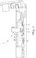
figure 1 is a top plan view of an embodiment of an apparatus according to the invention, with the section planes A-A and B-B are highlighted; -
figure 2 is a section view along the plane B-B of the apparatus offigure 1 ; -
figure 3 is a section view along the plane A-A of the apparatus offigure 1 ; -
figure 4 is a lateral view of the apparatus offig. 1 ; -
figure 5 is a detailed view of a detail offig. 3 . - Before describing the process according to the invention, for clarity purposes, it is worth describing the apparatus 1 in its non-limiting embodiment of the accompanying figures.
- With reference to the figures, they show an apparatus for engraving weakening lines of flexible materials intended to form airbag covers, indicated in its entirety with the numerical reference 1.
- The apparatus 1 is shown lacking parts that are not fundamental to understand the invention, for example lacking the frame, the motors and the actuating means of the cutting head (for example, robot arms, portal structures or the like), because they are known to the person skilled in the art and not useful for the purposes of the present description.
- The apparatus 1 comprises a
cutting head 2 in turn provided with acutting edge 3, for example a cutting blade. - The
cutting edge 3 is mounted integral with thehead 2, so that when it is displaced thecutting edge 3 follows it in its displacement; thecutting edge 3 is preferably replaceable, so that it can be changed when its wear conditions make it appropriate. - The apparatus 1 then comprises a
support 4 for the flexible material; thesupport 4 comprises anouter surface 42 variously shaped in space, so as to adapt to the different shapes of the flexible materials that in turn are specifically made so as to adapt to the dashboards, to the doors or to other parts of a vehicle on which they will be mounted. - The
support 4 optionally comprises a device for holding in position the sheet of flexible material, for example a suction device, that creates a vacuum between sheet andouter surface 42; this device for holding in position comprises for example a plurality of micro-holes and/or a perimetral gasket and suction holes that open on thesurface 42. This solution is generally known in itself in the technical sector and it will not be discussed any further. - The
cutting head 2 is movable with respect to thesupport 4 so as to follow a cutting trajectory for engraving the weakening lines on the sheet of flexible material being processed. - For this purpose, the
head 2 could be mounted on a robot arm or on a frame, for example a portal frame, that is motorised, not shown in the accompanying figures. - According to the invention, the apparatus 1 comprises at least two
proximity sensors 5 integral with thesupport 4 and arranged along said cutting trajectory, each configured to measure the distance between it and thecutting edge 3. - In this way it is possible to measure, by sampling, the distance between the distal end of the
cutting edge 3 and thesupport 4, representatives of the residual (uncut) thickness of the sheet of material. - In the preferred case, illustrated herein, there are six
proximity sensors 5 provided in different positions along the cutting trajectory; in other embodiments there are three, four, or a different number, even higher than six: the number of theproximity sensors 5 is established as a function of different operating parameters selected on the basis of the characteristics of the individual operation to be performed (for example, complexity of the cutting trajectory, length thereof, type of material, etc.); to a higher number ofproximity sensors 5 corresponds a higher number of control point, so that in theory it is advantageous to increase the number up to a maximum, allowed by size and costs. - Preferably, the
cutting edge 3 is metallic and theproximity sensors 5 are inductive sensors. - These
sensors 5 are able to measure the distance between theirterminal detection end 51 and a metallic object, in this case the distal portion (or terminal end) of thecutting edge 3. - In theory, equivalently, the
sensors 5 could be capacitive or magnetic sensors, able to detect the metal of the cutting edge through the layer of (non-metallic) material being processed. - Preferably, the
support 4 compriseshousing seats 41, recessed with respect to theouter surface 42 for supporting the flexible material on thesupport 4; in theseats 41 are housed thesensors 5, so as not to interfere with the cutting or engraving operation. - Preferably, to make the measurement even more precise (as well as to avoid interference of any type) the
terminal detection end 51 of eachproximity sensor 5 is substantially flush with saidouter surface 42 of thesupport 4; between theterminal detection end 51 and thecutting edge 3 is not interposed any metallic element and more preferably any element in general, so as not to distort the measurement of thesensor 5. - Advantageously and optionally the
cutting head 2 comprises afeeler device 8. - The
feeler device 8 comprises amovable measurement rod 81 that extends substantially parallel to thecutting edge 3 and allows to take a measurement by means of contact. - Said
feeler device 8 is used for example in a step of preliminary calibration of the apparatus 1: in this step thehead 2 follows the cutting trajectory on the support 4 (in the absence of material to be cut) and the feeler follows the same path that would be followed by the cutting edge in working condition. - Since the
feeler device 8 is mechanically actuated and measure by means of contact, it, in the path followed in the calibration step, moves with the (metallic) head of therod 81 of thefeeler 8 in (sliding) contact with the surface of thesupport 4. - When the
feeler 8 passes by asensor 5, the latter measures the distance with the (metallic) head of therod 81 of thefeeler 8. - Since the (metallic) head of the
rod 81 of thefeeler 8 is certainly in contact with the support 4 (for the aforesaid reasons), eachsensor 5 measures the respective distance DF with respect to the surface of thesupport 4 itself, i.e. a calibration measurement DF for eachsensor 5. - Said calibration measurement (physical distance, DF) is stored by the apparatus (preferably by its control unit) and subtracted from each measurement taken (measured distance, DM) by the sensor that is carried out during an operating step of cutting.
- This result is the real thickness SR of residual material that remains in the engraving operation or the real distance that exists between the surface of the support and the tip of the cutting edge and hence the real (not approximate) thickness of the material actually cut.
- In essence, SR=DM-DF.
- Preferably aboard the apparatus 1 is present a control unit, in operating communication with the
proximity sensors 5 for the transmission of data representative of measurements carried out during the cutting or engraving step: optionally, the control unit is also in communication with thefeeler device 8, if present. - Preferably the control unit comprises a comparing device, able to compare the measurements taken by the
sensors 5 with pre-set reference measurements, so as to identify whether the measured residual thickness is compatible with the design thickness and to validate (or not) the operation of engraving the weakening lines. - In the final analysis, this allows to take sampled measurements (at each sensor) of the residual thickness of the sheet of material at portions of the cutting trajectory.
- The operation of the invention, and the process thereof comprise at least the steps of:
- a. arranging a sheet of a flexible material
- b. locking said sheet of flexible material in position on a
support 4 of an engraving apparatus 1, preferably of the type described above, - c. engraving weakening lines on said sheet of flexible material using a
cutting edge 3 that progresses along a cutting trajectory - d. measuring a residual thickness of the sheet of flexible material not cut by the
cutting edge 3; according to the invention said measurement step d. comprises at least two measuring phases of a distance between a distal end of thecutting edge 3 and thesupport 4, each measuring phase being made at a different section of said cutting trajectory. - Preferably, as mentioned above, the method then provides for each measuring phase to be carried out by means of a
proximity sensor 5 integral with thesupport 4, still more preferably by means of an inductive sensor. - Optionally, if the
feeler device 8 is provided on the apparatus 1, the process comprises a preliminary calibration step, carried out before the phase a. (i.e. before the phase a. belonging to a cutting operation or to a multiplicity of cutting operations) which comprises the phases of: - i. moving the feeler along the cutting trajectory in the absence of flexible material being processed,
- ii. measuring by means of a
proximity sensor 5 integral with thesupport 4 the physical distance DF with respect to thefeeler 8 at the same sections of said cutting trajectory with respect to which the measurement referred to in d. takes place, - iii. storing said physical distance (DF) values of phase ii.
- If said preliminary calibration step is provided, the process further comprises a step for calculating the real thickness SR of residual material not cut, in which calculation step the real thickness is calculated, for each section of said cutting trajectory with respect to which the measurement referred to in d. takes place, said real thickness SR being equal to SR=DM-DF, where DM is the distance measured for each
sensor 5 at d. of the process and DF the physical distance measured by the feeler at phase ii. - From the above description, it is noted that with respect to the state of the art, where the measurement of the residual thickness was inferred on the basis of an indirect measurement (between head and support), in the case of the invention the measurement instead is a direct measurement, which determines the distance between the distal end of the cutting edge and the support.
- Moreover, the measurement of the residual thickness takes place simultaneously with the cutting edge, i.e. during the passage of the cutting edge on the material, so as to avoid subsequent checking or verification operations that could entail wasted time and/or additional measurement errors.
- This allows to avoid (or limit) measurement errors tied to the shape of the support and/or to the wear of the tool.
- In practice, it has been noted how the invention described herein and claimed below fulfils the task and the predefined objects as it allows the objects predefined above to be reached.
- The invention as it is conceived is susceptible to numerous modifications and variants, all falling within the scope of the inventive concept. Moreover, all details can be replaced with other technically equivalent elements.
- In practice, the materials used, provided they are compatible with the specific use, as well as the contingent dimensions and shapes, may be any depending on the needs.
Claims (11)
- Apparatus (1) for engraving the weakening lines of flexible materials intended to form airbag covers, comprising:a cutting head (2) provided with a cutting edge (3),a support (4) for the flexible material,the cutting head (2) being movable with respect to the support (4) so as to follow a cutting trajectory for the engraving of said weakening lines on the flexible material being processed,characterised in that:
the apparatus (1) comprises at least two proximity sensors (5) integral with the support (4) and arranged along said cutting trajectory, each configured to measure the distance between it and the cutting edge (3). - Engraving apparatus (1) according to claim 1, wherein said cutting edge (3) is made of metal and said at least two proximity sensors (5) are inductive sensors.
- Engraving apparatus (1) according to claim 1 or 2, wherein said support (4) comprises housing seats (41) recessed with respect to an outer surface (42) for supporting the flexible material on the support (4), said at least two proximity sensors (5) being mounted in said housing seats (41).
- Engraving apparatus (1) according to the preceding claim, wherein a detection end (51) of each proximity sensor (5) is substantially flush with said outer surface (42) of the support (4).
- Engraving apparatus (1) according to one or more of the preceding claims, wherein said cutting head (2) comprises a feeler device (8).
- Engraving apparatus (1) according to one or more of the preceding claims, comprising a control unit, said proximity sensors (5) being operatively connected to said control unit at least for the transmission of data representative of measurements made.
- Process for engraving the weakening lines of flexible materials intended to form airbag covers, comprising the steps of:a. arranging a sheet of a flexible materialb. locking said sheet of flexible material in position on a support (4) of an engraving apparatus (1)c. engraving weakening lines on said sheet of flexible material using a cutting edge (3) that progresses along a cutting trajectoryd. measuring a residual thickness of the sheet of flexible material which has not been cut by the cutting edge (3)characterised in that:
said measurement step d. comprises at least two measuring phases of a distance between a distal end of the cutting edge (3) and said support (4), each measuring phase being made at a different section of said cutting trajectory. - Process according to claim 7, wherein each measuring phase is carried out by means of a proximity sensor (5) integral with said support (4).
- Process according to claim 8, comprising a preliminary calibration step, carried out before step a., said preliminary calibration step comprising the phases of:i. moving the feeler (8) along the cutting trajectory in the absence of flexible material being processed,ii. measuring by means of the proximity sensor (5) integral with the support (4) a physical distance (DF) with respect to the feeler (8) at the same sections of said cutting trajectory with respect to which the measurement referred to in d. takes place,iii. storing said physical distance (DF) values of phase ii.
- Process according to claim 9, comprising a step for calculating the real thickness (SR) of residual material not cut, in which calculation step said real thickness (SR) is calculated, for each section of said cutting trajectory with respect to which the measurement referred to in d. takes place, said real thickness (SR) being equal to SR = DM-DF, where DM is the distance measured for each sensor (5) at d. of the process and DF the physical distance measured by the feeler at phase ii.
- Process according to one or more of claims 7 to 10, characterised in that it is carried out in an engraving apparatus (1) according to one or more of claims 1 to 6.
Applications Claiming Priority (1)
| Application Number | Priority Date | Filing Date | Title |
|---|---|---|---|
| IT201800000252A IT201800000252A1 (en) | 2018-01-02 | 2018-01-02 | EQUIPMENT FOR CUTTING BREAKAGE LINES AND RELATED PROCEDURE |
Publications (2)
| Publication Number | Publication Date |
|---|---|
| EP3505326A1 true EP3505326A1 (en) | 2019-07-03 |
| EP3505326B1 EP3505326B1 (en) | 2024-06-19 |
Family
ID=61873817
Family Applications (1)
| Application Number | Title | Priority Date | Filing Date |
|---|---|---|---|
| EP19150115.4A Active EP3505326B1 (en) | 2018-01-02 | 2019-01-02 | Apparatus for engraving weakening lines and related process |
Country Status (2)
| Country | Link |
|---|---|
| EP (1) | EP3505326B1 (en) |
| IT (1) | IT201800000252A1 (en) |
Cited By (1)
| Publication number | Priority date | Publication date | Assignee | Title |
|---|---|---|---|---|
| DE102022127797A1 (en) * | 2022-10-20 | 2024-04-25 | Faurecia Innenraum Systeme Gmbh | Machine tool and method for producing a vehicle interior trim part with material weakening |
Citations (4)
| Publication number | Priority date | Publication date | Assignee | Title |
|---|---|---|---|---|
| EP1621415A1 (en) * | 2004-07-29 | 2006-02-01 | Takata Corporation | Manufacturing apparatus for airbag cover |
| EP1693726A2 (en) * | 2005-02-22 | 2006-08-23 | GEISS Aktiengesellschaft | Device and method for providing lines of weakness in a stiff element |
| DE102007049849A1 (en) * | 2007-10-18 | 2009-04-23 | GM Global Technology Operations, Inc., Detroit | Airbag cover groove designing device for vehicle, has distance sensor i.e. laser scanner, designed for direct detection of distance between outer side lying opposite to inner side of interior-trim part, and distance sensor |
| US20150059143A1 (en) * | 2009-04-17 | 2015-03-05 | Nakata Coating Co., Ltd. | Vehicular interior member manufacturing method and airbag rupturing groove manufacturing method |
Family Cites Families (1)
| Publication number | Priority date | Publication date | Assignee | Title |
|---|---|---|---|---|
| DE102006034287B3 (en) * | 2006-07-21 | 2008-02-28 | Kraussmaffei Technologies Gmbh | Device for introducing weakening cuts into a film or skin |
-
2018
- 2018-01-02 IT IT201800000252A patent/IT201800000252A1/en unknown
-
2019
- 2019-01-02 EP EP19150115.4A patent/EP3505326B1/en active Active
Patent Citations (4)
| Publication number | Priority date | Publication date | Assignee | Title |
|---|---|---|---|---|
| EP1621415A1 (en) * | 2004-07-29 | 2006-02-01 | Takata Corporation | Manufacturing apparatus for airbag cover |
| EP1693726A2 (en) * | 2005-02-22 | 2006-08-23 | GEISS Aktiengesellschaft | Device and method for providing lines of weakness in a stiff element |
| DE102007049849A1 (en) * | 2007-10-18 | 2009-04-23 | GM Global Technology Operations, Inc., Detroit | Airbag cover groove designing device for vehicle, has distance sensor i.e. laser scanner, designed for direct detection of distance between outer side lying opposite to inner side of interior-trim part, and distance sensor |
| US20150059143A1 (en) * | 2009-04-17 | 2015-03-05 | Nakata Coating Co., Ltd. | Vehicular interior member manufacturing method and airbag rupturing groove manufacturing method |
Cited By (1)
| Publication number | Priority date | Publication date | Assignee | Title |
|---|---|---|---|---|
| DE102022127797A1 (en) * | 2022-10-20 | 2024-04-25 | Faurecia Innenraum Systeme Gmbh | Machine tool and method for producing a vehicle interior trim part with material weakening |
Also Published As
| Publication number | Publication date |
|---|---|
| IT201800000252A1 (en) | 2019-07-02 |
| EP3505326B1 (en) | 2024-06-19 |
Similar Documents
| Publication | Publication Date | Title |
|---|---|---|
| KR101424675B1 (en) | Apparatus for forming a weakening incision in a membrane or epidermis | |
| EP2253441B2 (en) | Method for squaring panels made of wood or the like | |
| US20180045536A1 (en) | On-Line Calibration Testing During The Operation Of An Autonomous Vehicle | |
| ES2611002T3 (en) | Forming device and procedure for the operation of a forming device | |
| CN110000608B (en) | Method for detecting at least one tool state of a tool of a machine tool for machining a workpiece, and machine tool | |
| US20090048713A1 (en) | Method and control device for targeted reaction in the event of a contact between a machine element of a machine and an object | |
| EP2645052B1 (en) | Measurement head for feeler for workpieces being machined | |
| US7598882B2 (en) | Safety device and method for an automatically operating installation having at least one moveable part | |
| EP3505326B1 (en) | Apparatus for engraving weakening lines and related process | |
| EP3635330B1 (en) | Control of flatness of metal sheets obtained by flattening and shearing uncoiled metal sheet webs | |
| CZ12039U1 (en) | Metal forming machine | |
| EP3278892B1 (en) | Equipment for the mechanical forming of sheet-shaped elements | |
| CN108252073A (en) | The cutter head assembly of cutter and the bearing calibration of cut-off knife cabling, controller | |
| US20060232791A1 (en) | Method and system for checking the position of a mechanical part with a light beam | |
| CN101200198A (en) | Device for position detection of a spoiler on a car | |
| EP3378615B1 (en) | Process and apparatus for scoring weakening lines | |
| KR101931966B1 (en) | Automatic cutting apparatus of injection gate in engine cover robot injection process | |
| US20150016912A1 (en) | Apparatus for sharpening beet-cutter knives | |
| EP2601012B1 (en) | Method for verifying tool integrity in automatic multi-tool key duplicating machines, and machine for implementing the method | |
| WO2009156566A1 (en) | Method and device for calibrating the position of blades of slitter- winder in fibrous-web machine | |
| JP5570241B2 (en) | Groove depth guarantee device and groove depth guarantee method | |
| JP6091065B2 (en) | GUAGING METHOD, GUAGING DEVICE, AND BENDING DEVICE | |
| KR100826314B1 (en) | Wire Stripping Machine and Wire Stripping System Using the Same | |
| JP5941685B2 (en) | Method for correcting teaching line of machining means | |
| CN119043104B (en) | A welding assembly inspection tool for rear crossbeam of automobile floor |
Legal Events
| Date | Code | Title | Description |
|---|---|---|---|
| PUAI | Public reference made under article 153(3) epc to a published international application that has entered the european phase |
Free format text: ORIGINAL CODE: 0009012 |
|
| STAA | Information on the status of an ep patent application or granted ep patent |
Free format text: STATUS: THE APPLICATION HAS BEEN PUBLISHED |
|
| AK | Designated contracting states |
Kind code of ref document: A1 Designated state(s): AL AT BE BG CH CY CZ DE DK EE ES FI FR GB GR HR HU IE IS IT LI LT LU LV MC MK MT NL NO PL PT RO RS SE SI SK SM TR |
|
| AX | Request for extension of the european patent |
Extension state: BA ME |
|
| STAA | Information on the status of an ep patent application or granted ep patent |
Free format text: STATUS: REQUEST FOR EXAMINATION WAS MADE |
|
| 17P | Request for examination filed |
Effective date: 20200103 |
|
| RBV | Designated contracting states (corrected) |
Designated state(s): AL AT BE BG CH CY CZ DE DK EE ES FI FR GB GR HR HU IE IS IT LI LT LU LV MC MK MT NL NO PL PT RO RS SE SI SK SM TR |
|
| STAA | Information on the status of an ep patent application or granted ep patent |
Free format text: STATUS: EXAMINATION IS IN PROGRESS |
|
| 17Q | First examination report despatched |
Effective date: 20220207 |
|
| RAP1 | Party data changed (applicant data changed or rights of an application transferred) |
Owner name: AUTOMATIONSROBOTIC GMBH |
|
| P01 | Opt-out of the competence of the unified patent court (upc) registered |
Effective date: 20230609 |
|
| RIC1 | Information provided on ipc code assigned before grant |
Ipc: B60R 21/2165 20110101ALN20231213BHEP Ipc: B26D 7/27 20060101ALI20231213BHEP Ipc: B26D 3/08 20060101ALI20231213BHEP Ipc: B29C 59/00 20060101AFI20231213BHEP |
|
| GRAP | Despatch of communication of intention to grant a patent |
Free format text: ORIGINAL CODE: EPIDOSNIGR1 |
|
| STAA | Information on the status of an ep patent application or granted ep patent |
Free format text: STATUS: GRANT OF PATENT IS INTENDED |
|
| RIC1 | Information provided on ipc code assigned before grant |
Ipc: B60R 21/2165 20110101ALN20240109BHEP Ipc: B26D 7/27 20060101ALI20240109BHEP Ipc: B26D 3/08 20060101ALI20240109BHEP Ipc: B29C 59/00 20060101AFI20240109BHEP |
|
| INTG | Intention to grant announced |
Effective date: 20240126 |
|
| GRAS | Grant fee paid |
Free format text: ORIGINAL CODE: EPIDOSNIGR3 |
|
| GRAA | (expected) grant |
Free format text: ORIGINAL CODE: 0009210 |
|
| STAA | Information on the status of an ep patent application or granted ep patent |
Free format text: STATUS: THE PATENT HAS BEEN GRANTED |
|
| AK | Designated contracting states |
Kind code of ref document: B1 Designated state(s): AL AT BE BG CH CY CZ DE DK EE ES FI FR GB GR HR HU IE IS IT LI LT LU LV MC MK MT NL NO PL PT RO RS SE SI SK SM TR |
|
| REG | Reference to a national code |
Ref country code: GB Ref legal event code: FG4D |
|
| REG | Reference to a national code |
Ref country code: CH Ref legal event code: EP |
|
| REG | Reference to a national code |
Ref country code: DE Ref legal event code: R096 Ref document number: 602019053803 Country of ref document: DE |
|
| PG25 | Lapsed in a contracting state [announced via postgrant information from national office to epo] |
Ref country code: BG Free format text: LAPSE BECAUSE OF FAILURE TO SUBMIT A TRANSLATION OF THE DESCRIPTION OR TO PAY THE FEE WITHIN THE PRESCRIBED TIME-LIMIT Effective date: 20240619 |
|
| PG25 | Lapsed in a contracting state [announced via postgrant information from national office to epo] |
Ref country code: FI Free format text: LAPSE BECAUSE OF FAILURE TO SUBMIT A TRANSLATION OF THE DESCRIPTION OR TO PAY THE FEE WITHIN THE PRESCRIBED TIME-LIMIT Effective date: 20240619 Ref country code: HR Free format text: LAPSE BECAUSE OF FAILURE TO SUBMIT A TRANSLATION OF THE DESCRIPTION OR TO PAY THE FEE WITHIN THE PRESCRIBED TIME-LIMIT Effective date: 20240619 |
|
| REG | Reference to a national code |
Ref country code: LT Ref legal event code: MG9D |
|
| PG25 | Lapsed in a contracting state [announced via postgrant information from national office to epo] |
Ref country code: GR Free format text: LAPSE BECAUSE OF FAILURE TO SUBMIT A TRANSLATION OF THE DESCRIPTION OR TO PAY THE FEE WITHIN THE PRESCRIBED TIME-LIMIT Effective date: 20240920 |
|
| REG | Reference to a national code |
Ref country code: NL Ref legal event code: MP Effective date: 20240619 |
|
| PG25 | Lapsed in a contracting state [announced via postgrant information from national office to epo] |
Ref country code: LV Free format text: LAPSE BECAUSE OF FAILURE TO SUBMIT A TRANSLATION OF THE DESCRIPTION OR TO PAY THE FEE WITHIN THE PRESCRIBED TIME-LIMIT Effective date: 20240619 |
|
| PG25 | Lapsed in a contracting state [announced via postgrant information from national office to epo] |
Ref country code: NO Free format text: LAPSE BECAUSE OF FAILURE TO SUBMIT A TRANSLATION OF THE DESCRIPTION OR TO PAY THE FEE WITHIN THE PRESCRIBED TIME-LIMIT Effective date: 20240919 Ref country code: LV Free format text: LAPSE BECAUSE OF FAILURE TO SUBMIT A TRANSLATION OF THE DESCRIPTION OR TO PAY THE FEE WITHIN THE PRESCRIBED TIME-LIMIT Effective date: 20240619 Ref country code: HR Free format text: LAPSE BECAUSE OF FAILURE TO SUBMIT A TRANSLATION OF THE DESCRIPTION OR TO PAY THE FEE WITHIN THE PRESCRIBED TIME-LIMIT Effective date: 20240619 Ref country code: GR Free format text: LAPSE BECAUSE OF FAILURE TO SUBMIT A TRANSLATION OF THE DESCRIPTION OR TO PAY THE FEE WITHIN THE PRESCRIBED TIME-LIMIT Effective date: 20240920 Ref country code: FI Free format text: LAPSE BECAUSE OF FAILURE TO SUBMIT A TRANSLATION OF THE DESCRIPTION OR TO PAY THE FEE WITHIN THE PRESCRIBED TIME-LIMIT Effective date: 20240619 Ref country code: BG Free format text: LAPSE BECAUSE OF FAILURE TO SUBMIT A TRANSLATION OF THE DESCRIPTION OR TO PAY THE FEE WITHIN THE PRESCRIBED TIME-LIMIT Effective date: 20240619 Ref country code: RS Free format text: LAPSE BECAUSE OF FAILURE TO SUBMIT A TRANSLATION OF THE DESCRIPTION OR TO PAY THE FEE WITHIN THE PRESCRIBED TIME-LIMIT Effective date: 20240919 |
|
| PG25 | Lapsed in a contracting state [announced via postgrant information from national office to epo] |
Ref country code: NL Free format text: LAPSE BECAUSE OF FAILURE TO SUBMIT A TRANSLATION OF THE DESCRIPTION OR TO PAY THE FEE WITHIN THE PRESCRIBED TIME-LIMIT Effective date: 20240619 |
|
| REG | Reference to a national code |
Ref country code: AT Ref legal event code: UEP Ref document number: 1695672 Country of ref document: AT Kind code of ref document: T Effective date: 20240619 |
|
| PG25 | Lapsed in a contracting state [announced via postgrant information from national office to epo] |
Ref country code: NL Free format text: LAPSE BECAUSE OF FAILURE TO SUBMIT A TRANSLATION OF THE DESCRIPTION OR TO PAY THE FEE WITHIN THE PRESCRIBED TIME-LIMIT Effective date: 20240619 |
|
| PG25 | Lapsed in a contracting state [announced via postgrant information from national office to epo] |
Ref country code: PT Free format text: LAPSE BECAUSE OF FAILURE TO SUBMIT A TRANSLATION OF THE DESCRIPTION OR TO PAY THE FEE WITHIN THE PRESCRIBED TIME-LIMIT Effective date: 20241021 |
|
| PG25 | Lapsed in a contracting state [announced via postgrant information from national office to epo] |
Ref country code: PT Free format text: LAPSE BECAUSE OF FAILURE TO SUBMIT A TRANSLATION OF THE DESCRIPTION OR TO PAY THE FEE WITHIN THE PRESCRIBED TIME-LIMIT Effective date: 20241021 |
|
| PG25 | Lapsed in a contracting state [announced via postgrant information from national office to epo] |
Ref country code: PL Free format text: LAPSE BECAUSE OF FAILURE TO SUBMIT A TRANSLATION OF THE DESCRIPTION OR TO PAY THE FEE WITHIN THE PRESCRIBED TIME-LIMIT Effective date: 20240619 |
|
| PG25 | Lapsed in a contracting state [announced via postgrant information from national office to epo] |
Ref country code: EE Free format text: LAPSE BECAUSE OF FAILURE TO SUBMIT A TRANSLATION OF THE DESCRIPTION OR TO PAY THE FEE WITHIN THE PRESCRIBED TIME-LIMIT Effective date: 20240619 |
|
| PG25 | Lapsed in a contracting state [announced via postgrant information from national office to epo] |
Ref country code: IS Free format text: LAPSE BECAUSE OF FAILURE TO SUBMIT A TRANSLATION OF THE DESCRIPTION OR TO PAY THE FEE WITHIN THE PRESCRIBED TIME-LIMIT Effective date: 20241019 |
|
| PG25 | Lapsed in a contracting state [announced via postgrant information from national office to epo] |
Ref country code: SK Free format text: LAPSE BECAUSE OF FAILURE TO SUBMIT A TRANSLATION OF THE DESCRIPTION OR TO PAY THE FEE WITHIN THE PRESCRIBED TIME-LIMIT Effective date: 20240619 Ref country code: RO Free format text: LAPSE BECAUSE OF FAILURE TO SUBMIT A TRANSLATION OF THE DESCRIPTION OR TO PAY THE FEE WITHIN THE PRESCRIBED TIME-LIMIT Effective date: 20240619 |
|
| PG25 | Lapsed in a contracting state [announced via postgrant information from national office to epo] |
Ref country code: ES Free format text: LAPSE BECAUSE OF FAILURE TO SUBMIT A TRANSLATION OF THE DESCRIPTION OR TO PAY THE FEE WITHIN THE PRESCRIBED TIME-LIMIT Effective date: 20240619 Ref country code: SM Free format text: LAPSE BECAUSE OF FAILURE TO SUBMIT A TRANSLATION OF THE DESCRIPTION OR TO PAY THE FEE WITHIN THE PRESCRIBED TIME-LIMIT Effective date: 20240619 |
|
| PG25 | Lapsed in a contracting state [announced via postgrant information from national office to epo] |
Ref country code: SM Free format text: LAPSE BECAUSE OF FAILURE TO SUBMIT A TRANSLATION OF THE DESCRIPTION OR TO PAY THE FEE WITHIN THE PRESCRIBED TIME-LIMIT Effective date: 20240619 Ref country code: SK Free format text: LAPSE BECAUSE OF FAILURE TO SUBMIT A TRANSLATION OF THE DESCRIPTION OR TO PAY THE FEE WITHIN THE PRESCRIBED TIME-LIMIT Effective date: 20240619 Ref country code: RO Free format text: LAPSE BECAUSE OF FAILURE TO SUBMIT A TRANSLATION OF THE DESCRIPTION OR TO PAY THE FEE WITHIN THE PRESCRIBED TIME-LIMIT Effective date: 20240619 Ref country code: PL Free format text: LAPSE BECAUSE OF FAILURE TO SUBMIT A TRANSLATION OF THE DESCRIPTION OR TO PAY THE FEE WITHIN THE PRESCRIBED TIME-LIMIT Effective date: 20240619 Ref country code: IS Free format text: LAPSE BECAUSE OF FAILURE TO SUBMIT A TRANSLATION OF THE DESCRIPTION OR TO PAY THE FEE WITHIN THE PRESCRIBED TIME-LIMIT Effective date: 20241019 Ref country code: ES Free format text: LAPSE BECAUSE OF FAILURE TO SUBMIT A TRANSLATION OF THE DESCRIPTION OR TO PAY THE FEE WITHIN THE PRESCRIBED TIME-LIMIT Effective date: 20240619 Ref country code: EE Free format text: LAPSE BECAUSE OF FAILURE TO SUBMIT A TRANSLATION OF THE DESCRIPTION OR TO PAY THE FEE WITHIN THE PRESCRIBED TIME-LIMIT Effective date: 20240619 |
|
| REG | Reference to a national code |
Ref country code: DE Ref legal event code: R097 Ref document number: 602019053803 Country of ref document: DE |
|
| PG25 | Lapsed in a contracting state [announced via postgrant information from national office to epo] |
Ref country code: DK Free format text: LAPSE BECAUSE OF FAILURE TO SUBMIT A TRANSLATION OF THE DESCRIPTION OR TO PAY THE FEE WITHIN THE PRESCRIBED TIME-LIMIT Effective date: 20240619 |
|
| PLBE | No opposition filed within time limit |
Free format text: ORIGINAL CODE: 0009261 |
|
| STAA | Information on the status of an ep patent application or granted ep patent |
Free format text: STATUS: NO OPPOSITION FILED WITHIN TIME LIMIT |
|
| 26N | No opposition filed |
Effective date: 20250320 |
|
| REG | Reference to a national code |
Ref country code: CH Ref legal event code: PL |
|
| PG25 | Lapsed in a contracting state [announced via postgrant information from national office to epo] |
Ref country code: SE Free format text: LAPSE BECAUSE OF FAILURE TO SUBMIT A TRANSLATION OF THE DESCRIPTION OR TO PAY THE FEE WITHIN THE PRESCRIBED TIME-LIMIT Effective date: 20240619 |
|
| PG25 | Lapsed in a contracting state [announced via postgrant information from national office to epo] |
Ref country code: MC Free format text: LAPSE BECAUSE OF FAILURE TO SUBMIT A TRANSLATION OF THE DESCRIPTION OR TO PAY THE FEE WITHIN THE PRESCRIBED TIME-LIMIT Effective date: 20240619 Ref country code: LU Free format text: LAPSE BECAUSE OF NON-PAYMENT OF DUE FEES Effective date: 20250102 |
|
| GBPC | Gb: european patent ceased through non-payment of renewal fee |
Effective date: 20250102 |
|
| PG25 | Lapsed in a contracting state [announced via postgrant information from national office to epo] |
Ref country code: GB Free format text: LAPSE BECAUSE OF NON-PAYMENT OF DUE FEES Effective date: 20250102 Ref country code: BE Free format text: LAPSE BECAUSE OF NON-PAYMENT OF DUE FEES Effective date: 20250131 |
|
| PG25 | Lapsed in a contracting state [announced via postgrant information from national office to epo] |
Ref country code: CH Free format text: LAPSE BECAUSE OF NON-PAYMENT OF DUE FEES Effective date: 20250131 |
|
| REG | Reference to a national code |
Ref country code: BE Ref legal event code: MM Effective date: 20250131 |
|
| PGFP | Annual fee paid to national office [announced via postgrant information from national office to epo] |
Ref country code: FR Payment date: 20251215 Year of fee payment: 8 |
|
| PG25 | Lapsed in a contracting state [announced via postgrant information from national office to epo] |
Ref country code: IE Free format text: LAPSE BECAUSE OF NON-PAYMENT OF DUE FEES Effective date: 20250102 |
|
| PGFP | Annual fee paid to national office [announced via postgrant information from national office to epo] |
Ref country code: CZ Payment date: 20251218 Year of fee payment: 8 |
|
| PGFP | Annual fee paid to national office [announced via postgrant information from national office to epo] |
Ref country code: DE Payment date: 20251222 Year of fee payment: 8 |
|
| PGFP | Annual fee paid to national office [announced via postgrant information from national office to epo] |
Ref country code: AT Payment date: 20251222 Year of fee payment: 8 |
|
| PGFP | Annual fee paid to national office [announced via postgrant information from national office to epo] |
Ref country code: IT Payment date: 20251219 Year of fee payment: 8 |
|
| PG25 | Lapsed in a contracting state [announced via postgrant information from national office to epo] |
Ref country code: CY Free format text: LAPSE BECAUSE OF FAILURE TO SUBMIT A TRANSLATION OF THE DESCRIPTION OR TO PAY THE FEE WITHIN THE PRESCRIBED TIME-LIMIT Effective date: 20240619 |
|
| PG25 | Lapsed in a contracting state [announced via postgrant information from national office to epo] |
Ref country code: TR Free format text: LAPSE BECAUSE OF FAILURE TO SUBMIT A TRANSLATION OF THE DESCRIPTION OR TO PAY THE FEE WITHIN THE PRESCRIBED TIME-LIMIT Effective date: 20240619 |
|
| PG25 | Lapsed in a contracting state [announced via postgrant information from national office to epo] |
Ref country code: LT Free format text: LAPSE BECAUSE OF FAILURE TO SUBMIT A TRANSLATION OF THE DESCRIPTION OR TO PAY THE FEE WITHIN THE PRESCRIBED TIME-LIMIT Effective date: 20240619 |