EP3505280A1 - Cutting tool and manufacturing method thereof - Google Patents
Cutting tool and manufacturing method thereof Download PDFInfo
- Publication number
- EP3505280A1 EP3505280A1 EP17843135.9A EP17843135A EP3505280A1 EP 3505280 A1 EP3505280 A1 EP 3505280A1 EP 17843135 A EP17843135 A EP 17843135A EP 3505280 A1 EP3505280 A1 EP 3505280A1
- Authority
- EP
- European Patent Office
- Prior art keywords
- base material
- cutting tool
- cutting
- cutting edge
- edge face
- Prior art date
- Legal status (The legal status is an assumption and is not a legal conclusion. Google has not performed a legal analysis and makes no representation as to the accuracy of the status listed.)
- Granted
Links
Images


Classifications
-
- B—PERFORMING OPERATIONS; TRANSPORTING
- B23—MACHINE TOOLS; METAL-WORKING NOT OTHERWISE PROVIDED FOR
- B23B—TURNING; BORING
- B23B27/00—Tools for turning or boring machines; Tools of a similar kind in general; Accessories therefor
- B23B27/14—Cutting tools of which the bits or tips or cutting inserts are of special material
- B23B27/16—Cutting tools of which the bits or tips or cutting inserts are of special material with exchangeable cutting bits or cutting inserts, e.g. able to be clamped
- B23B27/1603—Cutting tools of which the bits or tips or cutting inserts are of special material with exchangeable cutting bits or cutting inserts, e.g. able to be clamped with specially shaped plate-like exchangeable cutting inserts, e.g. chip-breaking groove
- B23B27/1607—Cutting tools of which the bits or tips or cutting inserts are of special material with exchangeable cutting bits or cutting inserts, e.g. able to be clamped with specially shaped plate-like exchangeable cutting inserts, e.g. chip-breaking groove characterised by having chip-breakers
-
- C—CHEMISTRY; METALLURGY
- C23—COATING METALLIC MATERIAL; COATING MATERIAL WITH METALLIC MATERIAL; CHEMICAL SURFACE TREATMENT; DIFFUSION TREATMENT OF METALLIC MATERIAL; COATING BY VACUUM EVAPORATION, BY SPUTTERING, BY ION IMPLANTATION OR BY CHEMICAL VAPOUR DEPOSITION, IN GENERAL; INHIBITING CORROSION OF METALLIC MATERIAL OR INCRUSTATION IN GENERAL
- C23C—COATING METALLIC MATERIAL; COATING MATERIAL WITH METALLIC MATERIAL; SURFACE TREATMENT OF METALLIC MATERIAL BY DIFFUSION INTO THE SURFACE, BY CHEMICAL CONVERSION OR SUBSTITUTION; COATING BY VACUUM EVAPORATION, BY SPUTTERING, BY ION IMPLANTATION OR BY CHEMICAL VAPOUR DEPOSITION, IN GENERAL
- C23C14/00—Coating by vacuum evaporation, by sputtering or by ion implantation of the coating forming material
- C23C14/06—Coating by vacuum evaporation, by sputtering or by ion implantation of the coating forming material characterised by the coating material
- C23C14/0641—Nitrides
-
- B—PERFORMING OPERATIONS; TRANSPORTING
- B23—MACHINE TOOLS; METAL-WORKING NOT OTHERWISE PROVIDED FOR
- B23B—TURNING; BORING
- B23B27/00—Tools for turning or boring machines; Tools of a similar kind in general; Accessories therefor
- B23B27/14—Cutting tools of which the bits or tips or cutting inserts are of special material
- B23B27/141—Specially shaped plate-like cutting inserts, i.e. length greater or equal to width, width greater than or equal to thickness
- B23B27/145—Specially shaped plate-like cutting inserts, i.e. length greater or equal to width, width greater than or equal to thickness characterised by having a special shape
-
- B—PERFORMING OPERATIONS; TRANSPORTING
- B22—CASTING; POWDER METALLURGY
- B22F—WORKING METALLIC POWDER; MANUFACTURE OF ARTICLES FROM METALLIC POWDER; MAKING METALLIC POWDER; APPARATUS OR DEVICES SPECIALLY ADAPTED FOR METALLIC POWDER
- B22F3/00—Manufacture of workpieces or articles from metallic powder characterised by the manner of compacting or sintering; Apparatus specially adapted therefor ; Presses and furnaces
- B22F3/24—After-treatment of workpieces or articles
-
- B—PERFORMING OPERATIONS; TRANSPORTING
- B23—MACHINE TOOLS; METAL-WORKING NOT OTHERWISE PROVIDED FOR
- B23B—TURNING; BORING
- B23B27/00—Tools for turning or boring machines; Tools of a similar kind in general; Accessories therefor
- B23B27/14—Cutting tools of which the bits or tips or cutting inserts are of special material
-
- B—PERFORMING OPERATIONS; TRANSPORTING
- B23—MACHINE TOOLS; METAL-WORKING NOT OTHERWISE PROVIDED FOR
- B23B—TURNING; BORING
- B23B27/00—Tools for turning or boring machines; Tools of a similar kind in general; Accessories therefor
- B23B27/14—Cutting tools of which the bits or tips or cutting inserts are of special material
- B23B27/148—Composition of the cutting inserts
-
- B—PERFORMING OPERATIONS; TRANSPORTING
- B23—MACHINE TOOLS; METAL-WORKING NOT OTHERWISE PROVIDED FOR
- B23B—TURNING; BORING
- B23B51/00—Tools for drilling machines
-
- B—PERFORMING OPERATIONS; TRANSPORTING
- B23—MACHINE TOOLS; METAL-WORKING NOT OTHERWISE PROVIDED FOR
- B23C—MILLING
- B23C5/00—Milling-cutters
- B23C5/02—Milling-cutters characterised by the shape of the cutter
- B23C5/06—Face-milling cutters, i.e. having only or primarily a substantially flat cutting surface
-
- B—PERFORMING OPERATIONS; TRANSPORTING
- B23—MACHINE TOOLS; METAL-WORKING NOT OTHERWISE PROVIDED FOR
- B23C—MILLING
- B23C5/00—Milling-cutters
- B23C5/16—Milling-cutters characterised by physical features other than shape
-
- B—PERFORMING OPERATIONS; TRANSPORTING
- B23—MACHINE TOOLS; METAL-WORKING NOT OTHERWISE PROVIDED FOR
- B23C—MILLING
- B23C5/00—Milling-cutters
- B23C5/16—Milling-cutters characterised by physical features other than shape
- B23C5/20—Milling-cutters characterised by physical features other than shape with removable cutter bits or teeth or cutting inserts
- B23C5/202—Plate-like cutting inserts with special form
- B23C5/205—Plate-like cutting inserts with special form characterised by chip-breakers of special form
-
- B—PERFORMING OPERATIONS; TRANSPORTING
- B23—MACHINE TOOLS; METAL-WORKING NOT OTHERWISE PROVIDED FOR
- B23D—PLANING; SLOTTING; SHEARING; BROACHING; SAWING; FILING; SCRAPING; LIKE OPERATIONS FOR WORKING METAL BY REMOVING MATERIAL, NOT OTHERWISE PROVIDED FOR
- B23D77/00—Reaming tools
-
- B—PERFORMING OPERATIONS; TRANSPORTING
- B23—MACHINE TOOLS; METAL-WORKING NOT OTHERWISE PROVIDED FOR
- B23F—MAKING GEARS OR TOOTHED RACKS
- B23F21/00—Tools specially adapted for use in machines for manufacturing gear teeth
-
- B—PERFORMING OPERATIONS; TRANSPORTING
- B23—MACHINE TOOLS; METAL-WORKING NOT OTHERWISE PROVIDED FOR
- B23G—THREAD CUTTING; WORKING OF SCREWS, BOLT HEADS, OR NUTS, IN CONJUNCTION THEREWITH
- B23G5/00—Thread-cutting tools; Die-heads
- B23G5/02—Thread-cutting tools; Die-heads without means for adjustment
- B23G5/06—Taps
-
- B—PERFORMING OPERATIONS; TRANSPORTING
- B24—GRINDING; POLISHING
- B24B—MACHINES, DEVICES, OR PROCESSES FOR GRINDING OR POLISHING; DRESSING OR CONDITIONING OF ABRADING SURFACES; FEEDING OF GRINDING, POLISHING, OR LAPPING AGENTS
- B24B3/00—Sharpening cutting edges, e.g. of tools; Accessories therefor, e.g. for holding the tools
- B24B3/34—Sharpening cutting edges, e.g. of tools; Accessories therefor, e.g. for holding the tools of turning or planing tools or tool bits, e.g. gear cutters
-
- C—CHEMISTRY; METALLURGY
- C22—METALLURGY; FERROUS OR NON-FERROUS ALLOYS; TREATMENT OF ALLOYS OR NON-FERROUS METALS
- C22C—ALLOYS
- C22C29/00—Alloys based on carbides, oxides, nitrides, borides, or silicides, e.g. cermets, or other metal compounds, e.g. oxynitrides, sulfides
- C22C29/02—Alloys based on carbides, oxides, nitrides, borides, or silicides, e.g. cermets, or other metal compounds, e.g. oxynitrides, sulfides based on carbides or carbonitrides
- C22C29/04—Alloys based on carbides, oxides, nitrides, borides, or silicides, e.g. cermets, or other metal compounds, e.g. oxynitrides, sulfides based on carbides or carbonitrides based on carbonitrides
-
- C—CHEMISTRY; METALLURGY
- C22—METALLURGY; FERROUS OR NON-FERROUS ALLOYS; TREATMENT OF ALLOYS OR NON-FERROUS METALS
- C22C—ALLOYS
- C22C29/00—Alloys based on carbides, oxides, nitrides, borides, or silicides, e.g. cermets, or other metal compounds, e.g. oxynitrides, sulfides
- C22C29/02—Alloys based on carbides, oxides, nitrides, borides, or silicides, e.g. cermets, or other metal compounds, e.g. oxynitrides, sulfides based on carbides or carbonitrides
- C22C29/06—Alloys based on carbides, oxides, nitrides, borides, or silicides, e.g. cermets, or other metal compounds, e.g. oxynitrides, sulfides based on carbides or carbonitrides based on carbides, but not containing other metal compounds
- C22C29/08—Alloys based on carbides, oxides, nitrides, borides, or silicides, e.g. cermets, or other metal compounds, e.g. oxynitrides, sulfides based on carbides or carbonitrides based on carbides, but not containing other metal compounds based on tungsten carbide
-
- C—CHEMISTRY; METALLURGY
- C23—COATING METALLIC MATERIAL; COATING MATERIAL WITH METALLIC MATERIAL; CHEMICAL SURFACE TREATMENT; DIFFUSION TREATMENT OF METALLIC MATERIAL; COATING BY VACUUM EVAPORATION, BY SPUTTERING, BY ION IMPLANTATION OR BY CHEMICAL VAPOUR DEPOSITION, IN GENERAL; INHIBITING CORROSION OF METALLIC MATERIAL OR INCRUSTATION IN GENERAL
- C23C—COATING METALLIC MATERIAL; COATING MATERIAL WITH METALLIC MATERIAL; SURFACE TREATMENT OF METALLIC MATERIAL BY DIFFUSION INTO THE SURFACE, BY CHEMICAL CONVERSION OR SUBSTITUTION; COATING BY VACUUM EVAPORATION, BY SPUTTERING, BY ION IMPLANTATION OR BY CHEMICAL VAPOUR DEPOSITION, IN GENERAL
- C23C28/00—Coating for obtaining at least two superposed coatings either by methods not provided for in a single one of groups C23C2/00 - C23C26/00 or by combinations of methods provided for in subclasses C23C and C25C or C25D
- C23C28/40—Coatings including alternating layers following a pattern, a periodic or defined repetition
- C23C28/44—Coatings including alternating layers following a pattern, a periodic or defined repetition characterized by a measurable physical property of the alternating layer or system, e.g. thickness, density, hardness
-
- B—PERFORMING OPERATIONS; TRANSPORTING
- B22—CASTING; POWDER METALLURGY
- B22F—WORKING METALLIC POWDER; MANUFACTURE OF ARTICLES FROM METALLIC POWDER; MAKING METALLIC POWDER; APPARATUS OR DEVICES SPECIALLY ADAPTED FOR METALLIC POWDER
- B22F5/00—Manufacture of workpieces or articles from metallic powder characterised by the special shape of the product
- B22F2005/001—Cutting tools, earth boring or grinding tool other than table ware
-
- B—PERFORMING OPERATIONS; TRANSPORTING
- B22—CASTING; POWDER METALLURGY
- B22F—WORKING METALLIC POWDER; MANUFACTURE OF ARTICLES FROM METALLIC POWDER; MAKING METALLIC POWDER; APPARATUS OR DEVICES SPECIALLY ADAPTED FOR METALLIC POWDER
- B22F2998/00—Supplementary information concerning processes or compositions relating to powder metallurgy
- B22F2998/10—Processes characterised by the sequence of their steps
-
- B—PERFORMING OPERATIONS; TRANSPORTING
- B22—CASTING; POWDER METALLURGY
- B22F—WORKING METALLIC POWDER; MANUFACTURE OF ARTICLES FROM METALLIC POWDER; MAKING METALLIC POWDER; APPARATUS OR DEVICES SPECIALLY ADAPTED FOR METALLIC POWDER
- B22F5/00—Manufacture of workpieces or articles from metallic powder characterised by the special shape of the product
- B22F5/10—Manufacture of workpieces or articles from metallic powder characterised by the special shape of the product of articles with cavities or holes, not otherwise provided for in the preceding subgroups
-
- C—CHEMISTRY; METALLURGY
- C22—METALLURGY; FERROUS OR NON-FERROUS ALLOYS; TREATMENT OF ALLOYS OR NON-FERROUS METALS
- C22C—ALLOYS
- C22C2204/00—End product comprising different layers, coatings or parts of cermet
Definitions
- the present invention relates to a cutting tool and a method for manufacturing the cutting tool.
- the present application claims priority to Japanese Patent Application No. 2016-164780 filed on August 25, 2016 , the disclosure of which is hereby incorporated by reference in its entirety.
- Japanese Patent Laying-Open Nos. 5-237707 (PTL 1) and 2013-244549 (PTL 2) each disclose a cutting tool including a base material and a coating formed on a surface of the base material. Respective disclosures of these documents both aim to improve the wear resistance of the cutting tool by providing a hard coating on the surface of the base material.
- a cutting tool is a cutting tool including a base material.
- the base material is a cemented carbide or a cermet.
- a surface of the base material includes a rake face, a flank face, and a cutting edge face connecting the rake face to the flank face.
- the base material has an oxygen concentration of less than or equal to 1 at.% at a depth position of 0.4 ⁇ m from the cutting edge face.
- a method for manufacturing a cutting tool is a method for manufacturing the above-described cutting tool.
- the method includes: preparing a base material precursor; and producing a base material by machining a surface of the base material precursor.
- the machining is one of: a first grinding process of alternately repeating wet grinding and dry grinding; a second grinding process of performing low-feed low-depth-of-cut wet grinding; or a third grinding process of performing dry grinding.
- the coating may peel off (i.e. tool fracture) due to lack of adhesion between the coating and the base material.
- WC and Co which are components of the base material can be prevented from being diffused into the coating so as to produce a stable adhesion.
- the defect density in the surface of the base material can be controlled to produce a stable adhesion.
- Non-coated cutting tool A variety of different demands are imposed on the cutting tool. For example, there may be a demand for a cutting tool without coating (also referred to as “non-coated cutting tool”) for the sake of lower cost and the like. Moreover, the severity of demands on a cutting tool with a coating (also referred to as “coated cutting tool”) is increasing. Under the circumstances, every type of cutting tools is generally required to have a longer life.
- an object of the present disclosure is to provide a cutting tool having an extended life as well as a method for manufacturing the cutting tool.
- a cutting tool having an extended life and a method for manufacturing the cutting tool are provided.
- a to B as used herein is intended to define an upper limit and a lower limit of a certain range (i.e., from A to B inclusive).
- a to B where A is not followed by a unit symbol and only B is followed by a unit symbol, the unit of A is the same as the unit of B.
- the inventors of the present invention first conducted a wear resistance test on a variety of coated cutting tools, and observed cross sections of the tested coated cutting tools with a scanning electron microscope (SEM). As a result of the observation, not only peeling of the coating but also depth-direction extension of cracks from the cutting edge face of the base material and dropping off of hard particles originally contained in the base material were confirmed. In order to find the cause of these phenomena, the inventors performed atomic-level observation rather than the conventional nano-level observation.
- XPS x-ray photoelectron spectroscopy
- the coated cutting tool is produced through a process in a relatively severe environment. Specifically, the coating is formed on the surface of the base material by chemical vapor deposition or the like. It was therefore originally assumed that the step of forming a coating on the base material supplied oxygen atoms into the base material. However, studies of the non-coated cutting tool revealed that oxygen atoms also entered the base material of the non-coated cutting tool. The above assumption was thus disproved.
- Base material precursor is a material machined into “base material” by beveling of the surface of the base material precursor to form a cutting edge.
- this machining is a process performed on a base material precursor such as a sintered material, so that the base material precursor assumes properties of the base material for the cutting tool.
- high-feed high-depth-of-cut wet grinding is performed industrially in order to suppress heat generation during the machining or to improve the machining quality. The inventors found that water used for this wet grinding was a source of the oxygen atoms.
- the inventors conducted further studies on the difference in the manner in which oxygen atoms enter the base material, depending on the difference in the machining method.
- the inventors employed a machining method different from conventional methods to succeed in improving the wear resistance of both the coated cutting tool and the non-coated cutting tool.
- the present invention has been made in this way.
- a compound or the like expressed herein by a chemical formula includes the compound with any of all conventionally known atomic ratios if the atomic ratio is not particularly limited, and the compound is not necessarily limited to the compound with a stoichiometric ratio.
- a cutting tool of the present embodiment includes a base material.
- the shape and the use for example of the cutting tool are not particularly limited.
- the cutting tool of the present embodiment may for example be drill, end mill, indexable insert for the drill, indexable insert for the end mill, indexable insert for milling, indexable insert for turning, metal-slitting saw, gear-cutting tool, reamer, tap, or the like.
- the base material is a cemented carbide or a cermet.
- the cemented carbide may be a WC-based cemented carbide (also including a cemented carbide containing WC and Co, or alternatively a cemented carbide containing WC and Co and additionally a carbonitride of Ti, Ta, Nb or the like).
- the cermet may be a cermet containing TiC, TiN, TiCN or the like as a main component.
- the cermet is preferably a TiCN-based cermet.
- the base material has a surface.
- the surface includes a rake face, a flank face, and a cutting edge face connecting the rake face to the flank face.
- the cutting edge face is a surface forming a cutting edge of the cutting tool. Which region of the base material is to form a cutting edge face is determined depending on the shape of the base material, as described below with reference to Figs. 1 to 3 .
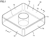
- Fig. 1 is a perspective view illustrating an example of the cutting tool
- Fig. 2 is a cross-sectional view along line X-X as seen in the direction indicated by the arrows in Fig. 1 .
- the cutting tool having such a shape is used as an indexable insert for turning.
- Cutting tool 10 shown in Figs. 1 and 2 has a surface including an upper surface, a lower surface, and four side surfaces.
- the overall shape of cutting tool 10 is a quadrangular prism of which top-to-bottom thickness is somewhat thin.
- a through hole extending through the upper and lower surfaces is formed.
- an arcuate surface connects a side surface to its adjacent side surface.
- the upper surface and the lower surface each form a rake face 1a
- the four side surfaces (and the arcuate surfaces connecting them) each form a flank face 1b
- the arcuate surface connecting rake face 1a to flank face 1b forms a cutting edge face 1c.
- Fig. 3 is a partially enlarged view of Fig. 2 .
- Fig. 3 shows an imaginary plane A including rake face 1a, an imaginary boundary line AA at which rake face 1a and imaginary plane A part from each other, an imaginary plane B including flank face 1b, and an imaginary boundary line BB at which flank face 1b and imaginary plane B part from each other .
- each imaginary plane A, B is shown as a line and each imaginary boundary line AA, BB is shown as a dot.
- the surface inside the region between imaginary boundary line AA and imaginary boundary line BB is cutting edge face 1c.
- cutting edge face 1c is generally a surface of base material 1.
- the ridgeline at which surfaces of base material 1 meet is machined to form cutting edge face 1c.
- base material 1 is formed by machining at least a part of the surface of a base material precursor formed of a sintered material or the like, and cutting edge face 1c is formed through beveling by means of machining.
- Figs. 1 to 3 show cutting edge face 1c which is an arcuate surface
- the shape of cutting edge face 1c is not limited to this.
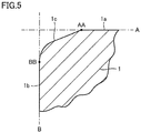
- cutting edge face 1c may have a flat shape.
- cutting edge face 1c may have a shape which is a combination of a flat surface and an arcuate surface.
- cutting edge face 1c can be determined easily from its shape only. This is for the reason: cutting edge face 1c in this case is included in none of imaginary plane A and imaginary plane B and can therefore be distinguished easily from rake face 1a and flank face 1b by visual inspection.
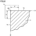
- cutting edge face 1c is defined herein as a surface included in a region within a distance d of 100 ⁇ m from a ridgeline AB at which rake face 1a and flank face 1b meet each other, since base material 1 included in this region is capable of functioning as a cutting edge of cutting tool 10.
- the base material of the present embodiment has an oxygen concentration of less than or equal to 1 at.% at a depth position of 0.4 ⁇ m from the cutting edge face.
- the oxygen concentration can be measured with an XPS analyzer applicable to XPS.
- XPS can be used to measure the ratio of atoms of a given kind at a given depth position in a target of measurement while etching the surface of the target by means of ions of Ar for example.
- XPS can be used to determine the oxygen concentration at a depth position of 0.4 ⁇ m from the cutting edge face which is a surface of the base material.
- the etching area at this time may be 500 to 50000 ⁇ m 2 .
- the oxygen concentration is measured under vacuum.
- the cutting edge face includes a cutting edge face on the rake face side and a cutting edge face on the flank face side.
- a depth position of 0.4 ⁇ m from the cutting edge face which is a surface of the base material means a position at a depth of 0.4 ⁇ m from one of the cutting edge faces and at a depth of more than or equal to 0.4 ⁇ m from the other cutting edge face.
- the surface of the base material is identified in the following way. First, in accordance with XPS, the cutting tool is etched from its topmost surface corresponding to the cutting edge face of the base material. Then, the depth position at which an element specific to the raw material for the base material (e.g. an element forming a binder phase in the base material) is measured is identified as a cutting edge face of the base material.
- an element specific to the raw material for the base material e.g. an element forming a binder phase in the base material
- the aforementioned oxygen concentration may be an average value. Specifically, given three measurement sites are determined on the cutting edge face of the base material, and the oxygen concentration is measured at a depth position of 0.4 ⁇ m from each of the measurement sites. The average of respective oxygen concentrations measured at these sites may be determined as the oxygen concentration.
- the inventors measured the oxygen concentration at a plurality of measurement sites of the cutting edge face to find that there is no significant difference between the value taken at each measurement site and the average value. Therefore, the oxygen concentration may be measured at a given single site of the cutting edge face and the value taken at this site may be determined as the oxygen concentration. If the measured oxygen concentration has an apparently abnormal value, however, such a value should be excluded.
- the single site is preferably determined in a central portion of the cutting edge face, since this portion contributes significantly to characteristics of the cutting tool and is therefore appropriate as a site for evaluating the characteristics of the cutting tool.
- the base material having an oxygen concentration of less than or equal to 1 at.% at a depth position of 0.4 ⁇ m from the cutting edge face can impart a high wear resistance and accordingly a long life to the cutting tool.
- the inventors suppose the reasons why the cutting tool of the present embodiment has a long time. Specifically, in the base material of the conventional cutting tool, unintended oxygen atoms are present in a region from the cutting edge face inward to a certain depth position. In a region in which the oxygen atoms are present at a high concentration that may influence the physical properties of the base material (also referred to as "high oxygen region”), the base material embrittles. Thus, cracks generated in the cutting edge face are likely to extend in the high oxygen region extending from the cutting edge face inward (in the depth direction of the base material).
- the width of the high oxygen region (the depth extending straight inward of the base material from the cutting edge face) is relatively large. As a result, a large (long) crack is formed. Hard particles included in the high oxygen region and hard particles mostly located in the high oxygen region are likely to drop off.
- the base material has an oxygen concentration of less than or equal to 1 at.% at a depth position of 0.4 ⁇ m from the cutting edge face, and the width of the high oxygen region is smaller than that of the conventional cutting tool or the base material does not have a high oxygen region. Therefore, 1) the region in which brittlement may occur is smaller than the conventional cutting tool or there is no such a region, which provides higher hardness than the conventional cutting tool, and 2) even when an origin of a crack is generated, extension of the crack is reduced as compared with the conventional cutting tool.
- the width of the high oxygen region is likely to be smaller than the particle size of hard particles located in the surface of the base material. Therefore, even when cracks extend across the entire high oxygen region, the length of the cracks is likely to be smaller than the particle size of hard particles located in the topmost surface of the base material, and eventually drop-off of hard particles is suppressed.
- the cutting tool of the present embodiment can therefore have a high wear resistance and a high fracture resistance and hence a long life.
- the base material preferably has an oxygen concentration of less than or equal to 10 at.% at a depth position of 0.2 ⁇ m from the cutting edge face.
- the oxygen concentration at a depth position of 0.4 ⁇ m from the cutting edge face and the oxygen concentration at a depth position of 0.2 ⁇ m from the cutting edge face are preferably 0 at.%
- the base material preferably has a strain of less than or equal to 0.07 in the cutting edge face.
- the strain in the cutting edge face can be determined by applying x-ray diffractometry. High-brightness x-ray like radioactive ray is preferable in that high-precision measurement is possible. As is apparent, however, a common x-ray apparatus may be used.
- ⁇ size and ⁇ strain are expressed by the following expression (2) and expression (3) where ⁇ is wavelength of x-ray, ⁇ is crystallite size, ⁇ is incident angle of x-ray, ⁇ is strain (non-uniform lattice strain), and ⁇ 0 is Bragg angle. Further, the following expressions (2) and (3) are substituted into the above expression (1) to obtain the following expression (4).
- the above-described strain may be an average value. Specifically, respective diffraction profiles (multiple diffraction profiles that are different in incident angle) are obtained at given three measurement sites in the cutting edge face of the base material, and the ⁇ value at each measurement site is calculated. The average of respective ⁇ values is determined as the strain.
- the measurement sites are located in a region of the base material at a thickness in the depth direction of 1.5 ⁇ m from the cutting edge face of the base material. Specifically, the strain is measured at each measurement site as an integral value of the strain of the base material in the region from the cutting edge face to the 1.5 ⁇ m depth.
- the inventors also calculated respective ⁇ values at multiple measurement sites of the cutting edge face to confirm that there is no significant difference between each value and the average value. Therefore, the strain may be measured at a given single site of the cutting edge face and the value taken at this site may be determined as the strain. If the measured strain has an apparently abnormal value, however, such a value should be excluded.
- the single site is preferably determined in a central portion of the cutting edge face, since this portion contributes significantly to characteristics of the cutting tool and is therefore appropriate as a site for evaluating the characteristics of the cutting tool.
- a sufficiently small strain of "less than or equal to 0.07" enables a still longer life of the cutting tool. This is for the reason that the small strain at such a site improves the peeling resistance of a coating formed on the base material as described below.
- the strain is more preferably less than or equal to 0.05. In this case, a still further longer life of the cutting tool is possible. Theoretically, it is most preferable that the strain is 0.
- the cutting tool of the present embodiment may further include a coating formed on the base material.
- a coating acts to improve various characteristics of the cutting tool such as wear resistance and toughness, by covering the surface of the base material.
- the cutting tool of the present embodiment is particularly excellent in adhesiveness between the base material and the coating, and can therefore suppress shortening of the tool life due to peeling of the coating. Therefore, the cutting tool of the present embodiment further including the coating can improve not only the wear resistance of the cutting tool itself but also the adhesiveness between the base material and the coating so as to enable a significantly longer life of the cutting tool.
- the reasons for the high adhesiveness between the base material and the coating in the cutting tool of the present embodiment are supposed to be as follows. If the oxygen concentration in the base material is high, the hardness of the base material may be low and/or the structure of the base material may be non-uniform. With such deterioration of the base material, the adhesiveness between the base material and the coating tends to be decreased. In contrast, in the cutting tool of the present embodiment, the width of the high oxygen region is relatively small as described above, and therefore, the oxygen concentration in the vicinity of the cutting edge face is lower than the conventional cutting tool. The foregoing is seen from the findings (a) to (c) described above. Thus, in the cutting tool of the present embodiment, deterioration of the base material is suppressed and consequently the adhesiveness between the base material and the coating is improved.
- the coating may be a physical vapor deposition layer formed by the physical vapor deposition (PVD) method, or a chemical vapor deposition layer formed by the chemical vapor deposition (CVD) method.
- the physical vapor deposition layer is usually formed on a base material having undergone etching by ions.
- the chemical vapor deposition layer is usually formed on a base material having undergone no etching. If the aforementioned coating is a chemical vapor deposition layer formed by the chemical vapor deposition method, the advantageous effects of the present embodiment are further enhanced.
- the physical vapor deposition layer and the chemical vapor deposition layer are clearly distinguished from each other through SEM observation of respective surfaces of these layers.
- the coating has a thickness of preferably 0.3 to 15 ⁇ m.
- the coating having a thickness of more than or equal to 0.3 ⁇ m can sufficiently exhibit the characteristics of the coating.
- the coating can have a thickness of less than or equal to 15 ⁇ m to suppress peel-off of the coating due to an excessively large coating thickness.
- the thickness of the coating is determined in the following way. First, a sample for measurement including a cross section parallel to the normal direction to the surface of the base material is prepared. Next, the cross section is observed with a scanning transmission electron microscope (STEM), and the magnification is adjusted so that the whole thickness-direction region of the coating is included in an observed image. Respective thicknesses at five or more points are measured and the average value of the measured thicknesses is determined as the thickness.
- STEM scanning transmission electron microscope
- the coating may be a single layer structure made up of a single layer, or a multilayer structure in which two or more layers are stacked together.
- the coating may be formed on either a part (e.g. cutting edge face) or the whole of the surface of the base material.
- the layer may be a compound layer made from: at least one kind of first element selected from the group consisting of Group IV elements (Ti, Zr, Hf), Group V elements (V, Nb, Ta), and Group VI elements (Cr, Mo, W) in the periodic table, Al, and Si; and at least one kind of second element selected from the group consisting of B, C, N, and O.
- first element selected from the group consisting of Group IV elements (Ti, Zr, Hf), Group V elements (V, Nb, Ta), and Group VI elements (Cr, Mo, W) in the periodic table, Al, and Si
- second element selected from the group consisting of B, C, N, and O.
- the compound layer may be TiCNO layer, TiBN layer, TiC layer, TiN layer, TiAlN layer, TiSiN layer, AlCrN layer, AlCrON layer, AlCrO layer, TiAlSiN layer, TiAlON layer, AlCrSiCN layer, TiCN layer, TiSiC layer, CrSiN layer, AlTiSiCO layer, TiSiCN layer, ZrO 2 layer, Al 2 O 3 layer, and the like.
- Layers containing Ti (TiCN layer, TiN layer, for example) are preferable for their particularly excellent hardness.
- Layers containing Al (Al 2 O 3 layer for example) are preferable for their particularly excellent oxidation resistance.
- a coating having a multilayer structure made up of a TiN layer, a TiCN layer, and an Al 2 O 3 layer stacked in this order from the base material side is preferable.
- Such a multilayer structure can significantly improve the wear resistance, the oxidation resistance, the heat-resistant stability, and the chipping resistance of the cutting tool by a synergistic effect of the layers.
- a method for manufacturing a cutting tool of the present embodiment includes the step of preparing a base material precursor and the step of producing a base material by machining a surface of the base material precursor. In the following, each step is described in detail.
- a base material precursor is prepared.
- the base material precursor may be a cemented carbide or a cermet as described above.
- the base material precursor is machined into "base material.” Specifically, the surface of the base material precursor is machined as detailed later herein to thereby form a cutting edge face.
- the shape of the base material precursor is therefore similar to the shape of the base material except that the base material precursor does not yet have a cutting edge face.
- a surface of the base material precursor is machined.
- the machining is one of a first grinding process of alternately repeating wet grinding and dry grinding, a second grinding process of performing low-feed low-depth-of-cut wet grinding, or a third grinding process of performing dry grinding.
- the base material of the cutting tool is produced.
- the cutting tool is completed through this step.
- the surface of the base material precursor to be machined is a ridgeline vicinity portion including a ridgeline at which a first surface and a second surface of the base material precursor meet, and a vicinity of the ridgeline.
- the first surface and the second surface of the base material precursor are respective portions that are to form a rake face and a flank face of the base material, and the ridgeline vicinity portion of the base material precursor is a portion that is to form a cutting edge face of the base material.
- the ridgeline vicinity portion machined in an arcuate shape forms a cutting edge face as shown in Fig. 3
- the ridgeline vicinity portion machined in a flat shape forms a cutting edge face as shown in Fig. 4 .
- the machining is beveling of the ridgeline vicinity portion of the base material precursor.
- Examples of the wet grinding (a process using water for grinding) in the first grinding process may include wet brushing, wet barrel finishing, and wet blasting. Conditions for this wet grinding are not particularly limited.
- the wet grinding may be either high-feed high-depth-of-cut grinding or low-feed low-depth-of-cut grinding.
- dry grinding (a process using no water for grinding) in the first grinding process may include dry brushing, dry barrel finishing, and dry blasting. Conditions for this dry grinding are not particularly limited.
- the dry grinding may be either high-feed high-depth-of-cut grinding or low-feed low-depth-of-cut grinding.
- the reasons why the first grinding process enables manufacture of the aforementioned cutting tool with a low oxygen concentration are as follows.
- the high-feed high-depth-of-cut wet grinding is performed for the conventional machining of the base material precursor into the base material.
- a first reason for this is a high productivity of the high-feed high-depth-of-cut wet grinding.
- a second reason for this is that the dry grinding has been considered as causing oxidation of the base material surface due to heat generated during the grinding.
- a third reason for this is that the productivity of the low-feed low-depth-of-cut wet grinding has been considered as low.
- this high-feed high-depth-of-cut wet grinding causes oxygen to enter from the cutting edge face toward the inside of the base material, resulting in decrease of the hardness of the base material itself and/or decrease of the adhesiveness between the base material and a coating.
- the machining in which wet grinding and dry grinding are repeated is performed, instead of the conventional machining in which high-feed high-depth-of-cut wet grinding is performed.
- Such machining of the present embodiment provides the treated surface (cutting edge face) with the following.
- a single wet grinding process is performed to bevel the base material precursor while oxygen enters from the surface of the base material precursor.
- the time taken to perform this wet grinding can be shortened as compared with the conventional process. Therefore, the width of a high oxygen region after the single wet grinding process is smaller than the conventional process.
- the dry grinding subsequent to the wet grinding does not cause oxygen to enter into the base material precursor. Therefore, the dry grinding is performed to bevel the base material precursor while removing the high oxygen region formed during the preceding wet grinding.
- the width of the high oxygen region is smaller than the conventional process, or there is no high oxygen region which may influence the physical properties of the base material. Accordingly, the aforementioned base material having an oxygen concentration of less than or equal to 1 at.% at a depth position of 0.4 ⁇ m from the cutting edge face is produced.
- each of the wet grinding and the dry grinding is performed at least once.
- the wet grinding and the dry grinding are alternately repeated three or more times. In this way, the width of the high oxygen region formed in each wet grinding process can further be reduced. Accordingly, the final high oxygen region width can also further be reduced. The oxygen concentration itself in the high oxygen region can also be reduced.
- the initial process in the machining process is the wet grinding and the final process therein is the dry grinding.
- the wet grinding as the initial process can improve the productivity and the dry grinding as the final process can control the high oxygen region width so that the high oxygen region width is sufficiently small in the finally obtained base material.
- Examples of the low-feed low-depth-of-cut wet grinding in the second grinding process may include wet brushing, wet barrel finishing, and wet blasting, like the first grinding process.
- the second grinding process suppresses entering of oxygen into the base material which is caused by the conventional high-feed high-depth-of-cut wet grinding, and therefore enables manufacture of the aforementioned cutting tool having a low oxygen concentration.
- low-feed low-depth-of-cut for wet grinding varies depending on the type of grinding
- low-feed low-depth-of-cut for wet brushing for example herein means that the feed is 200 mm/sec or less and the depth of cut is 1.5 mm or less.
- High-feed high-depth-of-cut for wet grinding which is wet brushing for example herein means that the feed is 300 mm/sec or more and the depth of cut is 3 mm or more.
- the wet grinding in the second grinding process is preferably performed at certain intervals, rather than continuously. Specifically, preferably a process in which the wet grinding is performed for a given time, subsequently stopped for a given time, and subsequently performed for a given time and so on is repeated. In this way, the advantageous effect of suppressing entering of oxygen can be improved.
- Examples of the dry grinding in the third grinding process may include dry brushing, dry barrel finishing, and dry blasting, like the first grinding process. Conditions for this dry grinding in the third grinding process are not particularly limited.
- the dry grinding may be either high-feed high-depth-of-cut grinding or low-feed low-depth-of-cut grinding.
- the third grinding process suppresses entering of oxygen into the base material which is caused by the conventional high-feed high-depth-of-cut wet grinding, and therefore enables manufacture of the aforementioned cutting tool having a low oxygen concentration.
- the first grinding process, the second grinding process, and the third grinding process are as described above.
- the machining is preferably the first grinding process.
- the cutting tool having a low oxygen concentration can be manufactured while keeping a high productivity.
- the method for manufacturing a cutting tool in the present embodiment may further include the step of forming a coating on a surface of the base material. Accordingly, a cutting tool with a coating formed on the surface of the base material can be manufactured.
- a physical vapor deposition (PVD) or chemical vapor deposition (CVD) method may be used as a method for forming the coating.
- the CVD method is preferably used.
- the film deposition temperature is 800 to 1200°C. This temperature is higher than that of the physical vapor deposition method.
- the CVD method thus increases the adhesiveness between the base material and the coating.
- a conventionally known method may be used as the CVD method.
- the aforementioned cutting tool including the base material having an oxygen concentration of less than or equal to 1 at.% at a depth position of 0.4 ⁇ m from the cutting edge face can be manufactured.
- This cutting tool has a long life.
- the strain in the cutting edge face of the base material can be controlled to be small by adjusting conditions for the machining.
- surface treatment of the coating may be performed as required, by any of various methods like brushing, or blasting such as sand blasting, wet blasting, shot peening, or bombardment for PVD, for example. Accordingly, a compressive stress can be imparted to the coating.
- Non-coated cutting tools of Sample Nos. 1A, 1B, 1C, 1D, 1a, and 1b were produced, and characteristics of them were evaluated.
- Sample Nos. 1A to 1D are Examples and Sample Nos. 1a and 1b are Comparative Examples.
- the cutting tool of Sample No. 1A (indexable insert) was produced in the following way.
- the cutting tool is formed of a base material with the following specifications.
- raw material powder made up of a mixture having a composition: 2.0 mass% TaC, 1.0 mass% NbC, 6 mass% Co, and the balance WC (containing inevitable impurities) was press-formed in a predetermined shape, and thereafter sintered at 1300 to 1500°C for 1 to 2 hours. Accordingly, a base material precursor was obtained.
- barrel finishing media plastic process liquid: water time: 5 minutes
- the cutting tool of Sample No. 1B was produced similarly to Sample No. 1A except that the below-described low-feed low-depth-of-cut wet grinding, i.e., second grinding process, was performed as the machining of the base material precursor.
- barrel finishing media plastic process liquid: water time: 3 minutes
- the cutting tool of Sample No. 1C was produced similarly to Sample No. 1A except that the below-described dry grinding, i.e., third grinding process, was performed as the machining of the base material precursor.
- the cutting tool of Sample No. 1D (indexable insert) was produced in the following way.
- This cutting tool is formed of a base material with the following specifications.
- raw material powder made up of a mixture having a composition: 7 mass% NbC, 7 mass% Mo 2 C, 10 mass% Co, 5 mass% Ni, 20 mass% WC, and the balance TiCN (containing inevitable impurities) was press-formed in a predetermined shape, and thereafter sintered at 1300 to 1650°C for 1 to 2 hours. Accordingly, a base material precursor was obtained.
- the cutting tool of Sample No. 1a was produced similarly to Sample No. 1A except that the below-described high-feed high-depth-of-cut wet grinding was performed without performing the above-described dry grinding, as the machining of the base material precursor.
- barrel finishing media plastic process liquid: water time: 3 minutes
- the cutting tool of Sample No. 1b was produced similarly to Sample No. 1D except that the wet grinding similar to Sample No. 1a was performed without performing the above-described dry grinding, as the machining of the base material precursor.
- the oxygen concentration at a depth position of 0.4 ⁇ m from the cutting edge face, the oxygen concentration at a depth position of 0.2 ⁇ m from the cutting edge face, and strain in the cutting edge face were each measured in the way as described above.
- XPS analyzer for measurement of oxygen concentration
- JPS-9030 manufactured by JEOL Ltd.
- x-ray apparatus for measurement of strain
- SPring 8 Japan Synchrotron Radiation Research Institute: JASRI Conditions for the radiation (high brightness x-ray) of SPring-8 used for measurement of strain by x-ray diffractometry are as follows.
- beam line BL16XU incident x-ray energy: 10.012 keV (wavelength ⁇ : 1.2385 angstrom) scanning range: 20° to 120° at 2 ⁇ [Table 1] sample base material 0.4 oxygen concentration (at.%) 0.2 oxygen concentration (at.%) strain Test 1 Vb (mm) Test 2 Vb (mm) No.
- the column “0.4 oxygen concentration (at.%)” indicates the oxygen concentration at a depth position of 0.4 ⁇ m from the cutting edge face
- the column “0.2 oxygen concentration (at.%)” indicates the oxygen concentration at a depth position of 0.2 ⁇ m from the cutting edge face.
- the values of oxygen concentrations and strain are each an average value of measurements taken at three measurement sites.
- Coated cutting tools of Sample Nos. 2A, 2B, 2C, 2D, 2E, 2F, 2G, 2H, 21, 2J, 2K, 2L, 2a, 2b, 2c, 2d, and 2e were produced, and characteristics of them were evaluated.
- Sample Nos. 2A to 2L are Examples and Sample Nos. 2a to 2e are Comparative Examples.
- Respective base materials for Sample Nos. 2A to 2K were each produced in the following way. First, a base material precursor made of a cemented carbide was produced similarly to Sample No. 1A. Next, machining was performed on the base material precursor similarly to Sample No. 1A except that the process time and the number of repetition times of each of the above-described wet grinding and dry grinding were changed appropriately for the machining of the base material precursor. In this way, respective base materials for Sample Nos. 2A to 2K were produced.
- the base material for Sample No. 2L was produced in the following way. First, a base material precursor made of a cermet was produced similarly to Sample No. 1D. Next, machining was performed on the base material precursor similarly to Sample No. 1D except that the process time and the number of repetition times of each of the above-described wet grinding and dry grinding were changed appropriately. In this way, the base material for Sample No. 2L was produced.
- Respective base materials for Sample Nos. 2a to 2e were each produced in the following way. First, a base material precursor made of a cemented carbide was produced similarly to Sample No. 1A. Next, machining was performed on the base material precursor similarly to Sample No. 1A except that the below-described high-feed high-depth-of-cut wet grinding was performed without performing the above-described dry grinding. In this way, respective base materials for Sample Nos. 2a to 2e were produced.
- barrel finishing media plastic process liquid: water time: 3 minutes
- a CVD apparatus was used to form a coating shown in Table 2 on the entire surface of each base material by the MT-CVD method.
- base material/TiN(0.4)/TiCN(6.5)/Al 2 O 3 (3.5)/TiN(0.7) indicates that a coating was formed in which a TiN layer, a TiCN layer, an Al 2 O 3 layer, and a TiN layer were stacked in this order from the surface of the base material.
- the thickness ( ⁇ m) of the layer is indicated.
- the MT-CVD method is a method for depositing a layer under a relatively mild temperature environment of 850 to 950°C. [Table 2] sample coating No.
- blasting was performed on the entire surface of the coating formed on the surface of each base material.
- balls made of aluminum oxide having an average particle size of 50 ⁇ m were forced to impinge uniformly against the rake face, the flank face, and the cutting edge face for 5 seconds by means of compressed air (projection pressure) at 0.10 MPa, in the direction at 45° with respect to an imaginary ridgeline formed by an imaginary plane including the rake face and an imaginary plane including the flank face, while the base material was rotated at 100 rpm.
- the projection pressure and the process time were changed appropriately to obtain respective cutting tools of Sample Nos. 2A to 2L and 2a to 2e.
- the oxygen concentration at a depth position of 0.4 ⁇ m from the cutting edge face, the oxygen concentration at a depth position of 0.2 ⁇ m from the cutting edge face, and the strain in the cutting edge face were each measured in the way as described above.
- the column “0.4 oxygen concentration (at.%)” indicates the oxygen concentration at a depth position of 0.4 ⁇ m from the cutting edge face
- the column “0.2 oxygen concentration (at.%)” indicates the oxygen concentration at a depth position of 0.2 ⁇ m from the cutting edge face.
- the values of oxygen concentrations and strain are each an average of measurements taken at three measurement sites.
Landscapes
- Engineering & Computer Science (AREA)
- Mechanical Engineering (AREA)
- Chemical & Material Sciences (AREA)
- Organic Chemistry (AREA)
- Materials Engineering (AREA)
- Metallurgy (AREA)
- Chemical Kinetics & Catalysis (AREA)
- Manufacturing & Machinery (AREA)
- Chemical Vapour Deposition (AREA)
- Cutting Tools, Boring Holders, And Turrets (AREA)
- Drilling Tools (AREA)
- Milling, Broaching, Filing, Reaming, And Others (AREA)
- Finish Polishing, Edge Sharpening, And Grinding By Specific Grinding Devices (AREA)
Abstract
Description
- The present invention relates to a cutting tool and a method for manufacturing the cutting tool. The present application claims priority to Japanese Patent Application No.
2016-164780 filed on August 25, 2016 - With the aim of extending the life of the cutting tool, various studies have been conducted. For example, Japanese Patent Laying-Open Nos.
5-237707 2013-244549 -
- PTL 1: Japanese Patent Laying-Open No.
5-237707 - PTL 2: Japanese Patent Laying-Open No.
2013-244549 - A cutting tool according to an aspect of the present disclosure is a cutting tool including a base material. The base material is a cemented carbide or a cermet. A surface of the base material includes a rake face, a flank face, and a cutting edge face connecting the rake face to the flank face. The base material has an oxygen concentration of less than or equal to 1 at.% at a depth position of 0.4 µm from the cutting edge face.
- A method for manufacturing a cutting tool according to an aspect of the present disclosure is a method for manufacturing the above-described cutting tool. The method includes: preparing a base material precursor; and producing a base material by machining a surface of the base material precursor. The machining is one of: a first grinding process of alternately repeating wet grinding and dry grinding; a second grinding process of performing low-feed low-depth-of-cut wet grinding; or a third grinding process of performing dry grinding.
-
-
Fig. 1 is a perspective view illustrating an example of a cutting tool. -
Fig. 2 is a cross-sectional view along line X-X as seen in the direction indicated by arrows inFig. 1 . -
Fig. 3 is partially enlarged view ofFig. 2 . -
Fig. 4 illustrates a different shape of a cutting edge face. -
Fig. 5 illustrates another different shape of the cutting edge face. -
Fig. 6 illustrates still another different shape of the cutting edge face. - For the cutting tool having the coating as described above, it is necessary to address the problem that the coating may peel off (i.e. tool fracture) due to lack of adhesion between the coating and the base material. For example, according to
PTL 1, WC and Co which are components of the base material can be prevented from being diffused into the coating so as to produce a stable adhesion. According to PTL 2, the defect density in the surface of the base material can be controlled to produce a stable adhesion. - A variety of different demands are imposed on the cutting tool. For example, there may be a demand for a cutting tool without coating (also referred to as "non-coated cutting tool") for the sake of lower cost and the like. Moreover, the severity of demands on a cutting tool with a coating (also referred to as "coated cutting tool") is increasing. Under the circumstances, every type of cutting tools is generally required to have a longer life.
- In view of the above, an object of the present disclosure is to provide a cutting tool having an extended life as well as a method for manufacturing the cutting tool.
- According to the foregoing, a cutting tool having an extended life and a method for manufacturing the cutting tool are provided.
- First of all, the present invention is described based on features listed below. The expression "A to B" as used herein is intended to define an upper limit and a lower limit of a certain range (i.e., from A to B inclusive). As to "A to B" where A is not followed by a unit symbol and only B is followed by a unit symbol, the unit of A is the same as the unit of B.
- [1] A cutting tool according to an aspect of the present disclosure is a cutting tool including a base material. The base material is a cemented carbide or a cermet. A surface of the base material includes a rake face, a flank face, and a cutting edge face connecting the rake face to the flank face. The base material has an oxygen concentration of less than or equal to 1 at.% at a depth position of 0.4 µm from the cutting edge face. Such a cutting tool is excellent in wear resistance and fracture resistance and can therefore have a long life.
- [2] The base material of the cutting tool has an oxygen concentration of less than or equal to 10 at.% at a depth position of 0.2 µm from the cutting edge face. Accordingly, the cutting tool can have a still longer life.
- [3] The cutting edge face of the base material of the cutting tool has a strain of less than or equal to 0.07. Accordingly, the cutting tool can have a still longer life.
- [4] The cutting tool further includes a coating formed on the base material. Accordingly, the cutting tool has enhanced characteristics of the cutting tool.
- [5] The coating of the cutting tool includes a compound layer made from: at least one kind of first element selected from the group consisting of Group IV elements, Group V elements, and Group VI elements in the periodic table, Al, and Si; and at least one kind of second element selected from the group consisting of B, C, N, and O. Such a coating can improve the characteristics of the cutting tool.
- [6] A method for manufacturing a cutting tool according to an aspect of the present disclosure is a method for manufacturing the above-described cutting tool. The method includes: preparing a base material precursor; and producing a base material by machining a surface of the base material precursor. The machining is one of: a first grinding process of alternately repeating wet grinding and dry grinding; a second grinding process of performing low-feed low-depth-of-cut wet grinding; or a third grinding process of performing dry grinding. Accordingly, the cutting tool having a long life can be manufactured.
- [7] The method for manufacturing further includes forming a coating on a surface of the base material. Accordingly, the cutting tool having the coating can be manufactured.
- The inventors of the present invention first conducted a wear resistance test on a variety of coated cutting tools, and observed cross sections of the tested coated cutting tools with a scanning electron microscope (SEM). As a result of the observation, not only peeling of the coating but also depth-direction extension of cracks from the cutting edge face of the base material and dropping off of hard particles originally contained in the base material were confirmed. In order to find the cause of these phenomena, the inventors performed atomic-level observation rather than the conventional nano-level observation.
- Specifically, they used x-ray photoelectron spectroscopy (XPS) to observe coated cutting tools before and after the wear resistance test, checked the results of the observation against the results of the wear resistance test, and further conducted studies. They found that unintended oxygen atoms had entered the base material of the coated cutting tool and the presence of the oxygen atoms was involved in the above phenomena.
- The coated cutting tool is produced through a process in a relatively severe environment. Specifically, the coating is formed on the surface of the base material by chemical vapor deposition or the like. It was therefore originally assumed that the step of forming a coating on the base material supplied oxygen atoms into the base material. However, studies of the non-coated cutting tool revealed that oxygen atoms also entered the base material of the non-coated cutting tool. The above assumption was thus disproved.
- The inventors then focused on machining performed on a base material precursor. "Base material precursor" is a material machined into "base material" by beveling of the surface of the base material precursor to form a cutting edge. In other words, this machining is a process performed on a base material precursor such as a sintered material, so that the base material precursor assumes properties of the base material for the cutting tool. For machining a hard base material precursor, high-feed high-depth-of-cut wet grinding is performed industrially in order to suppress heat generation during the machining or to improve the machining quality. The inventors found that water used for this wet grinding was a source of the oxygen atoms.
- Subsequently, the inventors conducted further studies on the difference in the manner in which oxygen atoms enter the base material, depending on the difference in the machining method. The inventors employed a machining method different from conventional methods to succeed in improving the wear resistance of both the coated cutting tool and the non-coated cutting tool. The present invention has been made in this way.
- An embodiment (hereinafter referred to as "present embodiment") of the present invention is described in the following. The present embodiment, however, is not limited to those described herein. In the drawings used for the following description of the embodiment, the same reference characters denote the same parts or corresponding parts. A compound or the like expressed herein by a chemical formula includes the compound with any of all conventionally known atomic ratios if the atomic ratio is not particularly limited, and the compound is not necessarily limited to the compound with a stoichiometric ratio. For example, regarding an expression "TiCN," the ratio of the number of atoms between the elements constituting TiCN is not limited to Ti:C:N = 1:0.5:0.5, but includes all conventionally known atomic ratios.
- A cutting tool of the present embodiment includes a base material. The shape and the use for example of the cutting tool are not particularly limited. The cutting tool of the present embodiment may for example be drill, end mill, indexable insert for the drill, indexable insert for the end mill, indexable insert for milling, indexable insert for turning, metal-slitting saw, gear-cutting tool, reamer, tap, or the like.
- The base material is a cemented carbide or a cermet. The cemented carbide may be a WC-based cemented carbide (also including a cemented carbide containing WC and Co, or alternatively a cemented carbide containing WC and Co and additionally a carbonitride of Ti, Ta, Nb or the like). The cermet may be a cermet containing TiC, TiN, TiCN or the like as a main component. In particular, the cermet is preferably a TiCN-based cermet.
- The base material has a surface. The surface includes a rake face, a flank face, and a cutting edge face connecting the rake face to the flank face. The cutting edge face is a surface forming a cutting edge of the cutting tool. Which region of the base material is to form a cutting edge face is determined depending on the shape of the base material, as described below with reference to
Figs. 1 to 3 . -
Fig. 1 is a perspective view illustrating an example of the cutting tool, andFig. 2 is a cross-sectional view along line X-X as seen in the direction indicated by the arrows inFig. 1 . The cutting tool having such a shape is used as an indexable insert for turning. - Cutting
tool 10 shown inFigs. 1 and2 has a surface including an upper surface, a lower surface, and four side surfaces. The overall shape of cuttingtool 10 is a quadrangular prism of which top-to-bottom thickness is somewhat thin. In cuttingtool 10, a through hole extending through the upper and lower surfaces is formed. Along each of the boundaries of the four side surfaces, an arcuate surface connects a side surface to its adjacent side surface. - As to cutting
tool 10, the upper surface and the lower surface each form arake face 1a, the four side surfaces (and the arcuate surfaces connecting them) each form aflank face 1b, and the arcuate surface connectingrake face 1a to flank face 1b forms acutting edge face 1c. -
Fig. 3 is a partially enlarged view ofFig. 2 .Fig. 3 shows an imaginary plane A includingrake face 1a, an imaginary boundary line AA at which rakeface 1a and imaginary plane A part from each other, an imaginary plane B includingflank face 1b, and an imaginary boundary line BB at which flank face 1b and imaginary plane B part from each other . InFig. 3 , each imaginary plane A, B is shown as a line and each imaginary boundary line AA, BB is shown as a dot. InFig. 3 , the surface inside the region between imaginary boundary line AA and imaginary boundary line BB is cuttingedge face 1c. - Thus, cutting
edge face 1c is generally a surface ofbase material 1. The ridgeline at which surfaces ofbase material 1 meet is machined to form cuttingedge face 1c. In other words,base material 1 is formed by machining at least a part of the surface of a base material precursor formed of a sintered material or the like, and cuttingedge face 1c is formed through beveling by means of machining. - While
Figs. 1 to 3 show cuttingedge face 1c which is an arcuate surface, the shape of cuttingedge face 1c is not limited to this. For example, as shown inFig. 4 , cuttingedge face 1c may have a flat shape. Further, as shown inFig. 5 , cuttingedge face 1c may have a shape which is a combination of a flat surface and an arcuate surface. - Regarding
base materials 1 having respective shapes as shown inFigs. 3 to 5 as described above, cuttingedge face 1c can be determined easily from its shape only. This is for the reason: cuttingedge face 1c in this case is included in none of imaginary plane A and imaginary plane B and can therefore be distinguished easily fromrake face 1a andflank face 1b by visual inspection. - Regarding
base material 1 having a sharp edge shape as shown inFig. 6 , it is difficult to determine cuttingedge face 1c formed by machining, from its shape only. This is for the reason: cuttingedge face 1c in this case is included in imaginary plane A and/or imaginary plane B and it is therefore difficult to distinguish cuttingedge face 1c fromrake face 1a andflank face 1b by visual inspection. - In view of the above, regarding
base material 1 having a sharp edge shape, cuttingedge face 1c is defined herein as a surface included in a region within a distance d of 100 µm from a ridgeline AB at which rakeface 1a andflank face 1b meet each other, sincebase material 1 included in this region is capable of functioning as a cutting edge of cuttingtool 10. - The base material of the present embodiment has an oxygen concentration of less than or equal to 1 at.% at a depth position of 0.4 µm from the cutting edge face. The oxygen concentration can be measured with an XPS analyzer applicable to XPS.
- XPS can be used to measure the ratio of atoms of a given kind at a given depth position in a target of measurement while etching the surface of the target by means of ions of Ar for example. Thus, XPS can be used to determine the oxygen concentration at a depth position of 0.4 µm from the cutting edge face which is a surface of the base material. The etching area at this time may be 500 to 50000 µm2. The oxygen concentration is measured under vacuum.
- Regarding the cutting edge face having a sharp edge shape, the cutting edge face includes a cutting edge face on the rake face side and a cutting edge face on the flank face side. In this case, "a depth position of 0.4 µm from the cutting edge face which is a surface of the base material" means a position at a depth of 0.4 µm from one of the cutting edge faces and at a depth of more than or equal to 0.4 µm from the other cutting edge face.
- For a cutting tool in which the surface of the base material does not form the topmost surface of the cutting tool, such as a cutting tool having another member such as coating on the surface of the base material, for example, the surface of the base material is identified in the following way. First, in accordance with XPS, the cutting tool is etched from its topmost surface corresponding to the cutting edge face of the base material. Then, the depth position at which an element specific to the raw material for the base material (e.g. an element forming a binder phase in the base material) is measured is identified as a cutting edge face of the base material.
- The aforementioned oxygen concentration may be an average value. Specifically, given three measurement sites are determined on the cutting edge face of the base material, and the oxygen concentration is measured at a depth position of 0.4 µm from each of the measurement sites. The average of respective oxygen concentrations measured at these sites may be determined as the oxygen concentration.
- The inventors measured the oxygen concentration at a plurality of measurement sites of the cutting edge face to find that there is no significant difference between the value taken at each measurement site and the average value. Therefore, the oxygen concentration may be measured at a given single site of the cutting edge face and the value taken at this site may be determined as the oxygen concentration. If the measured oxygen concentration has an apparently abnormal value, however, such a value should be excluded. The single site is preferably determined in a central portion of the cutting edge face, since this portion contributes significantly to characteristics of the cutting tool and is therefore appropriate as a site for evaluating the characteristics of the cutting tool.
- Regarding the cutting tool of the present embodiment, the base material having an oxygen concentration of less than or equal to 1 at.% at a depth position of 0.4 µm from the cutting edge face can impart a high wear resistance and accordingly a long life to the cutting tool.
- The inventors have found the following (a) to (c) by studies regarding the present disclosure:
- (a) in the cutting edge face of the base material for the cutting tool, unintended oxygen atoms have entered, and the oxygen concentration derived from the oxygen atoms is highest in the vicinity of the cutting edge face and decreases gradually toward the inside of the base material;
- (b) the higher the oxygen concentration in the vicinity of the cutting edge face, the deeper the locations of oxygen in the base material;
- (c) in the base material in which oxygen atoms enter at a deep depth from the cutting edge face, cracks are likely to extend inward from the cutting edge face, and hard particles forming the base material are likely to drop off.
- Based on the above findings, the inventors suppose the reasons why the cutting tool of the present embodiment has a long time. Specifically, in the base material of the conventional cutting tool, unintended oxygen atoms are present in a region from the cutting edge face inward to a certain depth position. In a region in which the oxygen atoms are present at a high concentration that may influence the physical properties of the base material (also referred to as "high oxygen region"), the base material embrittles. Thus, cracks generated in the cutting edge face are likely to extend in the high oxygen region extending from the cutting edge face inward (in the depth direction of the base material).
- Particularly in the conventional cutting tool, the width of the high oxygen region (the depth extending straight inward of the base material from the cutting edge face) is relatively large. As a result, a large (long) crack is formed. Hard particles included in the high oxygen region and hard particles mostly located in the high oxygen region are likely to drop off.
- In contrast, in the cutting tool of the present embodiment, the base material has an oxygen concentration of less than or equal to 1 at.% at a depth position of 0.4 µm from the cutting edge face, and the width of the high oxygen region is smaller than that of the conventional cutting tool or the base material does not have a high oxygen region. Therefore, 1) the region in which brittlement may occur is smaller than the conventional cutting tool or there is no such a region, which provides higher hardness than the conventional cutting tool, and 2) even when an origin of a crack is generated, extension of the crack is reduced as compared with the conventional cutting tool.
- In particular, when the oxygen concentration at a depth position of 0.4 µm is less than or equal to 1 at.%, the width of the high oxygen region is likely to be smaller than the particle size of hard particles located in the surface of the base material. Therefore, even when cracks extend across the entire high oxygen region, the length of the cracks is likely to be smaller than the particle size of hard particles located in the topmost surface of the base material, and eventually drop-off of hard particles is suppressed. The cutting tool of the present embodiment can therefore have a high wear resistance and a high fracture resistance and hence a long life.
- Regarding the cutting tool of the present embodiment, the base material preferably has an oxygen concentration of less than or equal to 10 at.% at a depth position of 0.2 µm from the cutting edge face. In this case, extension of cracks can further be suppressed and drop-off of hard particles can further be suppressed, and therefore, a still longer life of the cutting tool is possible. Theoretically the oxygen concentration at a depth position of 0.4 µm from the cutting edge face and the oxygen concentration at a depth position of 0.2 µm from the cutting edge face are preferably 0 at.%
- Regarding the cutting tool of the present embodiment, the base material preferably has a strain of less than or equal to 0.07 in the cutting edge face. The strain in the cutting edge face can be determined by applying x-ray diffractometry. High-brightness x-ray like radioactive ray is preferable in that high-precision measurement is possible. As is apparent, however, a common x-ray apparatus may be used.
- Regarding a diffraction profile of x-ray diffraction angle (2θ) and diffraction intensity obtained by x-ray diffractometry, it is known that the diffraction peak expands (broadens) depending on each of crystallite size and strain. Each of the diffraction peak depending on crystallite size and the diffraction peak depending on strain can be approximated by a Lorentz function to express the integral breadth β of the diffraction peak by the following expression (1), where βsize is the integral breadth of the diffraction profile depending on crystallite size, and βstrain is the integral breadth of the diffraction profile depending on strain.

- βsize and βstrain are expressed by the following expression (2) and expression (3) where λ is wavelength of x-ray, ε is crystallite size, θ is incident angle of x-ray, η is strain (non-uniform lattice strain), and θ0 is Bragg angle. Further, the following expressions (2) and (3) are substituted into the above expression (1) to obtain the following expression (4).



- On a two-axis graph with the vertical axis representing βcosθ0/λ and the horizontal axis representing sinθ0/λ, values determined from multiple diffraction profiles with different 2θ values are plotted, and the plots are linearly regressed. The slope of the obtained regression line is strain (non-uniform lattice strain) and the reciprocal of the segment of the regression line is crystallite size.
- The above-described strain may be an average value. Specifically, respective diffraction profiles (multiple diffraction profiles that are different in incident angle) are obtained at given three measurement sites in the cutting edge face of the base material, and the η value at each measurement site is calculated. The average of respective η values is determined as the strain. The measurement sites are located in a region of the base material at a thickness in the depth direction of 1.5 µm from the cutting edge face of the base material. Specifically, the strain is measured at each measurement site as an integral value of the strain of the base material in the region from the cutting edge face to the 1.5 µm depth.
- The inventors also calculated respective η values at multiple measurement sites of the cutting edge face to confirm that there is no significant difference between each value and the average value. Therefore, the strain may be measured at a given single site of the cutting edge face and the value taken at this site may be determined as the strain. If the measured strain has an apparently abnormal value, however, such a value should be excluded. The single site is preferably determined in a central portion of the cutting edge face, since this portion contributes significantly to characteristics of the cutting tool and is therefore appropriate as a site for evaluating the characteristics of the cutting tool.
- A sufficiently small strain of "less than or equal to 0.07" enables a still longer life of the cutting tool. This is for the reason that the small strain at such a site improves the peeling resistance of a coating formed on the base material as described below. The strain is more preferably less than or equal to 0.05. In this case, a still further longer life of the cutting tool is possible. Theoretically, it is most preferable that the strain is 0.
- The cutting tool of the present embodiment may further include a coating formed on the base material. Such a coating acts to improve various characteristics of the cutting tool such as wear resistance and toughness, by covering the surface of the base material. The cutting tool of the present embodiment is particularly excellent in adhesiveness between the base material and the coating, and can therefore suppress shortening of the tool life due to peeling of the coating. Therefore, the cutting tool of the present embodiment further including the coating can improve not only the wear resistance of the cutting tool itself but also the adhesiveness between the base material and the coating so as to enable a significantly longer life of the cutting tool.
- The reasons for the high adhesiveness between the base material and the coating in the cutting tool of the present embodiment are supposed to be as follows. If the oxygen concentration in the base material is high, the hardness of the base material may be low and/or the structure of the base material may be non-uniform. With such deterioration of the base material, the adhesiveness between the base material and the coating tends to be decreased. In contrast, in the cutting tool of the present embodiment, the width of the high oxygen region is relatively small as described above, and therefore, the oxygen concentration in the vicinity of the cutting edge face is lower than the conventional cutting tool. The foregoing is seen from the findings (a) to (c) described above. Thus, in the cutting tool of the present embodiment, deterioration of the base material is suppressed and consequently the adhesiveness between the base material and the coating is improved.
- The coating may be a physical vapor deposition layer formed by the physical vapor deposition (PVD) method, or a chemical vapor deposition layer formed by the chemical vapor deposition (CVD) method. The physical vapor deposition layer is usually formed on a base material having undergone etching by ions. In contrast, the chemical vapor deposition layer is usually formed on a base material having undergone no etching. If the aforementioned coating is a chemical vapor deposition layer formed by the chemical vapor deposition method, the advantageous effects of the present embodiment are further enhanced. The physical vapor deposition layer and the chemical vapor deposition layer are clearly distinguished from each other through SEM observation of respective surfaces of these layers.
- The coating has a thickness of preferably 0.3 to 15 µm. The coating having a thickness of more than or equal to 0.3 µm can sufficiently exhibit the characteristics of the coating. The coating can have a thickness of less than or equal to 15 µm to suppress peel-off of the coating due to an excessively large coating thickness.
- The thickness of the coating is determined in the following way. First, a sample for measurement including a cross section parallel to the normal direction to the surface of the base material is prepared. Next, the cross section is observed with a scanning transmission electron microscope (STEM), and the magnification is adjusted so that the whole thickness-direction region of the coating is included in an observed image. Respective thicknesses at five or more points are measured and the average value of the measured thicknesses is determined as the thickness.
- The coating may be a single layer structure made up of a single layer, or a multilayer structure in which two or more layers are stacked together. The coating may be formed on either a part (e.g. cutting edge face) or the whole of the surface of the base material.
- The layer may be a compound layer made from: at least one kind of first element selected from the group consisting of Group IV elements (Ti, Zr, Hf), Group V elements (V, Nb, Ta), and Group VI elements (Cr, Mo, W) in the periodic table, Al, and Si; and at least one kind of second element selected from the group consisting of B, C, N, and O. Such a compound layer is suitable as a coating of the cutting tool.
- Specific examples of the compound layer may be TiCNO layer, TiBN layer, TiC layer, TiN layer, TiAlN layer, TiSiN layer, AlCrN layer, AlCrON layer, AlCrO layer, TiAlSiN layer, TiAlON layer, AlCrSiCN layer, TiCN layer, TiSiC layer, CrSiN layer, AlTiSiCO layer, TiSiCN layer, ZrO2 layer, Al2O3 layer, and the like. Layers containing Ti (TiCN layer, TiN layer, for example) are preferable for their particularly excellent hardness. Layers containing Al (Al2O3 layer for example) are preferable for their particularly excellent oxidation resistance.
- Among others, a coating having a multilayer structure made up of a TiN layer, a TiCN layer, and an Al2O3 layer stacked in this order from the base material side is preferable. Such a multilayer structure can significantly improve the wear resistance, the oxidation resistance, the heat-resistant stability, and the chipping resistance of the cutting tool by a synergistic effect of the layers.
- A method for manufacturing a cutting tool of the present embodiment includes the step of preparing a base material precursor and the step of producing a base material by machining a surface of the base material precursor. In the following, each step is described in detail.
- In this step, a base material precursor is prepared. The base material precursor may be a cemented carbide or a cermet as described above. The base material precursor is machined into "base material." Specifically, the surface of the base material precursor is machined as detailed later herein to thereby form a cutting edge face. The shape of the base material precursor is therefore similar to the shape of the base material except that the base material precursor does not yet have a cutting edge face.
- In this step, a surface of the base material precursor is machined. The machining is one of a first grinding process of alternately repeating wet grinding and dry grinding, a second grinding process of performing low-feed low-depth-of-cut wet grinding, or a third grinding process of performing dry grinding. In this way, the base material of the cutting tool is produced. For a cutting tool made up of the base material only, the cutting tool is completed through this step.
- The surface of the base material precursor to be machined is a ridgeline vicinity portion including a ridgeline at which a first surface and a second surface of the base material precursor meet, and a vicinity of the ridgeline. The first surface and the second surface of the base material precursor are respective portions that are to form a rake face and a flank face of the base material, and the ridgeline vicinity portion of the base material precursor is a portion that is to form a cutting edge face of the base material.
- For example, the ridgeline vicinity portion machined in an arcuate shape forms a cutting edge face as shown in
Fig. 3 , and the ridgeline vicinity portion machined in a flat shape forms a cutting edge face as shown inFig. 4 . Specifically, the machining is beveling of the ridgeline vicinity portion of the base material precursor. - Examples of the wet grinding (a process using water for grinding) in the first grinding process may include wet brushing, wet barrel finishing, and wet blasting. Conditions for this wet grinding are not particularly limited. For example, the wet grinding may be either high-feed high-depth-of-cut grinding or low-feed low-depth-of-cut grinding.
- Examples of the dry grinding (a process using no water for grinding) in the first grinding process may include dry brushing, dry barrel finishing, and dry blasting. Conditions for this dry grinding are not particularly limited. For example, the dry grinding may be either high-feed high-depth-of-cut grinding or low-feed low-depth-of-cut grinding.
- The reasons why the first grinding process enables manufacture of the aforementioned cutting tool with a low oxygen concentration are as follows. For the conventional machining of the base material precursor into the base material, the high-feed high-depth-of-cut wet grinding is performed. A first reason for this is a high productivity of the high-feed high-depth-of-cut wet grinding. A second reason for this is that the dry grinding has been considered as causing oxidation of the base material surface due to heat generated during the grinding. A third reason for this is that the productivity of the low-feed low-depth-of-cut wet grinding has been considered as low.
- However, this high-feed high-depth-of-cut wet grinding causes oxygen to enter from the cutting edge face toward the inside of the base material, resulting in decrease of the hardness of the base material itself and/or decrease of the adhesiveness between the base material and a coating.
- In contrast, according to the method for manufacturing in the present embodiment, the machining in which wet grinding and dry grinding are repeated is performed, instead of the conventional machining in which high-feed high-depth-of-cut wet grinding is performed. Such machining of the present embodiment provides the treated surface (cutting edge face) with the following.
- A single wet grinding process is performed to bevel the base material precursor while oxygen enters from the surface of the base material precursor. The time taken to perform this wet grinding can be shortened as compared with the conventional process. Therefore, the width of a high oxygen region after the single wet grinding process is smaller than the conventional process. Further, the dry grinding subsequent to the wet grinding does not cause oxygen to enter into the base material precursor. Therefore, the dry grinding is performed to bevel the base material precursor while removing the high oxygen region formed during the preceding wet grinding.
- Thus, consequently the width of the high oxygen region is smaller than the conventional process, or there is no high oxygen region which may influence the physical properties of the base material. Accordingly, the aforementioned base material having an oxygen concentration of less than or equal to 1 at.% at a depth position of 0.4 µm from the cutting edge face is produced.
- Although the number of times the wet grinding and the dry grinding are repeated is not particularly limited, each of the wet grinding and the dry grinding is performed at least once. Preferably, the wet grinding and the dry grinding are alternately repeated three or more times. In this way, the width of the high oxygen region formed in each wet grinding process can further be reduced. Accordingly, the final high oxygen region width can also further be reduced. The oxygen concentration itself in the high oxygen region can also be reduced.
- Preferably, the initial process in the machining process is the wet grinding and the final process therein is the dry grinding. The wet grinding as the initial process can improve the productivity and the dry grinding as the final process can control the high oxygen region width so that the high oxygen region width is sufficiently small in the finally obtained base material.
- Examples of the low-feed low-depth-of-cut wet grinding in the second grinding process may include wet brushing, wet barrel finishing, and wet blasting, like the first grinding process. The second grinding process suppresses entering of oxygen into the base material which is caused by the conventional high-feed high-depth-of-cut wet grinding, and therefore enables manufacture of the aforementioned cutting tool having a low oxygen concentration.
- While "low-feed low-depth-of-cut" for wet grinding varies depending on the type of grinding, "low-feed low-depth-of-cut" for wet brushing for example herein means that the feed is 200 mm/sec or less and the depth of cut is 1.5 mm or less. "High-feed high-depth-of-cut" for wet grinding which is wet brushing for example herein means that the feed is 300 mm/sec or more and the depth of cut is 3 mm or more.
- The wet grinding in the second grinding process is preferably performed at certain intervals, rather than continuously. Specifically, preferably a process in which the wet grinding is performed for a given time, subsequently stopped for a given time, and subsequently performed for a given time and so on is repeated. In this way, the advantageous effect of suppressing entering of oxygen can be improved.
- Examples of the dry grinding in the third grinding process may include dry brushing, dry barrel finishing, and dry blasting, like the first grinding process. Conditions for this dry grinding in the third grinding process are not particularly limited. For example, the dry grinding may be either high-feed high-depth-of-cut grinding or low-feed low-depth-of-cut grinding. The third grinding process suppresses entering of oxygen into the base material which is caused by the conventional high-feed high-depth-of-cut wet grinding, and therefore enables manufacture of the aforementioned cutting tool having a low oxygen concentration.
- The first grinding process, the second grinding process, and the third grinding process are as described above. The machining is preferably the first grinding process. In this case, the cutting tool having a low oxygen concentration can be manufactured while keeping a high productivity.
- The method for manufacturing a cutting tool in the present embodiment may further include the step of forming a coating on a surface of the base material. Accordingly, a cutting tool with a coating formed on the surface of the base material can be manufactured.
- As a method for forming the coating, a physical vapor deposition (PVD) or chemical vapor deposition (CVD) method may be used. In the present embodiment, the CVD method is preferably used. When the CVD method is used, the film deposition temperature is 800 to 1200°C. This temperature is higher than that of the physical vapor deposition method. The CVD method thus increases the adhesiveness between the base material and the coating. A conventionally known method may be used as the CVD method.
- In this way, the aforementioned cutting tool including the base material having an oxygen concentration of less than or equal to 1 at.% at a depth position of 0.4 µm from the cutting edge face can be manufactured. This cutting tool has a long life.
- The strain in the cutting edge face of the base material can be controlled to be small by adjusting conditions for the machining.
- After the coating is formed, surface treatment of the coating may be performed as required, by any of various methods like brushing, or blasting such as sand blasting, wet blasting, shot peening, or bombardment for PVD, for example. Accordingly, a compressive stress can be imparted to the coating.
- In the following, the present invention is described in further detail with reference to Examples. The present invention, however, is not limited to them.
- Non-coated cutting tools of Sample Nos. 1A, 1B, 1C, 1D, 1a, and 1b were produced, and characteristics of them were evaluated. Sample Nos. 1A to 1D are Examples and Sample Nos. 1a and 1b are Comparative Examples.
- The cutting tool of Sample No. 1A (indexable insert) was produced in the following way. The cutting tool is formed of a base material with the following specifications.
- Insert Model No.: CNMG120408N-UX (manufactured by Sumitomo Electric Hardmetal)
Material: cemented carbide specified by JIS B4120 (2013) - First, raw material powder made up of a mixture having a composition: 2.0 mass% TaC, 1.0 mass% NbC, 6 mass% Co, and the balance WC (containing inevitable impurities) was press-formed in a predetermined shape, and thereafter sintered at 1300 to 1500°C for 1 to 2 hours. Accordingly, a base material precursor was obtained.
- Next, on a ridgeline vicinity portion of the base material precursor, the below-described wet grinding and dry grinding were alternately repeated in this order five times, i.e., the first grinding process was performed. Accordingly, the ridgeline vicinity portion of the base material precursor was machined so that an arcuate cutting edge face with R = 0.03 mm was formed. In this way, the base material for Sample No. 1A, i.e., the cutting tool of Sample No. 1A was produced.
- type: barrel finishing
media: plastic
process liquid: water
time: 5 minutes - type: brushing
brush: nylon
rotational speed: 100 rpm
depth of cut: 1.5 mm
feed: 150 mm/sec
process liquid: none
time: 1 minute
paste: diamond paste with an average particle size of 10 µm or less (liquid component contained in the paste is solid oil) - The cutting tool of Sample No. 1B was produced similarly to Sample No. 1A except that the below-described low-feed low-depth-of-cut wet grinding, i.e., second grinding process, was performed as the machining of the base material precursor.
- type: barrel finishing
media: plastic
process liquid: water
time: 3 minutes - The cutting tool of Sample No. 1C was produced similarly to Sample No. 1A except that the below-described dry grinding, i.e., third grinding process, was performed as the machining of the base material precursor.
- type: brushing
brush: nylon
rotational speed: 100 rpm
depth of cut: 1.5 mm
feed: 150 mm/sec
process liquid: none
time: 1 minute
paste: diamond paste with an average particle size of 10 µm or less (liquid component contained in the paste is solid oil) - The cutting tool of Sample No. 1D (indexable insert) was produced in the following way. This cutting tool is formed of a base material with the following specifications.
- Insert Model No.: CNMG120408N-UX (manufactured by Sumitomo Electric Hardmetal)
Material: cermet of grade P20 - First, raw material powder made up of a mixture having a composition: 7 mass% NbC, 7 mass% Mo2C, 10 mass% Co, 5 mass% Ni, 20 mass% WC, and the balance TiCN (containing inevitable impurities) was press-formed in a predetermined shape, and thereafter sintered at 1300 to 1650°C for 1 to 2 hours. Accordingly, a base material precursor was obtained.
- Next, on a ridgeline vicinity portion of the base material precursor, machining was performed similarly to Sample No. 1A except that the process time and the number of repetition times of each of the above-described wet grinding and dry grinding were changed. Accordingly, the ridgeline vicinity portion of the base material precursor was machined so that an arcuate cutting edge face with R = 0.03 mm was formed. In this way, the cutting tool of Sample No. 1D was produced.
- The cutting tool of Sample No. 1a was produced similarly to Sample No. 1A except that the below-described high-feed high-depth-of-cut wet grinding was performed without performing the above-described dry grinding, as the machining of the base material precursor.
- type: barrel finishing
media: plastic
process liquid: water
time: 3 minutes - The cutting tool of Sample No. 1b was produced similarly to Sample No. 1D except that the wet grinding similar to Sample No. 1a was performed without performing the above-described dry grinding, as the machining of the base material precursor.
- For each cutting tool, the oxygen concentration at a depth position of 0.4 µm from the cutting edge face, the oxygen concentration at a depth position of 0.2 µm from the cutting edge face, and strain in the cutting edge face were each measured in the way as described above.
- The oxygen concentrations and the strain were each measured at given three measurement sites of the cutting edge face (surface having undergone honing with R = 0.3 mm). One of the three measurement sites was a central portion of the cutting edge face. The results are shown in Table 2.
- The following apparatuses were used.
XPS analyzer (for measurement of oxygen concentration): "JPS-9030" manufactured by JEOL Ltd.
x-ray apparatus (for measurement of strain): "SPring 8," Japan Synchrotron Radiation Research Institute: JASRI
Conditions for the radiation (high brightness x-ray) of SPring-8 used for measurement of strain by x-ray diffractometry are as follows.
beam line: BL16XU
incident x-ray energy: 10.012 keV (wavelength λ: 1.2385 angstrom)
scanning range: 20° to 120° at 2θ[Table 1] sample base material 0.4 oxygen concentration (at.%) 0.2 oxygen concentration (at.%) strain Test 1 Vb (mm) Test 2 Vb (mm) No. 1A cemented carbide 0.8 6.3 0.03 1.75 2.05 No. 1B cemented carbide 0.8 7.5 0.04 1.82 2.12 No. 1C cemented carbide 0.7 8.2 0.03 1.92 1.95 No. ID cermet 0.7 8.5 0.03 1.65 1.82 No. 1a cemented carbide 1.2 10.5 0.15 4.82 4.96 No. 1b cermet 1.5 11.2 0.10 fracture fracture - In Table 1, the column "0.4 oxygen concentration (at.%)" indicates the oxygen concentration at a depth position of 0.4 µm from the cutting edge face, and the column "0.2 oxygen concentration (at.%)" indicates the oxygen concentration at a depth position of 0.2 µm from the cutting edge face. The values of oxygen concentrations and strain are each an average value of measurements taken at three measurement sites.
- With each cutting tool, cutting was performed under the following cutting conditions. The average wear amount Vb (mm) of the flank face after a cutting time of 20 minutes was measured. The results are shown in Table 1. For this test, a low-alloy steel undergoes low-speed cutting, and therefore, the workpiece to be cut is likely to adhere to the cutting tool. When the component adhering to the cutting tool drops off, hard particles are likely to drop off, and consequently the wear amount increases. In view of this, this test can be performed to evaluate the fracture resistance of the cutting tool. Specifically, the smaller the value of Vb (mm), the higher the fracture resistance. In the Table, "fracture" means that the cutting edge was significantly fractured and the wear amount was therefore unmeasurable.
- workpiece: SCM415
cutting speed: 100 m/min
feed: 0.2 mm/rev
depth of cut: 2.0 mm
cutting liquid: water-soluble cutting oil - With each cutting tool, cutting was performed under the following cutting conditions. The average wear amount Vb (mm) of the flank face after a cutting time of 15 minutes was measured. The results are shown in Table 1. The smaller the value of Vb (mm), the higher the wear resistance. In the Table, "fracture" means that the cutting edge was significantly fractured and the wear amount was therefore unmeasurable.
- workpiece: FCD700
cutting speed: 200 m/min
feed: 0.2 mm/rev
depth of cut: 2.0 mm
cutting liquid: water-soluble cutting oil - As shown in Table 1, the cutting tools of Sample Nos. 1A to 1D exhibited higher fracture resistance and higher wear resistance as compared with the cutting tools of Sample Nos. 1a and 1b. It was thus confirmed that the cutting tools of the Examples were longer in life than the cutting tools of the Comparative Examples.
- Coated cutting tools of Sample Nos. 2A, 2B, 2C, 2D, 2E, 2F, 2G, 2H, 21, 2J, 2K, 2L, 2a, 2b, 2c, 2d, and 2e were produced, and characteristics of them were evaluated. Sample Nos. 2A to 2L are Examples and Sample Nos. 2a to 2e are Comparative Examples.
- Respective base materials for Sample Nos. 2A to 2K were each produced in the following way. First, a base material precursor made of a cemented carbide was produced similarly to Sample No. 1A. Next, machining was performed on the base material precursor similarly to Sample No. 1A except that the process time and the number of repetition times of each of the above-described wet grinding and dry grinding were changed appropriately for the machining of the base material precursor. In this way, respective base materials for Sample Nos. 2A to 2K were produced.
- The base material for Sample No. 2L was produced in the following way. First, a base material precursor made of a cermet was produced similarly to Sample No. 1D. Next, machining was performed on the base material precursor similarly to Sample No. 1D except that the process time and the number of repetition times of each of the above-described wet grinding and dry grinding were changed appropriately. In this way, the base material for Sample No. 2L was produced.
- Respective base materials for Sample Nos. 2a to 2e were each produced in the following way. First, a base material precursor made of a cemented carbide was produced similarly to Sample No. 1A. Next, machining was performed on the base material precursor similarly to Sample No. 1A except that the below-described high-feed high-depth-of-cut wet grinding was performed without performing the above-described dry grinding. In this way, respective base materials for Sample Nos. 2a to 2e were produced.
- type: barrel finishing
media: plastic
process liquid: water
time: 3 minutes - Next, a CVD apparatus was used to form a coating shown in Table 2 on the entire surface of each base material by the MT-CVD method. For example, "base material/TiN(0.4)/TiCN(6.5)/Al2O3(3.5)/TiN(0.7)" of No. 2A indicates that a coating was formed in which a TiN layer, a TiCN layer, an Al2O3 layer, and a TiN layer were stacked in this order from the surface of the base material. In the parentheses following the composition of each layer, the thickness (µm) of the layer is indicated. The MT-CVD method is a method for depositing a layer under a relatively mild temperature environment of 850 to 950°C.
[Table 2] sample coating No. 2A base material / TiN (0.4) / TiCN (6.5) /Al2O3 (3.5) / TiN (0.5) No. 2B base material / TiN (0.4) / TiCN (8.3) /Al2O3 (5.5) / TiN (0. 5) No. 2C base material / TiN (0.4) / TiCN (4.5) /TiAlN (3.0) No. 2D base material / TiN (0.4) / TiAlN (5.5) No. 2E base material / TiN (0.4) /TiAlSiN (3.5) / AlCrN (3.5) No. 2F base material / TiN (0.4) / TiCN (6.5) /Al2O3 (3.5) / TiN (0. 5) No. 2G base material / TiN (0.4) / TiCN (4.0) /Al2O3 (2.5) / TiN (0.5) No. 2H base material / TiN (0.4) / TiCN (5.0) /Al2O3 (4.5) / TiN (0.5) No. 21 base material / TiN (0.4) / TiCN (6.5) /Al2O3 (3.5) / TiN (0. 5) No. 2J base material / TiN (0.4) / TiCN (8.3) /Al2O3 (5.5) / TiN (0. 5) No. 2K base material / TiN (0.4) / TiCN (4.5) /TiAlN (3.0) No. 2L base material / TiN (0.4) / TiCN (5.0) No. 2a base material / TiN (0.4) / TiCN (6.5) /Al2O3 (3.5) / TiN (0. 5) No. 2b base material / TiN (0.4) / TiCN (6.5) /Al2O3 (3.5) / TiN (0. 5) No. 2c base material / TiN (0.4) / TiCN (8.3) /Al2O3 (5.5) / TiN (0. 5) No. 2d base material / TiN (0.4) / TiCN (4.5) /TiAlN (3.0) No. 2e base material / TiN (0.4) / TiCN (5.0) - Next, blasting was performed on the entire surface of the coating formed on the surface of each base material. For example, for the base material for No. 2A, balls made of aluminum oxide having an average particle size of 50 µm were forced to impinge uniformly against the rake face, the flank face, and the cutting edge face for 5 seconds by means of compressed air (projection pressure) at 0.10 MPa, in the direction at 45° with respect to an imaginary ridgeline formed by an imaginary plane including the rake face and an imaginary plane including the flank face, while the base material was rotated at 100 rpm. For the base materials for Nos. 2B to 2L and 2a to 2e, the projection pressure and the process time were changed appropriately to obtain respective cutting tools of Sample Nos. 2A to 2L and 2a to 2e.
- For each cutting tool, the oxygen concentration at a depth position of 0.4 µm from the cutting edge face, the oxygen concentration at a depth position of 0.2 µm from the cutting edge face, and the strain in the cutting edge face were each measured in the way as described above.
- The oxygen concentrations and the strain were each measured at given three measurement sites of the cutting edge face. One of the three measurement sites was a central portion of the cutting edge face. The results are shown in Table 3. The apparatuses used for measuring the values were similar to those described above.
[Table 3] sample base material 0.4 oxygen concentration (at.%) 0.2 oxygen concentration (at.%) strain Test 3 Vb (mm) Test 4 Vb (mm) No. 2A cemented carbide 0.8 8.5 0.02 0.07 0.12 No. 2B cemented carbide 0.8 6.3 0.03 0.04 0.09 No. 2C cemented carbide 0.9 9.2 0.02 0.05 0.11 No. 2D cemented carbide 0.7 5.3 0.06 0.06 0.08 No. 2E cemented carbide 0.8 8.8 0.04 0.05 0.12 No. 2F cemented carbide 0.9 5.4 0.09 0.12 0.18 No. 2G cemented carbide 0.7 9.2 0.12 0.11 0.17 No. 2H cemented carbide 0.8 8.3 0.15 0.09 0.18 No. 2I cemented carbide 0.7 13.5 0.09 0.15 0.21 No. 2J cemented carbide 0.8 15.2 0.11 0.14 0.22 No. 2K cemented carbide 0.7 11.3 0.14 0.16 0.21 No. 2L cermet 0.7 4.2 0.03 0.04 0.09 No. 2a cemented carbide 1.2 13.2 0.08 3.25 3.89 No. 2b cemented carbide 1.3 14.2 0.32 2.85 3.46 No. 2c cemented carbide 2.4 15.6 0.21 2.36 3.65 No. 2d cemented carbide 1.2 12.1 0.12 3.49 3.35 No. 2e cemented carbide 1.4 14.3 0.32 2.43 3.74 - In Table 3, the column "0.4 oxygen concentration (at.%)" indicates the oxygen concentration at a depth position of 0.4 µm from the cutting edge face, and the column "0.2 oxygen concentration (at.%)" indicates the oxygen concentration at a depth position of 0.2 µm from the cutting edge face. The values of oxygen concentrations and strain are each an average of measurements taken at three measurement sites.
- With each cutting tool, cutting was performed under the following cutting conditions. The average wear amount Vb (mm) of the flank face after a cutting time of 20 minutes was measured. The results are shown in Table 3. For this test, a low-alloy steel undergoes low-speed cutting, and therefore, the workpiece to be cut is likely to adhere to the cutting tool. When the component adhering to the cutting tool drops off, hard particles are likely to drop off, and consequently the wear amount increases. In view of this, this test can be performed to evaluate the fracture resistance of the cutting tool. Specifically, the smaller the value of Vb (mm), the higher the fracture resistance.
- workpiece: SCM415
cutting speed: 100 m/min
feed: 0.2 mm/rev
depth of cut: 2.0 mm
cutting liquid: water-soluble cutting oil - With each cutting tool, cutting was performed under the following cutting conditions. The average wear amount Vb (mm) of the flank face after a cutting time of 15 minutes was measured. The results are shown in Table 3. The smaller the value of Vb (mm), the higher the wear resistance.
- workpiece: FCD700
cutting speed: 200 m/min
feed: 0.2 mm/rev
depth of cut: 2.0 mm
cutting liquid: water-soluble cutting oil - As shown in Table 3, the cutting tools of Sample Nos. 2A to 2L exhibited higher fracture resistance and higher wear resistance as compared with the cutting tools of Sample Nos. 2a to 2e. It was thus confirmed that the cutting tools of the Examples were longer in life than the cutting tools of the Comparative Examples.
- The embodiments and Examples of the present invention are those as described above. It is originally intended that features of the above-described embodiments and Examples may be combined as appropriate.
- It should be construed that the embodiments and examples disclosed herein are given by way of illustration in all respects, not by way of limitation. It is intended that the scope of the present invention is defined by claims, not by the description above, and encompasses all modifications and variations equivalent in meaning and scope to the claims.
- 10 cutting tool; 1 base material; 1a rake face; 1b flank face; 1c cutting edge face
Claims (7)
- A cutting tool comprising a base material,
the base material being a cemented carbide or a cermet,
a surface of the base material including a rake face, a flank face, and a cutting edge face connecting the rake face to the flank face,
the base material having an oxygen concentration of less than or equal to 1 at.% at a depth position of 0.4 µm from the cutting edge face. - The cutting tool according to claim 1, wherein the base material has an oxygen concentration of less than or equal to 10 at.% at a depth position of 0.2 µm from the cutting edge face.
- The cutting tool according to claim 1 or 2, wherein the cutting edge face of the base material has a strain of less than or equal to 0.07.
- The cutting tool according to any one of claims 1 to 3, further comprising a coating formed on the base material.
- The cutting tool according to claim 4, wherein the coating includes a compound layer made from:at least one kind of first element selected from the group consisting of Group IV elements, Group V elements, and Group VI elements in the periodic table, Al, and Si; andat least one kind of second element selected from the group consisting of B, C, N, and O.
- A method for manufacturing a cutting tool according to any one of claims 1 to 5, the method comprising:preparing a base material precursor; andproducing a base material by machining a surface of the base material precursor,the machining being one ofa first grinding process of alternately repeating wet grinding and dry grinding;a second grinding process of performing low-feed low-depth-of-cut wet grinding, ora third grinding process of performing dry grinding.
- The method for manufacturing a cutting tool according to claim 6, further comprising forming a coating on a surface of the base material.
Applications Claiming Priority (2)
| Application Number | Priority Date | Filing Date | Title |
|---|---|---|---|
| JP2016164780A JP2018030205A (en) | 2016-08-25 | 2016-08-25 | Cutting tool and method for manufacturing the same |
| PCT/JP2017/019480 WO2018037647A1 (en) | 2016-08-25 | 2017-05-25 | Cutting tool and manufacturing method thereof |
Publications (3)
| Publication Number | Publication Date |
|---|---|
| EP3505280A1 true EP3505280A1 (en) | 2019-07-03 |
| EP3505280A4 EP3505280A4 (en) | 2020-05-06 |
| EP3505280B1 EP3505280B1 (en) | 2023-04-12 |
Family
ID=61246697
Family Applications (1)
| Application Number | Title | Priority Date | Filing Date |
|---|---|---|---|
| EP17843135.9A Active EP3505280B1 (en) | 2016-08-25 | 2017-05-25 | Cutting tool and method for manufacturing the same |
Country Status (6)
| Country | Link |
|---|---|
| US (1) | US11020805B2 (en) |
| EP (1) | EP3505280B1 (en) |
| JP (1) | JP2018030205A (en) |
| KR (1) | KR20190032454A (en) |
| CN (1) | CN109641284A (en) |
| WO (1) | WO2018037647A1 (en) |
Families Citing this family (2)
| Publication number | Priority date | Publication date | Assignee | Title |
|---|---|---|---|---|
| CN109023294A (en) * | 2018-09-18 | 2018-12-18 | 陕西航天时代导航设备有限公司 | A kind of diamond coatings slotting cutter and its manufacturing process |
| CN116174784A (en) * | 2023-04-18 | 2023-05-30 | 江西洪都航空工业集团有限责任公司 | Numerical control processing method for alloy steel material |
Family Cites Families (24)
| Publication number | Priority date | Publication date | Assignee | Title |
|---|---|---|---|---|
| JP3118857B2 (en) * | 1991-03-22 | 2000-12-18 | 三菱マテリアル株式会社 | High-strength tungsten carbide-based cemented carbide cutting tool and method of manufacturing the same |
| JPH0598384A (en) * | 1991-10-08 | 1993-04-20 | Mitsubishi Materials Corp | Tungsten carbide based cemented carbide with high strength and hardness |
| JP2733809B2 (en) | 1992-02-26 | 1998-03-30 | 日立ツール株式会社 | Coated tool |
| JPH07223102A (en) * | 1994-02-14 | 1995-08-22 | Mitsubishi Materials Corp | Cermet made cutting tool having high chipping resistance |
| JPH0892685A (en) | 1994-09-27 | 1996-04-09 | Toshiba Tungaloy Co Ltd | High toughness coated sintered alloy |
| JP4019366B2 (en) * | 2002-05-01 | 2007-12-12 | 三菱マテリアル株式会社 | Surface-coated cemented carbide miniature drill with low deflection deformation during high-speed drilling |
| JP4077739B2 (en) * | 2003-02-18 | 2008-04-23 | 京セラ株式会社 | Surface-coated Ti-based cermet cutting tool and method for manufacturing the same |
| DE10332101B4 (en) * | 2003-07-15 | 2016-02-04 | Kennametal Inc. | Cutting tool and method for its production |
| WO2006009121A1 (en) * | 2004-07-23 | 2006-01-26 | Sumitomo Electric Hardmetal Corp. | Surface coating cutting tool with coating film having intensity distribution of compression stress |
| WO2006104004A1 (en) * | 2005-03-28 | 2006-10-05 | Kyocera Corporation | Super hard alloy and cutting tool |
| JP4783153B2 (en) * | 2006-01-06 | 2011-09-28 | 住友電工ハードメタル株式会社 | Replaceable cutting edge |
| JP4936761B2 (en) * | 2006-03-28 | 2012-05-23 | 京セラ株式会社 | Cutting tools |
| JP2008069420A (en) | 2006-09-15 | 2008-03-27 | Tungaloy Corp | Cemented carbide and coated cemented carbide, and manufacturing methods therefor |
| JP5084369B2 (en) * | 2007-06-27 | 2012-11-28 | 京セラ株式会社 | Cutting tools |
| US8668982B2 (en) * | 2009-11-10 | 2014-03-11 | Kennametal Inc. | Coated cutting insert and method for making the same |
| JP2012030309A (en) * | 2010-07-29 | 2012-02-16 | Kyocera Corp | Cutting tool and manufacturing method therefor |
| EP2638993B1 (en) * | 2010-11-10 | 2019-07-24 | Sumitomo Electric Hardmetal Corp. | Surface-coated cutting tool |
| JP5286625B2 (en) * | 2011-01-31 | 2013-09-11 | 住友電工ハードメタル株式会社 | Surface-coated cutting tool and manufacturing method thereof |
| JP2013107187A (en) * | 2011-11-24 | 2013-06-06 | Mitsubishi Materials Corp | Cutting tool made of surface-coated wc-based cemented carbide |
| JP3177984U (en) | 2012-02-17 | 2012-08-30 | 圭治 一瀬 | Polishing tool |
| EP2634285A1 (en) * | 2012-02-29 | 2013-09-04 | Sandvik Intellectual Property AB | Coated cutting tool |
| JP5858363B2 (en) | 2012-05-24 | 2016-02-10 | 住友電工ハードメタル株式会社 | Substrate for cutting tool and surface-coated cutting tool including the same |
| JP2015009327A (en) * | 2013-06-28 | 2015-01-19 | 京セラ株式会社 | Cutting insert |
| KR102126105B1 (en) | 2015-10-09 | 2020-06-23 | 스미또모 덴꼬오 하드메탈 가부시끼가이샤 | Surface-coated cutting tool and method of manufacturing the same |
-
2016
- 2016-08-25 JP JP2016164780A patent/JP2018030205A/en active Pending
-
2017
- 2017-05-25 EP EP17843135.9A patent/EP3505280B1/en active Active
- 2017-05-25 WO PCT/JP2017/019480 patent/WO2018037647A1/en not_active Ceased
- 2017-05-25 US US16/328,229 patent/US11020805B2/en active Active
- 2017-05-25 KR KR1020197004884A patent/KR20190032454A/en not_active Ceased
- 2017-05-25 CN CN201780052027.7A patent/CN109641284A/en active Pending
Also Published As
| Publication number | Publication date |
|---|---|
| CN109641284A (en) | 2019-04-16 |
| EP3505280B1 (en) | 2023-04-12 |
| JP2018030205A (en) | 2018-03-01 |
| EP3505280A4 (en) | 2020-05-06 |
| KR20190032454A (en) | 2019-03-27 |
| WO2018037647A1 (en) | 2018-03-01 |
| US20190210117A1 (en) | 2019-07-11 |
| US11020805B2 (en) | 2021-06-01 |
Similar Documents
| Publication | Publication Date | Title |
|---|---|---|
| EP3173169B1 (en) | Coated cutting tool | |
| US10456841B2 (en) | Surface-coated cutting tool in which hard coating layers exhibits excellent chipping resistance | |
| EP3342511A1 (en) | Coated surface cutting tool and manufacturing method therefor | |
| EP3549701A1 (en) | Surface-coated cutting tool | |
| CN108472739B (en) | Surface-coated cutting tools | |
| EP4494788B1 (en) | Cutting tool | |
| EP3769877A1 (en) | Surface-coated cutting tool | |
| EP3527309A1 (en) | Surface-coated cutting tool | |
| EP3162911A1 (en) | Laminated hard film and cutting tool | |
| EP3305446A1 (en) | Surface-coated cutting tool with rigid coating layer exhibiting excellent chipping resistance | |
| EP3505278B1 (en) | Surface coated cutting tool and manufacturing method thereof | |
| DE102015115859B4 (en) | Multi-layer structured coatings for cutting tools | |
| EP3505280B1 (en) | Cutting tool and method for manufacturing the same | |
| EP3505279B1 (en) | Surface-coated cutting tool and method for manufacturing the same | |
| EP3505281A1 (en) | Surface coated cutting tool and manufacturing method thereof | |
| US12350742B2 (en) | Surface-coated cutting tool | |
| JP2019119045A (en) | Surface-coated cutting tool having hard coating layer exerting excellent chipping resistance | |
| EP3318657A1 (en) | Coated cutting tool |
Legal Events
| Date | Code | Title | Description |
|---|---|---|---|
| STAA | Information on the status of an ep patent application or granted ep patent |
Free format text: STATUS: THE INTERNATIONAL PUBLICATION HAS BEEN MADE |
|
| PUAI | Public reference made under article 153(3) epc to a published international application that has entered the european phase |
Free format text: ORIGINAL CODE: 0009012 |
|
| STAA | Information on the status of an ep patent application or granted ep patent |
Free format text: STATUS: REQUEST FOR EXAMINATION WAS MADE |
|
| 17P | Request for examination filed |
Effective date: 20190207 |
|
| AK | Designated contracting states |
Kind code of ref document: A1 Designated state(s): AL AT BE BG CH CY CZ DE DK EE ES FI FR GB GR HR HU IE IS IT LI LT LU LV MC MK MT NL NO PL PT RO RS SE SI SK SM TR |
|
| AX | Request for extension of the european patent |
Extension state: BA ME |
|
| DAV | Request for validation of the european patent (deleted) | ||
| DAX | Request for extension of the european patent (deleted) | ||
| A4 | Supplementary search report drawn up and despatched |
Effective date: 20200403 |
|
| RIC1 | Information provided on ipc code assigned before grant |
Ipc: B23B 51/00 20060101ALI20200330BHEP Ipc: B24B 3/34 20060101ALI20200330BHEP Ipc: B23F 21/00 20060101ALI20200330BHEP Ipc: C23C 14/06 20060101ALI20200330BHEP Ipc: B23D 77/00 20060101ALI20200330BHEP Ipc: B23G 5/06 20060101ALI20200330BHEP Ipc: B23C 5/16 20060101ALI20200330BHEP Ipc: C22C 29/08 20060101ALI20200330BHEP Ipc: B23B 27/14 20060101AFI20200330BHEP |
|
| REG | Reference to a national code |
Ref country code: DE Ref legal event code: R079 Ref document number: 602017067714 Country of ref document: DE Free format text: PREVIOUS MAIN CLASS: B23B0027140000 Ipc: C23C0014060000 |
|
| RIC1 | Information provided on ipc code assigned before grant |
Ipc: C22C 29/04 20060101ALI20221005BHEP Ipc: B22F 5/10 20060101ALI20221005BHEP Ipc: B22F 3/24 20060101ALI20221005BHEP Ipc: C22C 29/08 20060101ALI20221005BHEP Ipc: C23C 14/06 20060101AFI20221005BHEP |
|
| GRAP | Despatch of communication of intention to grant a patent |
Free format text: ORIGINAL CODE: EPIDOSNIGR1 |
|
| STAA | Information on the status of an ep patent application or granted ep patent |
Free format text: STATUS: GRANT OF PATENT IS INTENDED |
|
| INTG | Intention to grant announced |
Effective date: 20221122 |
|
| GRAS | Grant fee paid |
Free format text: ORIGINAL CODE: EPIDOSNIGR3 |
|
| GRAA | (expected) grant |
Free format text: ORIGINAL CODE: 0009210 |
|
| STAA | Information on the status of an ep patent application or granted ep patent |
Free format text: STATUS: THE PATENT HAS BEEN GRANTED |
|
| AK | Designated contracting states |
Kind code of ref document: B1 Designated state(s): AL AT BE BG CH CY CZ DE DK EE ES FI FR GB GR HR HU IE IS IT LI LT LU LV MC MK MT NL NO PL PT RO RS SE SI SK SM TR |
|
| REG | Reference to a national code |
Ref country code: GB Ref legal event code: FG4D |
|
| REG | Reference to a national code |
Ref country code: CH Ref legal event code: EP |
|
| REG | Reference to a national code |
Ref country code: DE Ref legal event code: R096 Ref document number: 602017067714 Country of ref document: DE |
|
| REG | Reference to a national code |
Ref country code: IE Ref legal event code: FG4D |
|
| REG | Reference to a national code |
Ref country code: AT Ref legal event code: REF Ref document number: 1559834 Country of ref document: AT Kind code of ref document: T Effective date: 20230515 |
|
| REG | Reference to a national code |
Ref country code: SE Ref legal event code: TRGR |
|
| P01 | Opt-out of the competence of the unified patent court (upc) registered |
Effective date: 20230515 |
|
| REG | Reference to a national code |
Ref country code: LT Ref legal event code: MG9D |
|
| REG | Reference to a national code |
Ref country code: NL Ref legal event code: MP Effective date: 20230412 |
|
| REG | Reference to a national code |
Ref country code: AT Ref legal event code: MK05 Ref document number: 1559834 Country of ref document: AT Kind code of ref document: T Effective date: 20230412 |
|
| PG25 | Lapsed in a contracting state [announced via postgrant information from national office to epo] |
Ref country code: NL Free format text: LAPSE BECAUSE OF FAILURE TO SUBMIT A TRANSLATION OF THE DESCRIPTION OR TO PAY THE FEE WITHIN THE PRESCRIBED TIME-LIMIT Effective date: 20230412 |
|
| PG25 | Lapsed in a contracting state [announced via postgrant information from national office to epo] |
Ref country code: PT Free format text: LAPSE BECAUSE OF FAILURE TO SUBMIT A TRANSLATION OF THE DESCRIPTION OR TO PAY THE FEE WITHIN THE PRESCRIBED TIME-LIMIT Effective date: 20230814 Ref country code: NO Free format text: LAPSE BECAUSE OF FAILURE TO SUBMIT A TRANSLATION OF THE DESCRIPTION OR TO PAY THE FEE WITHIN THE PRESCRIBED TIME-LIMIT Effective date: 20230712 Ref country code: ES Free format text: LAPSE BECAUSE OF FAILURE TO SUBMIT A TRANSLATION OF THE DESCRIPTION OR TO PAY THE FEE WITHIN THE PRESCRIBED TIME-LIMIT Effective date: 20230412 Ref country code: AT Free format text: LAPSE BECAUSE OF FAILURE TO SUBMIT A TRANSLATION OF THE DESCRIPTION OR TO PAY THE FEE WITHIN THE PRESCRIBED TIME-LIMIT Effective date: 20230412 |
|
| PG25 | Lapsed in a contracting state [announced via postgrant information from national office to epo] |
Ref country code: RS Free format text: LAPSE BECAUSE OF FAILURE TO SUBMIT A TRANSLATION OF THE DESCRIPTION OR TO PAY THE FEE WITHIN THE PRESCRIBED TIME-LIMIT Effective date: 20230412 Ref country code: PL Free format text: LAPSE BECAUSE OF FAILURE TO SUBMIT A TRANSLATION OF THE DESCRIPTION OR TO PAY THE FEE WITHIN THE PRESCRIBED TIME-LIMIT Effective date: 20230412 Ref country code: LV Free format text: LAPSE BECAUSE OF FAILURE TO SUBMIT A TRANSLATION OF THE DESCRIPTION OR TO PAY THE FEE WITHIN THE PRESCRIBED TIME-LIMIT Effective date: 20230412 Ref country code: LT Free format text: LAPSE BECAUSE OF FAILURE TO SUBMIT A TRANSLATION OF THE DESCRIPTION OR TO PAY THE FEE WITHIN THE PRESCRIBED TIME-LIMIT Effective date: 20230412 Ref country code: IS Free format text: LAPSE BECAUSE OF FAILURE TO SUBMIT A TRANSLATION OF THE DESCRIPTION OR TO PAY THE FEE WITHIN THE PRESCRIBED TIME-LIMIT Effective date: 20230812 Ref country code: HR Free format text: LAPSE BECAUSE OF FAILURE TO SUBMIT A TRANSLATION OF THE DESCRIPTION OR TO PAY THE FEE WITHIN THE PRESCRIBED TIME-LIMIT Effective date: 20230412 Ref country code: GR Free format text: LAPSE BECAUSE OF FAILURE TO SUBMIT A TRANSLATION OF THE DESCRIPTION OR TO PAY THE FEE WITHIN THE PRESCRIBED TIME-LIMIT Effective date: 20230713 Ref country code: AL Free format text: LAPSE BECAUSE OF FAILURE TO SUBMIT A TRANSLATION OF THE DESCRIPTION OR TO PAY THE FEE WITHIN THE PRESCRIBED TIME-LIMIT Effective date: 20230412 |
|
| PG25 | Lapsed in a contracting state [announced via postgrant information from national office to epo] |
Ref country code: FI Free format text: LAPSE BECAUSE OF FAILURE TO SUBMIT A TRANSLATION OF THE DESCRIPTION OR TO PAY THE FEE WITHIN THE PRESCRIBED TIME-LIMIT Effective date: 20230412 |
|
| REG | Reference to a national code |
Ref country code: CH Ref legal event code: PL |
|
| REG | Reference to a national code |
Ref country code: DE Ref legal event code: R097 Ref document number: 602017067714 Country of ref document: DE |
|
| PG25 | Lapsed in a contracting state [announced via postgrant information from national office to epo] |
Ref country code: SK Free format text: LAPSE BECAUSE OF FAILURE TO SUBMIT A TRANSLATION OF THE DESCRIPTION OR TO PAY THE FEE WITHIN THE PRESCRIBED TIME-LIMIT Effective date: 20230412 |
|
| PG25 | Lapsed in a contracting state [announced via postgrant information from national office to epo] |
Ref country code: MC Free format text: LAPSE BECAUSE OF FAILURE TO SUBMIT A TRANSLATION OF THE DESCRIPTION OR TO PAY THE FEE WITHIN THE PRESCRIBED TIME-LIMIT Effective date: 20230412 |
|
| REG | Reference to a national code |
Ref country code: BE Ref legal event code: MM Effective date: 20230531 |
|
| PG25 | Lapsed in a contracting state [announced via postgrant information from national office to epo] |
Ref country code: SM Free format text: LAPSE BECAUSE OF FAILURE TO SUBMIT A TRANSLATION OF THE DESCRIPTION OR TO PAY THE FEE WITHIN THE PRESCRIBED TIME-LIMIT Effective date: 20230412 Ref country code: SK Free format text: LAPSE BECAUSE OF FAILURE TO SUBMIT A TRANSLATION OF THE DESCRIPTION OR TO PAY THE FEE WITHIN THE PRESCRIBED TIME-LIMIT Effective date: 20230412 Ref country code: RO Free format text: LAPSE BECAUSE OF FAILURE TO SUBMIT A TRANSLATION OF THE DESCRIPTION OR TO PAY THE FEE WITHIN THE PRESCRIBED TIME-LIMIT Effective date: 20230412 Ref country code: MC Free format text: LAPSE BECAUSE OF FAILURE TO SUBMIT A TRANSLATION OF THE DESCRIPTION OR TO PAY THE FEE WITHIN THE PRESCRIBED TIME-LIMIT Effective date: 20230412 Ref country code: LU Free format text: LAPSE BECAUSE OF NON-PAYMENT OF DUE FEES Effective date: 20230525 Ref country code: LI Free format text: LAPSE BECAUSE OF NON-PAYMENT OF DUE FEES Effective date: 20230531 Ref country code: EE Free format text: LAPSE BECAUSE OF FAILURE TO SUBMIT A TRANSLATION OF THE DESCRIPTION OR TO PAY THE FEE WITHIN THE PRESCRIBED TIME-LIMIT Effective date: 20230412 Ref country code: DK Free format text: LAPSE BECAUSE OF FAILURE TO SUBMIT A TRANSLATION OF THE DESCRIPTION OR TO PAY THE FEE WITHIN THE PRESCRIBED TIME-LIMIT Effective date: 20230412 Ref country code: CZ Free format text: LAPSE BECAUSE OF FAILURE TO SUBMIT A TRANSLATION OF THE DESCRIPTION OR TO PAY THE FEE WITHIN THE PRESCRIBED TIME-LIMIT Effective date: 20230412 Ref country code: CH Free format text: LAPSE BECAUSE OF NON-PAYMENT OF DUE FEES Effective date: 20230531 |
|
| PLBE | No opposition filed within time limit |
Free format text: ORIGINAL CODE: 0009261 |
|
| STAA | Information on the status of an ep patent application or granted ep patent |
Free format text: STATUS: NO OPPOSITION FILED WITHIN TIME LIMIT |
|
| REG | Reference to a national code |
Ref country code: IE Ref legal event code: MM4A |
|
| 26N | No opposition filed |
Effective date: 20240115 |
|
| GBPC | Gb: european patent ceased through non-payment of renewal fee |
Effective date: 20230712 |
|
| PG25 | Lapsed in a contracting state [announced via postgrant information from national office to epo] |
Ref country code: IE Free format text: LAPSE BECAUSE OF NON-PAYMENT OF DUE FEES Effective date: 20230525 |
|
| PG25 | Lapsed in a contracting state [announced via postgrant information from national office to epo] |
Ref country code: IE Free format text: LAPSE BECAUSE OF NON-PAYMENT OF DUE FEES Effective date: 20230525 Ref country code: GB Free format text: LAPSE BECAUSE OF NON-PAYMENT OF DUE FEES Effective date: 20230712 |
|
| PG25 | Lapsed in a contracting state [announced via postgrant information from national office to epo] |
Ref country code: SI Free format text: LAPSE BECAUSE OF FAILURE TO SUBMIT A TRANSLATION OF THE DESCRIPTION OR TO PAY THE FEE WITHIN THE PRESCRIBED TIME-LIMIT Effective date: 20230412 |
|
| PG25 | Lapsed in a contracting state [announced via postgrant information from national office to epo] |
Ref country code: SI Free format text: LAPSE BECAUSE OF FAILURE TO SUBMIT A TRANSLATION OF THE DESCRIPTION OR TO PAY THE FEE WITHIN THE PRESCRIBED TIME-LIMIT Effective date: 20230412 Ref country code: IT Free format text: LAPSE BECAUSE OF FAILURE TO SUBMIT A TRANSLATION OF THE DESCRIPTION OR TO PAY THE FEE WITHIN THE PRESCRIBED TIME-LIMIT Effective date: 20230412 Ref country code: FR Free format text: LAPSE BECAUSE OF NON-PAYMENT OF DUE FEES Effective date: 20230612 Ref country code: BE Free format text: LAPSE BECAUSE OF NON-PAYMENT OF DUE FEES Effective date: 20230531 |
|
| PG25 | Lapsed in a contracting state [announced via postgrant information from national office to epo] |
Ref country code: BG Free format text: LAPSE BECAUSE OF FAILURE TO SUBMIT A TRANSLATION OF THE DESCRIPTION OR TO PAY THE FEE WITHIN THE PRESCRIBED TIME-LIMIT Effective date: 20230412 |
|
| PG25 | Lapsed in a contracting state [announced via postgrant information from national office to epo] |
Ref country code: BG Free format text: LAPSE BECAUSE OF FAILURE TO SUBMIT A TRANSLATION OF THE DESCRIPTION OR TO PAY THE FEE WITHIN THE PRESCRIBED TIME-LIMIT Effective date: 20230412 |
|
| PGFP | Annual fee paid to national office [announced via postgrant information from national office to epo] |
Ref country code: DE Payment date: 20250402 Year of fee payment: 9 |
|
| PG25 | Lapsed in a contracting state [announced via postgrant information from national office to epo] |
Ref country code: CY Free format text: LAPSE BECAUSE OF FAILURE TO SUBMIT A TRANSLATION OF THE DESCRIPTION OR TO PAY THE FEE WITHIN THE PRESCRIBED TIME-LIMIT; INVALID AB INITIO Effective date: 20170525 |
|
| PGFP | Annual fee paid to national office [announced via postgrant information from national office to epo] |
Ref country code: SE Payment date: 20250411 Year of fee payment: 9 |
|
| PG25 | Lapsed in a contracting state [announced via postgrant information from national office to epo] |
Ref country code: HU Free format text: LAPSE BECAUSE OF FAILURE TO SUBMIT A TRANSLATION OF THE DESCRIPTION OR TO PAY THE FEE WITHIN THE PRESCRIBED TIME-LIMIT; INVALID AB INITIO Effective date: 20170525 |
|
| PG25 | Lapsed in a contracting state [announced via postgrant information from national office to epo] |
Ref country code: TR Free format text: LAPSE BECAUSE OF FAILURE TO SUBMIT A TRANSLATION OF THE DESCRIPTION OR TO PAY THE FEE WITHIN THE PRESCRIBED TIME-LIMIT Effective date: 20230412 |