EP3504944B1 - Laser power distribution module - Google Patents
Laser power distribution module Download PDFInfo
- Publication number
- EP3504944B1 EP3504944B1 EP17844509.4A EP17844509A EP3504944B1 EP 3504944 B1 EP3504944 B1 EP 3504944B1 EP 17844509 A EP17844509 A EP 17844509A EP 3504944 B1 EP3504944 B1 EP 3504944B1
- Authority
- EP
- European Patent Office
- Prior art keywords
- rail
- rack
- enclosure
- rails
- affixed
- Prior art date
- Legal status (The legal status is an assumption and is not a legal conclusion. Google has not performed a legal analysis and makes no representation as to the accuracy of the status listed.)
- Active
Links
Images



Classifications
-
- H—ELECTRICITY
- H01—ELECTRIC ELEMENTS
- H01S—DEVICES USING THE PROCESS OF LIGHT AMPLIFICATION BY STIMULATED EMISSION OF RADIATION [LASER] TO AMPLIFY OR GENERATE LIGHT; DEVICES USING STIMULATED EMISSION OF ELECTROMAGNETIC RADIATION IN WAVE RANGES OTHER THAN OPTICAL
- H01S5/00—Semiconductor lasers
- H01S5/40—Arrangement of two or more semiconductor lasers, not provided for in groups H01S5/02 - H01S5/30
- H01S5/4012—Beam combining, e.g. by the use of fibres, gratings, polarisers, prisms
-
- B—PERFORMING OPERATIONS; TRANSPORTING
- B23—MACHINE TOOLS; METAL-WORKING NOT OTHERWISE PROVIDED FOR
- B23K—SOLDERING OR UNSOLDERING; WELDING; CLADDING OR PLATING BY SOLDERING OR WELDING; CUTTING BY APPLYING HEAT LOCALLY, e.g. FLAME CUTTING; WORKING BY LASER BEAM
- B23K26/00—Working by laser beam, e.g. welding, cutting or boring
- B23K26/02—Positioning or observing the workpiece, e.g. with respect to the point of impact; Aligning, aiming or focusing the laser beam
- B23K26/06—Shaping the laser beam, e.g. by masks or multi-focusing
- B23K26/0604—Shaping the laser beam, e.g. by masks or multi-focusing by a combination of beams
-
- G—PHYSICS
- G02—OPTICS
- G02B—OPTICAL ELEMENTS, SYSTEMS OR APPARATUS
- G02B6/00—Light guides; Structural details of arrangements comprising light guides and other optical elements, e.g. couplings
- G02B6/44—Mechanical structures for providing tensile strength and external protection for fibres, e.g. optical transmission cables
- G02B6/4439—Auxiliary devices
- G02B6/444—Systems or boxes with surplus lengths
- G02B6/4452—Distribution frames
- G02B6/44524—Distribution frames with frame parts or auxiliary devices mounted on the frame and collectively not covering a whole width of the frame or rack
-
- G—PHYSICS
- G02—OPTICS
- G02B—OPTICAL ELEMENTS, SYSTEMS OR APPARATUS
- G02B6/00—Light guides; Structural details of arrangements comprising light guides and other optical elements, e.g. couplings
- G02B6/44—Mechanical structures for providing tensile strength and external protection for fibres, e.g. optical transmission cables
- G02B6/4439—Auxiliary devices
- G02B6/444—Systems or boxes with surplus lengths
- G02B6/44528—Patch-cords; Connector arrangements in the system or in the box
-
- H—ELECTRICITY
- H01—ELECTRIC ELEMENTS
- H01S—DEVICES USING THE PROCESS OF LIGHT AMPLIFICATION BY STIMULATED EMISSION OF RADIATION [LASER] TO AMPLIFY OR GENERATE LIGHT; DEVICES USING STIMULATED EMISSION OF ELECTROMAGNETIC RADIATION IN WAVE RANGES OTHER THAN OPTICAL
- H01S5/00—Semiconductor lasers
- H01S5/04—Processes or apparatus for excitation, e.g. pumping, e.g. by electron beams
- H01S5/042—Electrical excitation ; Circuits therefor
Definitions
- Lasers are commonly used in materials processing, including cutting, welding, brazing, surface treatment and other applications.
- the power needs of a high power laser system can exceed that of most homes.
- the laser industry continues to increase laser performance metrics, such as average power, pulse energy and peak power.
- Increases in VAC typically require redesigned AC distribution systems.
- the circuit branches that distribute power to laser modules are typically housed in a metal box within the laser system. Customers tend to prefer laser systems that take up as little space as possible and that can be serviced quickly. Customers also tend to prefer less expensive laser systems that meet their needs. Therefore, there is a need for laser power distribution modules that enhance system serviceability and space efficiency, while reducing product development costs.
- US2015/0349481 discloses a modular and scalable high-power laser system.
- JP2016/115761 discloses a fiber laser device and an optical fiber connecting device.
- US2015/0214700 discloses an AC circuit breaker panel including a housing having a front side, a bus bar positioned in the housing and one or more terminal blocks positioned in the housing.
- US2009/0323258 discloses a plug-in module for installation in a power distribution assembly.
- the invention is defined by a laser system as claimed in claim 1. Preferred embodiments are disclosed in the dependent claims.
- Coupled may be used to indicate that two or more elements are in direct physical, optical, or electrical contact with each other.
- Connected may be used to indicate that two or more elements are in direct physical, optical, or electrical contact with each other.
- Coupled may be used to indicated that two or more elements are in either direct or indirect (with other intervening elements between them) physical or electrical contact with each other, and/or that the two or more elements co-operate or interact with each other (e.g., as in a cause an effect relationship).
- a list of items joined by the term "at least one of” or “one or more of” can mean any combination of the listed terms.
- the phrase "at least one of A, B or C” can mean A; B; C; A and B; A and C; B and C; or A, B and C.
- a laser system generally includes a rack with a plurality of laser modules mounted in the rack to drive light through an optical fiber exiting the system.
- a power distribution module is generally also included in the rack to distribute electricity through circuit branches coupled to the laser modules.
- the rack may include a horizontal cross-member with a bottom rack flange extending vertically and defining a bottom of an opening in the rack.
- the power distribution module may include an enclosure disposed in the rack opening, wherein a face of the enclosure including a bottom lip to engage an edge of the bottom rack flange as a fulcrum point over a range to allow the enclosure to pivot between first and second pivot angles relative to the rack.
- one or more rails may be mounted within the enclosure, and one or more circuit components associated with each circuit branch may include a rail-mount by which the component is affixed to the one or more rails.
- the same power distribution module enclosure with internal standard metal rails for component attachment can be used to house the components necessary to power many different laser systems in terms of maximum average power, maximum peak power, power tunability, power variation, modulation frequency, rise/fall times, beam quality, wavelength, operating voltage and operating voltage frequency. This can lead to reduced design time by allowing the same power distribution module enclosure to be reused among various product lines. Additionally, the use of standard metal rails can improve the assembly process in terms of speed and quality. Components can be aligned and mounted much quicker and more reliably compared with attempting to line up screw holes and attaching components with screws.
- Serviceability can be enhanced with the power distribution module described hereinafter by features that allow a technician/installer to pivot the power distribution module while it is being supported by the rack. This can allow access to those laser modules mounted low or at the bottom of a rack. Efficient use of space within the power distribution module enclosure can also leave room for larger and/or a higher number of components in the future as power needs increase.
- laser system 100 includes power distribution module 102, pump modules 104, combiner/gain module 106, exit fiber 108, AC input 110, AC output 112, optical fibers 114, and circuit branches 116.
- Different and/or additional modules may be included in laser system 100 without deviated from the scope of the present invention.
- separate or multiple combiner/gain modules may be used.
- any number of pump modules 104 may be present. In one embodiment, six pump modules are included in laser system 100.
- Laser system 100 may be a direct diode laser system, a fiber laser system, or any other type of laser system that may benefit from incorporating embodiments of the present invention.
- Power distribution module 102 may distribute power in the form of AC Voltage received as AC input 110 to pump modules 104 and combiner/gain module 106 through AC output 112.
- Circuit branches 116 within power distribution module 102 may include circuit components to branch AC input 110 into multiple independent AC outputs 112.
- AC input 110 is 3 phase AC which is distributed through circuit branches 116 as single phase AC outputs 112.
- Circuit branches 116 may include a circuit breaker, a contactor, a line filter, and/or a terminal block for each AC output 112.
- the components of circuit branches 116 may be chosen based on the voltage and current requirements of modules 104 and 106.
- each of AC outputs 112 provide 480VAC, though the present invention is not so limited.
- AC output 112 may vary by module. For example, AC output 112 may deliver a different voltage or a same voltage at a different amperage to pump module 104 than AC output 112 delivers to combiner/gain module 106.
- Circuit branches 116 may be designed to protect modules coupled with AC outputs 112 from damage caused by overcurrent or overload or short circuit. Circuit branches 116 may interrupt current flow through one or more of AC outputs 112 after protective relays detect a fault. Circuit branches 116 may be manually or automatically resettable after a fault. Additionally, circuit branches 116 may attenuate conducted electromagnetic interference (EMI) from AC input 110 to AC outputs 112. Circuit branches 116 may be controlled by software or firmware either internal to or external from laser system 100.
- EMI conducted electromagnetic interference
- One or more pump modules 104 may be included in laser system 100 to drive light through optical fibers 114.
- each of pump module 104 may include a DC power supply to convert AC output 112 into direct current that powers laser diodes.
- each of pump module 104 includes one or more liquid-cooled coldplate(s) for heat dissipation.
- Combiner/gain module 106 may include coiled fiber to increase light output and may combine optical fibers 114 into a single exit fiber 108 that exits laser system 100. Additional modules (not shown) may be included in laser system 100 to control and/or condition the light driven through exit fiber 108 when laser system 100 is operating. Exit fiber 108 may have any diameter and length. In one embodiment, exit fiber 108 is up to 75 feet in length. Additionally, in some embodiments exit fiber 108 may be single clad while in some embodiments exit fiber 108 may be double clad.
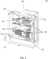
- Power distribution module 102 may comprise an enclosure 200 which may include AC input 110, AC output 112, front interior volume 202, front rail 204, front components 206, front volume panels 208, front volume width 210, front volume depth 212, lip distance 214, side lips 216, bottom lip 218, back interior volume 302, back rail 304, back components 306, back volume width 308, back volume depth 310, and handles 312, as shown.
- enclosure 200 may include AC input 110, AC output 112, front interior volume 202, front rail 204, front components 206, front volume panels 208, front volume width 210, front volume depth 212, lip distance 214, side lips 216, bottom lip 218, back interior volume 302, back rail 304, back components 306, back volume width 308, back volume depth 310, and handles 312, as shown.
- Front components 206 and back components 306 may form circuit branches 116 to distribute AC input 110 to AC output 112.
- Front components 206 and back components 306 may include circuit breakers, contactors, line filters and terminal blocks.
- Front components 206 may be affixed to one or more of front rail(s) 204 mounted within enclosure 200, while back components 306 may be affixed to one or more of back rail(s) 304 mounted within enclosure 200.
- Front components 206 may include components that would benefit from being more accessible from outside laser system 100.
- manually resettable circuit breakers may be included in front components 206 since, as shown in more detail hereinafter, front components 206 will be closer to the exterior of laser system 100 while back components 306 will be closer to the interior of laser system 100.
- Front components 206 and/or back components 306 may include circuit breakers to detect a fault and interrupt current flowing along one or more of AC outputs 112.
- Appropriate circuit breakers for use in power distribution module 102 may be arranged with protective relay pilot devices to sense a fault condition and to operate the trip opening mechanism.
- Such circuit breakers may be energized by a separate power source or may be self-contained along with current transformers and an internal control power source.
- the circuit breakers may be one, two, three, or four pole and may be magnetic circuit breakers, thermal magnetic circuit breakers, common trip breakers, or medium-voltage circuit breakers.
- Front components 206 and/or back components 306 may include contactors for switching power on and off to one or more of AC outputs 112.
- the contactors incorporated may be controlled by software, firmware, or other inputs such as toggles or buttons.
- Appropriate contactors for use in power distribution module 102 may be multi-pole and multi-throw or single-pole and single-throw.
- Front components 206 and/or back components 306 may include line filters to attenuate EMI on AC input 110.
- Appropriate line filters for use in power distribution module 102 may be able to attenuate in common mode or differential mode either passively or actively.
- Front components 206 and/or back components 306 may include terminal blocks to connect electrical wires.
- Appropriate terminal blocks for use in power distribution module 102 may include clamping plates to hold wires in place with tightening screws.
- AC input 110 and AC output 112 may be provided in the form of a collection of cables.
- AC input 110 includes a collection of 6 gauge shielded wires.
- AC output 112 includes a collection of 8 gauge shielded wires.
- the number of shielded wires in AC output 112 is greater than or equal to the number of laser modules included in laser system 100.
- AC input 110 and AC output 112 are three phase AC voltage.
- Enclosure 200 may include front interior volume 202 and back interior volume 302 of differing dimensions.
- Front interior volume 202 may have a front volume width 210 that is orthogonal to a front volume depth 212.
- back interior volume 302 may have a back volume width 308 that is orthogonal to a back volume depth 310.
- front volume width 210 is greater than back volume width 308, while back volume depth 310 is greater than front volume depth 212.
- a dual-cuboid shape to enclosure 200 created by front interior volume 202 and back interior volume 302 may facilitate efficient use of space in a rear compartment of a system rack design by allowing front interior volume 202 to stay near the outside of the system rack, while the narrower and deeper back interior volume 302 protrudes further into the system rack.
- Front rail 204 and back rail 304 may bifurcate, or span an interface between, front interior volume 202 and back interior volume 302.
- Front rail 204 may have a length slightly less than front volume width 210 and may have end portions mounted (for example with screws) to front volume panels 208.
- Back rail 304 may have a length slightly less than back volume width 308 and may be mounted (for example with screws) to a center portion of front rail 204. While shown as being mounted horizontally, front rail 204 and back rail 304 may be mounted vertically or may comprise both horizontal and vertical rails. Also, while shown as including two front rails 204 and two back rails 304, any number of front rails 204 and back rails 304 may be used.
- Front components 206 and back components 306 may be placed on front rail 204 or back rail 304 based in part on their width or depth.
- one or more of back components 306, affixed to back rail 304 have a depth greater than front volume depth 212 but less than back volume depth 310.
- front components 206 include a plurality of circuit breakers affixed to front rail 204 and back components 306 include a plurality of contactors affixed to back rail 304.
- a back component 306, affixed to back rail 304 includes a DC power supply, having a depth greater than front volume depth 212, electrically coupled with additional back components 306 (for example contactors).
- a DC power supply may be 24V and may provide power through an opening in enclosure 200 to additional auxiliary elements of laser system 100, for example LED lights, sensors, fans, pumps or other system level electrical parts that don't require a high voltage AC.
- Fig. 4 is a drawing of example rails, in accordance with some embodiments.
- Rails 400A and 400B may be standard metal rails and may have matching bend profiles 402.
- bend profile 402 comprises a top hat standard.
- rails 400A and 400B comply with a DIN standard.
- the back of rail 400A may be facing (or even touching) the back of rail 400B.
- Rails 400A and 400B may be coupled to each other with one or more fastener(s) 404 (for example a screw).
- rails 400A and 400B represent a cross-section of front rail 204 and back rail 304 in enclosure 200.
- rails 204 and 304 are 35 mm wide and 15 mm deep.
- rails 204 and 304 are 7.5 mm deep. While shown as both being top hat, sometimes referred to as Type O or Type Omega rails, rail 204 and rail 304 may be other types of rail and may differ from each other. For example, rail 204 may be a top hat rail section and rail 304 may be a C section rail or vice versa. Similarly, rail 204 may be a G type rail section in some embodiments. Also, miniature or extra-wide rail sections may be utilized in some embodiments.
- Fig. 5 is a drawing of an example component, in accordance with some embodiments.
- component 500 may represent front components 206 or back components 306.
- Component 500 may include a rail-mount 502.
- rail-mount 502 enables component 500 to be affixed to a standard metal rail (for example rails 400A, 400B, 204 and 304).
- rail-mount 502 complies with a DIN standard.
- Component 500 may have a rating 504 that defines its operating capacity. While shown as having a rating 504 of 480VAC, the present invention is not so limited.
- Component 500 may have a depth 506 that may be considered when determining where to affix component 500 within enclosure 200.
- Components 500 that have a rating 504 of handling 380VAC for example, may have a significantly shallower depth 506 than components 500 that have a rating 504 of 480VAC.
- rail-mount 502 may include additional parts or features.
- rail-mount 502 may be spring loaded with a lever that expands the opening of rail-mount 502 when component 500 is being added to or removed from the bends of a rail (for example rail 400A), and which contracts rail-mount 502 when the lever is not pressed.
- a screw adjustment or plastic clips may be present to expand or contract rail-mount 502.
- component 500 is UL certified.
- Laser system 100 may include rack 600, power distribution module 102, exit fiber 108, laser modules 602, side lips 216, and struts 604.
- Rack 600 may provide the structure and mounting points for supporting and containing the various modules of laser system 100.
- Rack 600 may be of standard or non-standard dimensions.
- Rack 600 may include additional elements not shown or may be implemented without all elements shown (for example wheels).
- rack 600 includes a 23-inch standardized rack frame for mounting laser modules 602. In some embodiments, rack 600 includes a 19-in standardized rack frame. In other embodiments, different rack widths may be used. In some embodiments the height of rack 600 is standardized in multiples of 1.752 inches or one rack unit or U. In one embodiment, rack 600 is 28 U tall. In other embodiments different rack heights may be used. In some embodiments, rack 600 is a four vertical post rack that allows for mounting rails to support laser modules 602 at the front and rear. In other embodiments, rack 600 is a two vertical post rack. In some embodiments, rack 600 is open in construction, while in other embodiments rack 600 is enclosed, for example by doors, side panels and a top.
- Rack 600 may have provisions for airflow and cooling of laser modules 602.
- front and/or side air intakes are included as well as rear exhaust. Forced air fan cooling may or may not be included.
- water cooling is provided to each of laser modules 602 in the form of cold plates supported by hoses, pumps, water inlets, water outlets, and drains.
- Power distribution module 102 and laser modules 602 are mounted within rack 600.
- Side lips 216 of enclosure 200 may interface with struts 604, which may extend vertically and define sides of an opening within rack 600.
- Fastener holes may be included in side lips 216 and struts 604 to fasten power distribution module 102 within rack 600.
- Exit fiber 108 may exit laser system 100 through an opening in rack 600. Exit fiber 108 may include many feet of optical fiber to interface with external tools (not shown).
- Fig. 7 is a 3D drawing of a power distribution module in an opening of a laser system rack, in accordance with some embodiments.
- laser system 100 may include rack 600, cross-member 702, flange 704, bottom panel 706, cross-member height 708, enclosure 200, bottom lip 218, handles 312, AC input 110, AC output 112, bottom module 710, and service loops 712.
- Flange 704 may extend vertically from horizontal cross-member 702 and may define a bottom of an opening in rack 600.
- Bottom lip 218 of enclosure 200 may engage an edge of flange 704 as a fulcrum point to allow enclosure 200 to pivot.
- Bottom lip 218 and flange 704 may interlock with each other such that flange 704 occupies space between bottom lip 218 and enclosure 200.
- Cross-member height 708, or the distance from flange 704 to bottom panel 706, may be greater than lip distance 214, or the distance from bottom lip 218 to a bottom of enclosure 200 (see Fig. 2 ), such that flange 704 supports the weight of enclosure 200 when fully seated in rack 600.
- the power distribution module enclosure 200 may be able to pivot (for example when a force is applied to handles 312) in a range between a first pivot angle 802 (as depicted in Fig. 8 ) and a second pivot angle 902 (as depicted in Fig. 9 ) relative to rack 600.
- First pivot angle 802 may be approximately 90 degrees
- second pivot angle 902 may be approximately 180 degrees.
- first pivot angle 802 represents fully seating of enclosure 200 in rack 600 such that side lips 216 can be fastened to struts 604.
- second pivot angle 902 can be beneficial when a technician need to access the interior of rack 600, for example to service bottom module 710.
- the engagement between bottom lip 218 and flange 704 is metal-on-metal, however in other embodiments plastic or other material may be included on portions of bottom lip 218 and/or flange 704 to reduce friction or eliminate sharp edges.
- support chain 804 is coupled to rack 600 and enclosure 200.
- Support chain 804 may be slack when enclosure 200 is at first pivot angle 802 ( Fig. 8 ).
- Support chain 804 may be under tension by a portion of the weight of enclosure 200 not carried by flange 704 at second pivot angle 902 ( Fig. 9 ).
- the length of support chain 804 defines the extent of second pivot angle 902.
- Support chain 804 may be made of metal chain links or cable.
- support chain 804 is made of non-metal material, such as synthetic fabric.
- support chain 804 includes a second support chain.
- the cables that make up AC input 110 and AC output 112 may include sufficient length to form service loops 712 disposed between bottom module 710 and bottom panel 706.
- Service loops 712 provide sufficient length to maintain electrical connection between the power distribution module and the laser modules 602 even when enclosure 200 is outside of rack 600, as shown in Fig. 10 .
- service loops 712 include about an extra two feet in length in each cable.
- posts or zip-ties or tie-downs are included to arrange and/or contain service loops 712.
- the cables that make up AC input 110 may electrically couple power distribution module 102 with one or more connectors on a side of rack 600 to receive power through an external cable(s) and power outlet(s).
- AC input 110 may include separate cables for L1 (black), L2 (red), L3 (blue), Neutral (white) and Ground (green).
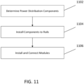
- FIG. 11 A flowchart of an example method, in accordance with some embodiments, is shown in Fig. 11 .
- the method begins with determining (1102) the power distribution components needed to form circuit branches 116.
- a laser system 100 may be designed for a specific purpose or customer and may have unique power requirements.
- Components 500 may be chosen based on a rating 504 to handle specific voltages or currents. Some factors that may influence power distribution component selection decisions may include maximum average power, maximum peak power, power tunability, power variation, modulation frequency, rise/fall times, beam quality, wavelength, operating voltage and operating voltage frequency.
- components needed to form circuit branches 116 may include circuit breakers, line filters, contactors, and/or terminal blocks.
- the number of components needed may be based on the number of laser modules 602 to be included in laser system 100. For example, in some embodiments, where 6 laser modules 602 are to be included in laser system 100, 6 circuit breakers, line filters, and contactors are included in power distribution module 102.
- Front components 206 may be mounted to front rail 204 and back components 306 may be mounted to back rail 304 based in part on a component depth 506.
- the components can be electrically coupled to form circuit branches 116 before or after being mounted to rails within enclosure 200.
- a DC power supply which has a depth greater than front volume depth 212, is mounted to back rail 304.
- circuit breakers are installed to front rail 204 in part because they may be more easily accessible to a service technician in the event of a fault.
- Components used may have internal spring actions, such that a component rail-mount snaps firmly into place on a standard metal rail, such as a DIN rail.
- components may include a screw adjustment to hold them in place on the rail.
- locations of components on the rails may be chosen to minimize wire routing. For example, line filters and/or circuit breakers may be placed in a location closer to AC inputs 110 since their functionality may be beneficial to subsequent down-stream components.
- the method concludes with installing (1106) power distribution module 102 in rack 600 and connecting AC outputs 112 to laser modules 602. Electrical connections may be established to and from power distribution module 102 through AC inputs 110 and AC outputs 112 while enclosure 200 is outside of rack 600. In addition to connecting AC inputs 110 and AC outputs 112 within rack 600, connections may also be made with a DC power supply within enclosure 200 to other elements within rack 600, for example LED lights, sensors, fans, pumps or other system level electrical parts that don't require a high voltage AC.
- Excess length of cable of AC inputs 110 and AC outputs 112 may be formed into service loops 712 and disposed between bottom module 710 and bottom panel 706.
- Handle(s) 312 may be used to lift enclosure 200 into an opening in rack 600 and to place bottom lip 218 into contact with flange 704.
- Support chain 804 may then be coupled with enclosure 200 and rack 600.
- Enclosure 200 can then be pivoted to first pivot angle 802, such that side lips 216 are interfacing with struts 604. Screws may then be installed through side lips 216 and struts 604 to secure power distribution module 102 within rack 600.
- enclosure 200 may be pivoted (after removing any screws fastening side lips 216 with struts 604) from first pivot angle 802 to second pivot angle 902. If necessary enclosure 200 can be disconnected from support chain 804 and placed outside of rack 600 while electrical connection is maintained to modules 602 because of the length of cable provided by service loops 712.
Landscapes
- Physics & Mathematics (AREA)
- Optics & Photonics (AREA)
- General Physics & Mathematics (AREA)
- Condensed Matter Physics & Semiconductors (AREA)
- Electromagnetism (AREA)
- Engineering & Computer Science (AREA)
- Plasma & Fusion (AREA)
- Mechanical Engineering (AREA)
- Lasers (AREA)
- Laser Beam Processing (AREA)
Description
- The present application claims priority to
United States Provisional Patent Application No. 62/380,258 filed on August 26, 2016 - Lasers are commonly used in materials processing, including cutting, welding, brazing, surface treatment and other applications. The power needs of a high power laser system can exceed that of most homes. The laser industry continues to increase laser performance metrics, such as average power, pulse energy and peak power. Increases in VAC typically require redesigned AC distribution systems. The circuit branches that distribute power to laser modules are typically housed in a metal box within the laser system. Customers tend to prefer laser systems that take up as little space as possible and that can be serviced quickly. Customers also tend to prefer less expensive laser systems that meet their needs. Therefore, there is a need for laser power distribution modules that enhance system serviceability and space efficiency, while reducing product development costs.
-
US2015/0349481 discloses a modular and scalable high-power laser system.JP2016/115761 US2015/0214700 discloses an AC circuit breaker panel including a housing having a front side, a bus bar positioned in the housing and one or more terminal blocks positioned in the housing.US2009/0323258 discloses a plug-in module for installation in a power distribution assembly. - According to a first aspect the invention is defined by a laser system as claimed in claim 1. Preferred embodiments are disclosed in the dependent claims.
- The material described herein is illustrated by way of example and not by way of limitation in the accompanying figures. For simplicity and clarity of illustration, elements illustrated in the figures are not necessarily drawn to scale. For example, the dimensions of some elements may be exaggerated relative to other elements for clarity. Further, where considered appropriate, reference labels have been repeated among the figures to indicate corresponding or analogous elements. In the figures:
-
FIG. 1 is a block diagram of an example laser system, in accordance with some embodiments; -
FIG. 2 is a cutaway drawing of an example power distribution module from one side, in accordance with some embodiments; -
FIG. 3 is a cutaway drawing of an example power distribution module from another side, in accordance with some embodiments; -
FIG. 4 is a drawing of an example rail, in accordance with some embodiments; -
FIG. 5 is a drawing of an example component, in accordance with some embodiments; -
FIG. 6 is a 3D drawing of an example laser system, in accordance with some embodiments; -
FIG. 7 is a 3D drawing of a power distribution module in an opening of a laser system rack, in accordance with some embodiments; -
FIG. 8 is a drawing of a power distribution module at a first pivot angle in a laser system rack, in accordance with some embodiments; -
FIG. 9 is a 3D drawing of a power distribution module at a second pivot angle in a laser system rack, in accordance with some embodiments; -
FIG. 10 is a 3D drawing of a power distribution module outside of a laser system rack, in accordance with some embodiments; and -
FIG. 11 is a flowchart of an example method, in accordance with some embodiments. - One or more embodiments are described with reference to the enclosed figures. While specific configurations and arrangements are depicted and discussed in detail, it should be understood that this is done for illustrative purposes only. Persons skilled in the relevant art will recognize that other configurations and arrangements are possible without departing from the scope of the description. It will be apparent to those skilled in the relevant art that techniques and/or arrangements described herein may be employed in a variety of other systems and applications other than what is described in detail herein.
- Reference is made in the following detailed description to the accompanying drawings, which form a part hereof and illustrate exemplary embodiments. Further, it is to be understood that other embodiments may be utilized and structural and/or logical changes may be made without departing from the scope of claimed subject matter. It should also be noted that directions and references, for example, up, down, top, bottom, and so on, may be used merely to facilitate the description of features in the drawings. Therefore, the following detailed description is not to be taken in a limiting sense and the scope of claimed subject matter is defined solely by the appended claims.
- In the following description, numerous details are set forth. However, it will be apparent to one skilled in the art, that the present invention may be practiced without these specific details. In some instances, well-known methods and devices are shown in block diagram form, rather than in detail, to avoid obscuring the present invention. Reference throughout this specification to "an embodiment" or "one embodiment" means that a particular feature, structure, function, or characteristic described in connection with the embodiment is included in at least one embodiment of the invention. Thus, the appearances of the phrase "in an embodiment" or "in one embodiment" in various places throughout this specification are not necessarily referring to the same embodiment of the invention. It will also be understood that the term "and/or" as used herein refers to and encompasses any and all possible combinations of one or more of the associated listed items.
- The terms "coupled" and "connected," along with their derivatives, may be used herein to describe functional or structural relationships between components. It should be understood that these terms are not intended as synonyms for each other. Rather, in particular embodiments, "connected" may be used to indicate that two or more elements are in direct physical, optical, or electrical contact with each other. "Coupled" may be used to indicated that two or more elements are in either direct or indirect (with other intervening elements between them) physical or electrical contact with each other, and/or that the two or more elements co-operate or interact with each other (e.g., as in a cause an effect relationship).
- The terms "over," "under," "between," and "on" as used herein refer to a relative position of one component or material with respect to other components or materials where such physical relationships are noteworthy.
- As used throughout this description, and in the claims, a list of items joined by the term "at least one of" or "one or more of" can mean any combination of the listed terms. For example, the phrase "at least one of A, B or C" can mean A; B; C; A and B; A and C; B and C; or A, B and C.
- A laser system generally includes a rack with a plurality of laser modules mounted in the rack to drive light through an optical fiber exiting the system. A power distribution module is generally also included in the rack to distribute electricity through circuit branches coupled to the laser modules. In some embodiments described hereinafter, the rack may include a horizontal cross-member with a bottom rack flange extending vertically and defining a bottom of an opening in the rack. In some embodiments described hereinafter, the power distribution module may include an enclosure disposed in the rack opening, wherein a face of the enclosure including a bottom lip to engage an edge of the bottom rack flange as a fulcrum point over a range to allow the enclosure to pivot between first and second pivot angles relative to the rack. Also, in some embodiments, one or more rails may be mounted within the enclosure, and one or more circuit components associated with each circuit branch may include a rail-mount by which the component is affixed to the one or more rails.
- Some benefits of the laser power distribution module described hereinafter include, but are not limited to, enhanced reusability, manufacturability, serviceability, and expandability. In other words, the same power distribution module enclosure with internal standard metal rails for component attachment can be used to house the components necessary to power many different laser systems in terms of maximum average power, maximum peak power, power tunability, power variation, modulation frequency, rise/fall times, beam quality, wavelength, operating voltage and operating voltage frequency. This can lead to reduced design time by allowing the same power distribution module enclosure to be reused among various product lines. Additionally, the use of standard metal rails can improve the assembly process in terms of speed and quality. Components can be aligned and mounted much quicker and more reliably compared with attempting to line up screw holes and attaching components with screws. Serviceability can be enhanced with the power distribution module described hereinafter by features that allow a technician/installer to pivot the power distribution module while it is being supported by the rack. This can allow access to those laser modules mounted low or at the bottom of a rack. Efficient use of space within the power distribution module enclosure can also leave room for larger and/or a higher number of components in the future as power needs increase.
- A block diagram of an example laser system that may benefit from incorporating embodiments of the present invention is depicted in
Fig. 1 . As shown,laser system 100 includespower distribution module 102,pump modules 104, combiner/gain module 106,exit fiber 108,AC input 110,AC output 112,optical fibers 114, andcircuit branches 116. Different and/or additional modules may be included inlaser system 100 without deviated from the scope of the present invention. For example, separate or multiple combiner/gain modules may be used. Also, any number ofpump modules 104 may be present. In one embodiment, six pump modules are included inlaser system 100.Laser system 100 may be a direct diode laser system, a fiber laser system, or any other type of laser system that may benefit from incorporating embodiments of the present invention. -
Power distribution module 102 may distribute power in the form of AC Voltage received asAC input 110 to pumpmodules 104 and combiner/gain module 106 throughAC output 112.Circuit branches 116 withinpower distribution module 102 may include circuit components to branchAC input 110 into multiple independent AC outputs 112. In some embodiments,AC input 110 is 3 phase AC which is distributed throughcircuit branches 116 as single phase AC outputs 112. -
Circuit branches 116 may include a circuit breaker, a contactor, a line filter, and/or a terminal block for eachAC output 112. The components ofcircuit branches 116 may be chosen based on the voltage and current requirements ofmodules AC outputs 112 provide 480VAC, though the present invention is not so limited. In some embodiments,AC output 112 may vary by module. For example,AC output 112 may deliver a different voltage or a same voltage at a different amperage to pumpmodule 104 thanAC output 112 delivers to combiner/gain module 106. -
Circuit branches 116 may be designed to protect modules coupled withAC outputs 112 from damage caused by overcurrent or overload or short circuit.Circuit branches 116 may interrupt current flow through one or more ofAC outputs 112 after protective relays detect a fault.Circuit branches 116 may be manually or automatically resettable after a fault. Additionally,circuit branches 116 may attenuate conducted electromagnetic interference (EMI) fromAC input 110 to AC outputs 112.Circuit branches 116 may be controlled by software or firmware either internal to or external fromlaser system 100. - One or
more pump modules 104 may be included inlaser system 100 to drive light throughoptical fibers 114. In some embodiments, each ofpump module 104 may include a DC power supply to convertAC output 112 into direct current that powers laser diodes. In some embodiments, each ofpump module 104 includes one or more liquid-cooled coldplate(s) for heat dissipation. - Combiner/
gain module 106 may include coiled fiber to increase light output and may combineoptical fibers 114 into asingle exit fiber 108 that exitslaser system 100. Additional modules (not shown) may be included inlaser system 100 to control and/or condition the light driven throughexit fiber 108 whenlaser system 100 is operating.Exit fiber 108 may have any diameter and length. In one embodiment,exit fiber 108 is up to 75 feet in length. Additionally, in some embodiments exitfiber 108 may be single clad while in some embodiments exitfiber 108 may be double clad. -
Figs. 2 and3 are cutaway drawings of an example power distribution module from different sides, in accordance with some embodiments.Power distribution module 102 may comprise anenclosure 200 which may includeAC input 110,AC output 112, frontinterior volume 202,front rail 204,front components 206,front volume panels 208,front volume width 210,front volume depth 212,lip distance 214,side lips 216,bottom lip 218, backinterior volume 302, backrail 304, backcomponents 306, backvolume width 308, backvolume depth 310, and handles 312, as shown. -
Front components 206 andback components 306 may formcircuit branches 116 to distribute AC input 110 toAC output 112.Front components 206 andback components 306 may include circuit breakers, contactors, line filters and terminal blocks.Front components 206 may be affixed to one or more of front rail(s) 204 mounted withinenclosure 200, while backcomponents 306 may be affixed to one or more of back rail(s) 304 mounted withinenclosure 200.Front components 206 may include components that would benefit from being more accessible fromoutside laser system 100. For example, manually resettable circuit breakers may be included infront components 206 since, as shown in more detail hereinafter,front components 206 will be closer to the exterior oflaser system 100 whileback components 306 will be closer to the interior oflaser system 100. -
Front components 206 and/orback components 306 may include circuit breakers to detect a fault and interrupt current flowing along one or more of AC outputs 112. Appropriate circuit breakers for use inpower distribution module 102 may be arranged with protective relay pilot devices to sense a fault condition and to operate the trip opening mechanism. Such circuit breakers may be energized by a separate power source or may be self-contained along with current transformers and an internal control power source. The circuit breakers may be one, two, three, or four pole and may be magnetic circuit breakers, thermal magnetic circuit breakers, common trip breakers, or medium-voltage circuit breakers. -
Front components 206 and/orback components 306 may include contactors for switching power on and off to one or more of AC outputs 112. The contactors incorporated may be controlled by software, firmware, or other inputs such as toggles or buttons. Appropriate contactors for use inpower distribution module 102 may be multi-pole and multi-throw or single-pole and single-throw. -
Front components 206 and/orback components 306 may include line filters to attenuate EMI onAC input 110. Appropriate line filters for use inpower distribution module 102 may be able to attenuate in common mode or differential mode either passively or actively. -
Front components 206 and/orback components 306 may include terminal blocks to connect electrical wires. Appropriate terminal blocks for use inpower distribution module 102 may include clamping plates to hold wires in place with tightening screws. -
AC input 110 andAC output 112 may be provided in the form of a collection of cables. In oneembodiment AC input 110 includes a collection of 6 gauge shielded wires. In one embodiment,AC output 112 includes a collection of 8 gauge shielded wires. In some embodiments, the number of shielded wires inAC output 112 is greater than or equal to the number of laser modules included inlaser system 100. In some embodiments,AC input 110 andAC output 112 are three phase AC voltage. -
Enclosure 200 may include frontinterior volume 202 and backinterior volume 302 of differing dimensions. Frontinterior volume 202 may have afront volume width 210 that is orthogonal to afront volume depth 212. Similarly, backinterior volume 302 may have aback volume width 308 that is orthogonal to aback volume depth 310. In one embodiment,front volume width 210 is greater than backvolume width 308, while backvolume depth 310 is greater thanfront volume depth 212. One skilled in the art would appreciate that a dual-cuboid shape toenclosure 200 created by frontinterior volume 202 and backinterior volume 302 may facilitate efficient use of space in a rear compartment of a system rack design by allowing frontinterior volume 202 to stay near the outside of the system rack, while the narrower and deeper backinterior volume 302 protrudes further into the system rack. -
Front rail 204 and backrail 304 may bifurcate, or span an interface between, frontinterior volume 202 and backinterior volume 302.Front rail 204 may have a length slightly less thanfront volume width 210 and may have end portions mounted (for example with screws) tofront volume panels 208. Back rail 304 may have a length slightly less than backvolume width 308 and may be mounted (for example with screws) to a center portion offront rail 204. While shown as being mounted horizontally,front rail 204 and backrail 304 may be mounted vertically or may comprise both horizontal and vertical rails. Also, while shown as including twofront rails 204 and twoback rails 304, any number offront rails 204 and back rails 304 may be used. -
Front components 206 andback components 306 may be placed onfront rail 204 or backrail 304 based in part on their width or depth. In one embodiment, one or more ofback components 306, affixed to backrail 304, have a depth greater thanfront volume depth 212 but less than backvolume depth 310. In one embodiment,front components 206 include a plurality of circuit breakers affixed tofront rail 204 andback components 306 include a plurality of contactors affixed to backrail 304. In one embodiment, aback component 306, affixed to backrail 304, includes a DC power supply, having a depth greater thanfront volume depth 212, electrically coupled with additional back components 306 (for example contactors). In some embodiments, a DC power supply may be 24V and may provide power through an opening inenclosure 200 to additional auxiliary elements oflaser system 100, for example LED lights, sensors, fans, pumps or other system level electrical parts that don't require a high voltage AC. -
Fig. 4 is a drawing of example rails, in accordance with some embodiments.Rails bend profile 402 comprises a top hat standard. In one embodiment, rails 400A and 400B comply with a DIN standard. The back ofrail 400A may be facing (or even touching) the back ofrail 400B.Rails front rail 204 and backrail 304 inenclosure 200. In some embodiments,rails rails rail 204 andrail 304 may be other types of rail and may differ from each other. For example,rail 204 may be a top hat rail section andrail 304 may be a C section rail or vice versa. Similarly,rail 204 may be a G type rail section in some embodiments. Also, miniature or extra-wide rail sections may be utilized in some embodiments. - One skilled in the art would recognize that the use of quick attach rails can enable fast and easy interchangeability of components, thereby reducing both manufacturing time (and thereby cost), but also time and cost associated with servicing systems that require component replacement. From a design perspective, the use of rails (such as
front rail 204 and back rail 304) inpower distribution module 100 can lead to adoption of asingle enclosure 200 for multiple product lines. Provided there is adequate length of rail and depth of enclosure interior, various component quantities and ratings can be incorporated as needed. -
Fig. 5 is a drawing of an example component, in accordance with some embodiments. In some embodiments,component 500 may representfront components 206 or backcomponents 306.Component 500 may include a rail-mount 502. In one embodiment, rail-mount 502 enablescomponent 500 to be affixed to a standard metal rail (for example rails 400A, 400B, 204 and 304). In one embodiment, rail-mount 502 complies with a DIN standard.Component 500 may have arating 504 that defines its operating capacity. While shown as having arating 504 of 480VAC, the present invention is not so limited.Component 500 may have adepth 506 that may be considered when determining where to affixcomponent 500 withinenclosure 200.Components 500 that have arating 504 of handling 380VAC, for example, may have a significantlyshallower depth 506 thancomponents 500 that have arating 504 of 480VAC. - While not shown for simplicity, rail-
mount 502 may include additional parts or features. For example, rail-mount 502 may be spring loaded with a lever that expands the opening of rail-mount 502 whencomponent 500 is being added to or removed from the bends of a rail (forexample rail 400A), and which contracts rail-mount 502 when the lever is not pressed. In other embodiments a screw adjustment or plastic clips may be present to expand or contract rail-mount 502. In some embodiments,component 500 is UL certified. - Turning now to
Fig. 6 , a 3D drawing of an example laser system, in accordance with some embodiments, is shown.Laser system 100 may includerack 600,power distribution module 102,exit fiber 108,laser modules 602,side lips 216, and struts 604.Rack 600 may provide the structure and mounting points for supporting and containing the various modules oflaser system 100.Rack 600 may be of standard or non-standard dimensions.Rack 600 may include additional elements not shown or may be implemented without all elements shown (for example wheels). - In some embodiments,
rack 600 includes a 23-inch standardized rack frame for mountinglaser modules 602. In some embodiments,rack 600 includes a 19-in standardized rack frame. In other embodiments, different rack widths may be used. In some embodiments the height ofrack 600 is standardized in multiples of 1.752 inches or one rack unit or U. In one embodiment,rack 600 is 28 U tall. In other embodiments different rack heights may be used. In some embodiments,rack 600 is a four vertical post rack that allows for mounting rails to supportlaser modules 602 at the front and rear. In other embodiments,rack 600 is a two vertical post rack. In some embodiments,rack 600 is open in construction, while in other embodiments rack 600 is enclosed, for example by doors, side panels and a top. -
Rack 600 may have provisions for airflow and cooling oflaser modules 602. In some embodiments, front and/or side air intakes are included as well as rear exhaust. Forced air fan cooling may or may not be included. In some embodiments, water cooling is provided to each oflaser modules 602 in the form of cold plates supported by hoses, pumps, water inlets, water outlets, and drains. -
Power distribution module 102 and laser modules 602 (which may includepump module 104 and combiner/gain module 106) are mounted withinrack 600.Side lips 216 ofenclosure 200 may interface withstruts 604, which may extend vertically and define sides of an opening withinrack 600. Fastener holes may be included inside lips 216 and struts 604 to fastenpower distribution module 102 withinrack 600. -
Exit fiber 108 may exitlaser system 100 through an opening inrack 600.Exit fiber 108 may include many feet of optical fiber to interface with external tools (not shown). -
Fig. 7 is a 3D drawing of a power distribution module in an opening of a laser system rack, in accordance with some embodiments. As shown,laser system 100 may includerack 600, cross-member 702,flange 704,bottom panel 706,cross-member height 708,enclosure 200,bottom lip 218, handles 312,AC input 110,AC output 112,bottom module 710, andservice loops 712. -
Flange 704 may extend vertically fromhorizontal cross-member 702 and may define a bottom of an opening inrack 600.Bottom lip 218 ofenclosure 200 may engage an edge offlange 704 as a fulcrum point to allowenclosure 200 to pivot.Bottom lip 218 andflange 704 may interlock with each other such thatflange 704 occupies space betweenbottom lip 218 andenclosure 200.Cross-member height 708, or the distance fromflange 704 tobottom panel 706, may be greater thanlip distance 214, or the distance frombottom lip 218 to a bottom of enclosure 200 (seeFig. 2 ), such thatflange 704 supports the weight ofenclosure 200 when fully seated inrack 600. - The power
distribution module enclosure 200 may be able to pivot (for example when a force is applied to handles 312) in a range between a first pivot angle 802 (as depicted inFig. 8 ) and a second pivot angle 902 (as depicted inFig. 9 ) relative to rack 600.First pivot angle 802 may be approximately 90 degrees, whilesecond pivot angle 902 may be approximately 180 degrees. In some embodiments,first pivot angle 802 represents fully seating ofenclosure 200 inrack 600 such thatside lips 216 can be fastened to struts 604. One skilled in the art would appreciate thatsecond pivot angle 902 can be beneficial when a technician need to access the interior ofrack 600, for example to servicebottom module 710. In some embodiments, the engagement betweenbottom lip 218 andflange 704 is metal-on-metal, however in other embodiments plastic or other material may be included on portions ofbottom lip 218 and/orflange 704 to reduce friction or eliminate sharp edges. - In some embodiments,
support chain 804 is coupled to rack 600 andenclosure 200.Support chain 804 may be slack whenenclosure 200 is at first pivot angle 802 (Fig. 8 ).Support chain 804 may be under tension by a portion of the weight ofenclosure 200 not carried byflange 704 at second pivot angle 902 (Fig. 9 ). In some embodiments, the length ofsupport chain 804 defines the extent ofsecond pivot angle 902.Support chain 804 may be made of metal chain links or cable. In some embodiments,support chain 804 is made of non-metal material, such as synthetic fabric. In some embodiments,support chain 804 includes a second support chain. - Turning back to
Fig. 7 , the cables that make upAC input 110 andAC output 112 may include sufficient length to formservice loops 712 disposed betweenbottom module 710 andbottom panel 706.Service loops 712 provide sufficient length to maintain electrical connection between the power distribution module and thelaser modules 602 even whenenclosure 200 is outside ofrack 600, as shown inFig. 10 . In some embodiments,service loops 712 include about an extra two feet in length in each cable. In some embodiments, posts or zip-ties or tie-downs are included to arrange and/or containservice loops 712. The cables that make upAC input 110 may electrically couplepower distribution module 102 with one or more connectors on a side ofrack 600 to receive power through an external cable(s) and power outlet(s).AC input 110 may include separate cables for L1 (black), L2 (red), L3 (blue), Neutral (white) and Ground (green). - A flowchart of an example method, in accordance with some embodiments, is shown in
Fig. 11 . The method begins with determining (1102) the power distribution components needed to formcircuit branches 116. Alaser system 100 may be designed for a specific purpose or customer and may have unique power requirements.Components 500 may be chosen based on arating 504 to handle specific voltages or currents. Some factors that may influence power distribution component selection decisions may include maximum average power, maximum peak power, power tunability, power variation, modulation frequency, rise/fall times, beam quality, wavelength, operating voltage and operating voltage frequency. - In some embodiments, components needed to form
circuit branches 116 may include circuit breakers, line filters, contactors, and/or terminal blocks. The number of components needed may be based on the number oflaser modules 602 to be included inlaser system 100. For example, in some embodiments, where 6laser modules 602 are to be included inlaser system 100, 6 circuit breakers, line filters, and contactors are included inpower distribution module 102. - The method continues with installing (1104) components to rails in
enclosure 200.Front components 206 may be mounted tofront rail 204 andback components 306 may be mounted to backrail 304 based in part on acomponent depth 506. The components can be electrically coupled to formcircuit branches 116 before or after being mounted to rails withinenclosure 200. In one embodiment, a DC power supply, which has a depth greater thanfront volume depth 212, is mounted to backrail 304. In one embodiment circuit breakers are installed tofront rail 204 in part because they may be more easily accessible to a service technician in the event of a fault. - Components used may have internal spring actions, such that a component rail-mount snaps firmly into place on a standard metal rail, such as a DIN rail. In some embodiments, components may include a screw adjustment to hold them in place on the rail. In some embodiments, locations of components on the rails may be chosen to minimize wire routing. For example, line filters and/or circuit breakers may be placed in a location closer to
AC inputs 110 since their functionality may be beneficial to subsequent down-stream components. - The method concludes with installing (1106)
power distribution module 102 inrack 600 and connectingAC outputs 112 tolaser modules 602. Electrical connections may be established to and frompower distribution module 102 throughAC inputs 110 andAC outputs 112 whileenclosure 200 is outside ofrack 600. In addition to connectingAC inputs 110 andAC outputs 112 withinrack 600, connections may also be made with a DC power supply withinenclosure 200 to other elements withinrack 600, for example LED lights, sensors, fans, pumps or other system level electrical parts that don't require a high voltage AC. - Excess length of cable of
AC inputs 110 andAC outputs 112 may be formed intoservice loops 712 and disposed betweenbottom module 710 andbottom panel 706. Handle(s) 312 may be used to liftenclosure 200 into an opening inrack 600 and to placebottom lip 218 into contact withflange 704.Support chain 804 may then be coupled withenclosure 200 andrack 600.Enclosure 200 can then be pivoted tofirst pivot angle 802, such thatside lips 216 are interfacing withstruts 604. Screws may then be installed throughside lips 216 and struts 604 to securepower distribution module 102 withinrack 600. - Portions of this method may be performed in reverse order for disassembly or servicing of
laser system 100. For example, to servicebottom module 710,enclosure 200 may be pivoted (after removing any screws fasteningside lips 216 with struts 604) fromfirst pivot angle 802 tosecond pivot angle 902. Ifnecessary enclosure 200 can be disconnected fromsupport chain 804 and placed outside ofrack 600 while electrical connection is maintained tomodules 602 because of the length of cable provided byservice loops 712. - While certain features set forth herein have been described with reference to various implementations, this description is not intended to be construed in a limiting sense. The scope of the invention should, therefore, be determined with reference to the appended claims.
Claims (15)
- A laser system (100), comprising:a rack (600);a plurality of laser modules (602) mounted in the rack (600) to drive light through an optical fiber (108) exiting the system (100); anda power distribution module (102) disposed within the rack (600) to distribute input electricity through circuit branches (116) coupled to the laser modules (602), wherein the power distribution module (102) is characterized by further comprising:an enclosure (200);one or more rails (204, 304, 400A, 400B) mounted within the enclosure (200), wherein the rails bifurcate (204, 304, 400A, 400B) an interior volume (202, 302) of the enclosure into front (202) and back (302) volumes; andone or more circuit components associated with each circuit branch (116) disposed within the enclosure (200), each of the circuit components including a rail-mount (502) by which the circuit component is affixed to the one or more rails (204, 304, 400A, 400B), wherein a rail-mount (502) of a first of the circuit components is affixed to the one or more rails (204, 304, 400A, 400B) and the first of the circuit components occupies a portion of the front volume, and wherein a rail-mount (502) of a second of the circuit components is affixed to the one or more rails (204, 304, 400A, 400B) and the second of the circuit components occupies a portion of the back volume.
- The system (100) of claim 1, wherein
the one or more rails (204, 304, 400A, 400B) further comprise a first rail (400A) having a back facing a back of a second rail (400B), the first rail-mount affixed to a front of the first rail (400A) and the second rail-mount affixed to a front of the second rail (400B). - The system (100) of claim 2, wherein:the first rail (400A) and the second rail (400B) have a same bend profile;andthe first and second circuit components have a same standard-compliant rail-mount (502).
- The system (100) of claim 3, wherein the rails (400A, 400B) comprise DIN-compliant rails and the bend profile comprises a top hat.
- The system (100) of claim 3, wherein:end portions of the first rail (400A) are mounted to first and second panels of the enclosure;the second rail (400B) is mounted to a center portion of the first rail (400A);the front volume (202) has a front width (210) at least equal to the length of the first rail (400A); andthe back volume (302) has a back width (308) at least equal to the length of the second rail (400B).
- The system (100) of claim 5, wherein the back width (308) is smaller than the front width (210).
- The system (100) of claim 6, wherein:the front volume has a front depth (212) orthogonal to the front width (210);the back volume has a back depth (310), greater than the front depth (212); andthe one or more circuit components further comprise a component affixed to the second rail (400B) that has a depth greater than the front depth (212), but less than the back depth (310).
- The system (100) of any one of claims 1-7, wherein the circuit components are selected from the group consisting of: circuit breakers, terminal blocks, line filters, and contactors.
- The system (100) of claim 8, wherein:the front volume has a front depth (212) orthogonal to the front width (210);the back volume has a back depth (310), greater than the front depth (212); andthe one or more circuit components further comprise:a plurality of circuit breakers affixed to the first rail; anda plurality of contactors affixed to the second rail.
- The system (100) of claim 9, wherein the power distribution module (102) further comprises a DC power supply coupled to power each of the contactors and affixed to the second rail (400B) to occupy a portion of the back volume.
- The laser system (100) of claim 1, wherein:the rack (600) includes a horizontal cross-member (702) with a bottom rack flange (704) extending vertically and defining a bottom of an opening in the rack (600), and;the enclosure (200) is disposed in the rack opening, a face of the enclosure including a bottom lip (218) to engage an edge of the bottom rack flange (704) as a fulcrum point over a range to allow the enclosure to pivot between first (802) and second pivot angles (902) relative to the rack.
- The system (100) of claim 11, wherein:the rack (600) includes struts (604) extending vertically and defining sides of the rack opening;the enclosure face further includes a first and second side lip (216) to interface with the struts at the first pivot angle; anda distance between the bottom lip (218) and a bottom of the enclosure is less than a distance between the edge of the bottom rack flange (704) and a bottom panel of the rack so that the flange (704) supports the weight of the enclosure while at the first pivot angle (802).
- The system (100) of claim 11 or 12, wherein:the rack (600) includes a support chain (804) coupled to the enclosure (200) and the rack (600);a length of the support chain (804) defines the second pivot angle (902); andthe support chain (804) is to be placed under tension by a portion of the enclosure weight not carried by the flange while at the second pivot angle (902).
- The system (100) of claim 11 or 12, wherein the cables each include a service loop (712) of sufficient length to maintain an electrical connection between the laser modules (602) and distribution module (102) while the lip is disengaged from the flange.
- The system of claim 14, wherein the service loop (712) is disposed between a bottom module (710) and a bottom panel (706) of the rack (600) while the enclosure is at the first pivot angle (802).
Applications Claiming Priority (2)
| Application Number | Priority Date | Filing Date | Title |
|---|---|---|---|
| US201662380258P | 2016-08-26 | 2016-08-26 | |
| PCT/US2017/048673 WO2018039594A1 (en) | 2016-08-26 | 2017-08-25 | Laser power distribution module |
Publications (3)
| Publication Number | Publication Date |
|---|---|
| EP3504944A1 EP3504944A1 (en) | 2019-07-03 |
| EP3504944A4 EP3504944A4 (en) | 2020-04-15 |
| EP3504944B1 true EP3504944B1 (en) | 2023-06-07 |
Family
ID=61241414
Family Applications (1)
| Application Number | Title | Priority Date | Filing Date |
|---|---|---|---|
| EP17844509.4A Active EP3504944B1 (en) | 2016-08-26 | 2017-08-25 | Laser power distribution module |
Country Status (4)
| Country | Link |
|---|---|
| US (1) | US11027366B2 (en) |
| EP (1) | EP3504944B1 (en) |
| CN (1) | CN109863837B (en) |
| WO (1) | WO2018039594A1 (en) |
Families Citing this family (3)
| Publication number | Priority date | Publication date | Assignee | Title |
|---|---|---|---|---|
| CN109713557B (en) * | 2019-03-14 | 2024-04-30 | 苏州创鑫激光科技有限公司 | High-power multi-module laser and photoelectric module thereof |
| JP2021093398A (en) * | 2019-12-06 | 2021-06-17 | ファナック株式会社 | Laser oscillator having high maintainability |
| WO2023026487A1 (en) * | 2021-08-27 | 2023-03-02 | ファナック株式会社 | Laser oscillator powered through power cable |
Family Cites Families (26)
| Publication number | Priority date | Publication date | Assignee | Title |
|---|---|---|---|---|
| JPS57199286A (en) * | 1981-06-02 | 1982-12-07 | Toshiba Corp | Semiconductor laser device |
| US4885436A (en) * | 1988-08-29 | 1989-12-05 | Tandem Computers Incorporated | Electronic module interlock and extraction mechanism |
| US5010426A (en) * | 1989-02-03 | 1991-04-23 | Zenith Data Systems Corporation | Installation mechanism for removable computer drive module |
| US5863017A (en) * | 1996-01-05 | 1999-01-26 | Cymer, Inc. | Stabilized laser platform and module interface |
| US6128323A (en) * | 1997-04-23 | 2000-10-03 | Cymer, Inc. | Reliable modular production quality narrow-band high REP rate excimer laser |
| US6757316B2 (en) * | 1999-12-27 | 2004-06-29 | Cymer, Inc. | Four KHz gas discharge laser |
| DE19954855C1 (en) * | 1999-11-15 | 2001-04-05 | Siemens Ag | Automatic treatment or handling system for fluids using series of interchangeable process modules, includes electronic-bus-connected controllers and fluid-bus-connected fluid treatment modules |
| US7054342B2 (en) * | 2001-03-02 | 2006-05-30 | Ilx Lightwave Corporation | High density optical source bank |
| US6498716B1 (en) * | 2001-08-21 | 2002-12-24 | Compaq Information Technologies Group, L.P. | DC main power distribution |
| US7379305B2 (en) * | 2004-01-23 | 2008-05-27 | American Power Conversion Corporation | Modular UPS |
| US7529097B2 (en) * | 2004-05-07 | 2009-05-05 | Rackable Systems, Inc. | Rack mounted computer system |
| DE202004018857U1 (en) * | 2004-12-07 | 2005-02-24 | Abb Patent Gmbh | metal housing |
| US7274851B2 (en) * | 2005-10-18 | 2007-09-25 | Hewlett-Packard Development Company, L.P. | Fiber optic module |
| US7606014B2 (en) | 2006-06-16 | 2009-10-20 | American Power Conversion Corporation | Apparatus and method for scalable power distribution |
| US20100110621A1 (en) * | 2008-10-31 | 2010-05-06 | Liebert Corporation | Rack with vertical mounting providing room for rack pdu |
| GB201107860D0 (en) | 2011-05-11 | 2011-06-22 | Manda Ion | Rack module |
| BR112013030765A2 (en) * | 2011-05-31 | 2016-12-06 | Eaton Corp | power distribution set for an electrical system and system |
| CN202308826U (en) * | 2011-10-26 | 2012-07-04 | 南车青岛四方机车车辆股份有限公司 | Modularized power distribution cabinet combination for railway vehicles |
| CN104423491B (en) * | 2013-09-05 | 2017-09-12 | 纬创资通股份有限公司 | Connectable and pluggable rotary modules |
| CN203522508U (en) * | 2013-10-29 | 2014-04-02 | 深圳市英威腾电气股份有限公司 | Explosion-proof frequency converter |
| KR101572560B1 (en) * | 2013-12-26 | 2015-12-11 | 주식회사 효성 | Module apparatus for HVDC system |
| US9232678B2 (en) * | 2013-12-30 | 2016-01-05 | Dell Products L.P. | Modular, scalable, expandable, rack-based information handling system |
| US20150214700A1 (en) | 2014-01-29 | 2015-07-30 | Emerson Network Power, Energy Systems, North America, Inc. | Ac circuit breaker panels and telecommunications equipment cabinets having ac circuit breaker panels |
| US10069271B2 (en) | 2014-06-02 | 2018-09-04 | Nlight, Inc. | Scalable high power fiber laser |
| EP3207602B1 (en) * | 2014-10-15 | 2025-09-03 | Lumentum Operations LLC | Laser system and method of tuning the output power of the laser system |
| JP5879425B1 (en) | 2014-12-12 | 2016-03-08 | 株式会社フジクラ | Fiber laser device and optical fiber connection device |
-
2017
- 2017-08-25 CN CN201780064434.XA patent/CN109863837B/en active Active
- 2017-08-25 WO PCT/US2017/048673 patent/WO2018039594A1/en not_active Ceased
- 2017-08-25 US US15/687,047 patent/US11027366B2/en active Active
- 2017-08-25 EP EP17844509.4A patent/EP3504944B1/en active Active
Also Published As
| Publication number | Publication date |
|---|---|
| EP3504944A4 (en) | 2020-04-15 |
| US11027366B2 (en) | 2021-06-08 |
| CN109863837B (en) | 2022-07-08 |
| WO2018039594A1 (en) | 2018-03-01 |
| US20180056442A1 (en) | 2018-03-01 |
| EP3504944A1 (en) | 2019-07-03 |
| CN109863837A (en) | 2019-06-07 |
Similar Documents
| Publication | Publication Date | Title |
|---|---|---|
| US11027366B2 (en) | Laser power distribution module | |
| US7719823B2 (en) | Modular insulation system | |
| US9971116B2 (en) | Laser optical fiber tray | |
| US8908355B2 (en) | Emergency lighting control panel | |
| US10143093B2 (en) | Modular apparatus for high voltage direct-current transmission system | |
| US20160118933A1 (en) | Alternating current photovoltaic modules | |
| KR20130076672A (en) | Power conversion apparatus | |
| US7061759B2 (en) | Arrangement for the placement of frequency converters | |
| CN109713557B (en) | High-power multi-module laser and photoelectric module thereof | |
| KR20200030386A (en) | A distribution transformer with improved heat dissipation performance | |
| EP3032663A1 (en) | Power cabinet for medium-high voltage inverters | |
| KR20200120380A (en) | Connecting Clip and MCC with the same | |
| US10451823B2 (en) | Laser module service shelf | |
| CN210926726U (en) | Switch board convenient to adjust inside bearing structure | |
| JP2008253119A (en) | Distribution panel | |
| KR20170062065A (en) | Submodule for HVDC system | |
| CN217883210U (en) | Air-cooled power regulating power supply device for thyristor | |
| KR200479887Y1 (en) | Motor control center | |
| US20250279637A1 (en) | Remote power system rack and assembly | |
| CN110401121B (en) | Outdoor four-port electric energy router structure | |
| JP2005204464A (en) | Distribution board | |
| WO2014083078A1 (en) | Natural parallel ventilation inside a low voltage system | |
| JP2011097719A (en) | Power distribution panel | |
| WO2013138462A1 (en) | Cover guard and routing device |
Legal Events
| Date | Code | Title | Description |
|---|---|---|---|
| STAA | Information on the status of an ep patent application or granted ep patent |
Free format text: STATUS: THE INTERNATIONAL PUBLICATION HAS BEEN MADE |
|
| PUAI | Public reference made under article 153(3) epc to a published international application that has entered the european phase |
Free format text: ORIGINAL CODE: 0009012 |
|
| STAA | Information on the status of an ep patent application or granted ep patent |
Free format text: STATUS: REQUEST FOR EXAMINATION WAS MADE |
|
| 17P | Request for examination filed |
Effective date: 20190319 |
|
| AK | Designated contracting states |
Kind code of ref document: A1 Designated state(s): AL AT BE BG CH CY CZ DE DK EE ES FI FR GB GR HR HU IE IS IT LI LT LU LV MC MK MT NL NO PL PT RO RS SE SI SK SM TR |
|
| AX | Request for extension of the european patent |
Extension state: BA ME |
|
| DAV | Request for validation of the european patent (deleted) | ||
| DAX | Request for extension of the european patent (deleted) | ||
| A4 | Supplementary search report drawn up and despatched |
Effective date: 20200312 |
|
| RIC1 | Information provided on ipc code assigned before grant |
Ipc: G02B 6/42 20060101ALI20200306BHEP Ipc: H05K 5/03 20060101AFI20200306BHEP Ipc: H01S 5/40 20060101ALI20200306BHEP Ipc: H01S 3/10 20060101ALI20200306BHEP Ipc: G02B 6/34 20060101ALI20200306BHEP Ipc: G02B 6/38 20060101ALI20200306BHEP Ipc: G02B 6/26 20060101ALI20200306BHEP Ipc: H05K 5/02 20060101ALI20200306BHEP Ipc: H01S 5/042 20060101ALI20200306BHEP Ipc: G02B 6/44 20060101ALI20200306BHEP Ipc: H01S 3/00 20060101ALI20200306BHEP Ipc: H05K 7/14 20060101ALI20200306BHEP Ipc: H01S 3/02 20060101ALI20200306BHEP |
|
| RIC1 | Information provided on ipc code assigned before grant |
Ipc: H01S 5/40 20060101ALI20220502BHEP Ipc: H01S 5/042 20060101ALI20220502BHEP Ipc: G02B 6/44 20060101ALI20220502BHEP Ipc: H05K 7/14 20060101ALI20220502BHEP Ipc: G02B 6/42 20060101ALI20220502BHEP Ipc: G02B 6/38 20060101ALI20220502BHEP Ipc: G02B 6/34 20060101ALI20220502BHEP Ipc: G02B 6/26 20060101ALI20220502BHEP Ipc: H01S 3/02 20060101ALI20220502BHEP Ipc: H01S 3/10 20060101ALI20220502BHEP Ipc: H01S 3/00 20060101ALI20220502BHEP Ipc: H05K 5/02 20060101ALI20220502BHEP Ipc: H05K 5/03 20060101AFI20220502BHEP |
|
| GRAP | Despatch of communication of intention to grant a patent |
Free format text: ORIGINAL CODE: EPIDOSNIGR1 |
|
| STAA | Information on the status of an ep patent application or granted ep patent |
Free format text: STATUS: GRANT OF PATENT IS INTENDED |
|
| INTG | Intention to grant announced |
Effective date: 20220610 |
|
| GRAJ | Information related to disapproval of communication of intention to grant by the applicant or resumption of examination proceedings by the epo deleted |
Free format text: ORIGINAL CODE: EPIDOSDIGR1 |
|
| STAA | Information on the status of an ep patent application or granted ep patent |
Free format text: STATUS: REQUEST FOR EXAMINATION WAS MADE |
|
| INTC | Intention to grant announced (deleted) | ||
| GRAP | Despatch of communication of intention to grant a patent |
Free format text: ORIGINAL CODE: EPIDOSNIGR1 |
|
| STAA | Information on the status of an ep patent application or granted ep patent |
Free format text: STATUS: GRANT OF PATENT IS INTENDED |
|
| INTG | Intention to grant announced |
Effective date: 20221223 |
|
| GRAS | Grant fee paid |
Free format text: ORIGINAL CODE: EPIDOSNIGR3 |
|
| GRAA | (expected) grant |
Free format text: ORIGINAL CODE: 0009210 |
|
| STAA | Information on the status of an ep patent application or granted ep patent |
Free format text: STATUS: THE PATENT HAS BEEN GRANTED |
|
| AK | Designated contracting states |
Kind code of ref document: B1 Designated state(s): AL AT BE BG CH CY CZ DE DK EE ES FI FR GB GR HR HU IE IS IT LI LT LU LV MC MK MT NL NO PL PT RO RS SE SI SK SM TR |
|
| REG | Reference to a national code |
Ref country code: GB Ref legal event code: FG4D |
|
| REG | Reference to a national code |
Ref country code: CH Ref legal event code: EP Ref country code: AT Ref legal event code: REF Ref document number: 1578481 Country of ref document: AT Kind code of ref document: T Effective date: 20230615 |
|
| REG | Reference to a national code |
Ref country code: DE Ref legal event code: R096 Ref document number: 602017069907 Country of ref document: DE |
|
| P01 | Opt-out of the competence of the unified patent court (upc) registered |
Effective date: 20230523 |
|
| REG | Reference to a national code |
Ref country code: LT Ref legal event code: MG9D |
|
| REG | Reference to a national code |
Ref country code: NL Ref legal event code: MP Effective date: 20230607 |
|
| PG25 | Lapsed in a contracting state [announced via postgrant information from national office to epo] |
Ref country code: SE Free format text: LAPSE BECAUSE OF FAILURE TO SUBMIT A TRANSLATION OF THE DESCRIPTION OR TO PAY THE FEE WITHIN THE PRESCRIBED TIME-LIMIT Effective date: 20230607 Ref country code: NO Free format text: LAPSE BECAUSE OF FAILURE TO SUBMIT A TRANSLATION OF THE DESCRIPTION OR TO PAY THE FEE WITHIN THE PRESCRIBED TIME-LIMIT Effective date: 20230907 Ref country code: ES Free format text: LAPSE BECAUSE OF FAILURE TO SUBMIT A TRANSLATION OF THE DESCRIPTION OR TO PAY THE FEE WITHIN THE PRESCRIBED TIME-LIMIT Effective date: 20230607 |
|
| REG | Reference to a national code |
Ref country code: AT Ref legal event code: MK05 Ref document number: 1578481 Country of ref document: AT Kind code of ref document: T Effective date: 20230607 |
|
| PG25 | Lapsed in a contracting state [announced via postgrant information from national office to epo] |
Ref country code: RS Free format text: LAPSE BECAUSE OF FAILURE TO SUBMIT A TRANSLATION OF THE DESCRIPTION OR TO PAY THE FEE WITHIN THE PRESCRIBED TIME-LIMIT Effective date: 20230607 Ref country code: NL Free format text: LAPSE BECAUSE OF FAILURE TO SUBMIT A TRANSLATION OF THE DESCRIPTION OR TO PAY THE FEE WITHIN THE PRESCRIBED TIME-LIMIT Effective date: 20230607 Ref country code: LV Free format text: LAPSE BECAUSE OF FAILURE TO SUBMIT A TRANSLATION OF THE DESCRIPTION OR TO PAY THE FEE WITHIN THE PRESCRIBED TIME-LIMIT Effective date: 20230607 Ref country code: LT Free format text: LAPSE BECAUSE OF FAILURE TO SUBMIT A TRANSLATION OF THE DESCRIPTION OR TO PAY THE FEE WITHIN THE PRESCRIBED TIME-LIMIT Effective date: 20230607 Ref country code: HR Free format text: LAPSE BECAUSE OF FAILURE TO SUBMIT A TRANSLATION OF THE DESCRIPTION OR TO PAY THE FEE WITHIN THE PRESCRIBED TIME-LIMIT Effective date: 20230607 Ref country code: GR Free format text: LAPSE BECAUSE OF FAILURE TO SUBMIT A TRANSLATION OF THE DESCRIPTION OR TO PAY THE FEE WITHIN THE PRESCRIBED TIME-LIMIT Effective date: 20230908 |
|
| PG25 | Lapsed in a contracting state [announced via postgrant information from national office to epo] |
Ref country code: FI Free format text: LAPSE BECAUSE OF FAILURE TO SUBMIT A TRANSLATION OF THE DESCRIPTION OR TO PAY THE FEE WITHIN THE PRESCRIBED TIME-LIMIT Effective date: 20230607 |
|
| PG25 | Lapsed in a contracting state [announced via postgrant information from national office to epo] |
Ref country code: SK Free format text: LAPSE BECAUSE OF FAILURE TO SUBMIT A TRANSLATION OF THE DESCRIPTION OR TO PAY THE FEE WITHIN THE PRESCRIBED TIME-LIMIT Effective date: 20230607 |
|
| PG25 | Lapsed in a contracting state [announced via postgrant information from national office to epo] |
Ref country code: IS Free format text: LAPSE BECAUSE OF FAILURE TO SUBMIT A TRANSLATION OF THE DESCRIPTION OR TO PAY THE FEE WITHIN THE PRESCRIBED TIME-LIMIT Effective date: 20231007 |
|
| PG25 | Lapsed in a contracting state [announced via postgrant information from national office to epo] |
Ref country code: SM Free format text: LAPSE BECAUSE OF FAILURE TO SUBMIT A TRANSLATION OF THE DESCRIPTION OR TO PAY THE FEE WITHIN THE PRESCRIBED TIME-LIMIT Effective date: 20230607 Ref country code: SK Free format text: LAPSE BECAUSE OF FAILURE TO SUBMIT A TRANSLATION OF THE DESCRIPTION OR TO PAY THE FEE WITHIN THE PRESCRIBED TIME-LIMIT Effective date: 20230607 Ref country code: RO Free format text: LAPSE BECAUSE OF FAILURE TO SUBMIT A TRANSLATION OF THE DESCRIPTION OR TO PAY THE FEE WITHIN THE PRESCRIBED TIME-LIMIT Effective date: 20230607 Ref country code: PT Free format text: LAPSE BECAUSE OF FAILURE TO SUBMIT A TRANSLATION OF THE DESCRIPTION OR TO PAY THE FEE WITHIN THE PRESCRIBED TIME-LIMIT Effective date: 20231009 Ref country code: IS Free format text: LAPSE BECAUSE OF FAILURE TO SUBMIT A TRANSLATION OF THE DESCRIPTION OR TO PAY THE FEE WITHIN THE PRESCRIBED TIME-LIMIT Effective date: 20231007 Ref country code: EE Free format text: LAPSE BECAUSE OF FAILURE TO SUBMIT A TRANSLATION OF THE DESCRIPTION OR TO PAY THE FEE WITHIN THE PRESCRIBED TIME-LIMIT Effective date: 20230607 Ref country code: CZ Free format text: LAPSE BECAUSE OF FAILURE TO SUBMIT A TRANSLATION OF THE DESCRIPTION OR TO PAY THE FEE WITHIN THE PRESCRIBED TIME-LIMIT Effective date: 20230607 Ref country code: AT Free format text: LAPSE BECAUSE OF FAILURE TO SUBMIT A TRANSLATION OF THE DESCRIPTION OR TO PAY THE FEE WITHIN THE PRESCRIBED TIME-LIMIT Effective date: 20230607 |
|
| PG25 | Lapsed in a contracting state [announced via postgrant information from national office to epo] |
Ref country code: PL Free format text: LAPSE BECAUSE OF FAILURE TO SUBMIT A TRANSLATION OF THE DESCRIPTION OR TO PAY THE FEE WITHIN THE PRESCRIBED TIME-LIMIT Effective date: 20230607 |
|
| REG | Reference to a national code |
Ref country code: DE Ref legal event code: R097 Ref document number: 602017069907 Country of ref document: DE |
|
| PG25 | Lapsed in a contracting state [announced via postgrant information from national office to epo] |
Ref country code: MC Free format text: LAPSE BECAUSE OF FAILURE TO SUBMIT A TRANSLATION OF THE DESCRIPTION OR TO PAY THE FEE WITHIN THE PRESCRIBED TIME-LIMIT Effective date: 20230607 |
|
| REG | Reference to a national code |
Ref country code: CH Ref legal event code: PL |
|
| PG25 | Lapsed in a contracting state [announced via postgrant information from national office to epo] |
Ref country code: MC Free format text: LAPSE BECAUSE OF FAILURE TO SUBMIT A TRANSLATION OF THE DESCRIPTION OR TO PAY THE FEE WITHIN THE PRESCRIBED TIME-LIMIT Effective date: 20230607 |
|
| PLBE | No opposition filed within time limit |
Free format text: ORIGINAL CODE: 0009261 |
|
| STAA | Information on the status of an ep patent application or granted ep patent |
Free format text: STATUS: NO OPPOSITION FILED WITHIN TIME LIMIT |
|
| PG25 | Lapsed in a contracting state [announced via postgrant information from national office to epo] |
Ref country code: LU Free format text: LAPSE BECAUSE OF NON-PAYMENT OF DUE FEES Effective date: 20230825 |
|
| PG25 | Lapsed in a contracting state [announced via postgrant information from national office to epo] |
Ref country code: LU Free format text: LAPSE BECAUSE OF NON-PAYMENT OF DUE FEES Effective date: 20230825 Ref country code: DK Free format text: LAPSE BECAUSE OF FAILURE TO SUBMIT A TRANSLATION OF THE DESCRIPTION OR TO PAY THE FEE WITHIN THE PRESCRIBED TIME-LIMIT Effective date: 20230607 Ref country code: CH Free format text: LAPSE BECAUSE OF NON-PAYMENT OF DUE FEES Effective date: 20230831 |
|
| PG25 | Lapsed in a contracting state [announced via postgrant information from national office to epo] |
Ref country code: SI Free format text: LAPSE BECAUSE OF FAILURE TO SUBMIT A TRANSLATION OF THE DESCRIPTION OR TO PAY THE FEE WITHIN THE PRESCRIBED TIME-LIMIT Effective date: 20230607 |
|
| REG | Reference to a national code |
Ref country code: BE Ref legal event code: MM Effective date: 20230831 |
|
| 26N | No opposition filed |
Effective date: 20240308 |
|
| REG | Reference to a national code |
Ref country code: IE Ref legal event code: MM4A |
|
| GBPC | Gb: european patent ceased through non-payment of renewal fee |
Effective date: 20230907 |
|
| PG25 | Lapsed in a contracting state [announced via postgrant information from national office to epo] |
Ref country code: SI Free format text: LAPSE BECAUSE OF FAILURE TO SUBMIT A TRANSLATION OF THE DESCRIPTION OR TO PAY THE FEE WITHIN THE PRESCRIBED TIME-LIMIT Effective date: 20230607 Ref country code: IT Free format text: LAPSE BECAUSE OF FAILURE TO SUBMIT A TRANSLATION OF THE DESCRIPTION OR TO PAY THE FEE WITHIN THE PRESCRIBED TIME-LIMIT Effective date: 20230607 |
|
| PG25 | Lapsed in a contracting state [announced via postgrant information from national office to epo] |
Ref country code: IE Free format text: LAPSE BECAUSE OF NON-PAYMENT OF DUE FEES Effective date: 20230825 |
|
| PG25 | Lapsed in a contracting state [announced via postgrant information from national office to epo] |
Ref country code: GB Free format text: LAPSE BECAUSE OF NON-PAYMENT OF DUE FEES Effective date: 20230907 |
|
| PG25 | Lapsed in a contracting state [announced via postgrant information from national office to epo] |
Ref country code: IE Free format text: LAPSE BECAUSE OF NON-PAYMENT OF DUE FEES Effective date: 20230825 Ref country code: GB Free format text: LAPSE BECAUSE OF NON-PAYMENT OF DUE FEES Effective date: 20230907 Ref country code: FR Free format text: LAPSE BECAUSE OF NON-PAYMENT OF DUE FEES Effective date: 20230831 |
|
| PG25 | Lapsed in a contracting state [announced via postgrant information from national office to epo] |
Ref country code: BE Free format text: LAPSE BECAUSE OF NON-PAYMENT OF DUE FEES Effective date: 20230831 |
|
| PG25 | Lapsed in a contracting state [announced via postgrant information from national office to epo] |
Ref country code: BG Free format text: LAPSE BECAUSE OF FAILURE TO SUBMIT A TRANSLATION OF THE DESCRIPTION OR TO PAY THE FEE WITHIN THE PRESCRIBED TIME-LIMIT Effective date: 20230607 |
|
| PG25 | Lapsed in a contracting state [announced via postgrant information from national office to epo] |
Ref country code: BG Free format text: LAPSE BECAUSE OF FAILURE TO SUBMIT A TRANSLATION OF THE DESCRIPTION OR TO PAY THE FEE WITHIN THE PRESCRIBED TIME-LIMIT Effective date: 20230607 |
|
| PG25 | Lapsed in a contracting state [announced via postgrant information from national office to epo] |
Ref country code: CY Free format text: LAPSE BECAUSE OF FAILURE TO SUBMIT A TRANSLATION OF THE DESCRIPTION OR TO PAY THE FEE WITHIN THE PRESCRIBED TIME-LIMIT; INVALID AB INITIO Effective date: 20170825 |
|
| PG25 | Lapsed in a contracting state [announced via postgrant information from national office to epo] |
Ref country code: HU Free format text: LAPSE BECAUSE OF FAILURE TO SUBMIT A TRANSLATION OF THE DESCRIPTION OR TO PAY THE FEE WITHIN THE PRESCRIBED TIME-LIMIT; INVALID AB INITIO Effective date: 20170825 |
|
| PGFP | Annual fee paid to national office [announced via postgrant information from national office to epo] |
Ref country code: DE Payment date: 20250820 Year of fee payment: 9 |
|
| PG25 | Lapsed in a contracting state [announced via postgrant information from national office to epo] |
Ref country code: TR Free format text: LAPSE BECAUSE OF FAILURE TO SUBMIT A TRANSLATION OF THE DESCRIPTION OR TO PAY THE FEE WITHIN THE PRESCRIBED TIME-LIMIT Effective date: 20230607 |