EP3504501B1 - Silencer device for firearm - Google Patents
Silencer device for firearm Download PDFInfo
- Publication number
- EP3504501B1 EP3504501B1 EP17737835.3A EP17737835A EP3504501B1 EP 3504501 B1 EP3504501 B1 EP 3504501B1 EP 17737835 A EP17737835 A EP 17737835A EP 3504501 B1 EP3504501 B1 EP 3504501B1
- Authority
- EP
- European Patent Office
- Prior art keywords
- barrel
- silencer device
- mobile
- firearm
- passage
- Prior art date
- Legal status (The legal status is an assumption and is not a legal conclusion. Google has not performed a legal analysis and makes no representation as to the accuracy of the status listed.)
- Active
Links
- 230000003584 silencer Effects 0.000 title claims description 40
- 230000007246 mechanism Effects 0.000 claims description 57
- 239000007789 gas Substances 0.000 claims description 44
- 230000033001 locomotion Effects 0.000 claims description 33
- 239000000567 combustion gas Substances 0.000 claims description 27
- 230000005540 biological transmission Effects 0.000 claims description 10
- 238000000034 method Methods 0.000 claims description 9
- 238000011144 upstream manufacturing Methods 0.000 claims description 7
- 230000008878 coupling Effects 0.000 claims description 6
- 238000010168 coupling process Methods 0.000 claims description 6
- 238000005859 coupling reaction Methods 0.000 claims description 6
- 238000007789 sealing Methods 0.000 claims 2
- 230000007423 decrease Effects 0.000 claims 1
- 238000007599 discharging Methods 0.000 claims 1
- 230000030279 gene silencing Effects 0.000 claims 1
- 238000002485 combustion reaction Methods 0.000 description 13
- 230000036961 partial effect Effects 0.000 description 9
- 238000005474 detonation Methods 0.000 description 5
- 238000004519 manufacturing process Methods 0.000 description 5
- 230000002829 reductive effect Effects 0.000 description 5
- 238000010304 firing Methods 0.000 description 4
- 230000004048 modification Effects 0.000 description 4
- 238000012986 modification Methods 0.000 description 4
- 238000006386 neutralization reaction Methods 0.000 description 4
- 239000004429 Calibre Substances 0.000 description 3
- 230000004888 barrier function Effects 0.000 description 3
- 238000011084 recovery Methods 0.000 description 3
- KRQUFUKTQHISJB-YYADALCUSA-N 2-[(E)-N-[2-(4-chlorophenoxy)propoxy]-C-propylcarbonimidoyl]-3-hydroxy-5-(thian-3-yl)cyclohex-2-en-1-one Chemical compound CCC\C(=N/OCC(C)OC1=CC=C(Cl)C=C1)C1=C(O)CC(CC1=O)C1CCCSC1 KRQUFUKTQHISJB-YYADALCUSA-N 0.000 description 2
- 241000334993 Parma Species 0.000 description 2
- 230000009471 action Effects 0.000 description 2
- XAGFODPZIPBFFR-UHFFFAOYSA-N aluminium Chemical compound [Al] XAGFODPZIPBFFR-UHFFFAOYSA-N 0.000 description 2
- 229910052782 aluminium Inorganic materials 0.000 description 2
- 230000008901 benefit Effects 0.000 description 2
- 239000003638 chemical reducing agent Substances 0.000 description 2
- 239000006185 dispersion Substances 0.000 description 2
- 239000003112 inhibitor Substances 0.000 description 2
- 230000005764 inhibitory process Effects 0.000 description 2
- 230000000670 limiting effect Effects 0.000 description 2
- 239000007788 liquid Substances 0.000 description 2
- 230000003472 neutralizing effect Effects 0.000 description 2
- 230000009467 reduction Effects 0.000 description 2
- 230000002787 reinforcement Effects 0.000 description 2
- 239000000523 sample Substances 0.000 description 2
- 239000007787 solid Substances 0.000 description 2
- 239000007921 spray Substances 0.000 description 2
- 241001414834 Ephemeroptera Species 0.000 description 1
- 235000014820 Galium aparine Nutrition 0.000 description 1
- 240000005702 Galium aparine Species 0.000 description 1
- 230000001133 acceleration Effects 0.000 description 1
- 230000006978 adaptation Effects 0.000 description 1
- 238000010009 beating Methods 0.000 description 1
- 238000005219 brazing Methods 0.000 description 1
- 230000008859 change Effects 0.000 description 1
- 238000001816 cooling Methods 0.000 description 1
- 230000003247 decreasing effect Effects 0.000 description 1
- 238000004200 deflagration Methods 0.000 description 1
- 238000006073 displacement reaction Methods 0.000 description 1
- 210000005069 ears Anatomy 0.000 description 1
- 230000000694 effects Effects 0.000 description 1
- 239000002360 explosive Substances 0.000 description 1
- 208000016354 hearing loss disease Diseases 0.000 description 1
- 239000001307 helium Substances 0.000 description 1
- 229910052734 helium Inorganic materials 0.000 description 1
- SWQJXJOGLNCZEY-UHFFFAOYSA-N helium atom Chemical compound [He] SWQJXJOGLNCZEY-UHFFFAOYSA-N 0.000 description 1
- 208000014674 injury Diseases 0.000 description 1
- 230000014759 maintenance of location Effects 0.000 description 1
- 230000007257 malfunction Effects 0.000 description 1
- 239000000463 material Substances 0.000 description 1
- 239000000155 melt Substances 0.000 description 1
- 239000008188 pellet Substances 0.000 description 1
- 239000000843 powder Substances 0.000 description 1
- 230000002035 prolonged effect Effects 0.000 description 1
- 230000000717 retained effect Effects 0.000 description 1
- 239000013535 sea water Substances 0.000 description 1
- 238000004904 shortening Methods 0.000 description 1
- 125000006850 spacer group Chemical group 0.000 description 1
- 230000007480 spreading Effects 0.000 description 1
- 238000003892 spreading Methods 0.000 description 1
- 101150036453 sur-2 gene Proteins 0.000 description 1
- 230000008733 trauma Effects 0.000 description 1
- XLYOFNOQVPJJNP-UHFFFAOYSA-N water Substances O XLYOFNOQVPJJNP-UHFFFAOYSA-N 0.000 description 1
- 238000003466 welding Methods 0.000 description 1
Images


Classifications
-
- F—MECHANICAL ENGINEERING; LIGHTING; HEATING; WEAPONS; BLASTING
- F41—WEAPONS
- F41A—FUNCTIONAL FEATURES OR DETAILS COMMON TO BOTH SMALLARMS AND ORDNANCE, e.g. CANNONS; MOUNTINGS FOR SMALLARMS OR ORDNANCE
- F41A21/00—Barrels; Gun tubes; Muzzle attachments; Barrel mounting means
- F41A21/30—Silencers
Definitions
- the present invention relates to a sound neutralizer device for a firearm, in particular a rifle or other long or short firearm, and a sound neutralization method for a firearm.
- the present invention relates more specifically to a sound neutralizer for a firearm, such as a rifle or other long or short firearm.
- the invention proposes a method of neutralizing the sound for a firearm, in particular for a rifle or another firearm when a shot is fired.
- the invention provides a firearm, in particular a rifle, comprising an improved sound neutralizer device.
- the publication WO 96/03612 reveals a sound moderating device for Ball Trap rifles or recreation with superimposed barrels of all calibers.
- This firearm silencer consisting of a tubular body mounted on the gun barrel and comprising an annular expansion chamber behind said tubular body, as well as a series of internal transverse baffles supported by spacers and provided with openings allowing passage lead shot and fluff.
- the silencer is intended to dampen noise and thus reduce noise pollution.
- WO 2011/035111 A1 and WO 2014/000805 reveal other examples of silencer for firearm, in particular for automatic rifle or other long firearm, comprising a silencer mounted on the Parma barrel, a muzzle brake, which can be screwed to the silencer, being fixed on the barrel.
- DE2238834 A relates to a sound neutralizer device for a firearm, in particular a rifle or other long or short firearm and a method of sound neutralization for a firearm.
- a classic silencer or sound moderator is a device that can be added to a firearm, gas or air, to reduce the noise and the flash of light it produces when a shot is fired, and thus gain stealth .
- the silencer generally takes the form of a cylindrical tube that can adapt to the muzzle of the barrel, and whose internal mechanism, which varies according to the ammunition used, allows the gases used to propel the gun to be relaxed. projectile, in order to attenuate as much as possible their release into the atmosphere.
- the silencer only slows down the gas at the exit of the barrel, it does not interfere with the noise caused by the passage of the projectile in supersonic speed (speed greater than that of sound which is about 340 m / s in the air at 15 ° C) which, by passing the sound barrier, itself produces a detonation noise on its path.
- the phenomenon is especially noticeable on high initial speed calibers such as the 5.56 mm.
- calibers of cartridges notably for handguns, there is subsonic ammunition created specifically for use with a silencer, in order to minimize the noise of the shot.
- a silencer is primarily a tool of comfort, as it reduces the muzzle wave of a gun.
- This mouth wave is the cause of ENT trauma, in the area of the nose, throat and ears, which the usual means cannot protect (earplugs, shooting helmets, etc.).
- the two main factors affecting the value of the speed of sound are the density and the elasticity constant (or compressibility) of the propagation medium:
- the propagation of sound is all the more rapid as the density of the medium and its compressibility are small. From one medium to another, the two parameters change.
- the compressibility of which is about equal to that of air, but whose density is, under the same conditions of temperature and pressure, much lower, the speed of sound is almost three times larger than in the air.
- the speed of sound is much lower than in a liquid: although the density of the gas is much lower, it is almost infinitely more compressible than liquid (which is often considered incompressible) .
- sound propagates at exactly 1,482.343 m / s in pure water at 20 ° C, approximately 340 m / s in air at 15 ° C, and about 1,500 m / s in sea water. .
- the effectiveness of the silencers is relative: the sound reducer suppresses the muzzle wave and consequently the consequent detonation and makes the sound more diffuse while suppressing the flame at the muzzle of the weapon.
- the term sound moderator is sometimes used; the performance of this type of device is very variable, depending on the type of reducer used by its employee and the Parma used.
- the shot is heard less far, it is also more difficult to identify as a gunshot as well as more difficult to locate both because of the distortion of the sound and the absence of visible flame.
- the reduction in noise intensity is of the order of 25 to 35 db in the case of an assault rifle, or 115 to 125 db (comparable to a jackhammer) instead of 150 db.
- the classic silencers while being able to have different shapes and techniques, are despite everything quite similar to each other.They are generally sleeves that Pon fixes, either by a bayonet system or by a threaded screw thread, at the end of the barrel.
- the diameter of the holes separating the various elements of the silencer through which the projectiles pass being much larger than the caliber, they allow part of the gases to escape towards the front of the projectile, thus disturbing the precision of the projectile and reducing its speed. 'about 4 to 6 m / s.
- the classic silencer is expensive, difficult to maintain (to clean it, it must be completely dismantled component by component), and, for certain models of rifle, its life does not exceed 800 rounds.
- the projectile passing the various baffles lets the gases behind it relax in the alveoli and thereby reduce the intensity of the sound wave.
- the noise reduction depends on the size of the chambers (cells).
- the noise normally produced by a firearm detonation is of the order of 120 to 170 db. Sudden noise or prolonged exposure to too high a sound environment (over 100 db) can cause temporary or permanent hearing impairment.
- An object of the invention is to provide an improved sound neutralizer device for a firearm, in particular a rifle or other long or short firearm.
- the aim of the present invention is therefore to provide a device making it possible to eliminate and completely inhibit the sound produced when a shot is fired. , by letting it run out in a natural way and thus gain in discretion.
- the purpose of the device is to inhibit the sound wave (noise) generated by the ammunition of a firearm.
- the sound neutralizer device for a firearm comprises the characteristics of the characterizing part of claim 1.
- the barrel is temporarily closed just after the passage of the projectile and the combustion gases and the sound wave are redirected to an expansion vessel for its final treatment.
- the actuation unit comprises a movable part (31) of the barrel, moved by the projectile as soon as the latter has completely passed through the flaps and extended by a rod connected to the locking ring. ordered.
- a small part of the barrel is made mobile.
- This part can be terminal or middle.
- the projectile passes through the moving part (31)
- it is pushed axially forward in the part (38) of the downstream barrel by the pressure of the gases inside the barrel.
- the axial movement of the movable part (31) causes the shutters to close by means of the coupling of the amplitude lever arm (8) to the shutter mechanism (10) for closing.
- the moving part will be median at least on long guns.
- the moving part In the case where the moving part is median, it forms the seal with the part of the barrel emerging from the seats of the flaps and the end part of the barrel.
- the inside of the barrel (in which the projectile moves) is broken down into 3 perfectly aligned parts.
- the movable part part has a covering part and a covered part.
- the moving part covers the barrel, and in its covered part it is covered by the final part of the barrel.
- the length of the part of the barrel which passes through the seat of the flaps has in principle a fixed length which is equal to the length of the bullet.
- the moving part reproduces the part of the barrel which comes out of the shutters and it in turn is covered.
- the final part of the barrel which is grafted onto the seats of the shutters will entirely contain the moving part.
- the final part of the barrel can be very short.
- this final part forms the muzzle of the barrel. It is the same configuration for both bullet guns and chokes. While for bullet guns the mobile part is preferably cylindrical and quite short, for shotguns the mobile part preferably has the shapes, designs and length of a traditional choke.
- the control mechanism comprises a guide and transmission ring adapted to slide on the barrel, the ring cooperating with the rod of the movable part of the barrel to transmit the movement to the lever arms.
- the closing flap (s) is / are arranged in a seat placed transversely to the axis of the barrel and of predetermined length and if there are two slightly offset from each other along the axis of the barrel, so that in the closed position they partially overlap without colliding.
- each shutter has an opening adapted to receive the end of the amplitude lever arm to transmit the pivoting movement of the amplitude lever and to actuate the shutter in a direction transverse to the axis. of the barrel.
- the guide ring further comprises two wedge-shaped support pieces comprising an angled edge surface directed towards the flaps adapted to allow actuation of the lever arms in pivoting on the pivots and the closing of the flaps.
- control mechanism comprises at least a first return spring associated with the guide ring so that it returns to its initial position, the gas pressure decreasing.
- the exhaust unit further comprises an expansion vessel connected to said at least one exhaust pipe for receiving the gases conveyed by said at least one exhaust pipe, the vessel expansion chamber with vents allowing combustion gases to escape from the expansion vessel.
- the expansion vessel comprises an internal tube connected to flaps adapted to close the openings, and in which the gases enter the expansion vessel through an opening made in the internal tube once the latter has been pushed. at the end of the stroke and thus blocked the vents and, with the pressure lowering, the inner tube returns to its initial position thanks to a return spring, thus allowing the combustion gases to escape out of the expansion tank through the vents when sound melts exhausted herself naturally.
- the movable part of the substantially cylindrical actuating unit joins a part of the barrel which passes through the seat of the closing flaps and an end part of the barrel, and comprises a covering part and a covered part. separated by a shoulder, the covering cylindrical part being adapted to cover the part of the barrel which passes through the seat of the flaps, and the covered cylindrical part being adapted to be covered by the end part of the barrel.
- the final part of the barrel comprises a housing comprising a first cylindrical part adapted to receive the covering part of the moving part and a second cylindrical part of a smaller diameter adapted to receive the covered part of the moving part, the first part cylindrical and the second cylindrical part of the end part being separated by a shoulder.
- the first cylindrical part of the end part is longer than the covering cylindrical part of the movable part to allow axial movement of the movable part, the second cylindrical part of the end part being substantially of the same length as the covered cylindrical part. of the moving part.
- the covering part of the moving part has an inside diameter corresponding to the outside diameter of the part of the barrel which passes through the seat, and has an outside diameter corresponding to the inside diameter of the first cylindrical part of the end part.
- the movable part of the substantially cylindrical actuating unit forms the end part of the barrel and comprises a covering part and a final part separated by a shoulder, the covering cylindrical part of the movable part. being adapted to cover a part of the barrel which passes through the seat of the closing flaps, and the end part forming the muzzle of the barrel.
- the covering part of the moving part comprises a housing comprising a cylindrical part adapted to receive the cylindrical part of the barrel which passes through the seat of the flaps and allow the axial movement of the movable part, the cylindrical part of the barrel being substantially of the same length as the covering cylindrical part of the movable part.
- the covering part of the moving part has an inside diameter corresponding to the outside diameter of the part of the barrel which passes through the seat of the flaps.
- the terminal movable part to the barrel forms a choke, the internal diameter of which is reduced towards the muzzle of the barrel, the covering cylindrical part covering the barrel, and the end part comprising an internal conical part of a maximum diameter equal to the internal diameter of the barrel and narrowing towards the area of the outlet of the barrel.
- a second pair of shutters independent of the first (or a single shutter), is located at the outlet of the cartridge chamber, can be placed on automatic or semi-automatic weapons.
- This variant using a second pair of shutters for automatic or semi-automatic weapons can be used alone for simple modification of a weapon without resorting to the sound inhibitor which, for its part, requires at least the replacement or modification of the barrel.
- the invention provides a long or short firearm, in particular a rifle, comprising a neutralizer device of the aforementioned type in which the barrel of the firearm comprises a fixing system formed by said pivots and a seat arranged transversely to the axis of the barrel receiving said closing flap mechanism to fix the neutralizer device to the barrel in a removable manner.
- the barrel is temporarily closed off just after the projectile has passed and the combustion gases and the sound wave are redirected to an expansion vessel for its final treatment.
- the first sound wave is that produced by the combustion of the explosive charge.
- the second is the famous “bang” produced by the projectile when crossing the sound barrier, which is the case for approximately 96% of ammunition. This "bang" occurring inside the barrel, is not certain but supposed, but it is on the other hand certain that it never occurs outside the barrel. To the human ear, these two sound waves are perceived as a single sound.
- the third occurs at the exit of the projectile from the barrel, like a whip in the air. This has an intensity of 72 to 80 db and can in no way be controlled.
- the sound wave produced by the combustion and the bang moves (at this temperature) at about 1500-1800m / s, immediate speed, while the projectile is still in acceleration phase, it does not reach its speed maximum only after about 60 cm of travel.
- the sound wave has three properties which interest us: the first is that, when it encounters an obstacle, it bounces (echo phenomenon), the second is that it does not propagate in the empty, and the third and more interesting for the sound neutralizer device of the present invention is that it has a fleeting life. We cannot store a sound wave in any way: by preventing it from spreading it disappears.
- the sound wave does not stick to the projectile. By striking it it bounces back towards the breech which in turn sends it forward towards the projectile. It then follows incessant back and forth between these two obstacles until the projectile exits through the muzzle of the barrel, at a variable speed, depending on the temperature of the medium in which it operates and that of the gases which convey it. . At the exit of the barrel the sound wave then propagates in the air.
- the sound inhibitor of the present invention While a conventional silencer of the aforementioned type, also called a sound moderator, tries to mechanically reduce the latter, the sound inhibitor of the present invention, by retaining the sound for a very short time inside the barrel, leaves it to exhaust itself completely in a natural way and manages to eliminate it completely.
- the firearm sound neutralizer device of the present invention has the advantage of weight (about 50 grams in total), cost of manufacture, and efficiency. According to the invention, the sound wave produced inside the barrel is completely annihilated, because it is retained behind the shutter (s).
- the firearm sound neutralizer device of the present invention allows the sound wave to destroy itself naturally and mostly deals with the pressure generated by the gases. If there was no exhaust provided by an exhaust pipe, the gases would remain compressed inside the barrel, keeping the shutter (s) closed. They would relax only when the gun was opened, safe but with some inconvenience.
- the internal volume of the barrel it has been judged preferable to increase, by one or two exhaust pipes, the internal volume of the barrel.
- This additional volume lowers the gas pressure and allows the shutter (s) to open by the system of recoil springs and allows the gases to escape naturally forward and through the end of the escapement temporarily closed by shutters similar in size to those placed on the barrel.
- the drop in gas pressure inside the barrel is also caused by their rapid cooling.
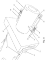
- FIG 1 illustrates a sound neutralizer device for a firearm in one embodiment of the invention.
- two closing shutters (10) are mounted transversely to the axis on the barrel of the weapon to temporarily close the barrel after the passage of a projectile and prevent the passage of combustion gases and sound probe towards the muzzle of the gun.
- barrel (42) when a shot is fired.
- the closing flaps (10) are arranged in a seat (37) placed transversely to the axis of the barrel and are of predetermined length and slightly offset from one another along the axis of the barrel, so that in the closed position they partially overlap. without clashing.
- the control mechanism (6) comprises two amplitude lever arms (8) mounted on pivots (7) to allow transverse movement of the two closing shutters (10) between an open position in which the shutters (10) ensure the passage of a projectile towards the muzzle and a closed position preventing the passage of combustion gases and the sound wave after the passage of the projectile.
- the exhaust unit (11) has two exhaust pipes (11) arranged upstream of the closing flaps (10) to redirect and allow the combustion gases and the sound wave to escape out of the barrel (42). .
- the control mechanism (6) is positioned upstream of the flaps (10).
- the control mechanism (6) operates the amplitude lever arms (8) which close the flaps (10), thus allowing the gases to escape through the pipes (11).
- the flaps (10) (and their seat 37) are placed transversely to the axis of the barrel (42) and are of predetermined length and slightly offset from one another along the axis of the barrel, so that in the closed position they partially overlap without s 'clash.
- each flap (10) has an opening adapted to receive the end of the amplitude lever arm (8) to transmit the pivoting movement of the amplitude lever (8) and actuate the flap (10) in a direction transverse to the axis of the barrel (42).
- the element (6) of the actuating mechanism is set in motion in a direction generally parallel to the axis of the barrel (42).
- control mechanism (6) comprises a guide ring (6) adapted to slide on the barrel and connected to the rod of the movable part of the barrel (31) to transmit the movement to the lever arms (8).
- the guide ring (6) further comprises two base pieces arranged laterally to the axis of the barrel (42) each forming an elongated opening to receive the end of one of the lever arms (8) and comprising a surface angle guide (rectilinear or curvilinear) directed towards the shutters (10) adapted to allow actuation of the lever arms (8) in pivoting on the pivots (7) to close and open the shutters (10).
- a surface angle guide rectilinear or curvilinear
- the guide ring (6) comprises two wedge-shaped base pieces arranged laterally to the axis of the barrel (42) and comprising an angled ridge surface (rectilinear or curvilinear) directed towards the shutters (10) adapted to allow actuation of the lever arms (8) in pivoting on the pivots (7) to close and open the shutters (10).
- the whole mechanism can be protected by a cover for current use and to prevent damage in use with a firearm, but it will depend on the weapon and its components. Since the cover is not essential for proper operation, it is not described in further detail.
- the two flaps (10) close the barrel after the bullet has passed, so that the sound wave and the gases are redirected to an expansion vessel.
- a second pair of flaps can be used to close the barrel at the base in case of automatic or semi-automatic weapons.
- the control ring (6) is actuated by the passage of the projectile after the flaps in a small portion (31) of the barrel which is movable and connected to the control ring (6) by a rod.
- This part (31) of the barrel (of the same caliber as the latter) is placed after the flaps (10) at a distance from them equal to the length of the body of the projectile (without its possible point).
- This part (31) is mobile and moves about 0.5mm, which serves to close the flaps (10) immediately after the passage of the ball.
- the proportion of the amplitude levers depends on the caliber of the weapon, the maximum being 10 for a 12 caliber single-barrel or superimposed, 20 for a juxtaposed 12 caliber (lateral), because for this weapon we are obliged to have a single shutter (10).
- the repositioning to the normal position of the parts (31, 6, 8 and 10) is provided by a return spring (32).
- the control mechanism (6) comprises a transmission rod and the movable part (31) comprises a coupling assembly (34-36) for setting the control ring (6) in motion.
- All coupling (34-36) comprises a connection arm (34) fixed to the movable part (31) by a connection screw (35) and secured to the transmission rod by a bolt and nut (36).
- the elongated opening made in the transmission rod allows the axial adjustment of the position of the rod relative to the connection arm (34) and to the movable part (31) by tightening the nut (36).
- the transmission rod is positioned in a direction generally parallel to the axis of the barrel defining the direction of the projectile.
- the movable part (31) is actuated axially and allows the transmission of the movement to the control mechanism (6) by coupling to the coupling assembly (34-36) and to the transmission rod .
- the control mechanism (6) with the rod is associated with a return spring (32) arranged on a fixing anchor (33) to the barrel.
- the axial force on the part (31) falling, the rod and the control mechanism (6) return to their initial position thanks to the return spring (32).
- the addition is done either by screwing, welding, interlocking or by any other means.
- the part (31), as an extension of the barrel, is mobile, its beginning being located after the flaps (10) at an exact distance corresponding to the length of the body of the projectile.
- the projectile passing through it gives it an axial movement which activates the entire device and causes the complete and immediate closing of the shutters (10).
- the gases and the sound wave are therefore diverted by the exhaust (11) for their treatment.
- the projectile continues its course in the part (38) of the weapon, which is the extension of the barrel.
- the axial force produced on the part (31) by the projectile being far greater than the needs of the device, it can be reduced either by judiciously increasing the diameter of said part (31) which is in principle of the same caliber as the barrel, either by adding a spring (not shown) around the right part of the part (31) which goes into the part (38), or both. Note that the part (31) does not hit the part (38) which receives it at the end.
- the moving part (31) is median to the barrel.
- This movable part (31) forms the seal with the part of the barrel (42) coming out of the seats (37) of the flaps (10) and the end part (38) of the barrel.
- This movable part (31) is cylindrical and has an internal bore adapted to allow the passage of a ball.
- the interior of the barrel in which the projectile moves is divided into 3 parts (42,31, 38) which must be perfectly aligned.
- the cylindrical movable part (31) comprises a covering part and a covered part separated by a shoulder. In its covering cylindrical part, the movable part (31) covers the barrel (42), and in its covered cylindrical part it is covered by the final part (38) of the barrel.
- the length of the part of the barrel (42) which passes through the seat (37) of the flaps (10) has a fixed length which is equal to the length of a bullet for this type of weapon. If the part of the part (31) instead of being covered were covered, then it could move back inside the part (42) and thus prevent the shutters (10) from closing properly.
- the part (31) reproduces the part (42) which comes out of the shutters (10) and it in turn is covered.
- the part (38) which is grafted onto the seats (37) of the shutters (10) will contain the part (31) in its entirety ( figures 2 and 5 ).
- the final part (38) of the barrel comprises a housing comprising a first cylindrical part adapted to receive the part covering of the movable part (31) and a second cylindrical part of a smaller diameter adapted to receive the covered part of the movable part (31).
- the first cylindrical part and the second cylindrical part of the final part (38) are separated by a shoulder.
- the first cylindrical part of the final part (38) is longer than the covering cylindrical part of the movable part (31) to allow axial movement of the movable part (31).
- the second cylindrical part of the final part (38) can be of the same length as the covered cylindrical part of the movable part (31).
- the final part (38) of the barrel can be very short.
- the covering part of the movable part (31) has an inner diameter corresponding to the outer diameter of the part of the barrel (42) which passes through the seat (37), and has an outer diameter corresponding to the inner diameter of the first cylindrical part of the final part (38).
- the covered part of the movable part (31) has an inside diameter corresponding to the inside diameter of the part of the barrel (42) which passes through the seat (37), and has an outside diameter corresponding to the inside diameter of the second cylindrical part of the cylinder. final part (38).
- the assembly can in particular be done so that the device (31,37,38) is incorporated into the weapon during its manufacture.
- the seat (37) of the flaps (10) is fixed to part 38 of the weapon, which is the extension of the barrel.
- the straight part of the moving part (31) is inserted between the seat (37) and the part 38.
- the connecting arm (34) and the part (35) are added to the part 31 after assembly.
- the part (38) of the device as shown in figure 1 forms the end part (38) of the barrel and comprises a part provided for the assembly to the seat (37) of the flaps (10) and to receive the moving part (31).
- the alternative for shotguns is to use a mini-part (38) at the outer end of which we will screw a choke ( Figure 10 ) of the aforementioned type forming a constriction or constriction to be mounted on the barrel to reduce the outlet diameter, so as to increase the range of the shot and to limit the spray of shot.
- FIGS 8 , 12 and 9 show a moving part (31) mounted in the final part of the barrel. It is the same configuration for the balls as for the chokes. While for bullet guns part (31) will be cylindrical and quite short, for shotguns part (31) will have the shapes, configurations, and length of a traditional choke ( figure 10 ).
- the movable part (31) is terminal to the barrel.
- This movable part (31) is mounted on the part of the barrel (42) coming out of the seats (37) of the flaps (10).
- This mobile part (31) is cylindrical and has a bore interior adapted to allow the passage of a ball.
- the interior of the barrel in which the projectile moves is divided into two parts (42,31) which must be perfectly aligned.
- the cylindrical movable part (31) comprises a covering part and a final part separated by a shoulder. In its covering cylindrical part, the movable part (31) covers the barrel (42), and in its final cylindrical part it forms the muzzle of the barrel.
- the part (31) reproduces the part (42) which comes out of the shutters (10).
- the part (31) is grafted onto the part (42) which comes out of the shutters (10) ( figure 9 ).
- the covering part of the movable part (31) comprises a housing comprising a cylindrical part adapted to receive the cylindrical part of the final part (42) of the barrel and allow the axial movement of the movable part (31).
- the cylindrical part of the final part (42) can be of the same length as the covering cylindrical part of the movable part (31).
- the final part (38) of the barrel can be very short.
- the covering part of the movable part (31) has an inside diameter corresponding to the outside diameter of the part of the barrel (42) which passes through the seat (37).
- the specific dimensions recommended for the device added to the existing weapon may be as follows:
- the mobile part (31) is terminal to the barrel and forms a choke used in particular for shotguns, the choke forming a passage for the lead, which extends in the extension of the barrel and whose internal diameter is reduced to direction of the muzzle.
- the cylindrical movable part (31) comprises a covering part and a final part separated by a shoulder.
- the movable part (31) covers the barrel (42), and in its final part forming the muzzle of the barrel it comprises a conical part having a maximum diameter equal to the internal diameter of the barrel and narrowing towards the area of the outlet.
- the resistance of the part (31) to axial movement can be reinforced with return springs (40) interposed between an element (41) of the part (31) and a rod (39) fixed to the seat (37) of the flaps (10) to allow the part (31) to resist axial movement and regain its initial position.
- the version of the figure 11 is similar to Figures 8 , 12 , 9 and presents a reinforced version of the part (31) in the final position.
- the bullet length of shotguns roughly matches the length of the wad. This depends on the ammunition used and the length of the gun chamber. The length of the latter is 68mm (almost obsolete), 70mm, 76mm and 82mm.
- the length of a skirted wad for a 70mm ammunition is approximately 40mm. Part 6 provides an adjustment for adaptation.
- an expansion vessel with timer (22-27) is associated with the exhaust pipes (21) for the treatment of the recovered gases and the inhibition of the sound wave.
- Other solutions are possible.
- the expansion tank (27) is coupled to the exhaust pipes (21) and comprises an internal axis (23) driven by the gas pressure to redirect these gases.
- the expansion vessel 27 receives the gases conveyed by the recovery pipes (21) which enter the expansion vessel 20 27 through the opening (22) made on the axis (23) once the latter has been pushed to the end of the stroke and thus have closed the openings (24).
- a pressure relief valve (25) is present (but could be replaced by small holes). As the pressure drops, the axis returns to its initial position thanks to the return spring (26) and the gases are discharged through the vents (24).
- the final aim of the device achieved by the invention described here is the inhibition of the sound wave produced by the firing of the ammunition (rifle shot).
- This shutter intended to inhibit the sound wave produced by the firing of the ammunition (gun shot) prevents the escape of combustion gases and sound waves through the muzzle by deflecting them towards a treatment area adequate, while leaving intact the prerogatives specific to ammunition (speed, precision).
- the motricity of the device is ensured only by the passage of the ball in the part (31) which is mobile (displacement of the order of a maximum of one millimeter).
- the section of the barrel is very slightly smaller than the caliber of the bullet, this to ensure a lateral seal so as to make the best use of the gas pressure.
- the ball traveling from left to right in relation to the drawings - eg. Fig. 2 ) as soon as it has crossed the level of the flaps (10) to its full length, enters the movable part of the barrel (31) giving it an axial forward movement.
- the moving part (31) actuates the control ring (6) which, also moving from left to right, closes the shutter (s) (10) by means of the lever arms (8).
- the gases and the sound wave are thus deflected by the exhaust (s) (11).
- the parts (31, 6, 8 and 10) return to the initial position thanks to the return spring (32).
- the device is incorporated into the barrel during its manufacture (in which case the device is located well before the muzzle of the barrel, and therefore an end of the barrel is added after part (31), or part 38 ) - illustrated by the drawings ( Fig. 2 ) or the device is added to the end of the barrel on the muzzle side ( Fig. 8 ) as an extension of the existing or in place of part of the existing, after having shortened it accordingly.
- This addition can be done according to several methods: brazing, screwing, bayonet, etc.).
- the proportion of the amplitude arms depends directly on the caliber of the weapon: 1 to 4 for an 8 mm (bullet), 1 to 1 0 for a caliber 1 2 (shot), and will therefore be fixed.
- the closing mechanism consists of lever arms (8) actuated by a part (6) whose shape can be variable. Once the projectile has passed level with the flaps, they close directly behind and the gases are directed to one or two exhaust pipes leading to an expansion tank with timer. The gases conveyed by the recovery pipes (21) enter the expansion vessel through the opening (22) made on the shaft (23) once the latter has been pushed to the end of its travel and thus closed. the openings (24). A pressure relief valve (25) is present (but could be replaced by small holes). As the pressure drops, the axis returns to its initial position thanks to the spring (26) and the gases are discharged through the vents.
- the projectile enters a movable part of the barrel (31) by pushing it forward.
- the rod of this part (31) being connected to the ring (6) pulls the latter forward which has the consequence of actuating the lever arms (8) on the pins (7) which will close the shutters (10) , the gases being thus diverted to the exhaust (11), and then treated in the expansion vessel (27).
- this expansion vessel can have any shape and is made from any material, solid or elastic; it can be applied anywhere on the weapon (for example laterally on the barrel or below);
- the setting in motion of the entire device will be controlled by the thrust that the projectile exerts on the movable part of the barrel (31).
- the amplitude coefficient will be calculated according to the caliber so that the flaps close immediately after the passage of the projectile, letting it advance by less than a millimeter.
Landscapes
- Engineering & Computer Science (AREA)
- General Engineering & Computer Science (AREA)
- Exhaust Silencers (AREA)
- Toys (AREA)
- Pipe Accessories (AREA)
Description
La présente invention concerne un dispositif neutralisateur de son pour arme à feu, en particulier pour fusil ou une autre arme à feu longue ou courte et une méthode de neutralisation du son pour arme à feu.The present invention relates to a sound neutralizer device for a firearm, in particular a rifle or other long or short firearm, and a sound neutralization method for a firearm.
Selon un premier aspect, la présente invention concerne plus spécifiquement un neutralisateur de son pour arme à feu, telle qu'un fusil ou une autre arme à feu longue ou courte.According to a first aspect, the present invention relates more specifically to a sound neutralizer for a firearm, such as a rifle or other long or short firearm.
Selon un deuxième aspect, l'invention propose une méthode de neutralisation du son pour arme à feu, en particulier pour fusil ou une autre arme à feu lorsqu'un coup est tiré.According to a second aspect, the invention proposes a method of neutralizing the sound for a firearm, in particular for a rifle or another firearm when a shot is fired.
Selon un troisième aspect, l'invention propose une arme à feu, en particulier fusil, comprenant un dispositif amélioré neutralisateur de son.According to a third aspect, the invention provides a firearm, in particular a rifle, comprising an improved sound neutralizer device.
Concernant l'état de la technique antérieure, il existe le silencieux classique qui peut être ajouté à une arme à feu, à gaz ou à air, appelé aussi modérateur de son, qui tente de diminuer mécaniquement ce dernier.Regarding the state of the prior art, there is the conventional silencer which can be added to a firearm, gas or air, also called a sound moderator, which attempts to mechanically reduce the latter.
A titre d'exemple, la publication
Les publications
Un silencieux ou modérateur de son classique est un dispositif qui peut être ajouté à une arme à feu, à gaz ou à air, pour réduire le bruit et le flash lumineux qu'elle produit lorsqu'un coup est tiré, et ainsi gagner en discrétion.A classic silencer or sound moderator is a device that can be added to a firearm, gas or air, to reduce the noise and the flash of light it produces when a shot is fired, and thus gain stealth .
Pour ce faire, le silencieux prend généralement la forme d'un tube cylindrique pouvant s'adapter à la bouche du canon, et dont le mécanisme interne, qui varie en fonction des munitions utilisées, permet de détendre les gaz ayant servi à la propulsion du projectile, afin d'atténuer autant que possible leur libération dans l'atmosphère.To do this, the silencer generally takes the form of a cylindrical tube that can adapt to the muzzle of the barrel, and whose internal mechanism, which varies according to the ammunition used, allows the gases used to propel the gun to be relaxed. projectile, in order to attenuate as much as possible their release into the atmosphere.
Comme le silencieux ne fait que ralentir le gaz à la sortie du canon, il n'interfère pas sur le bruit causé par le passage du projectile en vitesse supersonique (vitesse supérieure à celle du son qui est d'environ 340 m/s dans l'air à 15 °C) qui, en passant le mur du son, produit lui-même un bruit de détonation sur son parcours. Le phénomène est surtout sensible sur les calibres à haute vitesse initiale tels que le 5,56 mm . Il existe pour certains calibres de cartouche, notamment pour les armes de poing, des munitions subsoniques créées spécifiquement pour être employées avec un silencieux, afin de minimiser le bruit du tir.As the silencer only slows down the gas at the exit of the barrel, it does not interfere with the noise caused by the passage of the projectile in supersonic speed (speed greater than that of sound which is about 340 m / s in the air at 15 ° C) which, by passing the sound barrier, itself produces a detonation noise on its path. The phenomenon is especially noticeable on high initial speed calibers such as the 5.56 mm. For certain calibers of cartridges, notably for handguns, there is subsonic ammunition created specifically for use with a silencer, in order to minimize the noise of the shot.
Un silencieux est surtout un outil de confort, car il réduit l'onde de bouche d'une arme à feu. Cette onde de bouche est la cause de traumatismes ORL, dans la zone du nez, de la gorge et des oreilles, que ne peuvent protéger les moyens habituels (bouchons auriculaires, casques de tir...).A silencer is primarily a tool of comfort, as it reduces the muzzle wave of a gun. This mouth wave is the cause of ENT trauma, in the area of the nose, throat and ears, which the usual means cannot protect (earplugs, shooting helmets, etc.).
Il faut noter que les deux principaux facteurs jouant sur la valeur de la vitesse du son sont la masse volumique et la constante d'élasticité (ou compressibilité) du milieu de propagation :
La propagation du son est d'autant plus rapide que la masse volumique du milieu et sa compressibilité sont petites. D'un milieu à l'autre, les deux paramètres changent. Dans l'hélium, dont la compressibilité est à peu près égale à celle de l'air, mais dont la masse volumique est, dans les mêmes conditions de température et de pression, bien 10 plus faible, la vitesse du son est presque trois fois plus grande que dans l'air. Dans un gaz à pression atmosphérique, la vitesse du son est bien plus faible que dans un liquide : bien que la masse volumique du gaz soit bien plus faible, celui-ci est presque infiniment plus compressible que le liquide (qui est souvent considéré incompressible).It should be noted that the two main factors affecting the value of the speed of sound are the density and the elasticity constant (or compressibility) of the propagation medium:
The propagation of sound is all the more rapid as the density of the medium and its compressibility are small. From one medium to another, the two parameters change. In helium, the compressibility of which is about equal to that of air, but whose density is, under the same conditions of temperature and pressure, much lower, the speed of sound is almost three times larger than in the air. In a gas at atmospheric pressure, the speed of sound is much lower than in a liquid: although the density of the gas is much lower, it is almost infinitely more compressible than liquid (which is often considered incompressible) .
Par exemple, le son se propage exactement à 1 482,343 m/s dans l'eau pure à 20 °C, approximativement à 340 m/s dans Pair à 15 °C et à environ 1 500 m/s dans l'eau de mer.For example, sound propagates at exactly 1,482.343 m / s in pure water at 20 ° C, approximately 340 m / s in air at 15 ° C, and about 1,500 m / s in sea water. .
L'efficacité des silencieux est relative : le réducteur de son supprime l'onde de bouche et par conséquent la détonation conséquente et rend le son plus diffus tout en supprimant la flamme à la bouche de l'arme. On emploie parfois le terme modérateur de son ; les performances de ce type de dispositif sont très variables, en fonction du type de réducteur de son employé et de Parme utilisée. Le tir s'entend moins loin, il est également plus difficile à identifier comme un tir d'arme à feu ainsi que plus difficile à localiser tant en raison de la déformation du son que de l'absence de flamme visible. La diminution de l'intensité du bruit est de l'ordre de 25 à 35 db dans le cas d'un fusil d'assaut, soit 115 à 125 db (comparable à un marteau-piqueur) au lieu de 150 db. Les silencieux classiques, tout en pouvant présenter des formes et des techniques différentes, sont malgré tout assez semblables entre eux, Il s'agit généralement de manchons que Pon fixe, soit par un système à baïonnette soit par un pas de vis fileté, au bout du canon.The effectiveness of the silencers is relative: the sound reducer suppresses the muzzle wave and consequently the consequent detonation and makes the sound more diffuse while suppressing the flame at the muzzle of the weapon. The term sound moderator is sometimes used; the performance of this type of device is very variable, depending on the type of reducer used by its employee and the Parma used. The shot is heard less far, it is also more difficult to identify as a gunshot as well as more difficult to locate both because of the distortion of the sound and the absence of visible flame. The reduction in noise intensity is of the order of 25 to 35 db in the case of an assault rifle, or 115 to 125 db (comparable to a jackhammer) instead of 150 db. The classic silencers, while being able to have different shapes and techniques, are despite everything quite similar to each other.They are generally sleeves that Pon fixes, either by a bayonet system or by a threaded screw thread, at the end of the barrel.
Ces manchons, d'une dimension conséquente, comportent à l'intérieur plusieurs chambres d'expansion des gaz qui permettent d'atténuer le bruit de la détonation avec plus ou moins de réussite. Le projectile, les gaz et l'onde sonore résiduelle sortent par la bouche.These sleeves, of a substantial size, have inside several gas expansion chambers which make it possible to attenuate the noise of the detonation with varying degrees of success. The projectile, the gases and the residual sound wave exit through the muzzle.
Leurs défauts sont : poids important (plusieurs centaines de grammes, voire plus d'un kilo), grandes dimensions, déséquilibre de l'arme (elle pique du nez), impossibilité de l'utiliser dans des armes à double canon ainsi que, la plupart du temps, avec des munitions à grenaille.Their faults are: heavy weight (several hundred grams, or even more than a kilo), large dimensions, imbalance of the weapon (it stings the nose), inability to use it in double-barreled weapons as well as the Most of the time, with shot ammunition.
Par ailleurs le diamètre des trous séparant les différents éléments du silencieux par lesquels passent les projectiles étant bien plus grand que le calibre, ils laissent échapper vers l'avant du projectile une partie des gaz perturbant ainsi la précision du projectile et en diminuant sa vitesse d'environ de 4 à 6 m/s.In addition, the diameter of the holes separating the various elements of the silencer through which the projectiles pass being much larger than the caliber, they allow part of the gases to escape towards the front of the projectile, thus disturbing the precision of the projectile and reducing its speed. 'about 4 to 6 m / s.
Le silencieux classique est coûteux, d'entretien difficile (pour le nettoyer il faut le démonter complètement composant par composant), et, pour certains modèles de carabine, sa durée de vie ne dépasse pas les 800 coups.The classic silencer is expensive, difficult to maintain (to clean it, it must be completely dismantled component by component), and, for certain models of rifle, its life does not exceed 800 rounds.
Le projectile en passant les différentes chicanes laisse les gaz derrière elle se détendre dans les alvéoles et par là réduire l'intensité de l'onde sonore.The projectile passing the various baffles lets the gases behind it relax in the alveoli and thereby reduce the intensity of the sound wave.
L'efficacité d'un tel silencieux réside en deux facteurs : ses dimensions (plus il est grand plus il amortit), et la distance qui le sépare de la chambre de combustion (plus il en est éloigné, plus il est efficace). Puisqu'il est situé au bout du canon, donc plus celui-ci est long, plus le silencieux sera efficace. Il n'aura d'ailleurs pratiquement aucun effet s'il est employé avec des armes au canon très court, à moins qu'il soit grandement surdimensionné.The effectiveness of such a silencer lies in two factors: its dimensions (the larger it is, the more it dampens), and the distance between it and the combustion chamber (the further it is, the more efficient it is). Since it is located at the end of the barrel, so the longer it is, the more effective the silencer will be. It will also have virtually no effect if used with very short barreled weapons, unless it is greatly oversized.
Sur ce type de silencieux la réduction du bruit est fonction de la dimension des chambres (alvéoles). Le bruit normalement produit par une détonation d'arme à feu est de l'ordre de 120 à 170 db. Ainsi un bruit brutal ou une exposition prolongée à un environnement sonore trop élevé (au-delà de 100 db) peut provoquer une altération temporaire ou définitive de l'ouïe.On this type of silencer, the noise reduction depends on the size of the chambers (cells). The noise normally produced by a firearm detonation is of the order of 120 to 170 db. Sudden noise or prolonged exposure to too high a sound environment (over 100 db) can cause temporary or permanent hearing impairment.
En outre, des difficultés de mise en oeuvre se présentent aussi notamment pour certains silencieux classiques ou qui ne sont pas assez efficaces pour réduire le bruit lorsqu'un coup est tiré avec l'arme ce qui pose des problèmes certains.In addition, implementation difficulties also arise in particular for certain conventional silencers or which are not efficient enough to reduce the noise when a shot is fired with the weapon, which poses certain problems.
Il est donc clair qu'on a besoin d'un système qui, dans une large mesure, permet de remédier aux insuffisances mentionnées ci-dessus que l'on a rencontrées dans la technique antérieure.It is therefore clear that there is a need for a system which, to a large extent, overcomes the above mentioned shortcomings which have been encountered in the prior art.
Un objet de l'invention est de fournir un dispositif amélioré neutralisateur de son pour arme à feu, en particulier pour fusil ou une autre arme à feu longue ou courte.An object of the invention is to provide an improved sound neutralizer device for a firearm, in particular a rifle or other long or short firearm.
Alors qu'un silencieux classique, appelé aussi modérateur de son, s'efforce de diminuer mécaniquement ce dernier, le but de la présente invention est donc de proposer un dispositif permettant d'éliminer et inhiber complètement le son produit lorsqu'un coup est tiré, en le laissant s'épuiser de façon naturelle et ainsi gagner en discrétion.While a conventional silencer, also called a sound moderator, strives to mechanically reduce the latter, the aim of the present invention is therefore to provide a device making it possible to eliminate and completely inhibit the sound produced when a shot is fired. , by letting it run out in a natural way and thus gain in discretion.
Ainsi, le but du dispositif est d'inhiber l'onde sonore (le bruit) généré par la munition d'une arme à feu.Thus, the purpose of the device is to inhibit the sound wave (noise) generated by the ammunition of a firearm.
Cet objectif est atteint, suivant l'invention, en ce que le dispositif neutralisateur de son pour arme à feu comprend les caractéristiques de la partie caractérisante de la revendication 1.This objective is achieved, according to the invention, in that the sound neutralizer device for a firearm comprises the characteristics of the characterizing part of claim 1.
Plus particulièrement, à cet effet, conformément à l'invention, ce but est atteint par le fait que le un dispositif neutralisateur de son du type précité comprend :
- un mécanisme à volet (10) comprenant au moins un volet (10) de fermeture monté transversalement à l'axe sur le canon (42) de l'arme à feu pour obturer temporairement le canon après le passage d'une munition et empêcher le passage des gaz de combustion et de l'onde sonore vers la bouche du canon lorsqu'un coup est tiré,
- une unité d'actionnement (31,34,35) comportant une partie mobile (31) disposée axialement sur le canon de l'arme à feu pour mettre en mouvement un mécanisme de commande (6), la partie mobile axialement (31) comportant un perçage intérieur adapté pour permettre le passage d'une munition,
- le mécanisme de commande (6) comportant au moins un bras de levier d'amplitude (8) monté à pivotement sur un pivot (7) fixé au canon, chaque bras de levier d'amplitude (8) étant accouplé respectivement à un volet (10) de fermeture,
- l'unité d'actionnement mobile (31,34,35) coopérant avec le mécanisme de commande (6) pour permettre un mouvement transversal dudit au moins un volet (10) de fermeture entre une position ouverte dans laquelle le mécanisme à volet (10) assure le passage de la munition vers la bouche du canon (42) et une position fermée empêchant le passage des gaz de combustion et de l'onde sonore après le passage de la munition, et
- une unité d'échappement (11, 21-27) comportant au moins un tuyau d'échappement (11, 21) disposé sur le canon en amont du mécanisme à volet (10) de fermeture pour rediriger et laisser les gaz de combustion et l'onde sonore s'évacuer hors du canon.
- a shutter mechanism (10) comprising at least one closing shutter (10) mounted transversely to the axis on the barrel (42) of the firearm to temporarily close the barrel after the passage of a munition and prevent the passage of the combustion gases and the sound wave towards the muzzle when a shot is fired,
- an actuation unit (31,34,35) comprising a movable part (31) disposed axially on the barrel of the firearm to set in motion a control mechanism (6), the axially movable part (31) comprising an internal bore adapted to allow the passage of a munition,
- the control mechanism (6) comprising at least one amplitude lever arm (8) pivotally mounted on a pivot (7) fixed to the barrel, each amplitude lever arm (8) being respectively coupled to a shutter ( 10) closing,
- the movable actuating unit (31,34,35) cooperating with the control mechanism (6) to allow transverse movement of said at least one closing shutter (10) between an open position in which the shutter mechanism (10 ) ensures the passage of the ammunition towards the muzzle (42) and a closed position preventing the passage of combustion gases and the sound wave after the passage of the ammunition, and
- an exhaust unit (11, 21-27) comprising at least one exhaust pipe (11, 21) disposed on the barrel upstream of the shutter mechanism (10) for closing to redirect and leave the combustion gases and the sound wave escape out of the barrel.
Ainsi, pour atteindre ce but, à l'aide du mécanisme à volet de fermeture on obture temporairement le canon juste après le passage du projectile et on redirige les gaz de combustion et l'onde sonore vers un vase d'expansion pour son traitement final.Thus, to achieve this goal, using the closing shutter mechanism, the barrel is temporarily closed just after the passage of the projectile and the combustion gases and the sound wave are redirected to an expansion vessel for its final treatment. .
Préférentiellement, dans une réalisation de l'invention, l'unité d'actionnement comporte une partie mobile (31) du canon, mue par le projectile dès que celui-ci ait entièrement franchi les volets et prolongée par une tige reliée à la bague de commande.Preferably, in one embodiment of the invention, the actuation unit comprises a movable part (31) of the barrel, moved by the projectile as soon as the latter has completely passed through the flaps and extended by a rod connected to the locking ring. ordered.
Selon l'invention, pour assurer la motricité de tout le système, on rend mobile une petite partie du canon. Cette partie peut être terminale ou médiane. Préférentiellement, au passage du projectile à travers la pièce mobile (31), elle est poussée axialement en avant dans la partie (38) du canon en aval par la pression des gaz à l'intérieur du canon. Le mouvement axial de la pièce mobile (31) provoque la fermeture des volets au moyen du couplage du bras de levier d'amplitude (8) au mécanisme à volet (10) de fermeture. En principe, dans les armes fabriquées directement avec le dispositif incorporé la pièce mobile sera médiane tout au moins sur les armes longues.According to the invention, to ensure the traction of the entire system, a small part of the barrel is made mobile. This part can be terminal or middle. Preferably, when the projectile passes through the moving part (31), it is pushed axially forward in the part (38) of the downstream barrel by the pressure of the gases inside the barrel. The axial movement of the movable part (31) causes the shutters to close by means of the coupling of the amplitude lever arm (8) to the shutter mechanism (10) for closing. In principle, in guns manufactured directly with the device incorporated, the moving part will be median at least on long guns.
Dans le cas ou la partie mobile est médiane, elle fait le joint avec la partie du canon sortant des sièges des volets et la partie terminale du canon.In the case where the moving part is median, it forms the seal with the part of the barrel emerging from the seats of the flaps and the end part of the barrel.
L'intérieur du canon (dans lequel se déplace le projectile) est décomposé en 3 parties parfaitement alignées.The inside of the barrel (in which the projectile moves) is broken down into 3 perfectly aligned parts.
Préférentiellement, la partie mobile pièce a une partie recouvrante et une partie recouvrée. Dans sa partie recouvrante , la partie mobile recouvre le canon , et dans sa partie recouvrée elle est recouverte par la partie finale du canon.
La longueur de la partie du canon qui traverse le siège des volets a en principe une longueur fixe qui est égale à la longueur de la balle.Preferably, the movable part part has a covering part and a covered part. In its covering part, the moving part covers the barrel, and in its covered part it is covered by the final part of the barrel.
The length of the part of the barrel which passes through the seat of the flaps has in principle a fixed length which is equal to the length of the bullet.
Dans sa partie recouvrée la pièce mobile reproduit la partie du canon qui sort des volets et elle à son tour recouverte. La pièce finale du canon qui vient se greffer sur les sièges des volets va contenir entièrement la pièce mobile. La partie finale du canon peut être très courte.In its covered part, the moving part reproduces the part of the barrel which comes out of the shutters and it in turn is covered. The final part of the barrel which is grafted onto the seats of the shutters will entirely contain the moving part. The final part of the barrel can be very short.
Dans le cas ou la partie mobile est terminale, cette pièce finale forme la bouche du canon. C'est la même configuration soit pour les armes à balles que pour les chokes. Alors que pour les armes à balles la partie mobile est préférentiellement cylindrique et assez courte, pour les armes à grenailles la partie mobile a préférentiellement les formes, les dessins, et la longueur d'un choke traditionnel.In the case where the mobile part is terminal, this final part forms the muzzle of the barrel. It is the same configuration for both bullet guns and chokes. While for bullet guns the mobile part is preferably cylindrical and quite short, for shotguns the mobile part preferably has the shapes, designs and length of a traditional choke.
Préférentiellement, le mécanisme de commande comporte une bague de guidage et de transmission adaptée pour glisser sur le canon, la bague coopérant avec la tige de la partie mobile du canon pour transmettre le mouvement aux bras de levier. Préférentiellement, le(s) volet(s) de fermeture est/sont disposé(s) dans un siège placé transversalement à l'axe du canon et de longueur prédéterminée et s'il y en a deux légèrement décalés entre eux suivant l'axe du canon, pour qu'en position fermée ils se recouvrent partiellement sans s'entrechoquer.Preferably, the control mechanism comprises a guide and transmission ring adapted to slide on the barrel, the ring cooperating with the rod of the movable part of the barrel to transmit the movement to the lever arms. Preferably, the closing flap (s) is / are arranged in a seat placed transversely to the axis of the barrel and of predetermined length and if there are two slightly offset from each other along the axis of the barrel, so that in the closed position they partially overlap without colliding.
Dans une réalisation de l'invention chaque volet comporte une ouverture adaptée pour recevoir l'extrémité du bras de levier d'amplitude pour transmettre le mouvement de pivotement du levier d'amplitude et actionner le volet dans une direction transversale par rapport à l'axe du canon.In one embodiment of the invention, each shutter has an opening adapted to receive the end of the amplitude lever arm to transmit the pivoting movement of the amplitude lever and to actuate the shutter in a direction transverse to the axis. of the barrel.
Préférentiellement, la bague de guidage comprend en outre deux pièces de support en forme de coin comportant une surface d'arête en angle dirigée vers les volets adaptée pour permettre l'actionnement les bras de levier en pivotement sur les pivots et la fermeture des volets .Preferably, the guide ring further comprises two wedge-shaped support pieces comprising an angled edge surface directed towards the flaps adapted to allow actuation of the lever arms in pivoting on the pivots and the closing of the flaps.
Dans une réalisation de l'invention, le mécanisme de commande comporte au moins un premier ressort de rappel associé à la bague de guidage pour qu'elle retrouve sa position initiale, la pression des gaz baissant.In one embodiment of the invention, the control mechanism comprises at least a first return spring associated with the guide ring so that it returns to its initial position, the gas pressure decreasing.
Dans une réalisation préférée de l'invention, l'unité d'échappement comprend en outre un vase d'expansion connecté au dit au moins un tuyau d'échappement pour recevoir les gaz véhiculés par ledit au moins un tuyau d'échappement, le vase d'expansion comportant des ouïes permettant de laisser les gaz de combustion s'évacuer hors du vase d'expansion .In a preferred embodiment of the invention, the exhaust unit further comprises an expansion vessel connected to said at least one exhaust pipe for receiving the gases conveyed by said at least one exhaust pipe, the vessel expansion chamber with vents allowing combustion gases to escape from the expansion vessel.
Préférentiellement, le vase d'expansion comprend un tube interne connecté à des volets adaptés pour obturer les ouïes , et dans lequel les gaz pénètrent dans le vase d'expansion par une ouverture pratiquée dans le tube interne une fois que celui-ci a été poussé à fin de course et a ainsi obturé des ouïes et, la pression baissant, le tube interne retrouve sa position initiale grâce a un ressort de rappel laissant ainsi les gaz de combustion s'évacuer hors du vase d'expansion par les ouïes lorsque fonde sonore s'est épuisée de manière naturelle.Preferably, the expansion vessel comprises an internal tube connected to flaps adapted to close the openings, and in which the gases enter the expansion vessel through an opening made in the internal tube once the latter has been pushed. at the end of the stroke and thus blocked the vents and, with the pressure lowering, the inner tube returns to its initial position thanks to a return spring, thus allowing the combustion gases to escape out of the expansion tank through the vents when sound melts exhausted herself naturally.
Dans une réalisation préférée de l'invention, la partie mobile de l'unité d'actionnement substantiellement cylindrique rejoint une partie du canon qui traverse le siège des volets de fermeture et une partie terminale du canon, et comporte une partie recouvrante et une partie recouvrée séparée par un épaulement, la partie cylindrique recouvrante étant adaptée pour recouvrir la partie du canon qui traverse le siège des volets , et la partie cylindrique recouvrée étant adaptée pour être recouverte par la partie terminale du canon.In a preferred embodiment of the invention, the movable part of the substantially cylindrical actuating unit joins a part of the barrel which passes through the seat of the closing flaps and an end part of the barrel, and comprises a covering part and a covered part. separated by a shoulder, the covering cylindrical part being adapted to cover the part of the barrel which passes through the seat of the flaps, and the covered cylindrical part being adapted to be covered by the end part of the barrel.
Préférentiellement, la partie finale du canon comprend un logement comportant une première partie cylindrique adaptée pour recevoir la partie recouvrante de la pièce mobile et une seconde partie cylindrique d'un diamètre plus petit adaptée pour recevoir la partie recouvrée de la pièce mobile , la première partie cylindrique et la seconde partie cylindrique de la partie terminale étant séparées par un épaulement.Preferably, the final part of the barrel comprises a housing comprising a first cylindrical part adapted to receive the covering part of the moving part and a second cylindrical part of a smaller diameter adapted to receive the covered part of the moving part, the first part cylindrical and the second cylindrical part of the end part being separated by a shoulder.
Préférentiellement, la première partie cylindrique de la partie terminale est plus longue que la partie cylindrique recouvrante de la pièce mobile pour permettre le mouvement axial de la pièce mobile , la seconde partie cylindrique de la partie terminale étant substantiellement de même longueur que la partie cylindrique recouvrée de la pièce mobile .Preferably, the first cylindrical part of the end part is longer than the covering cylindrical part of the movable part to allow axial movement of the movable part, the second cylindrical part of the end part being substantially of the same length as the covered cylindrical part. of the moving part.
Préférentiellement, la partie recouvrante de la pièce mobile a un diamètre intérieur correspondant au diamètre extérieur de la partie du canon qui traverse le siège , et a un diamètre extérieur correspondant au diamètre intérieur de la première partie cylindrique de la partie terminale .Preferably, the covering part of the moving part has an inside diameter corresponding to the outside diameter of the part of the barrel which passes through the seat, and has an outside diameter corresponding to the inside diameter of the first cylindrical part of the end part.
Dans une autre réalisation préférée de l'invention , la partie mobile de l'unité d'actionnement substantiellement cylindrique forme la partie terminale du canon et comporte une partie recouvrante et une partie finale séparée par un épaulement, la partie cylindrique recouvrante de la pièce mobile étant adaptée pour recouvrir une partie du canon qui traverse le siège des volets de fermeture , et la partie terminale formant la bouche du canon.
Préférentiellement, la partie recouvrante de la pièce mobile comprend un logement comportant une partie cylindrique adaptée pour recevoir la partie cylindrique du canon qui traverse le siège des volets et permettre le mouvement axial de la pièce mobile , la partie cylindrique du canon étant substantiellement de même longueur que la partie cylindrique recouvrante de la pièce mobile .In another preferred embodiment of the invention, the movable part of the substantially cylindrical actuating unit forms the end part of the barrel and comprises a covering part and a final part separated by a shoulder, the covering cylindrical part of the movable part. being adapted to cover a part of the barrel which passes through the seat of the closing flaps, and the end part forming the muzzle of the barrel.
Preferably, the covering part of the moving part comprises a housing comprising a cylindrical part adapted to receive the cylindrical part of the barrel which passes through the seat of the flaps and allow the axial movement of the movable part, the cylindrical part of the barrel being substantially of the same length as the covering cylindrical part of the movable part.
Préférentiellement, la partie recouvrante de la pièce mobile a un diamètre intérieur correspondant au diamètre extérieur de la partie du canon qui traverse le siège des volets.Preferably, the covering part of the moving part has an inside diameter corresponding to the outside diameter of the part of the barrel which passes through the seat of the flaps.
Préférentiellement, pour les armes à grenaille, la pièce mobile terminale au canon forme un choke dont le diamètre interne se réduit en direction de la bouche du canon, la partie cylindrique recouvrante recouvrant le canon , et la partie terminale comportant une partie conique interne d' un diamètre maximal égal au diamètre interne du canon et se rétrécissant vers la zone du débouché du canon.Preferably, for shotguns, the terminal movable part to the barrel forms a choke, the internal diameter of which is reduced towards the muzzle of the barrel, the covering cylindrical part covering the barrel, and the end part comprising an internal conical part of a maximum diameter equal to the internal diameter of the barrel and narrowing towards the area of the outlet of the barrel.
Dans une autre réalisation de l'invention (non-illustrée), une seconde paire de volets indépendants des premiers (ou un seul volet), est sise à la sortie de la chambre à cartouche, peut être posée sur des armes automatiques ou semi-automatiques; ces volets actionnés mécaniquement par le propre dispositif d'éjection/rechargement de l'arme servent à empêcher les gaz de combustion, Tonde sonore et le flash de sortir par la culasse ouverte lors de l'éjection de la douille. Cette variante utilisant une seconde paire de volets pour armes automatiques ou semi-automatiques peut être utilisée toute seule pour simple modification d'une arme sans recourir à l'inhibiteur de son qui, lui, demande au moins le remplacement ou la modification du canon.In another embodiment of the invention (not shown), a second pair of shutters independent of the first (or a single shutter), is located at the outlet of the cartridge chamber, can be placed on automatic or semi-automatic weapons. automatic; these flaps, which are mechanically actuated by the weapon's own ejection / reloading device, serve to prevent combustion gases, sound and the flash from exiting through the open breech when the cartridge is ejected. This variant using a second pair of shutters for automatic or semi-automatic weapons can be used alone for simple modification of a weapon without resorting to the sound inhibitor which, for its part, requires at least the replacement or modification of the barrel.
Dans une autre réalisation de l'invention, le dispositif neutralisateur de son pour arme à feu, en particulier pour fusil ou une autre arme à feu longue ou courte, comprend:
- au moins un volet de fermeture monté transversalement à l'axe sur le canon de l'arme à feu pour obturer temporairement le canon après le passage d'un projectile et empêcher le passage des gaz de combustion et de l'onde sonore vers la bouche du canon lorsqu'un coup est tiré,
- une unité d'actionnement comportant une partie mobile du canon en aval du volet de fermeture pour mettre en mouvement par le passage du projectile le mécanisme de commande ;
- le mécanisme de commande comportant au moins un bras de levier d'amplitude monté à pivotement sur un pivot fixé au canon, le bras de levier d'amplitude étant accouplé au volet de fermeture, l'unité d'actionnement coopérant avec le mécanisme de commande pour permettre un mouvement transversal du volet de fermeture entre une position ouverte dans laquelle le volet assure le passage d'une munition vers la bouche du canon et une position fermée empêchant le passage des gaz de combustion et de l'onde sonore après le passage du projectile, et une unité d'échappement comportant au moins un tuyau d'échappement disposé sur le canon en amont du volet de fermeture pour rediriger et laisser les gaz de combustion et l'onde sonore s'évacuer hors du canon.
- at least one closing flap mounted transversely to the axis on the barrel of the firearm to temporarily close the barrel after the passage of a projectile and prevent the passage of combustion gases and the sound wave towards the muzzle of the barrel when a shot is fired,
- an actuating unit comprising a movable part of the barrel downstream of the closing flap to set the control mechanism in motion by the passage of the projectile;
- the control mechanism comprising at least one amplitude lever arm mounted to pivot on a pivot fixed to the barrel, the amplitude lever arm being coupled to the closing flap, the actuating unit cooperating with the control mechanism to allow transverse movement of the closing flap between an open position in which the flap ensures the passage of an ammunition towards the muzzle of the barrel and a closed position preventing the passage of combustion gases and of the sound wave after the passage of the projectile, and an exhaust unit comprising at least one exhaust pipe disposed on the barrel upstream of the closing flap to redirect and allow the combustion gases and the sound wave to escape out of the barrel.
Selon un autre aspect, l'invention propose une arme à feu longue ou courte, en particulier fusil, comprenant un dispositif neutralisateur du type précité dans lequel le canon de l'arme à feu comprend un système de fixation formé par lesdits pivots et un siège disposé transversalement à l'axe du canon recevant ledit mécanisme à volet de fermeture pour fixer le dispositif neutralisateur au canon de manière amovible.According to another aspect, the invention provides a long or short firearm, in particular a rifle, comprising a neutralizer device of the aforementioned type in which the barrel of the firearm comprises a fixing system formed by said pivots and a seat arranged transversely to the axis of the barrel receiving said closing flap mechanism to fix the neutralizer device to the barrel in a removable manner.
A cet effet, selon un autre aspect, l'invention propose une méthode de neutralisation du son pour armé à feu, en particulier pour fusil ou une autre arme à feu lorsqu'un coup est tiré, la méthode comprenant les étapes de:
- obturer temporairement le canon après le passage d'un projectile et empêcher le passage des gaz de combustion et de l'onde sonore vers la bouche du canon lorsqu'un coup est tiré, par au moins un volet de fermeture monté transversalement à l'axe sur le canon de l'arme à feu,
- mettre en mouvement, par l'action du passage du projectile dans une portion de canon mobile un mécanisme de commande ;
- le mécanisme de commande comportant au moins un bras de levier d'amplitude monté à pivotement sur des pivots fixés au canon, le bras de levier d'amplitude étant accouplé respectivement à un volet de fermeture,
- générer, au moyen de l'unité d'actionnement et du mécanisme de commande, un mouvement transversal du volet de fermeture entre une position ouverte dans laquelle le volet assure le passage d'un projectile vers la bouche du canon et une position fermée empêchant le passage des gaz de combustion et de l'onde sonore après le passage du projectile, et
- rediriger et laisser les gaz de combustion et Ponde sonore s'évacuer hors du canon au moyen d'une unité d'échappement comportant au moins un tuyau d'échappement disposé sur le canon en amont du mécanisme à volet.
- temporarily block the barrel after the passage of a projectile and prevent the passage of combustion gases and the sound wave towards the muzzle of the barrel when a shot is fired, by at least one closing flap mounted transversely to the axis on the barrel of the firearm,
- set in motion, by the action of the passage of the projectile through a portion of the movable barrel, a control mechanism;
- the control mechanism comprising at least one amplitude lever arm pivotally mounted on pivots fixed to the barrel, the amplitude lever arm being respectively coupled to a closing flap,
- generate, by means of the actuating unit and the control mechanism, a transverse movement of the closing shutter between an open position in which the shutter ensures the passage of a projectile towards the muzzle of the barrel and a closed position preventing the passage of combustion gases and the sound wave after the passage of the projectile, and
- redirecting and allowing the combustion gases and the sound probe to escape out of the barrel by means of an exhaust unit comprising at least one exhaust pipe arranged on the barrel upstream of the shutter mechanism.
Ainsi, pour atteindre ce but, à l'aide de un ou plusieurs volets on obture temporairement le canon juste après le passage du projectile et on redirige les gaz de combustion et l'onde sonore vers un vase d'expansion pour son traitement final.Thus, to achieve this goal, using one or more shutters, the barrel is temporarily closed off just after the projectile has passed and the combustion gases and the sound wave are redirected to an expansion vessel for its final treatment.
Il y a en principe 3 ondes sonores qui sont générées par un coup de feu. Deux se produisent à l'intérieur du canon, et la dernière à l'extérieur.There are in principle 3 sound waves which are generated by a gunshot. Two occur inside the barrel, and the last one outside.
A l'intérieur du canon, la première onde sonore est celle produite par la combustion de la charge explosive. La seconde est le fameux « bang » produit par le projectile lors du franchissement du mur du son, ce qui est le cas pour environ 96% des munitions. Ce "bang" se produisant à l'intérieur du canon, n'est pas certain mais supposé, mais il est en revanche certain qu'il n'intervient jamais en dehors du canon. A l'oreille humaine, ces deux ondes sonores sont perçues comme un seul et unique bruit. La troisième se produit à la sortie du projectile du canon, comme un coup de fouet dans l'air. Celle - ci a une intensité de 72 à 80 db et ne peut en aucune manière être maîtrisée.Inside the barrel, the first sound wave is that produced by the combustion of the explosive charge. The second is the famous "bang" produced by the projectile when crossing the sound barrier, which is the case for approximately 96% of ammunition. This "bang" occurring inside the barrel, is not certain but supposed, but it is on the other hand certain that it never occurs outside the barrel. To the human ear, these two sound waves are perceived as a single sound. The third occurs at the exit of the projectile from the barrel, like a whip in the air. This has an intensity of 72 to 80 db and can in no way be controlled.
La combustion de la poudre dégage une chaleur immédiate de 2500 à 3000 degrés Celsius, ainsi que 2 - 2.5 grammes de gaz qui, non compressés, donnent un volume d'environ 1,12 m3.The combustion of the powder releases an immediate heat of 2500 to 3000 degrees Celsius, as well as 2 - 2.5 grams of gas which, uncompressed, gives a volume of approximately 1.12 m3.
L'onde sonore produite par la combustion et le bang, se déplace (à cette température) à environ 1500-1800m/s, vitesse immédiate, alors que le projectile est encore en phase d'accélération, celui-ci n'atteignant sa vitesse maximum qu'après environ 60 cm de course.The sound wave produced by the combustion and the bang, moves (at this temperature) at about 1500-1800m / s, immediate speed, while the projectile is still in acceleration phase, it does not reach its speed maximum only after about 60 cm of travel.
Suivant l'invention, l'onde sonore a trois propriétés qui nous intéressent : la première c'est que, quand elle rencontre un obstacle, elle rebondit (phénomène écho), la seconde c'est qu'elle ne se propage pas dans le vide, et la troisième et plus intéressante pour le dispositif neutralisateur de son de la présente invention nous est qu'elle a une vie éphémère. On ne peut pas stocker de quelque manière qui soit une onde sonore : en l'empêchant de se propager elle disparaît.According to the invention, the sound wave has three properties which interest us: the first is that, when it encounters an obstacle, it bounces (echo phenomenon), the second is that it does not propagate in the empty, and the third and more interesting for the sound neutralizer device of the present invention is that it has a fleeting life. We cannot store a sound wave in any way: by preventing it from spreading it disappears.
L'onde sonore ne colle pas au projectile, En le heurtant elle rebondit en arrière vers la culasse qui à son tour la renvoie en avant vers le projectile. Il s'ensuit alors des va et vient incessants entre ces deux obstacles jusqu'à la sortie du projectile par la bouche du canon, à une vitesse variable, dépendante de la température du milieu dans lequel elle évolue et de celle des gaz qui la véhiculent. A la sortie du canon l'onde sonore se propage alors dans l'air.The sound wave does not stick to the projectile. By striking it it bounces back towards the breech which in turn sends it forward towards the projectile. It then follows incessant back and forth between these two obstacles until the projectile exits through the muzzle of the barrel, at a variable speed, depending on the temperature of the medium in which it operates and that of the gases which convey it. . At the exit of the barrel the sound wave then propagates in the air.
Alors qu'un silencieux classique du type précité, appelé aussi modérateur de son, s'efforce de diminuer mécaniquement ce dernier, l'inhibiteur de son de la présente invention, en retenant le son un très court instant à l'intérieur du canon, le laisse s'épuiser complètement de façon naturelle et arrive a l'éliminer complètement.While a conventional silencer of the aforementioned type, also called a sound moderator, tries to mechanically reduce the latter, the sound inhibitor of the present invention, by retaining the sound for a very short time inside the barrel, leaves it to exhaust itself completely in a natural way and manages to eliminate it completely.
En outre, le dispositif neutralisateur de son pour arme à feu de la présente invention a l'avantage du poids (environ 50 gr au total), du coût de fabrication, et de l'efficacité. Suivant l'invention, l'onde sonore produite à l'intérieur du canon est complètement annihilée, car retenue derrière le(s) volet(s).Further, the firearm sound neutralizer device of the present invention has the advantage of weight (about 50 grams in total), cost of manufacture, and efficiency. According to the invention, the sound wave produced inside the barrel is completely annihilated, because it is retained behind the shutter (s).
Reste donc uniquement le bruit produit par l'onde sonore générée hors du canon.So only the noise produced by the sound wave generated outside the barrel remains.
En fait, le dispositif neutralisateur de son pour arme à feu de la présente invention laisse l'onde sonore se détruire naturellement et traite surtout la pression générée par les gaz. S'il n'y avait pas d'échappement prévu par un tuyau d'échappement les gaz resteraient compressés à l'intérieur du canon maintenant le(s) volet(s) fermé(s). Ils se détendraient uniquement à l'ouverture du fusil, sans danger mais avec quelques désagréments.In fact, the firearm sound neutralizer device of the present invention allows the sound wave to destroy itself naturally and mostly deals with the pressure generated by the gases. If there was no exhaust provided by an exhaust pipe, the gases would remain compressed inside the barrel, keeping the shutter (s) closed. They would relax only when the gun was opened, safe but with some inconvenience.
Selon l'invention, il a été jugé préférable d'augmenter, par un ou deux tuyaux d'échappement le volume intérieur du canon. Ce volume supplémentaire fait baisser la pression des gaz et laisse le(s) volet(s) s'ouvrir par le système des ressorts derappel et laisse les gaz s'échapper naturellement à la foi vers l'avant et par le bout de l'échappement temporairement fermé par des volets de dimension semblable à ceux posés sur le canon. La baisse de pression des gaz à l'intérieur du canon est aussi provoquée par leur refroidissement rapide.According to the invention, it has been judged preferable to increase, by one or two exhaust pipes, the internal volume of the barrel. This additional volume lowers the gas pressure and allows the shutter (s) to open by the system of recoil springs and allows the gases to escape naturally forward and through the end of the escapement temporarily closed by shutters similar in size to those placed on the barrel. The drop in gas pressure inside the barrel is also caused by their rapid cooling.
D'autres caractéristiques et avantages de l'invention apparaîtront à la lecture de la description détaillée qui suit. Aussi, afin de permettre une compréhension plus claire de l'invention on décrira ci-après, plusieurs formes de réalisation préférées, à titre d'exemple, en se référant en particulier aux figures en annexe, parmi lesquelles :
- la
figure 1 illustre un dispositif neutralisateur de son pour arme à feu dans une réalisation de l'invention, - la
figure 2 représente une vue latérale partielle en coupe du dispositif tel que représenté dans lafigure 1 , - la
figure 3 représente une vue latérale avant assemblage du dispositif tel que représenté dans lafigure 1 , - la
figure 4 représente une vue latérale partielle de la pièce 38 du dispositif tel que représenté dans lafigure 1 , - la
figure 5 représente une vue latérale partielle en coupe de la pièce 38 du dispositif tel que représenté dans lafigure 1 , - la
figure 6 représente une vue latérale partielle du dispositif tel que représenté dans lafigure 1 , - la
figure 7 représente une vue latérale partielle du dispositif tel que représenté dans lafigure 1 , - la
figure 8 illustre un dispositif neutralisateur de son pour arme à feu dans une autre réalisation de l'invention, - la
figure 9 représente une vue latérale partielle en coupe du dispositif tel que, représenté dans lafigure 8 , - la
figure 10 représente une vue latérale partielle en coupe du dispositif tel que représenté dans lafigure 8 , - la
figure 11 illustre un dispositif neutralisateur de son pour arme à feu dans une autre réalisation de l'invention, - la
figure 12 représente une vue latérale partielle du dispositif tel que représenté dans lafigure 11 , - la
figure 13 représente une vue latérale d'une unité d'échappement du dispositif neutralisateur de son pour arme à feu dans une réalisation de l'invention.
- the
figure 1 illustrates a sound neutralizer device for a firearm in one embodiment of the invention, - the
figure 2 shows a partial sectional side view of the device as shown infigure 1 , - the
figure 3 shows a side view before assembly of the device as shown infigure 1 , - the
figure 4 shows a partial side view ofpart 38 of the device as shown infigure 1 , - the
figure 5 shows a partial sectional side view ofpart 38 of the device as shown infigure 1 , - the
figure 6 shows a partial side view of the device as shown infigure 1 , - the
figure 7 shows a partial side view of the device as shown infigure 1 , - the
figure 8 illustrates a sound neutralizer device for a firearm in another embodiment of the invention, - the
figure 9 shows a partial sectional side view of the device as shown infigure 8 , - the
figure 10 shows a partial sectional side view of the device as shown infigure 8 , - the
figure 11 illustrates a sound neutralizer device for a firearm in another embodiment of the invention, - the
figure 12 shows a partial side view of the device as shown infigure 11 , - the
figure 13 shows a side view of an exhaust unit of the sound neutralizer device for a firearm in one embodiment of the invention.
La présente invention est décrite avec des réalisations particulières et des références à des figures mais l'invention n'est pas limitée par celles-ci. Les dessins ou figures décrits ne sont que schématiques et ne sont pas limitants.
La
Selon le mode de réalisation préféré illustré en
The
According to the preferred embodiment illustrated in
Les volets de fermeture (10) sont disposés dans un siège (37) placé transversalement à l'axe du canon et sont de longueur prédéterminée et légèrement décalés entre eux suivant l'axe du canon, pour qu'en position fermée ils se recouvrent partiellement sans s'entrechoquer.The closing flaps (10) are arranged in a seat (37) placed transversely to the axis of the barrel and are of predetermined length and slightly offset from one another along the axis of the barrel, so that in the closed position they partially overlap. without clashing.
Le mécanisme de commande (6) comporte deux bras de levier d'amplitude (8) montés sur des pivots (7) pour permettre un mouvement transversal des deux volets (10) de fermeture entre une position ouverte dans laquelle les volets (10) assurent le passage d'un projectile vers la bouche du canon et une position fermée empêchant le passage des gaz de combustion et de l'onde sonore après le passage du projectile.The control mechanism (6) comprises two amplitude lever arms (8) mounted on pivots (7) to allow transverse movement of the two closing shutters (10) between an open position in which the shutters (10) ensure the passage of a projectile towards the muzzle and a closed position preventing the passage of combustion gases and the sound wave after the passage of the projectile.
L' unité d'échappement (11) comporte deux tuyaux d'échappement (11) disposé en amont des volets (10) de fermeture pour rediriger et laisser les gaz de combustion et l'onde sonore s'évacuer hors du canon (42).The exhaust unit (11) has two exhaust pipes (11) arranged upstream of the closing flaps (10) to redirect and allow the combustion gases and the sound wave to escape out of the barrel (42). .
Le mécanisme de commande (6) est positionné en amont des volets (10).The control mechanism (6) is positioned upstream of the flaps (10).
Le mécanisme de commande (6) actionne les bras de leviers d'amplitude (8) qui ferment les volets (10), laissant ainsi les gaz s'évacuer par les tuyaux (11). Les volets (10) (et leur siège 37) sont placés transversalement à l'axe du canon (42) et sont de longueur prédéterminée et légèrement décalés entre eux suivant Paxe du canon, pour qu'en position fermée ils se recouvrent partiellement sans s'entrechoquer.The control mechanism (6) operates the amplitude lever arms (8) which close the flaps (10), thus allowing the gases to escape through the pipes (11). The flaps (10) (and their seat 37) are placed transversely to the axis of the barrel (42) and are of predetermined length and slightly offset from one another along the axis of the barrel, so that in the closed position they partially overlap without s 'clash.
Avantageusement, chaque volet (10) comporte une ouverture adaptée pour recevoir l'extrémité du bras de levier d'amplitude (8) pour transmettre le mouvement de pivotement du levier d'amplitude (8) et actionner le volet (10) dans une direction transversale par rapport à l'axe du canon (42). L'élément (6) du mécanisme d'actionnement est mis en mouvement dans une direction généralement parallèle à l'axe du canon (42).Advantageously, each flap (10) has an opening adapted to receive the end of the amplitude lever arm (8) to transmit the pivoting movement of the amplitude lever (8) and actuate the flap (10) in a direction transverse to the axis of the barrel (42). The element (6) of the actuating mechanism is set in motion in a direction generally parallel to the axis of the barrel (42).
Préférentiellement, le mécanisme de commande (6) comporte une bague (6) de guidage adaptée pour glisser sur le canon et reliée à la tige de la partie mobile du canon (31) pour transmettre le mouvement aux les bras de levier (8) .Preferably, the control mechanism (6) comprises a guide ring (6) adapted to slide on the barrel and connected to the rod of the movable part of the barrel (31) to transmit the movement to the lever arms (8).
Avantageusement, comme on peut le voir par exemple en
Alternativement, dans un mode de réalisation non-illustré, la bague (6) de guidage comporte deux pièces de base en forme de coin disposées latéralement à l'axe du canon (42) et comportant une surface d'arête en angle (rectiligne ou curviligne) dirigée vers les volets (10) adaptée pour permettre d'actionner les bras de levier (8) en pivotement sur les pivots (7) pour fermer et ouvrir les volets (10).Alternatively, in a non-illustrated embodiment, the guide ring (6) comprises two wedge-shaped base pieces arranged laterally to the axis of the barrel (42) and comprising an angled ridge surface (rectilinear or curvilinear) directed towards the shutters (10) adapted to allow actuation of the lever arms (8) in pivoting on the pivots (7) to close and open the shutters (10).
Le passage du projectile dans la partie mobile du canon (31) pousse cette dernière en avant tirant ainsi, au moyen de la tige, la bague (6) en lui transmettant le mouvement, ce qui permet à cette bague d'actionner les bras de levier (8) sur les pivots (7) qui ferment les volets (10), les gaz étant ainsi déviés vers l'échappement (11).The passage of the projectile in the movable part of the barrel (31) pushes the latter forward thus pulling, by means of the rod, the ring (6) by transmitting the movement to it, which allows this ring to actuate the arms of lever (8) on the pivots (7) which close the flaps (10), the gases being thus diverted towards the exhaust (11).
Tout le mécanisme pourra être protégé par un capot pour une utilisation courante et éviter l'endommagement en utilisation avec une arme à feu, mais il dépendra de l'arme et de ses composants. Puisque le capot n'est pas indispensable au bon 5 fonctionnement, il n'est décrit plus en détail.The whole mechanism can be protected by a cover for current use and to prevent damage in use with a firearm, but it will depend on the weapon and its components. Since the cover is not essential for proper operation, it is not described in further detail.
Les deux volets (10) ferment le canon après le passage de la balle, de sorte que l'onde sonore et les gaz sont redirigés vers un vase d'expansion. Une seconde paire de volets peut être employée pour fermer le canon à la base en cas d'armes automatiques ou semi-automatiques. La bague (6) de commande est actionnée par le passage du projectile après les volets dans une petite portion (31) de canon qui elle est mobile et reliée à la bague de commande (6) par une tige . Cette partie (31) du canon (de même calibre que ce dernier) est placée après les volets (10) à une distance de ceux-ci égale à la longueur du corps du projectile (sans sa pointe éventuelle). Cette pièce (31) est mobile et bouge d'environ 0.5mm, ce qui sert à fermer les volets (10) immédiatement après le passage de la balle. La proportion des leviers d'amplitude est en fonction du calibre de l'arme, le maximum étant de 10 pour un calibre 12 mono-canon ou superposé, de 20 pour un calibre 12 juxtaposé (latéral), car pour cette arme on est obligé d'avoir un seul volet (10). Le repositionnement à la position normale des pièces (31 , 6, 8 et 10) est assuré par un ressort de rappel (32).The two flaps (10) close the barrel after the bullet has passed, so that the sound wave and the gases are redirected to an expansion vessel. A second pair of flaps can be used to close the barrel at the base in case of automatic or semi-automatic weapons. The control ring (6) is actuated by the passage of the projectile after the flaps in a small portion (31) of the barrel which is movable and connected to the control ring (6) by a rod. This part (31) of the barrel (of the same caliber as the latter) is placed after the flaps (10) at a distance from them equal to the length of the body of the projectile (without its possible point). This part (31) is mobile and moves about 0.5mm, which serves to close the flaps (10) immediately after the passage of the ball. The proportion of the amplitude levers depends on the caliber of the weapon, the maximum being 10 for a 12 caliber single-barrel or superimposed, 20 for a juxtaposed 12 caliber (lateral), because for this weapon we are obliged to have a single shutter (10). The repositioning to the normal position of the parts (31, 6, 8 and 10) is provided by a return spring (32).
Comme on peut le voir en
Comme on peut le voir plus en détail en
La tige de transmission est positionnée dans une direction généralement parallèle à l'axe du canon définissant la direction du projectile. Au passage du projectile à un point défini, la partie mobile (31) est actionnée axialement et permet la transmission du mouvement au mécanisme de commande (6) par accouplement à l'ensemble de couplage (34-36) et à la tige de transmission.The transmission rod is positioned in a direction generally parallel to the axis of the barrel defining the direction of the projectile. When the projectile passes at a defined point, the movable part (31) is actuated axially and allows the transmission of the movement to the control mechanism (6) by coupling to the coupling assembly (34-36) and to the transmission rod .
Le mécanisme de commande (6) avec la tige est associé à ressort de rappel (32) disposé sur un ancrage de fixation (33) au canon. La force axiale sur la pièce (31) baissant, la tige et le mécanisme de commande (6) retrouve sa position initiale grâce au ressort de rappel (32).The control mechanism (6) with the rod is associated with a return spring (32) arranged on a fixing anchor (33) to the barrel. The axial force on the part (31) falling, the rod and the control mechanism (6) return to their initial position thanks to the return spring (32).
Dans cette version, on peut soit avoir le dispositif incorporé dans l'arme à sa fabrication, soit ajouté à une arme existante en prolongements du ou des canons tels qu'ils existent, soit en prolongement du ou des canons après un raccourcissement de ces derniers. L'ajout ce fait soit par vissage, soudage, emboîtement soit par n'importe quel autre moyen.In this version, we can either have the device incorporated into the weapon during its manufacture, or added to an existing weapon as an extension of the barrel (s) as they exist, or as an extension of the barrel (s) after a shortening of the latter. . The addition is done either by screwing, welding, interlocking or by any other means.
Dans le cas ou le dispositif est incorporé dans l'arme , comme on peut le voir en
La force axiale produite sur la pièce (31) par le projectile étant de loin supérieure aux besoins du dispositif on peut la réduire soit en augmentant de manière judicieuse le diamètre de ladite pièce (31) qui est en principe du même calibre que le canon, soit en ajoutant un ressort (non illustré) autour de la partie droite de la pièce (31) qui rentre dans la pièce (38), soit les deux.
A noter que la pièce (31) ne percute pas au bout la pièce (38) qui la reçoit.In the case where the device is incorporated in the weapon, as can be seen in
The axial force produced on the part (31) by the projectile being far greater than the needs of the device, it can be reduced either by judiciously increasing the diameter of said part (31) which is in principle of the same caliber as the barrel, either by adding a spring (not shown) around the right part of the part (31) which goes into the part (38), or both.
Note that the part (31) does not hit the part (38) which receives it at the end.
Comme le montre la
La pièce mobile cylindrique (31) comporte une partie recouvrante et une partie recouvrée séparée par un épaulement.
Dans sa partie cylindrique recouvrante , la pièce mobile (31) recouvre le canon (42), et dans sa partie cylindrique recouvrée elle est recouverte par la partie finale (38) du canon.
La longueur de la partie du canon (42) qui traverse le siège (37) des volets (10) a une longueur fixe qui est égale à la longueur d'une balle pour ce type d'arme. Si la partie de la pièce (31) au lieu d'être recouvrante était recouverte, elle pourrait alors reculer à l'intérieur de la partie (42) et partant, empêcher les volets (10) de se fermer correctement.As shown in the
The cylindrical movable part (31) comprises a covering part and a covered part separated by a shoulder.
In its covering cylindrical part, the movable part (31) covers the barrel (42), and in its covered cylindrical part it is covered by the final part (38) of the barrel.
The length of the part of the barrel (42) which passes through the seat (37) of the flaps (10) has a fixed length which is equal to the length of a bullet for this type of weapon. If the part of the part (31) instead of being covered were covered, then it could move back inside the part (42) and thus prevent the shutters (10) from closing properly.
Dans sa partie recouvrée, la pièce (31) reproduit la partie (42) qui sort des volets (10) et elle à son tour recouverte. La pièce (38) qui vient se greffer sur les sièges (37) des volets (10) va contenir la pièce (31) dans son entier (
Comme le montre les
La première partie cylindrique de la partie finale (38) est plus longue que la partie cylindrique recouvrante de la pièce mobile (31) pour permettre le mouvement axial de la pièce mobile (31). La seconde partie cylindrique de la partie finale (38) peut être de même longueur que la partie cylindrique recouvrée de la pièce mobile (31). La partie finale (38) du canon peut être très courte.The first cylindrical part of the final part (38) is longer than the covering cylindrical part of the movable part (31) to allow axial movement of the movable part (31). The second cylindrical part of the final part (38) can be of the same length as the covered cylindrical part of the movable part (31). The final part (38) of the barrel can be very short.
La partie recouvrante de la pièce mobile (31) a un diamètre intérieur correspondant au diamètre extérieur de la partie du canon (42) qui traverse le siège (37), et a un diamètre extérieur correspondant au diamètre intérieur de la première partie cylindrique de la partie finale (38).The covering part of the movable part (31) has an inner diameter corresponding to the outer diameter of the part of the barrel (42) which passes through the seat (37), and has an outer diameter corresponding to the inner diameter of the first cylindrical part of the final part (38).
La partie recouvrée de la pièce mobile (31) a un diamètre intérieur correspondant au diamètre intérieur de la partie du canon (42) qui traverse le siège (37), et a un diamètre extérieur correspondant au diamètre intérieur de la seconde partie cylindrique de la partie finale (38).The covered part of the movable part (31) has an inside diameter corresponding to the inside diameter of the part of the barrel (42) which passes through the seat (37), and has an outside diameter corresponding to the inside diameter of the second cylindrical part of the cylinder. final part (38).
Comme on peut le voir en
Le siège (37) des volets (10) est fixé à la partie 38 de l'arme, qui est le prolongement du canon. La partie droite de la pièce mobile (31) est insérée entre le siège (37) et la pièce 38. Le bras de raccord (34) et la pièce (35) sont ajoutés à la pièce 31 après assemblage.As can be seen in
The seat (37) of the flaps (10) is fixed to
Comme on peut le voir en
A titre d'exemple, dans le cas d'une Carabine calibre 30 Blaser, en se référant en particulier aux
- Diamètre du projectile : 7.85 mmProjectile diameter: 7.85 mm
- Diamètre interne du canon haut des rainures : 7.6 mmInternal diameter of the barrel top of the grooves: 7.6 mm
- Diamètre externe du canon 15 mmExternal diameter of the barrel 15 mm
- Longueur corps balle (sans la partie pointue) : 20 mmBall body length (without the pointed part): 20 mm
- Longueur : 20 mmLength: 20mm
- Diamètre intérieur 7.6 mmInternal diameter 7.6 mm
- Diamètre extérieur : 10 mmExternal diameter: 10 mm
-
Longueur totale 24 mm
Total length 24 mm
- Longueur : 20 mmLength: 20mm
- Diamètre extérieur : 12 mmOutside diameter: 12 mm
- Diamètre intérieur : 10,2 mmInner diameter: 10.2 mm
- Longueur : 4 mmLength: 4mm
- Diamètre extérieur : 10,2 mmOuter diameter: 10.2 mm
- Diamètre intérieur : 7.6 mmInner diameter: 7.6 mm
- Diamètre extérieur : 15 mm (longueur indifférente)External diameter: 15 mm (any length)
-
Diamètre intérieur première partie: 12,2 mm sur 23 mm de longueur (la pièce 31 aura ainsi 3 mm de battement)Internal diameter first part: 12.2 mm by 23 mm in length (
part 31 will thus have 3 mm of beating) - Diamètre intérieur seconde partie : 10,2 mm sur 4 mm de longueurSecond part internal diameter: 10.2 mm over 4 mm long
- Diamètre intérieur partie finale : 7.6 mm jusqu'au boutInternal diameter final part: 7.6 mm to the end
Dans le cas ou le dispositif est ajouté aux armes existantes il faut faire une différence entre les armes à balles et les armes à grenaille.In the event that the device is added to existing weapons, a distinction must be made between bullet weapons and shotguns.
En effet, sur les armes à balles le calibre du canon est le même sur toute sa longueur alors que sur la plupart des fusils à grenaille le canon se termine par un rétrécissement appelé choke, de dimensions différentes selon la performance recherchée.In fact, on bullet guns the caliber of the barrel is the same over its entire length, while on most shotguns the barrel ends in a narrowing called choke, of different dimensions depending on the desired performance.
Sur les armes à grenaille il est bien connu que lors du tir d'une cartouche, l'impact du plomb présente une certaine dispersion qui augmente de manière proportionnelle à la distance à laquelle a lieu l'impact. Cette dispersion peut être influencée par l'utilisation de ce que l'on appelle un choke. En particulier, divers types de chokes ou étranglements à monter sur les canons de fusil pour diminuer leur diamètre de sortie, de façon à augmenter la portée du tir et à limiter la gerbe de plombs projetée.On shotguns it is well known that when firing a cartridge, the impact of the lead exhibits a certain dispersion which increases in proportion to the distance at which the impact takes place. This dispersion can be influenced by the use of what is called a choke. In particular, various types of chokes or chokes to be mounted on rifle barrels in order to reduce their outlet diameter, so as to increase the range of the shot and to limit the spray of pellets projected.
Il est donc clair que, d'une part, il faut garder sur ces armes la possibilité de choisir le choke adéquat, et d'autre part il y aura, si on utilise une seule pièce finale, une augmentation de la force axiale sur cette pièce.It is therefore clear that, on the one hand, it is necessary to keep on these weapons the possibility of choosing the adequate choke, and on the other hand there will be, if one uses a single final part, an increase in the axial force on this room.
Donc, pour les armes à balle on utilise la configuration comme sur les
L'alternative pour les armes à grenaille est d'utiliser une mini-pièce (38) au bout extérieur de laquelle on vissera un choke (
Les
Comme le montre les
La pièce mobile cylindrique (31) comporte une partie recouvrante et une partie finale séparée par un épaulement.
Dans sa partie cylindrique recouvrante , la pièce mobile (31) recouvre le canon (42), et dans sa partie cylindrique finale elle forme la bouche du canon.As shown by
The cylindrical movable part (31) comprises a covering part and a final part separated by a shoulder.
In its covering cylindrical part, the movable part (31) covers the barrel (42), and in its final cylindrical part it forms the muzzle of the barrel.
Dans sa partie finale, la pièce (31) reproduit la partie (42) qui sort des volets (10) .La pièce (31) vient se greffer sur la partie (42) qui sort des volets (10) (
Comme le montre la
La partie recouvrante de la pièce mobile (31) a un diamètre intérieur correspondant au diamètre extérieur de la partie du canon (42) qui traverse le siège (37).The covering part of the movable part (31) has an inside diameter corresponding to the outside diameter of the part of the barrel (42) which passes through the seat (37).
A titre d'exemple, dans le cas d'une Carabine calibre 30 Blaser, en se référant en particulier aux
- Diamètre du projectile : 7.85 mmProjectile diameter: 7.85 mm
- Diamètre interne du canon haut des rainures : 7.6 mmInternal diameter of the barrel top of the grooves: 7.6 mm
- Diamètre externe du canon 15 mmExternal diameter of the barrel 15 mm
- Longueur corps balle (sans la partie pointue) : 20 mmBall body length (without the pointed part): 20 mm
- Longueur : 20 mmLength: 20mm
- Diamètre intérieur 7.6 mmInternal diameter 7.6 mm
- Diamètre extérieur : 10 mmExternal diameter: 10 mm
-
Longueur totale 24 mm
Total length 24 mm - Diamètre extérieur 15 mmExternal diameter 15 mm
- Longueur : 20 mmLength: 20mm
- Diamètre intérieur : 10,2 mmInner diameter: 10.2 mm
- Longueur : 4 mm.Length: 4 mm.
- Diamètre intérieur : 7.6 mmInner diameter: 7.6 mm
Comme le montre la
Dans sa partie cylindrique recouvrante , la pièce mobile (31) recouvre le canon (42), et dans sa partie finale formant la bouche du canon elle comporte une partie conique ayant un diamètre maximal égal au diamètre interne du canon et se rétrécissant vers la zone du débouché.In its covering cylindrical part, the movable part (31) covers the barrel (42), and in its final part forming the muzzle of the barrel it comprises a conical part having a maximum diameter equal to the internal diameter of the barrel and narrowing towards the area of the outlet.
Comme le montre la
Il est à noter que la longueur de balle des fusils à grenaille correspond à peu près à la longueur de la bourre. Celle-ci est en fonction de la munition employée et de la longueur de la chambre du fusil. La longueur de ces dernières est de 68mm (quasiment obsolète), 70mm, 76mm et 82mm.Note that the bullet length of shotguns roughly matches the length of the wad. This depends on the ammunition used and the length of the gun chamber. The length of the latter is 68mm (almost obsolete), 70mm, 76mm and 82mm.
Il va de soi qu'une chambre plus longue peut utiliser des douilles plus courtes, le contraire étant en principe impossible et non recommandé. La longueur d'une bourre à jupe pour une munition de 70mm est d'environ 40mm. La pièce 6 prévoit un réglage pour adaptation.It goes without saying that a longer chamber can use shorter sockets, the opposite being in principle not possible and not recommended. The length of a skirted wad for a 70mm ammunition is approximately 40mm.
Une utilisation erronée des munitions, ou un disfonctionnement du dispositif peut créer des dommages. Dans nos essais, l'utilisation de volets de 2mm d'épaisseur en aluminium a donné d'excellents résultats. Des volets en aluminium intentionnellement laissés fermés lors du tir ont été traversé par les projectiles, même en grenaille, sans conséquence.Incorrect use of ammunition, or a malfunction of the device can create damage. In our tests, the use of 2mm thick aluminum shutters gave excellent results. Aluminum shutters intentionally left closed during firing were passed through by projectiles, even shot, without consequence.
Comme on peut le voir en
Selon le mode de réalisation illustré en
Le but final du dispositif atteint par l'invention ici décrite est l'inhibition de l'onde sonore produite par la mise à feu de la munition (coup de fusil).
Cet obturateur destiné à l'inhibition de l'onde sonore produite par la mise à feu de la munition (coup de fusil) empêche la sortie des gaz des combustion et des ondes sonores par la bouche du canon en les déviant vers une zone de traitement adéquate, tout en laissant intactes les prérogatives propres aux munitions (vitesse, précision).The final aim of the device achieved by the invention described here is the inhibition of the sound wave produced by the firing of the ammunition (rifle shot).
This shutter intended to inhibit the sound wave produced by the firing of the ammunition (gun shot) prevents the escape of combustion gases and sound waves through the muzzle by deflecting them towards a treatment area adequate, while leaving intact the prerogatives specific to ammunition (speed, precision).
- a) une onde sonore a une durée de vie éphémère ;
- b) elle ne peut être conservée ;
- c) elle est arrêtée par un obstacle quelconque (auquel cas elle rebondit- caisse de résonance), que celui-ci soit immobile ou en mouvement;
- d) elle ne se propage pas dans le vide;
- 1) La détonation produite par la déflagration ;
- 2) Le « bang » typique du mur du son lorsque celui est dépassé ;
- a) a sound wave has an ephemeral lifetime;
- b) it cannot be kept;
- c) it is stopped by any obstacle (in which case it bounces - resonance box), whether it is stationary or in motion;
- d) it does not propagate in a vacuum;
- 1) The detonation produced by the deflagration;
- 2) The typical “bang” of the sound barrier when it is exceeded;
Étant admis que la vitesse maximale d'un projectile est atteinte après 60 cm de course on pratique, après cette distance, une ouverture de dimensions adéquates pour rediriger les gaz et on incorpore au canon, juste après cette l'ouverture, un rail 25 transversal avec un volet gauche et un volet droit (ou inférieur et supérieur) chacun destiné à obturer la moitié transversale du canon par superposition. Les 2 volets sont actionnés par un levier d'amplitude. Le(s) levier(s) de chaque volet est mis en oeuvre par une commande mise en mouvement par le passage du projectile qui pousse en avant une partie mobile du canon.Given that the maximum speed of a projectile is reached after 60 cm of travel, after this distance, an opening of adequate dimensions to redirect the gases is made and a transverse rail is incorporated into the barrel, just after this opening. with a left flap and a right flap (or lower and upper) each intended to close off the transverse half of the barrel by superposition. The 2 flaps are actuated by an amplitude lever. The lever (s) of each flap is operated by a control set in motion by the passage of the projectile which pushes forward a movable part of the barrel.
Ceci est valable pour les armes dites longues ; pour les armes courtes la position du dispositif sera choisie en conséquence.This is valid for so-called long guns; for short weapons the position of the device will be chosen accordingly.
Le mécanisme se compose préférentiellement :
- i) D'une soupape de fermeture mécanique ou hydraulique a 1 volet (solide ou articulé) ou, de préférence à 2 volets juxtaposes (2 moitiés se recouvrant, meilleure solution car plus rapide), a diaphragme (genre obturateur photo), à couperet; rappel par ressort;
- ii) Dispositif de commande et motricité cinétique par la poussée du projectile
- iii) Un vase d'expansion étanche ;
- iv) Eventuellement d'un dispositif autonome pour la réinitialisation ;
- i) A mechanical or hydraulic closing valve with 1 shutter (solid or articulated) or, preferably with 2 juxtaposed shutters (2 halves overlapping, better solution because faster), with diaphragm (like shutter photo), with cleaver ; spring return;
- ii) Control device and kinetic traction by projectile thrust
- iii) A sealed expansion vessel;
- iv) Possibly a stand-alone device for the reset;
Les essais réalisés avec succès sont:
- A) neutralisation des gaz dans le vase d'expansion ;
- B) fermeture du canon après passage du projectile au moyen d'une soupape à volet ;
- i) un volet ou 2 volets de fermeture opposés sur 2 axes légèrement décalés, pour éviter l'entrechoquage ;
- ii) dispositif de commande (motricité cinétique par poussée du projectile) avec rappel par ressort ;
- m) mécanismes de levier d'amplitude de chaque coté ;
- iv) ouverture(s) pour rediriger les gaz ;
le facteur total d'amplitude développé par les leviers sera défini en fonction du calibre ;
Le bruit résiduel est celui provoqué par le projectile fouettant l'air.The successful tests are:
- A) neutralization of gases in the expansion vessel;
- B) closing of the barrel after passage of the projectile by means of a shutter valve;
- i) a shutter or 2 opposite closing shutters on 2 slightly offset axes, to avoid colliding;
- ii) control device (kinetic traction by thrust of the projectile) with spring return;
- m) amplitude lever mechanisms on each side;
- iv) opening (s) to redirect gas;
the total amplitude factor developed by the levers will be defined according to the caliber;
Residual noise is that caused by the projectile whipping the air.
Selon l'invention, la motricité du dispositif est assurée uniquement par le passage de la balle dans la pièce (31) qui est mobile (déplacement de l'ordre d'un millimètre max.).According to the invention, the motricity of the device is ensured only by the passage of the ball in the part (31) which is mobile (displacement of the order of a maximum of one millimeter).
Dans toutes les armes à feu la section du canon est très légèrement plus petite que le calibre de la balle, ceci pour assurer une étanchéité latérale de façon à exploiter au mieux la pression des gaz. Donc la balle, voyageant de gauche à droite par rapport aux dessins - par.ex.
Selon l'invention, soit on incorpore le dispositif dans le canon lors de sa fabrication (auquel cas le dispositif se trouve bien avant la bouche du canon, et donc on ajoute un bout du canon après la pièce (31), soit la pièce 38) - illustrée par les dessins (
Par ailleurs la proportion des bras d'amplitude dépend directement du calibre de l'arme: 1 à 4 pour un 8 mm (balle), 1 à 1 0 pour un calibre 1 2 (grenaille), et va donc être fixe.Moreover the proportion of the amplitude arms depends directly on the caliber of the weapon: 1 to 4 for an 8 mm (bullet), 1 to 1 0 for a caliber 1 2 (shot), and will therefore be fixed.
Le mécanisme de fermeture consiste à des bras de leviers (8) actionnés par une pièce (6) dont la forme peut être variable.
Une fois le projectile passé à la hauteur des volets, ceux-ci se ferment directement derrière et les gaz sont dirigés vers un ou deux tuyaux d'échappement conduisant à un vase d'expansion avec temporisateur. Les gaz véhiculés par les tuyaux de récupération (21) pénètrent dans le vase d'expansion par l'ouverture (22) pratiquée sur l'axe (23) une fois que celui-ci ait été poussé à fin de course et avoir ainsi obturé les ouvertures (24). Une soupape de surpression (25) est présente (mais pourrait être remplacée par des petits trous). La pression baissant, l'axe retrouve sa position initiale grâce au ressort (26) et les gaz s'évacuent par les ouies.The closing mechanism consists of lever arms (8) actuated by a part (6) whose shape can be variable.
Once the projectile has passed level with the flaps, they close directly behind and the gases are directed to one or two exhaust pipes leading to an expansion tank with timer. The gases conveyed by the recovery pipes (21) enter the expansion vessel through the opening (22) made on the shaft (23) once the latter has been pushed to the end of its travel and thus closed. the openings (24). A pressure relief valve (25) is present (but could be replaced by small holes). As the pressure drops, the axis returns to its initial position thanks to the spring (26) and the gases are discharged through the vents.
Une fois entièrement et à peine franchis les volets ouverts, le projectile pénètre dans une partie mobile du canon (31) en la poussant en avant. La tige de cette partie (31) étant reliée à la bague (6) tire celle-ci en avant ce qui a pour conséquence d'actionner les bras de levier (8) sur les pivots (7) qui fermeront les volets (10), les gaz étant ainsi déviés vers l'échappement (11), et traités ensuite dans le vase d'expansion (27).Once completely and barely passed the open shutters, the projectile enters a movable part of the barrel (31) by pushing it forward. The rod of this part (31) being connected to the ring (6) pulls the latter forward which has the consequence of actuating the lever arms (8) on the pins (7) which will close the shutters (10) , the gases being thus diverted to the exhaust (11), and then treated in the expansion vessel (27).
Selon une réalisation préférée de l'invention pour une arme à feu longue, il convient donc de:
Pratiquer des ouvertures d'échappement après 60 centimètres de course sur lesquelles viendra se greffer le vase d'expansion étanche et de dimension adéquate pour contenir les gaz de combustion; ce vase d'expansion (27) pourra avoir n'importe quelle forme et réalise dans n'importe quel matériau, solide ou élastique; il pourra être appliqué n'importe ou sur l'arme (par exemple latéralement sur la canon ou dessous) ;According to a preferred embodiment of the invention for a long firearm, it is therefore necessary to:
Make exhaust openings after 60 centimeters of travel to which the sealed expansion tank will be grafted and of adequate size to contain the combustion gases; this expansion vessel (27) can have any shape and is made from any material, solid or elastic; it can be applied anywhere on the weapon (for example laterally on the barrel or below);
Juste en aval de ces ouvertures on trouvera un support à volets (10) incorporé au canon lors de son processus de fabrication ou de modification de celui-ci; Le dispositif à volets sera actionné par tringlerie.Just downstream of these openings there will be a flap support (10) incorporated into the barrel during its manufacturing process or its modification; The shutter device will be actuated by linkage.
La mise en mouvement de tout le dispositif sera commandée par la poussée que le projectile exerce sur la partie mobile du canon (31).The setting in motion of the entire device will be controlled by the thrust that the projectile exerts on the movable part of the barrel (31).
On calculera le coefficient d'amplitude selon le calibre de manière que les volets ferment immédiatement après le passage du projectile le laissant avancer de moins d'un millimètre.The amplitude coefficient will be calculated according to the caliber so that the flaps close immediately after the passage of the projectile, letting it advance by less than a millimeter.
- 66
- Bague commandeCommand ring
- 77
- pivotspivots
- 88
- bras de levierslever arms
- 1010
- voletsshutters
- 10 1110 11
- tuyaux évacuationdrain pipes
- 3131
- partie mobilemoving part
- 3232
- ressort rappelspring return
- 3333
- ancrage ressortspring anchor
- 3434
- tige ou bras de raccordconnecting rod or arm
- 15 3515 35
- Vis de raccordConnection screw
- 3636
- boulon et écroubolt and nut
- 3737
- sièges voletsshutters seats
- 3838
- partie finale avec canonfinal part with cannon
- 3939
- tige de renfortreinforcement rod
- 20 4020 40
- ressort de rétentionretention spring
- 4141
- ancrage du renfortanchor reinforcement
- 4242
- canoncannon
- 2121
- jonction évacuationevacuation junction
- 2222
- ouverture sur axeopening on axis
- 25 2325 23
- axe et voletsaxis and flaps
- 2424
- ouvertures vasevase openings
- 2525
- soupape surpressionpressure relief valve
- 2626
- ressort rappelspring return
- 2727
- vase expansionexpansion vessel
Toutes les pièces, leur forme et leurs positions peuvent varier à l'infini. Les tuyaux de récupération ou d'échappement peuvent être réduits à un seul et pas forcément tubulaire, le vase d'expansion être de forme différente, la commande 6 représentée par une bague complète circulaire pourrait être en arc de cercle, etc.All parts, their shape and their positions can vary infinitely. The recovery or exhaust pipes can be reduced to one and not necessarily tubular, the expansion tank be of a different shape, the
La présente invention n'est en aucune manière limitée à la forme de réalisation décrite à titre d'exemple et représentée dans les figures. On pourra y apporter de nombreuses modifications de détails, de formes, et de dimensions sans sortir pour cela du cadre de l'invention tel que défini par les revendications annexées. La présente invention a été décrite en relation avec des modes de réalisations spécifiques, qui ont une valeur purement illustrative et ne doivent pas être considérés comme limitatifs. Les numéros de référence dans les revendications ne limitent pas leur portée.The present invention is in no way limited to the embodiment described by way of example and shown in the figures. Numerous modifications of details, shapes and dimensions can be made thereto without departing from the scope of the invention as defined by the appended claims. The present invention has been described in relation to specific embodiments, which have a purely illustrative value and should not be considered as limiting. Reference numbers in the claims do not limit their scope.
Claims (20)
- A silencer device for a firearm, in particular for a rifle or another long or short firearm, comprising:a flap mechanism (10) comprising at least one closing flap (10) mounted transversely to the axis on the barrel (42) of the firearm in order to temporarily seal the barrel after the passing of ammunition and to prevent the passage of the combustion gases and the sound wave towards the mouth of the barrel when a shot is fired,an actuation unit (31, 34, 35) including a mobile portion (31) arranged axially on the barrel of the firearm so as to move a control mechanism (6), the axially mobile portion (31) having an inner bore suitable for allowing the passage of ammunition,the control mechanism (6) including at least one amplitude lever arm (8) pivotably mounted on a pivot (7) attached to the barrel, each amplitude lever arm (8) being coupled to a separate closing flap (10),the mobile actuation unit (31, 34, 35) engaging with the control mechanism (6) to allow a transverse movement of said at least one closing flap (10) between an open position, in which the flap mechanism (10) allows ammunition to pass towards the mouth of the barrel (42), and a closed position, which prevents the passage of the combustion gases and the sound wave after the passing of ammunition, andan exhaust unit (11, 21-27) including at least one exhaust pipe (11, 21) arranged on the barrel upstream from the closing flap mechanism (10) in order to redirect the combustion gases and the sound wave and allow them to be discharged from the barrel.
- The silencer device according to claim 1, wherein the mobile portion (31) of the actuation unit (31, 34, 35) is substantially cylindrical (31) and can be inserted into a receptacle within the barrel, the mobile portion (31) forming the inner bore of the mobile portion (31) having a diameter substantially equal to the inner diameter of the 10 barrel (42) so as to allow the passage of the ammunition.
- The silencer device according to claim 1 or 2, wherein the control mechanism (6) comprises a transmission rod and the mobile portion (31) includes a coupling assembly (34-36) coupled to the transmission rod so as to move the control mechanism (6) in a direction generally parallel to the axis of the barrel (42).
- The silencer device according to any one of the preceding claims, wherein the control mechanism (6) includes a guide and transmission ring (6) capable of sliding over the barrel, the ring (6) engaging with the rod and the mobile portion (31) so as to transmit the movement to the lever arm (8).
- The silencer device according to any one of the preceding claims, wherein the flap mechanism (10) comprises two closing (10) flaps (10) that are arranged in a seat (37) located transversely to the axis of the barrel and that are of a predetermined length and are slightly offset from one another along the axis of the barrel (42), such that they partially overlap one another in the closed position without hindering one another.
- The silencer device according to any one of the preceding claims, wherein the flap mechanism (10) comprises two closing (10) flaps (10), each flap (10) includes an opening for receiving the end of the amplitude lever arm (8) so as to transmit the pivoting movement of the amplitude lever (8) and actuate the flap (10) in a transverse direction relative to the axis of the barrel.
- The silencer device according to any one of the preceding claims, wherein the flap mechanism (10) comprises two closing (10) flaps (10) and the guide ring (6) also includes two support parts arranged laterally to the axis of the barrel, each forming an elongate opening for receiving the end of one of the lever arms (8) and for enabling the actuation of the lever arms (8) by pivoting on the pivots (7) in order to close and open the flaps (10).
- The silencer device according to any one of the preceding claims, wherein the control mechanism (6) includes at least one first return spring (32) associated with the guide ring (6) such that said guide ring can resume its initial position, lowering the pressure of the gases.
- The silencer device according to any one of the preceding claims, wherein the exhaust unit (11, 21-27) further comprises an expansion chamber (27) connected to said at least one exhaust pipe (11, 21) so as to receive the gases transported by said at least one exhaust pipe (11, 21), the expansion chamber (27) including vents (24) for discharging the combustion gases and the sound wave from the expansion chamber (27).
- The silencer device according to claim 9, wherein the expansion chamber (27) also comprises an inner pipe (23) connected to flaps capable of sealing the vents (24), and wherein the gases enter the expansion chamber (27) via an opening (22) made in the inner tube (23) once said tube has been pushed to its end position and has thus sealed the vents (24), and, as the pressure reduces, the inner tube (23) resumes its starting position owing to a return spring (26), thus allowing the combustion gases and the sound wave to be discharged from the expansion chamber (27) via the vents (24).
- The silencer device according to any one of the preceding claims, wherein the mobile portion (31) of the substantially cylindrical (31) actuation unit (31, 34, 35) joins a portion of the barrel (42) that passes through the seat (37) of the closing flap mechanism (10) and an end portion (38) of the barrel, and includes a covering portion and a covered portion separated by a shoulder, the covering cylindrical portion being able to cover the portion of the barrel (42) that passes through the seat (37) of the flap mechanism (10), and the covered cylindrical portion being able to be covered by the end portion (38) of the barrel.
- The silencer device according to claim 11, wherein the final portion (38) of the barrel comprises a receptacle including a first cylindrical portion able to receive the covering portion of the mobile part (31), and a second cylindrical portion of a smaller diameter able to receive the covered portion of the mobile part (31), the first cylindrical portion and the second cylindrical portion of the end portion (38) being separated by a shoulder.
- The silencer device according to claim 12, wherein the first cylindrical portion of the end portion (38) is longer than the covering cylindrical portion of the mobile part (31) so as to allow the axial movement of the mobile part (31), the second cylindrical portion of the end portion (38) being substantially the same length as the covered cylindrical portion of the mobile part (31).
- The silencer device according to either one of claims 12 or 13, wherein the covering portion of the mobile part (31) has an inner diameter corresponding to the outer diameter of the portion of the barrel (42) that passes through the seat (37), and has an outer diameter corresponding to the inner diameter of the first cylindrical portion of the end portion (38).
- The silencer device according to any one of claims 1 to 10, wherein the mobile portion (31) of the substantially cylindrical (31) actuation unit (31, 34, 35) forms the end portion of the barrel and includes a covering portion and a final portion separated by a shoulder, the covering cylindrical portion of the mobile part (31) being able to cover a portion of the barrel (42) that passes through the seat (37) of the closing flap mechanism (10), and the end portion forming the mouth of the barrel.
- The silencer device according to claim 15, wherein the covering portion of the mobile part (31) comprises a receptacle including a cylindrical portion capable of receiving the cylindrical portion of the barrel (42) that passes through the seat (37) of the flap mechanism (10) and of enabling the axial movement of the mobile part (31), the cylindrical portion of the barrel (42) being substantially the same length as the covering cylindrical portion of the mobile part (31).
- The silencer device according to either one of claims 15 or 16, wherein the covering portion of the mobile part (31) has an inner diameter corresponding to the outer diameter of the portion of the barrel (42) that passes through the seat (37) of the flap mechanism (10).
- The silencer device according to any one of claims 15 to 17, wherein the mobile part (31) at the end of the barrel forms a choke where the inner diameter decreases in the direction of the mouth of the barrel, the covering cylindrical portion covering the barrel (42), and the end portion including an inner conical portion of a maximum diameter that is equal to the inner diameter of the barrel and narrows towards the outlet of the barrel.
- A long or short firearm, in particular a rifle, comprising a silencer device according to any one of the preceding claims, wherein the barrel of the firearm comprises a fixing system formed by said pivots (7) and a seat (37) arranged transversely to the axis of the barrel, said seat receiving said closing flap mechanism (10) so as to fix the silencer device to the barrel.
- A method for silencing a firearm, in particular a rifle or another long or short firearm, when a shot is fired, the method comprising the following steps:temporarily sealing the barrel after the passing of ammunition and preventing the passage of the combustion gases and the sound wave towards the mouth of the barrel (42) when a shot is fired, by means of a flap mechanism (10) comprising at least one closing flap (10) mounted transversely to the axis on the barrel of the firearm,moving an actuation unit (31) and a control mechanism (6) by way of the thrust of ammunition passing through a mobile portion (31) of the actuation unit (31) arranged axially on the barrel of the firearm, the axially mobile portion (31) having an inner bore for allowing the passage of ammunition,the control mechanism (6) including at least one amplitude lever arm (8) pivotably mounted on a pivot (7) attached to the barrel, each amplitude lever arm (8) being coupled to a separate closing flap (10),generating, by means of the actuation unit (31) and the control mechanism (6), a transverse movement of said at least one closing flap (10) between an open position in which the flap mechanism (10) provides the passage of an ammunition towards the mouth of the barrel (42) and a closed position preventing the passage of combustion gases and the sound wave after passage of the ammunition, and redirecting the combustion gases and the wave sound and allowing them to be discharged from the barrel by means of an exhaust unit (11, 21-27) comprising at least one exhaust pipe (11, 21) arranged on the barrel (42) upstream of the closing flap mechanism (10).
Priority Applications (3)
| Application Number | Priority Date | Filing Date | Title |
|---|---|---|---|
| RS20201440A RS61121B1 (en) | 2016-08-29 | 2017-07-14 | Silencer device for firearm |
| SI201730516T SI3504501T1 (en) | 2016-08-29 | 2017-07-14 | Silencer device for firearm |
| HRP20201908TT HRP20201908T1 (en) | 2016-08-29 | 2020-11-30 | Silencer device for firearm |
Applications Claiming Priority (2)
| Application Number | Priority Date | Filing Date | Title |
|---|---|---|---|
| LU93184A LU93184B1 (en) | 2016-08-29 | 2016-08-29 | Sound neutralizing device for a firearm |
| PCT/EP2017/067876 WO2018041462A1 (en) | 2016-08-29 | 2017-07-14 | Silencer device for firearm |
Publications (2)
| Publication Number | Publication Date |
|---|---|
| EP3504501A1 EP3504501A1 (en) | 2019-07-03 |
| EP3504501B1 true EP3504501B1 (en) | 2020-09-02 |
Family
ID=56889123
Family Applications (1)
| Application Number | Title | Priority Date | Filing Date |
|---|---|---|---|
| EP17737835.3A Active EP3504501B1 (en) | 2016-08-29 | 2017-07-14 | Silencer device for firearm |
Country Status (20)
| Country | Link |
|---|---|
| US (1) | US20190249943A1 (en) |
| EP (1) | EP3504501B1 (en) |
| JP (1) | JP2019526779A (en) |
| CN (1) | CN109844443A (en) |
| BR (1) | BR112019004131A2 (en) |
| CA (1) | CA3034443A1 (en) |
| CY (1) | CY1123553T1 (en) |
| DK (1) | DK3504501T3 (en) |
| EA (1) | EA036578B1 (en) |
| ES (1) | ES2828312T3 (en) |
| HR (1) | HRP20201908T1 (en) |
| HU (1) | HUE051791T2 (en) |
| LT (1) | LT3504501T (en) |
| LU (1) | LU93184B1 (en) |
| MX (1) | MX2019002389A (en) |
| PL (1) | PL3504501T3 (en) |
| PT (1) | PT3504501T (en) |
| RS (1) | RS61121B1 (en) |
| SI (1) | SI3504501T1 (en) |
| WO (1) | WO2018041462A1 (en) |
Families Citing this family (2)
| Publication number | Priority date | Publication date | Assignee | Title |
|---|---|---|---|---|
| US11927410B2 (en) * | 2021-09-27 | 2024-03-12 | Jacob KUNSKY | Firearm suppressor with remote chamber |
| US11976896B2 (en) * | 2022-02-25 | 2024-05-07 | True Velocity Ip Holdings, Llc | Firearm muzzle brake with gas-actuated valve |
Family Cites Families (13)
| Publication number | Priority date | Publication date | Assignee | Title |
|---|---|---|---|---|
| DE129989C (en) * | ||||
| US1331474A (en) * | 1919-07-11 | 1920-02-17 | Shaverksha D Master | Gun |
| BE347810A (en) * | 1927-04-27 | |||
| FR634990A (en) * | 1927-05-05 | 1928-03-03 | Device intended to attenuate the noise and recoil of cannons, machine guns and rifles | |
| BE345878A (en) * | 1927-09-01 | 1900-01-01 | ||
| DE2238834A1 (en) * | 1972-08-07 | 1974-02-14 | Ernst Kitzmann | SILENCERS FOR WEAPONS OF VARIOUS TYPES |
| FR2719937B1 (en) | 1994-05-16 | 1996-08-02 | Bernard Louvat | Sound moderator. |
| JP3024698B2 (en) * | 1997-06-24 | 2000-03-21 | パラマウントベッド株式会社 | Frame structure for beds, etc. |
| WO2011035111A1 (en) | 2009-09-18 | 2011-03-24 | Silencerco, Llc | Firearm sound suppressor |
| CN102735099A (en) * | 2012-06-14 | 2012-10-17 | 浙江新华体育器材制造有限公司 | Shooting gun with silencer |
| HUE030584T2 (en) | 2012-06-28 | 2017-06-28 | Steindl Andreas | Silencer for a firearm |
| CN203518810U (en) * | 2013-11-07 | 2014-04-02 | 梁启明 | Silencer of sniper rifle |
| CN105157473B (en) * | 2015-08-18 | 2017-03-22 | 西南大学 | Anti-riot gun capable of changing muzzle force |
-
2016
- 2016-08-29 LU LU93184A patent/LU93184B1/en active IP Right Grant
-
2017
- 2017-07-14 WO PCT/EP2017/067876 patent/WO2018041462A1/en active Application Filing
- 2017-07-14 SI SI201730516T patent/SI3504501T1/en unknown
- 2017-07-14 BR BR112019004131A patent/BR112019004131A2/en not_active Application Discontinuation
- 2017-07-14 ES ES17737835T patent/ES2828312T3/en active Active
- 2017-07-14 PT PT177378353T patent/PT3504501T/en unknown
- 2017-07-14 EA EA201900131A patent/EA036578B1/en not_active IP Right Cessation
- 2017-07-14 CN CN201780063483.1A patent/CN109844443A/en active Pending
- 2017-07-14 MX MX2019002389A patent/MX2019002389A/en unknown
- 2017-07-14 CA CA3034443A patent/CA3034443A1/en not_active Abandoned
- 2017-07-14 RS RS20201440A patent/RS61121B1/en unknown
- 2017-07-14 US US16/329,319 patent/US20190249943A1/en not_active Abandoned
- 2017-07-14 LT LTEP17737835.3T patent/LT3504501T/en unknown
- 2017-07-14 PL PL17737835.3T patent/PL3504501T3/en unknown
- 2017-07-14 DK DK17737835.3T patent/DK3504501T3/en active
- 2017-07-14 HU HUE17737835A patent/HUE051791T2/en unknown
- 2017-07-14 EP EP17737835.3A patent/EP3504501B1/en active Active
- 2017-07-14 JP JP2019531541A patent/JP2019526779A/en active Pending
-
2020
- 2020-11-25 CY CY20201101117T patent/CY1123553T1/en unknown
- 2020-11-30 HR HRP20201908TT patent/HRP20201908T1/en unknown
Non-Patent Citations (1)
| Title |
|---|
| None * |
Also Published As
| Publication number | Publication date |
|---|---|
| EA201900131A1 (en) | 2019-11-29 |
| BR112019004131A2 (en) | 2019-05-28 |
| EA036578B1 (en) | 2020-11-25 |
| LT3504501T (en) | 2020-11-10 |
| EP3504501A1 (en) | 2019-07-03 |
| CN109844443A (en) | 2019-06-04 |
| SI3504501T1 (en) | 2020-12-31 |
| CY1123553T1 (en) | 2022-03-24 |
| RS61121B1 (en) | 2020-12-31 |
| CA3034443A1 (en) | 2018-03-08 |
| JP2019526779A (en) | 2019-09-19 |
| HUE051791T2 (en) | 2021-03-29 |
| LU93184B1 (en) | 2018-03-28 |
| WO2018041462A1 (en) | 2018-03-08 |
| HRP20201908T1 (en) | 2021-01-22 |
| DK3504501T3 (en) | 2020-11-30 |
| PL3504501T3 (en) | 2021-03-22 |
| MX2019002389A (en) | 2019-09-06 |
| US20190249943A1 (en) | 2019-08-15 |
| PT3504501T (en) | 2020-11-17 |
| ES2828312T3 (en) | 2021-05-26 |
Similar Documents
| Publication | Publication Date | Title |
|---|---|---|
| BE1016266A5 (en) | Mitigation device for rebound automatic firearms. | |
| CH699667A2 (en) | New mechanism for opening automatic weapon delay. | |
| EP0324688B1 (en) | Shoulder-fired rocket launcher | |
| EP1650525B1 (en) | Shooting device | |
| EP3504501B1 (en) | Silencer device for firearm | |
| EP0766807B1 (en) | Personal firearm system | |
| EP3485216B1 (en) | Silencer for firearm | |
| EP2653821B1 (en) | Sound suppressor for firearm | |
| EP0030051B1 (en) | Rifle grenade | |
| EP0107117B1 (en) | Hydro-pneumatic recoil brake system with energy recovery for ordnance and hand firearms | |
| FR2954820A1 (en) | Automatic or semi-automatic weapon for use by e.g. armed forces, to shoot ammunition, has locking device maintaining percussion head when chamber is closed on ammunition for shooting such that ammunition is immobilized in chamber | |
| FR2687217A1 (en) | Multiple ammunition and weapon for making use of such ammunition | |
| EP0884553B1 (en) | Propulsive unit for a projectile limiting the recoil energy | |
| FR2725268A1 (en) | Projectile launcher with disposable barrel assembly | |
| FR2590012A1 (en) | Semi-automatic pistol with deferred recoil | |
| BE858421R (en) | ADVANCED HUNTING WEAPON | |
| BE471675A (en) | ||
| EP0905469B1 (en) | Handgun for a neutralising projectile | |
| EP2192376B1 (en) | Propulsion device with regulated engagement | |
| BE395618A (en) | ||
| BE846198A (en) | ADVANCED HUNTING WEAPON | |
| BE557166A (en) | ||
| FR2835047A1 (en) | Automatic or semi-automatic firearm assembly for converting to training use has body with additional weight, slider, lever and rod to reduce energy | |
| FR2818369A1 (en) | Shoulder-held weapon for high-impulse munition such as mortar has non-consumable launcher and consumable container tube | |
| FR2627853A1 (en) | Lightweight grenade launcher - uses one or more cartridges to launch grenade and has shock absorber in base |
Legal Events
| Date | Code | Title | Description |
|---|---|---|---|
| STAA | Information on the status of an ep patent application or granted ep patent |
Free format text: STATUS: UNKNOWN |
|
| STAA | Information on the status of an ep patent application or granted ep patent |
Free format text: STATUS: THE INTERNATIONAL PUBLICATION HAS BEEN MADE |
|
| PUAI | Public reference made under article 153(3) epc to a published international application that has entered the european phase |
Free format text: ORIGINAL CODE: 0009012 |
|
| STAA | Information on the status of an ep patent application or granted ep patent |
Free format text: STATUS: REQUEST FOR EXAMINATION WAS MADE |
|
| 17P | Request for examination filed |
Effective date: 20190321 |
|
| AK | Designated contracting states |
Kind code of ref document: A1 Designated state(s): AL AT BE BG CH CY CZ DE DK EE ES FI FR GB GR HR HU IE IS IT LI LT LU LV MC MK MT NL NO PL PT RO RS SE SI SK SM TR |
|
| AX | Request for extension of the european patent |
Extension state: BA ME |
|
| DAV | Request for validation of the european patent (deleted) | ||
| DAX | Request for extension of the european patent (deleted) | ||
| GRAP | Despatch of communication of intention to grant a patent |
Free format text: ORIGINAL CODE: EPIDOSNIGR1 |
|
| STAA | Information on the status of an ep patent application or granted ep patent |
Free format text: STATUS: GRANT OF PATENT IS INTENDED |
|
| INTG | Intention to grant announced |
Effective date: 20200224 |
|
| REG | Reference to a national code |
Ref country code: HK Ref legal event code: DE Ref document number: 40003225 Country of ref document: HK |
|
| GRAS | Grant fee paid |
Free format text: ORIGINAL CODE: EPIDOSNIGR3 |
|
| GRAA | (expected) grant |
Free format text: ORIGINAL CODE: 0009210 |
|
| STAA | Information on the status of an ep patent application or granted ep patent |
Free format text: STATUS: THE PATENT HAS BEEN GRANTED |
|
| AK | Designated contracting states |
Kind code of ref document: B1 Designated state(s): AL AT BE BG CH CY CZ DE DK EE ES FI FR GB GR HR HU IE IS IT LI LT LU LV MC MK MT NL NO PL PT RO RS SE SI SK SM TR |
|
| REG | Reference to a national code |
Ref country code: GB Ref legal event code: FG4D Free format text: NOT ENGLISH |
|
| REG | Reference to a national code |
Ref country code: AT Ref legal event code: REF Ref document number: 1309338 Country of ref document: AT Kind code of ref document: T Effective date: 20200915 Ref country code: CH Ref legal event code: EP |
|
| REG | Reference to a national code |
Ref country code: DE Ref legal event code: R096 Ref document number: 602017022822 Country of ref document: DE |
|
| REG | Reference to a national code |
Ref country code: IE Ref legal event code: FG4D Free format text: LANGUAGE OF EP DOCUMENT: FRENCH |
|
| REG | Reference to a national code |
Ref country code: PT Ref legal event code: SC4A Ref document number: 3504501 Country of ref document: PT Date of ref document: 20201117 Kind code of ref document: T Free format text: AVAILABILITY OF NATIONAL TRANSLATION Effective date: 20201110 |
|
| REG | Reference to a national code |
Ref country code: RO Ref legal event code: EPE |
|
| REG | Reference to a national code |
Ref country code: CH Ref legal event code: NV Representative=s name: DENNEMEYER AG, CH Ref country code: DK Ref legal event code: T3 Effective date: 20201126 Ref country code: HR Ref legal event code: TUEP Ref document number: P20201908T Country of ref document: HR |
|
| REG | Reference to a national code |
Ref country code: FI Ref legal event code: FGE |
|
| REG | Reference to a national code |
Ref country code: NO Ref legal event code: T2 Effective date: 20200902 |
|
| REG | Reference to a national code |
Ref country code: NL Ref legal event code: FP |
|
| REG | Reference to a national code |
Ref country code: SE Ref legal event code: TRGR |
|
| REG | Reference to a national code |
Ref country code: EE Ref legal event code: FG4A Ref document number: E020099 Country of ref document: EE Effective date: 20201106 |
|
| REG | Reference to a national code |
Ref country code: HR Ref legal event code: T1PR Ref document number: P20201908 Country of ref document: HR |
|
| REG | Reference to a national code |
Ref country code: SK Ref legal event code: T3 Ref document number: E 35989 Country of ref document: SK |
|
| REG | Reference to a national code |
Ref country code: HU Ref legal event code: AG4A Ref document number: E051791 Country of ref document: HU |
|
| REG | Reference to a national code |
Ref country code: ES Ref legal event code: FG2A Ref document number: 2828312 Country of ref document: ES Kind code of ref document: T3 Effective date: 20210526 |
|
| PG25 | Lapsed in a contracting state [announced via postgrant information from national office to epo] |
Ref country code: AL Free format text: LAPSE BECAUSE OF FAILURE TO SUBMIT A TRANSLATION OF THE DESCRIPTION OR TO PAY THE FEE WITHIN THE PRESCRIBED TIME-LIMIT Effective date: 20200902 |
|
| REG | Reference to a national code |
Ref country code: DE Ref legal event code: R097 Ref document number: 602017022822 Country of ref document: DE |
|
| PLBE | No opposition filed within time limit |
Free format text: ORIGINAL CODE: 0009261 |
|
| STAA | Information on the status of an ep patent application or granted ep patent |
Free format text: STATUS: NO OPPOSITION FILED WITHIN TIME LIMIT |
|
| 26N | No opposition filed |
Effective date: 20210603 |
|
| REG | Reference to a national code |
Ref country code: HR Ref legal event code: PBON Ref document number: P20201908 Country of ref document: HR Effective date: 20210714 |
|
| REG | Reference to a national code |
Ref country code: NL Ref legal event code: MM Effective date: 20210801 |
|
| PG25 | Lapsed in a contracting state [announced via postgrant information from national office to epo] |
Ref country code: MC Free format text: LAPSE BECAUSE OF FAILURE TO SUBMIT A TRANSLATION OF THE DESCRIPTION OR TO PAY THE FEE WITHIN THE PRESCRIBED TIME-LIMIT Effective date: 20200902 |
|
| PGFP | Annual fee paid to national office [announced via postgrant information from national office to epo] |
Ref country code: LU Payment date: 20220127 Year of fee payment: 5 |
|
| REG | Reference to a national code |
Ref country code: AT Ref legal event code: UEP Ref document number: 1309338 Country of ref document: AT Kind code of ref document: T Effective date: 20200902 |
|
| REG | Reference to a national code |
Ref country code: SK Ref legal event code: MM4A Ref document number: E 35989 Country of ref document: SK Effective date: 20210714 |
|
| PG25 | Lapsed in a contracting state [announced via postgrant information from national office to epo] |
Ref country code: RS Free format text: LAPSE BECAUSE OF NON-PAYMENT OF DUE FEES Effective date: 20210714 Ref country code: BG Free format text: LAPSE BECAUSE OF NON-PAYMENT OF DUE FEES Effective date: 20220131 |
|
| PGFP | Annual fee paid to national office [announced via postgrant information from national office to epo] |
Ref country code: HU Payment date: 20220108 Year of fee payment: 5 Ref country code: GB Payment date: 20220127 Year of fee payment: 5 Ref country code: FI Payment date: 20220127 Year of fee payment: 5 Ref country code: CH Payment date: 20220127 Year of fee payment: 5 Ref country code: DK Payment date: 20220128 Year of fee payment: 5 Ref country code: DE Payment date: 20220127 Year of fee payment: 5 |
|
| REG | Reference to a national code |
Ref country code: LT Ref legal event code: MM4D Effective date: 20210714 |
|
| PG25 | Lapsed in a contracting state [announced via postgrant information from national office to epo] |
Ref country code: SM Free format text: LAPSE BECAUSE OF NON-PAYMENT OF DUE FEES Effective date: 20220210 Ref country code: SK Free format text: LAPSE BECAUSE OF NON-PAYMENT OF DUE FEES Effective date: 20210714 Ref country code: RO Free format text: LAPSE BECAUSE OF NON-PAYMENT OF DUE FEES Effective date: 20200902 Ref country code: NL Free format text: LAPSE BECAUSE OF NON-PAYMENT OF DUE FEES Effective date: 20210801 Ref country code: LV Free format text: LAPSE BECAUSE OF NON-PAYMENT OF DUE FEES Effective date: 20210714 Ref country code: HR Free format text: LAPSE BECAUSE OF NON-PAYMENT OF DUE FEES Effective date: 20210714 Ref country code: GR Free format text: LAPSE BECAUSE OF NON-PAYMENT OF DUE FEES Effective date: 20220207 Ref country code: CY Free format text: LAPSE BECAUSE OF NON-PAYMENT OF DUE FEES Effective date: 20210714 |
|
| PGFP | Annual fee paid to national office [announced via postgrant information from national office to epo] |
Ref country code: IS Payment date: 20220127 Year of fee payment: 5 Ref country code: SE Payment date: 20220128 Year of fee payment: 5 Ref country code: PT Payment date: 20220208 Year of fee payment: 5 Ref country code: NO Payment date: 20220128 Year of fee payment: 5 Ref country code: IT Payment date: 20220128 Year of fee payment: 5 Ref country code: FR Payment date: 20220121 Year of fee payment: 5 Ref country code: EE Payment date: 20220127 Year of fee payment: 5 Ref country code: CZ Payment date: 20220113 Year of fee payment: 5 Ref country code: BE Payment date: 20220127 Year of fee payment: 5 |
|
| PG25 | Lapsed in a contracting state [announced via postgrant information from national office to epo] |
Ref country code: MT Free format text: LAPSE BECAUSE OF NON-PAYMENT OF DUE FEES Effective date: 20210714 |
|
| PG25 | Lapsed in a contracting state [announced via postgrant information from national office to epo] |
Ref country code: LT Free format text: LAPSE BECAUSE OF NON-PAYMENT OF DUE FEES Effective date: 20210714 Ref country code: IE Free format text: LAPSE BECAUSE OF NON-PAYMENT OF DUE FEES Effective date: 20210714 |
|
| REG | Reference to a national code |
Ref country code: ES Ref legal event code: FD2A Effective date: 20220826 |
|
| PG25 | Lapsed in a contracting state [announced via postgrant information from national office to epo] |
Ref country code: ES Free format text: LAPSE BECAUSE OF NON-PAYMENT OF DUE FEES Effective date: 20210715 |
|
| REG | Reference to a national code |
Ref country code: DE Ref legal event code: R119 Ref document number: 602017022822 Country of ref document: DE |
|
| REG | Reference to a national code |
Ref country code: EE Ref legal event code: MM4A Ref document number: E020099 Country of ref document: EE Effective date: 20220731 |
|
| REG | Reference to a national code |
Ref country code: NO Ref legal event code: MMEP Ref country code: DK Ref legal event code: EBP Effective date: 20220731 |
|
| REG | Reference to a national code |
Ref country code: CH Ref legal event code: PL Ref country code: SE Ref legal event code: EUG |
|
| GBPC | Gb: european patent ceased through non-payment of renewal fee |
Effective date: 20220714 |
|
| REG | Reference to a national code |
Ref country code: BE Ref legal event code: MM Effective date: 20220731 |
|
| PG25 | Lapsed in a contracting state [announced via postgrant information from national office to epo] |
Ref country code: SE Free format text: LAPSE BECAUSE OF NON-PAYMENT OF DUE FEES Effective date: 20220715 Ref country code: PT Free format text: LAPSE BECAUSE OF NON-PAYMENT OF DUE FEES Effective date: 20230116 Ref country code: NO Free format text: LAPSE BECAUSE OF NON-PAYMENT OF DUE FEES Effective date: 20220731 Ref country code: LU Free format text: LAPSE BECAUSE OF NON-PAYMENT OF DUE FEES Effective date: 20220714 Ref country code: LI Free format text: LAPSE BECAUSE OF NON-PAYMENT OF DUE FEES Effective date: 20220731 Ref country code: FR Free format text: LAPSE BECAUSE OF NON-PAYMENT OF DUE FEES Effective date: 20220731 Ref country code: FI Free format text: LAPSE BECAUSE OF NON-PAYMENT OF DUE FEES Effective date: 20220714 Ref country code: CZ Free format text: LAPSE BECAUSE OF NON-PAYMENT OF DUE FEES Effective date: 20220714 Ref country code: CH Free format text: LAPSE BECAUSE OF NON-PAYMENT OF DUE FEES Effective date: 20220731 |
|
| PG25 | Lapsed in a contracting state [announced via postgrant information from national office to epo] |
Ref country code: PL Free format text: LAPSE BECAUSE OF NON-PAYMENT OF DUE FEES Effective date: 20210714 Ref country code: HU Free format text: LAPSE BECAUSE OF NON-PAYMENT OF DUE FEES Effective date: 20220715 Ref country code: GB Free format text: LAPSE BECAUSE OF NON-PAYMENT OF DUE FEES Effective date: 20220714 Ref country code: EE Free format text: LAPSE BECAUSE OF NON-PAYMENT OF DUE FEES Effective date: 20220731 Ref country code: DE Free format text: LAPSE BECAUSE OF NON-PAYMENT OF DUE FEES Effective date: 20230201 Ref country code: BE Free format text: LAPSE BECAUSE OF NON-PAYMENT OF DUE FEES Effective date: 20220731 |
|
| PG25 | Lapsed in a contracting state [announced via postgrant information from national office to epo] |
Ref country code: IT Free format text: LAPSE BECAUSE OF NON-PAYMENT OF DUE FEES Effective date: 20220714 Ref country code: DK Free format text: LAPSE BECAUSE OF NON-PAYMENT OF DUE FEES Effective date: 20220731 |
|
| REG | Reference to a national code |
Ref country code: AT Ref legal event code: MM01 Ref document number: 1309338 Country of ref document: AT Kind code of ref document: T Effective date: 20220714 |
|
| PG25 | Lapsed in a contracting state [announced via postgrant information from national office to epo] |
Ref country code: AT Free format text: LAPSE BECAUSE OF NON-PAYMENT OF DUE FEES Effective date: 20220714 |