EP3503839B1 - Method and apparatus for hybrid mesh segmentation - Google Patents
Method and apparatus for hybrid mesh segmentation Download PDFInfo
- Publication number
- EP3503839B1 EP3503839B1 EP16778507.0A EP16778507A EP3503839B1 EP 3503839 B1 EP3503839 B1 EP 3503839B1 EP 16778507 A EP16778507 A EP 16778507A EP 3503839 B1 EP3503839 B1 EP 3503839B1
- Authority
- EP
- European Patent Office
- Prior art keywords
- segmentation
- teeth
- segmented
- tooth
- mesh model
- Prior art date
- Legal status (The legal status is an assumption and is not a legal conclusion. Google has not performed a legal analysis and makes no representation as to the accuracy of the status listed.)
- Active
Links
- 230000011218 segmentation Effects 0.000 title claims description 243
- 238000000034 method Methods 0.000 title claims description 120
- 238000003384 imaging method Methods 0.000 claims description 40
- 210000004513 dentition Anatomy 0.000 claims description 20
- 230000036346 tooth eruption Effects 0.000 claims description 20
- 230000002452 interceptive effect Effects 0.000 claims description 13
- 238000004891 communication Methods 0.000 claims description 7
- 238000012545 processing Methods 0.000 description 57
- 238000004422 calculation algorithm Methods 0.000 description 28
- 230000008569 process Effects 0.000 description 21
- 238000007408 cone-beam computed tomography Methods 0.000 description 12
- 230000008901 benefit Effects 0.000 description 11
- 238000010586 diagram Methods 0.000 description 11
- 238000005286 illumination Methods 0.000 description 11
- 238000004590 computer program Methods 0.000 description 10
- 210000002455 dental arch Anatomy 0.000 description 10
- 238000013459 approach Methods 0.000 description 9
- 230000003287 optical effect Effects 0.000 description 9
- 238000003860 storage Methods 0.000 description 7
- 238000010990 cephalometric method Methods 0.000 description 5
- 210000003484 anatomy Anatomy 0.000 description 4
- 230000008859 change Effects 0.000 description 4
- 230000003993 interaction Effects 0.000 description 4
- 210000001847 jaw Anatomy 0.000 description 4
- 238000013507 mapping Methods 0.000 description 4
- 238000007670 refining Methods 0.000 description 4
- 238000004364 calculation method Methods 0.000 description 3
- 230000000875 corresponding effect Effects 0.000 description 3
- 238000005259 measurement Methods 0.000 description 3
- 238000012552 review Methods 0.000 description 3
- 210000001519 tissue Anatomy 0.000 description 3
- 238000012800 visualization Methods 0.000 description 3
- 241000270295 Serpentes Species 0.000 description 2
- 208000004188 Tooth Wear Diseases 0.000 description 2
- 230000004075 alteration Effects 0.000 description 2
- 238000004458 analytical method Methods 0.000 description 2
- 238000003491 array Methods 0.000 description 2
- 238000013473 artificial intelligence Methods 0.000 description 2
- 239000000872 buffer Substances 0.000 description 2
- 238000012512 characterization method Methods 0.000 description 2
- 238000007796 conventional method Methods 0.000 description 2
- 238000005520 cutting process Methods 0.000 description 2
- 230000001419 dependent effect Effects 0.000 description 2
- 238000001514 detection method Methods 0.000 description 2
- 238000005516 engineering process Methods 0.000 description 2
- 230000005865 ionizing radiation Effects 0.000 description 2
- 230000000877 morphologic effect Effects 0.000 description 2
- 230000008447 perception Effects 0.000 description 2
- 230000005855 radiation Effects 0.000 description 2
- 239000000523 sample Substances 0.000 description 2
- 238000000926 separation method Methods 0.000 description 2
- 238000000638 solvent extraction Methods 0.000 description 2
- 239000012536 storage buffer Substances 0.000 description 2
- 238000011179 visual inspection Methods 0.000 description 2
- 206010073306 Exposure to radiation Diseases 0.000 description 1
- PEDCQBHIVMGVHV-UHFFFAOYSA-N Glycerine Chemical compound OCC(O)CO PEDCQBHIVMGVHV-UHFFFAOYSA-N 0.000 description 1
- 206010061274 Malocclusion Diseases 0.000 description 1
- 208000034718 Tooth crowding Diseases 0.000 description 1
- 230000009471 action Effects 0.000 description 1
- 230000003213 activating effect Effects 0.000 description 1
- 230000004913 activation Effects 0.000 description 1
- 230000000903 blocking effect Effects 0.000 description 1
- 238000011960 computer-aided design Methods 0.000 description 1
- 238000004195 computer-aided diagnosis Methods 0.000 description 1
- 238000012937 correction Methods 0.000 description 1
- 230000002596 correlated effect Effects 0.000 description 1
- 238000013500 data storage Methods 0.000 description 1
- 230000007812 deficiency Effects 0.000 description 1
- 238000002059 diagnostic imaging Methods 0.000 description 1
- 238000005315 distribution function Methods 0.000 description 1
- 238000011156 evaluation Methods 0.000 description 1
- 230000000763 evoking effect Effects 0.000 description 1
- 230000006870 function Effects 0.000 description 1
- 230000036541 health Effects 0.000 description 1
- 238000003709 image segmentation Methods 0.000 description 1
- 239000007943 implant Substances 0.000 description 1
- 238000007689 inspection Methods 0.000 description 1
- 230000001788 irregular Effects 0.000 description 1
- 239000004973 liquid crystal related substance Substances 0.000 description 1
- 230000007774 longterm Effects 0.000 description 1
- 238000013178 mathematical model Methods 0.000 description 1
- 238000000691 measurement method Methods 0.000 description 1
- 238000012986 modification Methods 0.000 description 1
- 230000004048 modification Effects 0.000 description 1
- 239000003973 paint Substances 0.000 description 1
- 238000005192 partition Methods 0.000 description 1
- 238000002360 preparation method Methods 0.000 description 1
- 238000011160 research Methods 0.000 description 1
- 239000007787 solid Substances 0.000 description 1
- 238000000547 structure data Methods 0.000 description 1
- 238000012360 testing method Methods 0.000 description 1
- 210000004210 tooth component Anatomy 0.000 description 1
- 210000000332 tooth crown Anatomy 0.000 description 1
- 230000007704 transition Effects 0.000 description 1
Images


Classifications
-
- A—HUMAN NECESSITIES
- A61—MEDICAL OR VETERINARY SCIENCE; HYGIENE
- A61C—DENTISTRY; APPARATUS OR METHODS FOR ORAL OR DENTAL HYGIENE
- A61C9/00—Impression cups, i.e. impression trays; Impression methods
- A61C9/004—Means or methods for taking digitized impressions
- A61C9/0046—Data acquisition means or methods
- A61C9/0053—Optical means or methods, e.g. scanning the teeth by a laser or light beam
- A61C9/006—Optical means or methods, e.g. scanning the teeth by a laser or light beam projecting one or more stripes or patterns on the teeth
-
- G—PHYSICS
- G06—COMPUTING; CALCULATING OR COUNTING
- G06T—IMAGE DATA PROCESSING OR GENERATION, IN GENERAL
- G06T7/00—Image analysis
- G06T7/10—Segmentation; Edge detection
- G06T7/11—Region-based segmentation
-
- A—HUMAN NECESSITIES
- A61—MEDICAL OR VETERINARY SCIENCE; HYGIENE
- A61C—DENTISTRY; APPARATUS OR METHODS FOR ORAL OR DENTAL HYGIENE
- A61C7/00—Orthodontics, i.e. obtaining or maintaining the desired position of teeth, e.g. by straightening, evening, regulating, separating, or by correcting malocclusions
- A61C7/002—Orthodontic computer assisted systems
-
- A—HUMAN NECESSITIES
- A61—MEDICAL OR VETERINARY SCIENCE; HYGIENE
- A61B—DIAGNOSIS; SURGERY; IDENTIFICATION
- A61B1/00—Instruments for performing medical examinations of the interior of cavities or tubes of the body by visual or photographical inspection, e.g. endoscopes; Illuminating arrangements therefor
- A61B1/00002—Operational features of endoscopes
- A61B1/00043—Operational features of endoscopes provided with output arrangements
- A61B1/00045—Display arrangement
-
- A—HUMAN NECESSITIES
- A61—MEDICAL OR VETERINARY SCIENCE; HYGIENE
- A61B—DIAGNOSIS; SURGERY; IDENTIFICATION
- A61B1/00—Instruments for performing medical examinations of the interior of cavities or tubes of the body by visual or photographical inspection, e.g. endoscopes; Illuminating arrangements therefor
- A61B1/24—Instruments for performing medical examinations of the interior of cavities or tubes of the body by visual or photographical inspection, e.g. endoscopes; Illuminating arrangements therefor for the mouth, i.e. stomatoscopes, e.g. with tongue depressors; Instruments for opening or keeping open the mouth
-
- G—PHYSICS
- G01—MEASURING; TESTING
- G01B—MEASURING LENGTH, THICKNESS OR SIMILAR LINEAR DIMENSIONS; MEASURING ANGLES; MEASURING AREAS; MEASURING IRREGULARITIES OF SURFACES OR CONTOURS
- G01B11/00—Measuring arrangements characterised by the use of optical techniques
- G01B11/24—Measuring arrangements characterised by the use of optical techniques for measuring contours or curvatures
-
- G—PHYSICS
- G06—COMPUTING; CALCULATING OR COUNTING
- G06T—IMAGE DATA PROCESSING OR GENERATION, IN GENERAL
- G06T17/00—Three dimensional [3D] modelling, e.g. data description of 3D objects
- G06T17/10—Constructive solid geometry [CSG] using solid primitives, e.g. cylinders, cubes
-
- G—PHYSICS
- G06—COMPUTING; CALCULATING OR COUNTING
- G06T—IMAGE DATA PROCESSING OR GENERATION, IN GENERAL
- G06T17/00—Three dimensional [3D] modelling, e.g. data description of 3D objects
- G06T17/20—Finite element generation, e.g. wire-frame surface description, tesselation
-
- G—PHYSICS
- G06—COMPUTING; CALCULATING OR COUNTING
- G06T—IMAGE DATA PROCESSING OR GENERATION, IN GENERAL
- G06T7/00—Image analysis
- G06T7/10—Segmentation; Edge detection
-
- G—PHYSICS
- G06—COMPUTING; CALCULATING OR COUNTING
- G06T—IMAGE DATA PROCESSING OR GENERATION, IN GENERAL
- G06T7/00—Image analysis
- G06T7/10—Segmentation; Edge detection
- G06T7/149—Segmentation; Edge detection involving deformable models, e.g. active contour models
-
- G—PHYSICS
- G06—COMPUTING; CALCULATING OR COUNTING
- G06T—IMAGE DATA PROCESSING OR GENERATION, IN GENERAL
- G06T7/00—Image analysis
- G06T7/50—Depth or shape recovery
- G06T7/521—Depth or shape recovery from laser ranging, e.g. using interferometry; from the projection of structured light
-
- A—HUMAN NECESSITIES
- A61—MEDICAL OR VETERINARY SCIENCE; HYGIENE
- A61C—DENTISTRY; APPARATUS OR METHODS FOR ORAL OR DENTAL HYGIENE
- A61C7/00—Orthodontics, i.e. obtaining or maintaining the desired position of teeth, e.g. by straightening, evening, regulating, separating, or by correcting malocclusions
- A61C7/002—Orthodontic computer assisted systems
- A61C2007/004—Automatic construction of a set of axes for a tooth or a plurality of teeth
-
- G—PHYSICS
- G06—COMPUTING; CALCULATING OR COUNTING
- G06T—IMAGE DATA PROCESSING OR GENERATION, IN GENERAL
- G06T2207/00—Indexing scheme for image analysis or image enhancement
- G06T2207/10—Image acquisition modality
- G06T2207/10028—Range image; Depth image; 3D point clouds
-
- G—PHYSICS
- G06—COMPUTING; CALCULATING OR COUNTING
- G06T—IMAGE DATA PROCESSING OR GENERATION, IN GENERAL
- G06T2207/00—Indexing scheme for image analysis or image enhancement
- G06T2207/20—Special algorithmic details
- G06T2207/20092—Interactive image processing based on input by user
- G06T2207/20101—Interactive definition of point of interest, landmark or seed
-
- G—PHYSICS
- G06—COMPUTING; CALCULATING OR COUNTING
- G06T—IMAGE DATA PROCESSING OR GENERATION, IN GENERAL
- G06T2207/00—Indexing scheme for image analysis or image enhancement
- G06T2207/20—Special algorithmic details
- G06T2207/20112—Image segmentation details
- G06T2207/20116—Active contour; Active surface; Snakes
-
- G—PHYSICS
- G06—COMPUTING; CALCULATING OR COUNTING
- G06T—IMAGE DATA PROCESSING OR GENERATION, IN GENERAL
- G06T2207/00—Indexing scheme for image analysis or image enhancement
- G06T2207/20—Special algorithmic details
- G06T2207/20112—Image segmentation details
- G06T2207/20152—Watershed segmentation
-
- G—PHYSICS
- G06—COMPUTING; CALCULATING OR COUNTING
- G06T—IMAGE DATA PROCESSING OR GENERATION, IN GENERAL
- G06T2207/00—Indexing scheme for image analysis or image enhancement
- G06T2207/20—Special algorithmic details
- G06T2207/20112—Image segmentation details
- G06T2207/20156—Automatic seed setting
-
- G—PHYSICS
- G06—COMPUTING; CALCULATING OR COUNTING
- G06T—IMAGE DATA PROCESSING OR GENERATION, IN GENERAL
- G06T2207/00—Indexing scheme for image analysis or image enhancement
- G06T2207/30—Subject of image; Context of image processing
- G06T2207/30004—Biomedical image processing
- G06T2207/30036—Dental; Teeth
-
- G—PHYSICS
- G06—COMPUTING; CALCULATING OR COUNTING
- G06T—IMAGE DATA PROCESSING OR GENERATION, IN GENERAL
- G06T2210/00—Indexing scheme for image generation or computer graphics
- G06T2210/41—Medical
-
- G—PHYSICS
- G06—COMPUTING; CALCULATING OR COUNTING
- G06T—IMAGE DATA PROCESSING OR GENERATION, IN GENERAL
- G06T2219/00—Indexing scheme for manipulating 3D models or images for computer graphics
- G06T2219/20—Indexing scheme for editing of 3D models
- G06T2219/2008—Assembling, disassembling
Definitions
- the disclosure relates generally to segmentation of elements that are represented by a three-dimensional mesh and more particularly to methods and apparatus for automated tooth segmentation in a contour image.
- 3-D imaging and 3-D image processing are areas of growing interest to dental/orthodontic practitioners for computer-aided diagnosis and overall improved patient care.
- 3-D imaging and 3-D image processing offer significant advantages in terms of flexibility, accuracy, and repeatability.
- 3-D cephalometric analysis overcomes some of the shortcomings associated with conventional methods of two-dimensional (2-D) cephalometric analysis, such as 2-D geometric errors of perspective projection, magnification, and head positioning in projection, for example.
- 3-D cephalometrics has been shown to yield objective data that is more accurate, since it is based on calculation rather than being largely dependent upon discrete measurements, as is the case with 2-D cephalometrics.
- Optical intraoral scans in general, produce contours of dentition objects and have been helpful in improving visualization of teeth, gums, and other intra-oral structures.
- Surface contour information can be particularly useful for assessment of tooth condition and has recognized value for various types of dental procedures, such as for restorative dentistry. This can provide a valuable tool to assist the dental practitioner in identifying various problems and in validating other measurements and observations related to the patient's teeth and supporting structures.
- Surface contour information can also be used to generate 3-D models of dentition components such as individual teeth; the position and orientation information related to individual teeth can then be used in assessing orthodontic treatment progress. With proper use of surface contour imaging, the need for multiple 2-D or 3-D X-ray acquisitions of a patient's dentition can be avoided.
- Optical 3-dimensional (3-D) measurement methods provide shape and spatial information using light directed onto a surface in various ways.
- types of imaging methods used for contour imaging are fringe projection devices. Fringe projection imaging uses patterned or structured light and camera/sensor triangulation to obtain surface contour information for structures of various types. Once the fringe projection images are processed, a point cloud can be generated. A mesh can then be formed from the point cloud or a plurality of point clouds, in order to reconstruct at least a planar approximation to the surface.
- Mesh representation can be particularly useful for showing surface structure of teeth and gums and can be obtained using a handheld camera and without requiring harmful radiation levels.
- mesh representation has been found to lack some of the inherent versatility and utility that is available using cone-beam computed tomography (CBCT) or other techniques that expose the patient to radiation.
- CBCT cone-beam computed tomography
- One area in which mesh representation has yielded only disappointing results relates to segmentation. Segmentation allows the practitioner to identify and isolate the crown and other visible portions of the tooth from gums and related supporting structure. Conventional methods for segmentation of mesh images can often be inaccurate and may fail to distinguish tooth structure from supporting tissues.
- a computer-implemented method for generating one or more segmented 3-D teeth models and an apparatus for intraoral imaging as set forth in Claims 1 and 14, respectively, are provided. Further embodiments of the invention are inter alia disclosed in the dependent claims.
- An aspect of this application is to advance the art of tooth segmentation in relation to volume imaging and visualization used in medical and dental applications.
- Another aspect of this application is to address, in whole or in part, at least the foregoing and other deficiencies in the related art.
- Method and/or apparatus embodiments according to the present disclosure can allow the viewer to have the advantages of automated segmentation as well as the capability to interact with partially automated or manual segmentation processing in order to help provide progressively improved results.
- a computer-implemented method for generating one or more segmented 3-D teeth models can include obtaining a 3-D mesh model of a patient's dentition, executing a first segmentation procedure on the obtained 3-D mesh model and displaying one or more segmented teeth from the 3-D mesh model, recording at least one of the one or more segmented teeth according to operator instruction and removing the recorded at least one tooth from the 3-D mesh model to form a modified 3-D mesh model, repeating, one or more times, a sequence of (i) identifying a modified segmentation procedure; (ii) executing the modified segmentation procedure on the modified 3-D mesh model and displaying one or more segmented teeth from the modified 3-D mesh model; (iii) recording at least one of the one or more segmented teeth and removing the recorded at least one tooth from the modified 3-D mesh model, and displaying, storing, or transmitting recorded segmentation results.
- signal communication means that two or more devices and/or components are capable of communicating with each other via signals that travel over some type of signal path.
- Signal communication may be wired or wireless.
- the signals may be communication, power, data, or energy signals which may communicate information, power, and/or energy from a first device and/or component to a second device and/or component along a signal path between the first device and/or component and second device and/or component.
- the signal paths may include physical, electrical, magnetic, electromagnetic, optical, wired, and/or wireless connections between the first device and/or component and second device and/or component.
- the signal paths may also include additional devices and/or components between the first device and/or component and second device and/or component.
- pixel and "voxel” may be used interchangeably to describe an individual digital image data element, that is, a single value representing a measured image signal intensity.
- an individual digital image data element is referred to as a voxel for 3-dimensional or volume images and a pixel for 2-dimensional (2-D) images.
- voxel and pixel can generally be considered equivalent, describing an image elemental datum that is capable of having a range of numerical values.
- Voxels and pixels have attributes of both spatial location and image data code value.
- Patterned light is used to indicate light that has a predetermined spatial pattern, such that the light has one or more features such as one or more discernable parallel lines, curves, a grid or checkerboard pattern, or other features having areas of light separated by areas without illumination.
- the phrases “patterned light” and “structured light” are considered to be equivalent, both used to identify the light that is projected toward a subject in order to derive contour image data.
- the terms “viewer”, “operator”, and “user” are considered to be equivalent and refer to the viewing practitioner, technician, or other person who can view and manipulate a contour image that is formed from a combination of multiple structured light images on a display monitor.
- the viewer is likely a dental practitioner.
- a "viewer instruction”, “operator instruction”, or “operator command” can be obtained from explicit commands entered by the viewer or may be implicitly obtained or derived based on some other user action, such as making an equipment setting, for example.
- some other user action such as making an equipment setting, for example.
- commands entered on an operator interface, such as an interface using a display monitor and keyboard, for example, the terms “command” and “instruction” may be used interchangeably to refer to an operator entry.
- a single projected line of light is considered a "one dimensional" pattern, since the line has an almost negligible width, such as when projected from a line laser, and has a length that is its predominant dimension.
- Two or more of such lines projected side by side, either simultaneously or in a scanned arrangement, provide a simple two-dimensional pattern.
- lines of light can be linear, curved or three-dimensional. This projected pattern can be used to characterize the surface features of a tooth or other anatomical structure.
- 3-D model may be used synonymously in the context of the present disclosure.
- the dense point cloud is formed using techniques familiar to those skilled in the volume imaging arts for forming a point cloud and relates generally to methods that identify, from the point cloud, vertex points corresponding to surface features.
- the dense point cloud is thus generated using the reconstructed contour data from one or more reflectance images.
- Dense point cloud information serves as the basis for a polygon model or mesh at high density for the teeth and gum surfaces.
- geometric primitive refers to basic 2-D geometric shapes that can be entered by the operator in order to indicate areas of an image.
- geometric primitives can include lines, curves, points, and other open shapes, as well as closed shapes that can be formed by the operator, such as circles, closed curves, rectangles and squares, polygons, and the like.
- Embodiments of the present disclosure provide exemplary methods and/or apparatus that can help to eliminate the need for multiple CBCT scans for visualization of tooth and jaw structures.
- Exemplary methods and/or apparatus embodiments can be used to combine a single CBCT volume with optical intraoral scans that have the capability of tracking the root position at various stages of orthodontic treatment, for example.
- the intraoral scans are segmented so that exposed portions, such as individual tooth crowns, from the intraoral scan can be aligned with the individual tooth and root structure segmented from the CBCT volume.
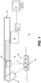
- FIG. 1 is a schematic diagram showing an imaging apparatus 70 for projecting and imaging using structured light patterns 46.
- Imaging apparatus 70 uses a handheld camera 24 for image acquisition according to an embodiment of the present disclosure.
- a control logic processor 80 or other type of computer that may be part of camera 24 controls the operation of an illumination array 10 that generates the structured light and controls operation of an imaging sensor array 30.
- Image data from surface 20, such as from a tooth 22, is obtained from imaging sensor array 30 and stored in a memory 72.
- Control logic processor 80 in signal communication with camera 24 components that acquire the image, processes the received image data and stores the mapping in memory 72.
- the resulting image from memory 72 is then optionally rendered and displayed on a display 74.
- Memory 72 may also include a display buffer for temporarily storing display 74 image content.
- a pattern of lines is projected from illumination array 10 toward the surface of an object from a given angle.
- the projected pattern from the surface is then viewed from another angle as a contour image, taking advantage of triangulation in order to analyze surface information based on the appearance of contour lines.
- Phase shifting in which the projected pattern is incrementally shifted spatially for obtaining additional measurements at the new locations, is typically applied as part of fringe projection imaging, used in order to complete the contour mapping of the surface and to increase overall resolution in the contour image.
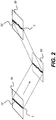
- the schematic diagram of Figure 2 shows, with the example of a single line of light L, how patterned light is used for obtaining surface contour information using a handheld camera or other portable imaging device.
- a mapping is obtained as an illumination array 10 directs a pattern of light onto a surface 20 and a corresponding image of a line L' is formed on an imaging sensor array 30.
- Each pixel 32 on imaging sensor array 30 maps to a corresponding pixel 12 on illumination array 10 according to modulation by surface 20. Shifts in pixel position, as represented in Figure 2 , yield useful information about the contour of surface 20.
- the basic pattern shown in Figure 2 can be implemented in a number of ways, using a variety of illumination sources and sequences and using one or more different types of sensor arrays 30.
- Illumination array 10 can utilize any of a number of types of arrays used for light modulation, such as a liquid crystal array or digital micromirror array, such as that provided using the Digital Light Processor or DLP device from Texas Instruments, Dallas, TX. This type of spatial light modulator is used in the illumination path to change the light pattern as needed for the mapping sequence.
- a liquid crystal array or digital micromirror array such as that provided using the Digital Light Processor or DLP device from Texas Instruments, Dallas, TX. This type of spatial light modulator is used in the illumination path to change the light pattern as needed for the mapping sequence.
- the image of the contour line on the camera simultaneously locates a number of surface points of the imaged object. This can speed the process of gathering many sample points, while the plane of light (and usually also the receiving camera) is laterally moved in order to "paint" some or all of the exterior surface of the object with the plane of light.
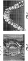
- Figure 3 shows surface imaging using a pattern with multiple lines of light. Incremental shifting of the line pattern and other techniques help to compensate for inaccuracies and confusion that can result from abrupt transitions along the surface, whereby it can be difficult to positively identify the segments that correspond to each projected line. In Figure 3 , for example, it can be difficult to determine whether line segment 16 is from the same line of illumination as line segment 18 or adjacent line segment 19.
- Figure 4 shows a dense point cloud 50 generated from a structured light imaging apparatus, CS 3500 3-D camera made by Carestream Health, Inc., Rochester NY, USA, using results from patterned illumination such as that shown in Figure 3 .
- the point cloud 50 models physical location of sampled points on tooth surfaces and other intraoral surfaces or, more generally, of surfaces of a real-world object. Variable resolution can be obtained.
- the example of Fig. 4 shows an exemplary 100 micron resolution.
- the points in the point cloud represent actual, measured points on the three dimensional surface of an object.
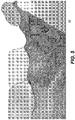
- the surface structure can be approximated from the point cloud representation by forming a polygon mesh, in which adjacent vertices are connected by line segments. For a vertex, its adjacent vertices are those vertices closest to the vertex in terms of Euclidean distance.
- Figure 5 shows a 3-D polygon mesh model 60 in the simple form of a triangular mesh.
- a triangular mesh forms a basic mesh structure that can be generated from a point cloud and used as a digital model to represent a 3-D object by its approximate surface shape, in the form of triangular plane segments sharing adjacent boundaries.
- Methods/apparatus for forming a polygon mesh model such as a triangular mesh or more complex mesh structure, are well known to those skilled in the contour imaging arts.
- the polygon unit of the mesh model, and relationships between neighboring polygons, can be used in embodiments of the present disclosure to extract features (e.g., curvatures, minimum curvatures, edges, spatial relations, etc.) at the teeth boundaries.
- segmentation of individual components of the image content from a digital model can be of value to the dental practitioner in various procedures, including orthodontic treatment and preparation of crowns, implants, and other prosthetic devices, for example.
- Various methods have been proposed and demonstrated for mesh-based segmentation of teeth from gums and of teeth from each other.
- drawbacks of conventional segmentation solutions include requirements for a significant level of operator skill and a high degree of computational complexity.
- Conventional approaches to the problem of segmenting tooth components and other dentition features have yielded disappointing results in many cases.
- Exemplary method and/or apparatus embodiments address such problems with segmentation that can utilize the polygonal mesh data as a type of source digital model and can operate in more than one stage: e.g., first, performing an automated segmentation algorithm/procedures that can provide at least a close or coarse approximation of the needed segmentation of the digital model; and second, allowing operator interactions to improve, correct and/or clean up observed errors and inconsistencies in the automated results, which can yield highly accurate results that are difficult to achieve in a purely automated manner, but not placing significant requirements on operator time or skill level and/or on needed computer resources.
- This hybrid approach in exemplary method and/or apparatus embodiments can help to combine computing and image processing power with operator perception to check, correct, and refine results of automated processing.
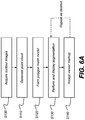
- the logic flow diagram of Figure 6A shows a hybrid sequence for tooth mesh segmentation and generation of a digital model to identify individual features or intraoral components such as teeth from within the mouth according to an exemplary embodiment of the present disclosure.
- an image acquisition step S100 a plurality of structured light images of the patient's dentition are captured, providing a set of contour images for processing.
- a point cloud generation step S110 then generates a point cloud of the patient's dentition using the set of contour images.
- a polygon mesh generation step S120 forms a polygon mesh by connecting adjacent points from the point cloud results.
- a triangular mesh provides one type of polygon mesh that can be readily generated for approximating a surface contour; more complex polygon mesh configurations can alternately be used.
- a segmentation step S130 can be executed.
- segmentation step S130 can distinguish teeth from gum tissue, as well as distinguishing one tooth from another. Segmentation results can then be displayed, showing the results of this initial, automated segmentation processing.
- the automated segmentation step S130 can provide an intermediate image.
- segmentation step S130 can perform the bulk of segmentation processing, but can further benefit from operator review and refinements of results.
- segmentation step S130 can use any of a number of known segmentation techniques, such as fast-marching watershed algorithms, so-called snake-based segmentation, and other methods known to those skilled in the imaging arts, as noted earlier.
- Figure 6A also shows an optional repeat loop that can enable viewer interaction with the intermediate image for refining the results of the automated segmentation processing, for example, using the basic apparatus shown in Figure 1 .
- An accept operator instructions step S140 can be executed, during which the viewer indicates, on the displayed results, seed points, seed lines, block lines, boundary features, or other markings that identify one or more distinct features of the segmentation results to allow further segmentation refinement and processing.
- Viewer markup instructions cause segmentation step S130 to be executed at least a second time, this second time using input markup(s) from entered viewer instructions. It can be appreciated that different segmentation algorithms can be applied at various stages of automated or manual processing. Final results of segmentation processing can be displayed, stored, and transmitted between computers, such as over a wired or wireless network, for example.
- tooth and gum partitioning can be automated.
- tooth and gum partitioning can use an automated curvature-based method that computes curvature of vertices in the mesh, and then uses a thresholding algorithm to identify margin vertices having large negative curvature.
- color-based segmentation can be used for tooth segmentation from the gums. This type of method can obtain average hue values from regions of the image and calculate threshold values that partition image content.
- FIG. 6B An exemplary embodiment of workflow for the hybrid tooth segmentation system is depicted in the logic flow diagram of Figure 6B .
- the control logic processor 80 ( Figure 1 ) initiates an automated segmentation step S202 in which a fully automatic tooth segmentation tool is evoked to delineate teeth and gum regions and delineate individual teeth regions.
- the fully automatic tooth segmentation tool employs exemplary algorithms such as active contour models published in the literature or otherwise well-known to those skilled in the image processing arts.
- the delineation of teeth effectively produces individually segmented teeth; however, these generated teeth may contain poorly segmented intraoral components.
- a first checking step S204 then checks for poorly segmented intraoral components.
- Checking for incorrect or incomplete segmentation in step S204 can be accomplished either computationally, such as by applying trained artificial intelligence algorithms to the segmentation results, or by viewer interaction, such as following visual inspection by the viewer.
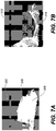
- Figure 7A shows an exemplary poorly segmented or mis-segmented tooth 302. As shown in Figure 7A , a segmented tooth boundary 306 is not aligned with an actual tooth boundary 308.
- a primary assisted segmentation step S206 executes, activating a segmentation procedure that is also automated, but allows some level of operator adjustment.
- Primary assisted segmentation step S206 applies an algorithm for segmentation that allows operator adjustment of one or more parameters in a parameter adjustment step S210.
- Another checking step S208 executes to determine if additional segmentation processing is needed.
- the adjustable parameter can be altered computationally or explicitly by an operator instruction in step S210. Subsequent figures show an exemplary operator interface for parameter adjustment.
- An exemplary algorithm employed in primary assisted segmentation Step S206 can be a well-known technique, such as the mesh minimum curvature-based segmentation method.
- the adjustable parameter can be the threshold value of the curvature.
- the delineation of teeth performed in Step S206 may still produce poorly segmented intraoral components or features, so that a repeated segmentation process is helpful.
- the checking of poor segmentation in step S208 can be accomplished either computationally, such as by applying artificial intelligence algorithms to the segmentation results, or more directly, by visual inspection performed by the user.
- the hybrid tooth segmentation system optionally allows the user to add exemplary geometric primitives such as seed lines on the tooth region and add blocking lines between the teeth or between the teeth and gum to aid the tooth segmentation process.
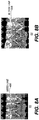
- Figure 8A shows an exemplary seed line 406 for marking a tooth, added to a mesh image 62.
- Figure 8B shows an exemplary block line 408 for indicating space between two teeth, added to a mesh image 62.
- Step S206, Step S208 and Step S210 in the Figure 6B sequence constitute an exemplary primary segmentation loop 54 that follows the fully automatic segmentation of step S202 and checking step S204.
- This exemplary primary segmentation loop 54 is intended to correct segmentation errors from the fully automated segmentation of automated segmentation step S202, as identified in step S204.
- Exemplary primary segmentation loop 54 can be executed one or more times, as needed. When exemplary primary segmentation loop 54 is successful, segmentation can be complete.
- an exemplary secondary segmentation loop 56 can be used to provide more interactive segmentation approaches.
- the secondary segmentation loop 56 can include an interactive segmentation step S212, another checking step S214, and an operator markup step S216.
- Interactive segmentation step S212 can activate a segmentation process that works with the operator for indicating areas of the image to be segmented from other areas.
- Interactive segmentation step S212 can have an automated sequence, implemented by an exemplary algorithm such as a "fast march" method known to those skilled in the image segmentation arts.
- Step S212 may require population of the tooth region images by operator-entered seeds or seed lines or other types of geometric primitives before activation or during processing.
- seed lines or other features can be automatically generated in Step S100, S110 and S120 when the dentition mesh is entered into the system for optional operator adjustment (e.g., subsequent operations such as secondary segmentation loop 56 or Step 212).
- the features, seeds or seed lines can be added to the segmentation process in operator markup Step S216 by the user.
- the results from Step S212 are subject to inspection by the user in Step S216. Results from the hybrid automated/interactive segmentation processing can then be displayed in a display step S220, as well as stored and transmitted to another computer.
- some exemplary methods/apparatus of the present disclosure provide a hybrid tooth segmentation that provides the benefits of interactive segmentation with human-machine synergy.
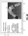
- FIGS 9A-9C show operator interface screens 52 for portions of a sequence for review and entry of markup instructions for refining mesh segmentation processing according to certain exemplary embodiments of the present disclosure.
- Interim mesh segmentation results are shown in a display area 86 on screen 52.
- a number of controls 90 for adjustment of the segmentation process are available, such as an adjustment control 84 for setting a level for overall aggressiveness or other parameter or characteristic of the segmentation processing algorithm.
- Optional selection controls 88 allow the viewer to specify one or more segmentation algorithms to be applied. This gives the operator an opportunity to assess whether one particular type of segmentation algorithm or another appear to be more successful in performing the segmentation task for the given mesh digital model. The operator can compare results against the original and adjust parameters to view results of successive segmentation attempts, with and without operator markup.
- Figure 9A also shows a trace pattern 96 that is entered as an operator seed line instruction for correcting or refining segmentation processing, as was shown previously with respect to Figure 8A .
- an operator mark in the form of trace pattern 96 or other arbitrary marking/geometric can be used to provide seed points that indicate a specific feature for segmentation, such as a molar or other tooth feature that may be difficult to process for conventional segmentation routines. Seed marks can then be used as input to a fast marching algorithm or other algorithm type, as described previously. In some cases, for example, adjacent teeth may not be accurately segmented with respect to each other; operator markup can provide useful guidance for segmentation processing where standard segmentation logic does not perform well.
- the operator can have controls 90 available that allow the entered markup to be cleared or provided to the segmentation processor.
- controls 90 color or shading can be used to differentiate various teeth or other structures identified by segmentation. Additional controls 90 can also be used to display individual segmented elements, such as individual teeth, for example.
- individual controls 90 can be used individually or in combination.
- segmentation of individual teeth from each other can use curvature thresholds to compute margin and border vertices, then use various growth techniques to define the bounds of each tooth relative to margin detection.
- controls 90 can include, but are not limited to enter/adjust seed or boundary geometries, enter/adjust selected segmentation procedures, enter/adjust number of objects to segment, subdivide selected object, modify segmented object display, etc.
- the segmentation that is provided using structured light illumination and detection can be correlated with 3D image results obtained from CBCT or other radiographic method for volume image reconstruction.
- Certain exemplary method and/or apparatus embodiments of the present disclosure can provide iterative segmentations that allow the practitioner to utilize different segmentation methods/algorithms in an efficient manner.
- different segmentation methods are available; each method has its strengths and shortcomings for effective characterization of the visible tooth structure.
- a logic flow diagram of Figure 10 shows exemplary imaging method embodiments that allow the practitioner to take advantage of successive segmentation techniques in constructing a set of well-segmented teeth, so that a full dental arch can be efficiently characterized.
- the practitioner can record individual teeth that are properly segmented and eliminate them from further segmentation processing that could otherwise compromise successful results and complicate the segmentation task.
- individual teeth that are properly segmented e.g., segmentation factor or segmentation characteristic (e.g., determined by the processor) is sufficient
- segmentation factor or segmentation characteristic e.g., determined by the processor
- the task of the segmentation process is to construct, in an iterative and interactive manner, a recorded set 100 of well-segmented teeth from a 3-D digital mesh model of the patient's dentition.
- This can include the full dental arch, as shown in the example that follows; alternately, the full recorded set 100 can include only a partial portion of the dental arch that is of interest for a particular patient.
- the logic flow iteratively identifies and "records" well-segmented teeth and thus “removes" them from the "3-D digital mesh model" that is actively being processed. In this way, subsequent segmentation processing works with a reduced set of un-segmented structures, correspondingly reducing the number of calculations and/or overall complexity of the segmentation problem as processing continues.
- the segmentation procedure shown in Figure 10 starts with an initialization step S1010 that begins with the obtained 3-D mesh model and a recorded set 100 that is, initially, an empty set ⁇ ⁇ for listing properly segmented teeth and for removing these properly segmented teeth from further segmentation processing.
- a segmentation step S1020 the practitioner selects a first segmentation algorithm for initial segmentation of the 3-D mesh, after the execution of the scan sequence using intraoral camera 24 ( Figure 1 ).
- the first segmentation is the automatic segmentation as illustrated by step S202 in Figure 6B .
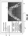
- the segmentation results from step S 1020 in Figure 10 can display to the practitioner as shown in the example screen of Figure 11 .
- Segmented areas of the teeth can appear in color or grayscale values that highlight the segmented tooth areas within the mesh.
- a number of teeth in the arch are well-segmented in this example; these well-segmented teeth can be recorded and removed from the 3-D mesh model that requires further processing. Other teeth may not be well-segmented, such as those shown having perceptible gaps and other errors.
- the practitioner uses a touch screen, mouse, or other pointer or keyboard entry to highlight or otherwise indicate well-segmented teeth.
- the practitioner then enters a Set instruction 110 or other operator instruction that adds the well-segmented teeth to the recorded set 100, as described previously.
- This can include commands to set and unset a particular segmentation, for example.
- the Set instruction 110 records each of the specified segmented teeth in set 100 and effectively removes the recorded teeth from the 3-D mesh model, thereby forming a modified 3-D mesh model. Teeth in the recorded set 100 are considered to be well-segmented and are thus removed from further segmentation processing.
- Subsequent iterative processing can then focus on the smaller group of teeth that remain in the 3-D mesh model and that have not been successfully segmented by the initial segmentation algorithm. Iteratively reducing the size of the poorly-segmented data within the 3-D mesh model helps to reduce processing time and complexity and allows adjustment or change of the segmentation method and use of more specialized or more interactive segmentation techniques to be used on the smaller subset of teeth that still require processing.
- a modified segmentation procedure is identified or defined for use in processing what remains in the modified 3-D mesh model. As described in more detail subsequently, the segmentation procedure can make use of a different algorithm or may use a similar algorithm with adjusted parameters, such as changed threshold values for example.
- An interactive process can be used for identifying well-segmented teeth that can be added to recorded set 100 in recording step S 1030.
- the practitioner upon examining segmentation results tooth-by-tooth, selects and highlights the teeth that show acceptable segmentation, such as using a touch screen or other pointer. The practitioner then enters a Set instruction 110 that records each successfully segmented tooth, thus adding the tooth to the recorded set 100 as shown with reference to Figure 10 , removing the tooth from the active 3-D mesh being processed.
- the practitioner may respond to system prompts to enter seed points or other markings, as described with reference to step S216 in Figure 6B , to assist in more successful segmentation.
- a test step S1040 provides the practitioner with a number of options for the remaining teeth, depending on the success or failure of the segmentation strategy that has been applied.
- One option is to execute a parameter adjustment step S1050 to obtain the modified segmentation procedure, then to retry segmentation on the teeth not yet recorded using adjusted parameter settings with the exemplary primary assisted segmentation algorithm indicated in Step S206.
- the practitioner can set an adjustment level to a different value for a more or less "aggressive" segmentation processing or can adjust thresholds that determine classification of features.
- Another option is an alternate execution step S1060. For step S1060, the practitioner selects a different segmentation technique for teeth not yet suitably segmented.
- a display step S1070 executes at the end of segmentation processing, allowing the practitioner to view a displayed image and to store or transmit processing results as needed.
- one or more teeth that have been segmented can be "cleared” and restored or returned to the 3-D mesh model using a Clear instruction 112 ( Figure 11 ).
- a Clear instruction 112 Figure 11
- the viewer may determine that results for a particular tooth are not satisfactory or can be improved and that additional segmentation procedures would be helpful.
- Restoring a specified tooth to the modified 3-D mesh model allows further processing of the tooth in subsequent segmentation operations, either using different segmentation algorithms or applying different values to segmentation variables.
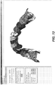
- Figure 12 shows a set of well-segmented teeth from the example segmentation of Figure 11 (e.g., that are removed from further segmentation iterations/processing).
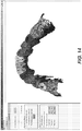
- Figure 13 shows segmentation results following parameter adjustment and subsequent segmentation of the four poorly segmented teeth of Figure 11 , as described previously with reference to step S1050, which are now more accurately segmented.
- the margin lines are more accurate.
- Figure 14 shows complete segmentation results for the full dental arch, obtained using the process described with reference to Figure 10 .
- Figure 14 shows the well segmented recorded teeth from a first segmentation (e.g., Figure 11 ) with well segmented recorded teeth from a second segmentation (e.g., Figure 13 ).
- sufficiently segmented teeth can be automatically removed from additional segmentations that are run before mesh segmentation results (e.g., interim mesh segmentation results shown in the display area 86 or final segmentation results) are displayed to the user.
- individual teeth that are properly segmented after a first segmentation is performed on a 3D mesh can be automatically removed or eliminated from further/subsequent segmentation(s) or a second segmentation applied to remaining portions of the 3D mesh (e.g., teeth).
- a confidence factor threshold can be used to remove segmented teeth (e.g., portions) from the 3D mesh. Such a confidence factor threshold can be preset, variable and/or set by the user.
- Exemplary confidence factors can be computed based on one or more technical metrics such as but not limited to the probability distribution function (PDF) of a segmented tooth surface normals and/or exemplary morphological descriptor of the boundaries of a segmented tooth.
- PDF probability distribution function
- the PDF of surface normals can be practically computed as the normal histogram as an exemplary technology.
- the morphological descriptor of the boundaries can be computed using an exemplary computer vision technology named chain coding.
- Other technical metrics known in the dental image processing art can be used.
- Alternative confidence factors can be weighted combination of such technical metrics and/or scaled to a prescribed range such as a range between 0 to 1.
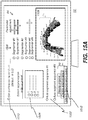
- Figures 15A-15B are diagrams that shows an exemplary user interface with controls to preset and/or change an order for sequential segmentations successively used in an automatic segmentation process.
- Each successive segmentation in certain exemplary automatic segmentation embodiments can record and then remove teeth segmented with a confidence factor over a threshold from further segmentation.
- the complete segmentation results for the full dental arch (or portion thereof) can be displayed when all individual teeth are recorded.
- the complete segmentation results for the full dental arch (or portion thereof) can be displayed when all segmentations have been run and any teeth that were not recorded (and removed) can be indicated for the practitioner.
- a preset sequence 1502 of segmentation types can be selected or the practitioner can set a desired order 1504 of segmentation types selected from a library or plurality of segmentation types 1506.
- the adjustment control 84 can be used to set a level for overall aggressiveness or other parameter(s) or characteristic(s) of a specific segmentation processing algorithm type among segmentation types 1506.
- the confidence factor 1510 can be optional and capable of adjustment by the practitioner.
- operator controls 90 can be used to display to the practitioner the complete segmentation results.
- An optional window 1508 can be used to display the original 3D mesh or the segmented result or the segmented result with segmentation types actually used.
- operator control 1512 can be used to display to the practitioner the complete segmentation results for the full dental arch (or portion thereof) when all segmentations have been run with the segmentation type 1514 highlighted for each recorded tooth as shown in Figure 15B .
- a computer program can use stored instructions that perform on image data that is accessed from an electronic memory.
- a computer program for operating the imaging system and probe and acquiring image data in exemplary embodiments of the application can be utilized by a suitable, general-purpose computer system operating as control logic processors as described herein, such as a personal computer or workstation.
- control logic processors as described herein
- many other types of computer systems can be used to execute the computer program of the present invention, including an arrangement of networked processors, for example.
- the computer program for performing exemplary method embodiments may be stored in a computer readable storage medium.
- This medium may include, for example; magnetic storage media such as a magnetic disk such as a hard drive or removable device or magnetic tape; optical storage media such as an optical disc, optical tape, or machine readable optical encoding; solid state electronic storage devices such as random access memory (RAM), or read only memory (ROM); or any other physical device or medium employed to store a computer program.
- Computer programs for performing exemplary method embodiments may also be stored on computer readable storage medium that is connected to the image processor by way of the internet or other network or communication medium. Those skilled in the art will further readily recognize that the equivalent of such a computer program product may also be constructed in hardware.
- memory can refer to any type of temporary or more enduring data storage workspace used for storing and operating upon image data and accessible to a computer system, including a database, for example.
- the memory could be non-volatile, using, for example, a long-term storage medium such as magnetic or optical storage. Alternately, the memory could be of a more volatile nature, using an electronic circuit, such as random-access memory (RAM) that is used as a temporary buffer or workspace by a microprocessor or other control logic processor device.
- Display data for example, is typically stored in a temporary storage buffer that is directly associated with a display device and is periodically refreshed as needed in order to provide displayed data.
- This temporary storage buffer is also considered to be a type of memory, as the term is used in the application.
- Memory is also used as the data workspace for executing and storing intermediate and final results of calculations and other processing.
- Computer-accessible memory can be volatile, non-volatile, or a hybrid combination of volatile and non-volatile types.
- computer program products of the application may make use of various image manipulation algorithms and processes that are well known.
- computer program product exemplary embodiments of the application may embody algorithms and processes not specifically shown or described herein that are useful for implementation. Such algorithms and processes may include conventional utilities that are within the ordinary skill of the image processing arts. Additional aspects of such algorithms and systems, and hardware and/or software for producing and otherwise processing the images or co-operating with the computer program product exemplary embodiments of the application, are not specifically shown or described herein and may be selected from such algorithms, systems, hardware, components and elements known in the art.
- Certain exemplary method and/or apparatus embodiments according to the application can allow the practitioner to take advantage of successive segmentation techniques to remove properly segmented dentition from subsequent different segmentation attempts in constructing a set of well-segmented teeth from a dentition 3D mesh model.
- operator controls can be used to display to the practitioner segmentation types that recorded each tooth in the complete automatic segmentation results.
- embodiments of the present disclosure are illustrated using dental imaging apparatus, similar principles can be applied for other types of diagnostic imaging and for other anatomy.
- Exemplary embodiments according to the application can include various features described herein (individually or in combination).
- an apparatus for intraoral imaging xan include a structured light imaging camera that is configured to acquire a 3-D mesh model of a patient's dentition, and a computer processor in signal communication with the imaging camera and with a display and that is programmed with instructions for: executing a first segmentation procedure on the obtained 3-D mesh model and displaying one or more segmented teeth from the 3-D mesh model, recording at least one of the one or more segmented teeth according to operator instruction and removing the recorded at least one tooth from the 3-D mesh model to form a modified 3-D mesh model, repeating, one or more times, a sequence of: (i) identifying a modified segmentation procedure, (ii) executing the modified segmentation procedure on the modified 3-D mesh model and displaying one or more segmented teeth from the modified 3-D mesh model, and (iii) recording at least one of the one or more segmented teeth and removing the recorded at least one tooth from the modified 3-D mesh model, and displaying, storing, or transmitting recorded segmentation results.
Description
- The disclosure relates generally to segmentation of elements that are represented by a three-dimensional mesh and more particularly to methods and apparatus for automated tooth segmentation in a contour image.
- Three-dimensional (3-D) imaging and 3-D image processing are areas of growing interest to dental/orthodontic practitioners for computer-aided diagnosis and overall improved patient care. In the field of cephalometric analysis, 3-D imaging and 3-D image processing offer significant advantages in terms of flexibility, accuracy, and repeatability. 3-D cephalometric analysis overcomes some of the shortcomings associated with conventional methods of two-dimensional (2-D) cephalometric analysis, such as 2-D geometric errors of perspective projection, magnification, and head positioning in projection, for example. 3-D cephalometrics has been shown to yield objective data that is more accurate, since it is based on calculation rather than being largely dependent upon discrete measurements, as is the case with 2-D cephalometrics.
- Early research using 3-D cephalometrics methods employed 3-D imaging and parametric analysis of maxillo-facial anatomical structures using cone beam computed tomography (CBCT) of a patient's head. Using CBCT methods, a significant role of the 3-D cephalometric analysis was to define mathematical models of maxillary and mandibular arches for which the axes of inertia were calculated for each tooth or group of teeth. This, in turn, required the segmentation of individual teeth from the acquired CBCT head volume of a patient.
- Conventionally, during an orthodontic treatment procedure, multiple 2-D X-ray cephalogram acquisitions are used to assess treatment progress. Conventional 3-D cephalometric analysis can also be used for this purpose, requiring multiple CBCT scans. However, both 2-D and 3-D radiographic imaging methods expose the patient to ionizing radiation. Reducing overall patient exposure to radiation is desirable, particularly for younger patients.
- Optical intraoral scans, in general, produce contours of dentition objects and have been helpful in improving visualization of teeth, gums, and other intra-oral structures. Surface contour information can be particularly useful for assessment of tooth condition and has recognized value for various types of dental procedures, such as for restorative dentistry. This can provide a valuable tool to assist the dental practitioner in identifying various problems and in validating other measurements and observations related to the patient's teeth and supporting structures. Surface contour information can also be used to generate 3-D models of dentition components such as individual teeth; the position and orientation information related to individual teeth can then be used in assessing orthodontic treatment progress. With proper use of surface contour imaging, the need for multiple 2-D or 3-D X-ray acquisitions of a patient's dentition can be avoided.
- A number of techniques have been developed for obtaining surface contour information from various types of objects in medical, industrial, and other applications. Optical 3-dimensional (3-D) measurement methods provide shape and spatial information using light directed onto a surface in various ways. Among types of imaging methods used for contour imaging are fringe projection devices. Fringe projection imaging uses patterned or structured light and camera/sensor triangulation to obtain surface contour information for structures of various types. Once the fringe projection images are processed, a point cloud can be generated. A mesh can then be formed from the point cloud or a plurality of point clouds, in order to reconstruct at least a planar approximation to the surface.
- Mesh representation can be particularly useful for showing surface structure of teeth and gums and can be obtained using a handheld camera and without requiring harmful radiation levels. However, when using conventional image processing approaches, mesh representation has been found to lack some of the inherent versatility and utility that is available using cone-beam computed tomography (CBCT) or other techniques that expose the patient to radiation. One area in which mesh representation has yielded only disappointing results relates to segmentation. Segmentation allows the practitioner to identify and isolate the crown and other visible portions of the tooth from gums and related supporting structure. Conventional methods for segmentation of mesh images can often be inaccurate and may fail to distinguish tooth structure from supporting tissues.
- Various approaches for addressing the segmentation problem for mesh images have been proposed, such as the following:
- (i) A method described in the article "Snake-Based Segmentation of Teeth from Virtual Dental Casts" by Thomas Kronfeld et al. (in Computer-Aided Design & applications, 7(a), 2010) employs an active contour segmentation method that attempts to separate every tooth and gum surface in a single processing iteration. The approach that is described, however, is not a topology-independent method and can fail, particularly where there are missing teeth in the jaw mesh.
- (ii) An article entitled "Perception-based 3D Triangle Mesh Segmentation Using Fast Marching Watershed" by Page, D.L. et al. (in Proc. CVPI vol II 2003) describes using a Fast Marching Watershed method for mesh segmentation. The Fast Marching Watershed method that is described requires the user to manually enter seed points. The seed points must be placed at both sides of the contours of the regions under segmentation. The method then attempts to segment all regions in one step, using seed information. For jaw mesh segmentation, this type of method segments each tooth as well as the gum at the same time. This makes the method less desirable, because segmenting teeth from the gum region typically requires parameters and processing that differ from those needed for the task of segmenting teeth from each other. Using different segmentation strategies for different types of dentition components with alternate segmentation requirements would provide better performance.
- (iii) For support of his thesis, "Evaluation of software developed for automated segmentation of digital dental models", J.M. Moon used a software tool that decomposed the segmentation process into two steps: separation of teeth from gingival structure and segmentation of whole arch structure into individual tooth objects. The software tool used in Moon's thesis finds maximum curvature in the mesh and requires the user to manually choose a curvature threshold to obtain margin vertices that are used for segmenting the tooth. The software also requires the user to manually edit margins in order to remove erroneous segmentation results. Directed to analysis of shape and positional characteristics, this software tool does not consider employing color information in the separation of teeth regions from the gum regions.
- (iv)
US 2003 0 039 389 A1 entitled "Manipulation a digital dentition model to form models of individual dentition components" by Jones, T. N. et al. disclose a method of separating portions of the dentition model representing the adjacent teeth. - (v)
WO 01 74268 A1 - (vi)
US 2016 004 811 A1 discloses a method for detecting tooth wear using digital 3D models of teeth taken at different times. These models are segmented to identify individual teeth within the digital 3D model. The segmentation includes performing a first and a second segmentation method, wherein the results are combined to generate segmented digital 3D models which are then compared to detect tooth wear by determining differences between the segmented models, where the differences relate to the same tooth to detect wear on the tooth over time. - (vii)
CN 102 147 935 A discloses a method suitable for segmenting a dental triangle mesh curved surface from a dental jaw triangle mesh curved surface. - Each of these segmentation approach has its strengths and weaknesses for automating the segmentation process. Some teeth are readily identified and can be segmented with high accuracy using snake-based segmentation, for example. However, this same segmentation routine may perform poorly for teeth of different shapes or positioned differently within the same dental arch.
- Because different segmentation routines work well but vary in performance based on tooth shape, size, position, and other characteristics, no one segmentation approach can be optimized for all teeth or for all situations. Thus, it can be seen that there would be advantages to a flexible approach for applying tooth segmentation. There is, then, a need for improved methods for segmentation of mesh representation of dentition.
- In accordance with the present invention, a computer-implemented method for generating one or more segmented 3-D teeth models and an apparatus for intraoral imaging as set forth in
Claims 1 and 14, respectively, are provided. Further embodiments of the invention are inter alia disclosed in the dependent claims. An aspect of this application is to advance the art of tooth segmentation in relation to volume imaging and visualization used in medical and dental applications. - Another aspect of this application is to address, in whole or in part, at least the foregoing and other deficiencies in the related art.
- It is another aspect of this application to provide, in whole or in part, at least the advantages described herein.
- Method and/or apparatus embodiments according to the present disclosure can allow the viewer to have the advantages of automated segmentation as well as the capability to interact with partially automated or manual segmentation processing in order to help provide progressively improved results.
- These objects are given only by way of illustrative example, and such objects may be exemplary of one or more embodiments of the invention. Other desirable objectives and advantages inherently achieved in the present disclosure may occur or become apparent to those skilled in the art. The invention is defined by the appended claims.
- According to one aspect of the disclosure, there is provided a computer-implemented method for generating one or more segmented 3-D teeth models, that can include obtaining a 3-D mesh model of a patient's dentition, executing a first segmentation procedure on the obtained 3-D mesh model and displaying one or more segmented teeth from the 3-D mesh model, recording at least one of the one or more segmented teeth according to operator instruction and removing the recorded at least one tooth from the 3-D mesh model to form a modified 3-D mesh model, repeating, one or more times, a sequence of (i) identifying a modified segmentation procedure; (ii) executing the modified segmentation procedure on the modified 3-D mesh model and displaying one or more segmented teeth from the modified 3-D mesh model; (iii) recording at least one of the one or more segmented teeth and removing the recorded at least one tooth from the modified 3-D mesh model, and displaying, storing, or transmitting recorded segmentation results.
- The foregoing and other objects, features, and advantages of the invention will be apparent from the following more particular description of the embodiments of the invention, as illustrated in the accompanying drawings. The elements of the drawings are not necessarily to scale relative to each other.
-
Figure 1 is a schematic diagram that shows components of an imaging apparatus for surface contour imaging of a patient's teeth and related structures. -
Figure 2 shows schematically how patterned light is used for obtaining surface contour information using a handheld camera or other portable imaging device. -
Figure 3 shows an example of surface imaging using a pattern with multiple lines of light. -
Figure 4 shows a point cloud generated from structured light imaging, such as that shown inFigure 3 . -
Figure 5 shows apolygon mesh 60 in the simple form of a triangular mesh. -
Figure 6A is a logic flow diagram that shows a hybrid sequence for mesh segmentation according to an embodiment of the present disclosure. -
Figure 6B is a logic flow diagram that shows a workflow sequence for hybrid segmentation of the tooth according to an embodiment of the present disclosure. -
Figure 7A shows an example of a poorly segmented tooth. -
Figure 7B shows an example of an improved segmentation. -
Figure 8A shows an example of a seed line trace pattern. -
Figure 8B shows an example of a block line trace pattern. -
Figures 9A ,9B and9C show operator interface screens for review and entry of markup instructions for refining tooth mesh segmentation processing according to certain embodiments of the present disclosure. -
Figure 10 is a logic flow diagram that shows steps in iterative execution of segmentation. -
Figure 11 shows a display showing a possible segmentation of portions of the dental arch. -
Figure 12 shows a set of well-segmented teeth from the example segmentation ofFigure 11 . -
Figure 13 shows segmentation results following parameter adjustment by the viewing practitioner. -
Figure 14 shows complete segmentation results for the full dental arch, obtained using the process described herein. -
Figures 15A-15B are diagrams that shows an exemplary user interface with controls to preset and/or change an order for sequential segmentations successively used in automatic segmentation methods/apparatus according to certain embodiments of the present disclosure. - The following is a detailed description of exemplary embodiments, reference being made to the drawings in which the same reference numerals identify the same elements of structure in each of the several figures.
- Where they are used, the terms "first", "second", and so on, do not necessarily denote any ordinal or priority relation, but may be used for more clearly distinguishing one element or time interval from another.
- The term "exemplary" indicates that the description is used as an example, rather than implying that it is an ideal.
- The term "in signal communication" as used in the application means that two or more devices and/or components are capable of communicating with each other via signals that travel over some type of signal path. Signal communication may be wired or wireless. The signals may be communication, power, data, or energy signals which may communicate information, power, and/or energy from a first device and/or component to a second device and/or component along a signal path between the first device and/or component and second device and/or component. The signal paths may include physical, electrical, magnetic, electromagnetic, optical, wired, and/or wireless connections between the first device and/or component and second device and/or component. The signal paths may also include additional devices and/or components between the first device and/or component and second device and/or component.
- In the context of the present disclosure, the terms "pixel" and "voxel" may be used interchangeably to describe an individual digital image data element, that is, a single value representing a measured image signal intensity. Conventionally an individual digital image data element is referred to as a voxel for 3-dimensional or volume images and a pixel for 2-dimensional (2-D) images. For the purposes of the description herein, the terms voxel and pixel can generally be considered equivalent, describing an image elemental datum that is capable of having a range of numerical values. Voxels and pixels have attributes of both spatial location and image data code value.
- "Patterned light" is used to indicate light that has a predetermined spatial pattern, such that the light has one or more features such as one or more discernable parallel lines, curves, a grid or checkerboard pattern, or other features having areas of light separated by areas without illumination. In the context of the present disclosure, the phrases "patterned light" and "structured light" are considered to be equivalent, both used to identify the light that is projected toward a subject in order to derive contour image data.
- In the context of the present disclosure, the terms "viewer", "operator", and "user" are considered to be equivalent and refer to the viewing practitioner, technician, or other person who can view and manipulate a contour image that is formed from a combination of multiple structured light images on a display monitor. For segmentation processing, for example, the viewer is likely a dental practitioner.
- A "viewer instruction", "operator instruction", or "operator command" can be obtained from explicit commands entered by the viewer or may be implicitly obtained or derived based on some other user action, such as making an equipment setting, for example. With respect to entries entered on an operator interface, such as an interface using a display monitor and keyboard, for example, the terms "command" and "instruction" may be used interchangeably to refer to an operator entry.
- In the context of the present disclosure, a single projected line of light is considered a "one dimensional" pattern, since the line has an almost negligible width, such as when projected from a line laser, and has a length that is its predominant dimension. Two or more of such lines projected side by side, either simultaneously or in a scanned arrangement, provide a simple two-dimensional pattern. In exemplary embodiments, lines of light can be linear, curved or three-dimensional. This projected pattern can be used to characterize the surface features of a tooth or other anatomical structure.
- The terms "3-D model", "point cloud", "3-D surface", and "mesh" may be used synonymously in the context of the present disclosure. The dense point cloud is formed using techniques familiar to those skilled in the volume imaging arts for forming a point cloud and relates generally to methods that identify, from the point cloud, vertex points corresponding to surface features. The dense point cloud is thus generated using the reconstructed contour data from one or more reflectance images. Dense point cloud information serves as the basis for a polygon model or mesh at high density for the teeth and gum surfaces.
- According to the present disclosure, the phrase "geometric primitive" refers to basic 2-D geometric shapes that can be entered by the operator in order to indicate areas of an image. By way of example, and not limitation, geometric primitives can include lines, curves, points, and other open shapes, as well as closed shapes that can be formed by the operator, such as circles, closed curves, rectangles and squares, polygons, and the like.
- Embodiments of the present disclosure provide exemplary methods and/or apparatus that can help to eliminate the need for multiple CBCT scans for visualization of tooth and jaw structures. Exemplary methods and/or apparatus embodiments can be used to combine a single CBCT volume with optical intraoral scans that have the capability of tracking the root position at various stages of orthodontic treatment, for example. To achieve this, the intraoral scans are segmented so that exposed portions, such as individual tooth crowns, from the intraoral scan can be aligned with the individual tooth and root structure segmented from the CBCT volume.
-
Figure 1 is a schematic diagram showing animaging apparatus 70 for projecting and imaging using structuredlight patterns 46.Imaging apparatus 70 uses ahandheld camera 24 for image acquisition according to an embodiment of the present disclosure. Acontrol logic processor 80, or other type of computer that may be part ofcamera 24 controls the operation of anillumination array 10 that generates the structured light and controls operation of animaging sensor array 30. Image data fromsurface 20, such as from atooth 22, is obtained fromimaging sensor array 30 and stored in a memory 72.Control logic processor 80, in signal communication withcamera 24 components that acquire the image, processes the received image data and stores the mapping in memory 72. The resulting image from memory 72 is then optionally rendered and displayed on adisplay 74. Memory 72 may also include a display buffer for temporarily storingdisplay 74 image content. - In fringe projection imaging of a surface, a pattern of lines is projected from
illumination array 10 toward the surface of an object from a given angle. The projected pattern from the surface is then viewed from another angle as a contour image, taking advantage of triangulation in order to analyze surface information based on the appearance of contour lines. Phase shifting, in which the projected pattern is incrementally shifted spatially for obtaining additional measurements at the new locations, is typically applied as part of fringe projection imaging, used in order to complete the contour mapping of the surface and to increase overall resolution in the contour image. - The schematic diagram of
Figure 2 shows, with the example of a single line of light L, how patterned light is used for obtaining surface contour information using a handheld camera or other portable imaging device. A mapping is obtained as anillumination array 10 directs a pattern of light onto asurface 20 and a corresponding image of a line L' is formed on animaging sensor array 30. Eachpixel 32 onimaging sensor array 30 maps to a correspondingpixel 12 onillumination array 10 according to modulation bysurface 20. Shifts in pixel position, as represented inFigure 2 , yield useful information about the contour ofsurface 20. It can be appreciated that the basic pattern shown inFigure 2 can be implemented in a number of ways, using a variety of illumination sources and sequences and using one or more different types ofsensor arrays 30.Illumination array 10 can utilize any of a number of types of arrays used for light modulation, such as a liquid crystal array or digital micromirror array, such as that provided using the Digital Light Processor or DLP device from Texas Instruments, Dallas, TX. This type of spatial light modulator is used in the illumination path to change the light pattern as needed for the mapping sequence. - By projecting and capturing images that show structured light patterns that duplicate the arrangement shown in
Figures 1 and2 multiple times, the image of the contour line on the camera simultaneously locates a number of surface points of the imaged object. This can speed the process of gathering many sample points, while the plane of light (and usually also the receiving camera) is laterally moved in order to "paint" some or all of the exterior surface of the object with the plane of light. -
Figure 3 shows surface imaging using a pattern with multiple lines of light. Incremental shifting of the line pattern and other techniques help to compensate for inaccuracies and confusion that can result from abrupt transitions along the surface, whereby it can be difficult to positively identify the segments that correspond to each projected line. InFigure 3 , for example, it can be difficult to determine whetherline segment 16 is from the same line of illumination asline segment 18 oradjacent line segment 19. - By knowing the instantaneous position of the camera and the instantaneous position of the line of light within an object-relative coordinate system when the image was acquired, a computer and software can use triangulation methods to compute the coordinates of numerous illuminated surface points. As the plane is moved to intersect eventually with some or all of the surface of the object, the coordinates of an increasing number of points are accumulated. As a result of this image acquisition, a point cloud of vertex points or vertices can be identified and used to represent the extent of a surface within a volume. By way of example,
Figure 4 shows adense point cloud 50 generated from a structured light imaging apparatus, CS 3500 3-D camera made by Carestream Health, Inc., Rochester NY, USA, using results from patterned illumination such as that shown inFigure 3 . Thepoint cloud 50 models physical location of sampled points on tooth surfaces and other intraoral surfaces or, more generally, of surfaces of a real-world object. Variable resolution can be obtained. The example ofFig. 4 shows an exemplary 100 micron resolution. The points in the point cloud represent actual, measured points on the three dimensional surface of an object. - The surface structure can be approximated from the point cloud representation by forming a polygon mesh, in which adjacent vertices are connected by line segments. For a vertex, its adjacent vertices are those vertices closest to the vertex in terms of Euclidean distance.
- By way of example,
Figure 5 shows a 3-Dpolygon mesh model 60 in the simple form of a triangular mesh. A triangular mesh forms a basic mesh structure that can be generated from a point cloud and used as a digital model to represent a 3-D object by its approximate surface shape, in the form of triangular plane segments sharing adjacent boundaries. Methods/apparatus for forming a polygon mesh model, such as a triangular mesh or more complex mesh structure, are well known to those skilled in the contour imaging arts. The polygon unit of the mesh model, and relationships between neighboring polygons, can be used in embodiments of the present disclosure to extract features (e.g., curvatures, minimum curvatures, edges, spatial relations, etc.) at the teeth boundaries. - In intra-oral imaging, segmentation of individual components of the image content from a digital model can be of value to the dental practitioner in various procedures, including orthodontic treatment and preparation of crowns, implants, and other prosthetic devices, for example. Various methods have been proposed and demonstrated for mesh-based segmentation of teeth from gums and of teeth from each other. However, drawbacks of conventional segmentation solutions include requirements for a significant level of operator skill and a high degree of computational complexity. Conventional approaches to the problem of segmenting tooth components and other dentition features have yielded disappointing results in many cases. Exemplary method and/or apparatus embodiments according to the present disclosure address such problems with segmentation that can utilize the polygonal mesh data as a type of source digital model and can operate in more than one stage: e.g., first, performing an automated segmentation algorithm/procedures that can provide at least a close or coarse approximation of the needed segmentation of the digital model; and second, allowing operator interactions to improve, correct and/or clean up observed errors and inconsistencies in the automated results, which can yield highly accurate results that are difficult to achieve in a purely automated manner, but not placing significant requirements on operator time or skill level and/or on needed computer resources. This hybrid approach in exemplary method and/or apparatus embodiments can help to combine computing and image processing power with operator perception to check, correct, and refine results of automated processing.
- The logic flow diagram of
Figure 6A shows a hybrid sequence for tooth mesh segmentation and generation of a digital model to identify individual features or intraoral components such as teeth from within the mouth according to an exemplary embodiment of the present disclosure. In an image acquisition step S100, a plurality of structured light images of the patient's dentition are captured, providing a set of contour images for processing. A point cloud generation step S110 then generates a point cloud of the patient's dentition using the set of contour images. A polygon mesh generation step S120 forms a polygon mesh by connecting adjacent points from the point cloud results. A triangular mesh provides one type of polygon mesh that can be readily generated for approximating a surface contour; more complex polygon mesh configurations can alternately be used. - Continuing with the
Figure 6A sequence, given the polygon mesh, a segmentation step S130 can be executed. For a dental contour image, for example, segmentation step S130 can distinguish teeth from gum tissue, as well as distinguishing one tooth from another. Segmentation results can then be displayed, showing the results of this initial, automated segmentation processing. The automated segmentation step S130 can provide an intermediate image. Thus automated step S130 can perform the bulk of segmentation processing, but can further benefit from operator review and refinements of results. For its automatic processing, segmentation step S130 can use any of a number of known segmentation techniques, such as fast-marching watershed algorithms, so-called snake-based segmentation, and other methods known to those skilled in the imaging arts, as noted earlier. -
Figure 6A also shows an optional repeat loop that can enable viewer interaction with the intermediate image for refining the results of the automated segmentation processing, for example, using the basic apparatus shown inFigure 1 . An accept operator instructions step S140 can be executed, during which the viewer indicates, on the displayed results, seed points, seed lines, block lines, boundary features, or other markings that identify one or more distinct features of the segmentation results to allow further segmentation refinement and processing. Viewer markup instructions cause segmentation step S130 to be executed at least a second time, this second time using input markup(s) from entered viewer instructions. It can be appreciated that different segmentation algorithms can be applied at various stages of automated or manual processing. Final results of segmentation processing can be displayed, stored, and transmitted between computers, such as over a wired or wireless network, for example. - The process shown in
Figure 6A can thus allow automated segmentation to perform the coarse segmentation (e.g., first segmentation) that can be more easily accomplished, such as segmentation of teeth from gum tissue, for example. Thus, for example, tooth and gum partitioning can be automated. In one embodiment, tooth and gum partitioning can use an automated curvature-based method that computes curvature of vertices in the mesh, and then uses a thresholding algorithm to identify margin vertices having large negative curvature. Alternately, color-based segmentation can be used for tooth segmentation from the gums. This type of method can obtain average hue values from regions of the image and calculate threshold values that partition image content. - An exemplary embodiment of workflow for the hybrid tooth segmentation system is depicted in the logic flow diagram of
Figure 6B . Upon receiving a dentition mesh such as the one described in Step S 120 and shown inFigs. 4 and5 , the control logic processor 80 (Figure 1 ) initiates an automated segmentation step S202 in which a fully automatic tooth segmentation tool is evoked to delineate teeth and gum regions and delineate individual teeth regions. The fully automatic tooth segmentation tool employs exemplary algorithms such as active contour models published in the literature or otherwise well-known to those skilled in the image processing arts. The delineation of teeth effectively produces individually segmented teeth; however, these generated teeth may contain poorly segmented intraoral components. A first checking step S204 then checks for poorly segmented intraoral components. Checking for incorrect or incomplete segmentation in step S204 can be accomplished either computationally, such as by applying trained artificial intelligence algorithms to the segmentation results, or by viewer interaction, such as following visual inspection by the viewer. By way of example,Figure 7A shows an exemplary poorly segmented or mis-segmentedtooth 302. As shown inFigure 7A , asegmented tooth boundary 306 is not aligned with anactual tooth boundary 308. - Still referring to the workflow process in
Figure 6B , if checking Step S204 identifies one or more poorly segmented teeth, either computationally or visually, a primary assisted segmentation step S206 executes, activating a segmentation procedure that is also automated, but allows some level of operator adjustment. Primary assisted segmentation step S206 applies an algorithm for segmentation that allows operator adjustment of one or more parameters in a parameter adjustment step S210. Another checking step S208 executes to determine if additional segmentation processing is needed. The adjustable parameter can be altered computationally or explicitly by an operator instruction in step S210. Subsequent figures show an exemplary operator interface for parameter adjustment. - An exemplary algorithm employed in primary assisted segmentation Step S206 can be a well-known technique, such as the mesh minimum curvature-based segmentation method. The adjustable parameter can be the threshold value of the curvature. With the help of the parameter adjustment in step S210, a correction of the poorly segmented tooth can be made.
Figure 7B shows an image oftooth 312 that, by comparison withFigure 7A , shows asegmented tooth boundary 316 now well aligned with the actual boundary. - However, as is clear from the exemplary workflow embodiment shown in
Figure 6B , the delineation of teeth performed in Step S206 may still produce poorly segmented intraoral components or features, so that a repeated segmentation process is helpful. The checking of poor segmentation in step S208 can be accomplished either computationally, such as by applying artificial intelligence algorithms to the segmentation results, or more directly, by visual inspection performed by the user. In addition to the adjustable parameter adjusted in Step S210, the hybrid tooth segmentation system optionally allows the user to add exemplary geometric primitives such as seed lines on the tooth region and add blocking lines between the teeth or between the teeth and gum to aid the tooth segmentation process.Figure 8A shows anexemplary seed line 406 for marking a tooth, added to amesh image 62.Figure 8B shows anexemplary block line 408 for indicating space between two teeth, added to amesh image 62. - The three basic steps, Step S206, Step S208 and Step S210 in the
Figure 6B sequence constitute an exemplaryprimary segmentation loop 54 that follows the fully automatic segmentation of step S202 and checking step S204. This exemplaryprimary segmentation loop 54 is intended to correct segmentation errors from the fully automated segmentation of automated segmentation step S202, as identified in step S204. Exemplaryprimary segmentation loop 54 can be executed one or more times, as needed. When exemplaryprimary segmentation loop 54 is successful, segmentation can be complete. - In some cases, however, additional segmentation processing beyond what is provided by
primary segmentation loop 54 is needed. Segmentation processing can be complicated by various factors, such as tooth crowding, irregular tooth shapes, artifacts from scanning, indistinct tooth contours, and undistinguishable interstices among others. Where additional segmentation is needed, an exemplarysecondary segmentation loop 56 can be used to provide more interactive segmentation approaches. Thesecondary segmentation loop 56 can include an interactive segmentation step S212, another checking step S214, and an operator markup step S216. Interactive segmentation step S212 can activate a segmentation process that works with the operator for indicating areas of the image to be segmented from other areas. Interactive segmentation step S212 can have an automated sequence, implemented by an exemplary algorithm such as a "fast march" method known to those skilled in the image segmentation arts. Step S212 may require population of the tooth region images by operator-entered seeds or seed lines or other types of geometric primitives before activation or during processing. In certain exemplary embodiments, seed lines or other features can be automatically generated in Step S100, S110 and S120 when the dentition mesh is entered into the system for optional operator adjustment (e.g., subsequent operations such assecondary segmentation loop 56 or Step 212). In addition, the features, seeds or seed lines can be added to the segmentation process in operator markup Step S216 by the user. The results from Step S212 are subject to inspection by the user in Step S216. Results from the hybrid automated/interactive segmentation processing can then be displayed in a display step S220, as well as stored and transmitted to another computer. - Following the sequence of
Figure 6B , some exemplary methods/apparatus of the present disclosure provide a hybrid tooth segmentation that provides the benefits of interactive segmentation with human-machine synergy. -
Figures 9A-9C show operator interface screens 52 for portions of a sequence for review and entry of markup instructions for refining mesh segmentation processing according to certain exemplary embodiments of the present disclosure. Interim mesh segmentation results are shown in adisplay area 86 onscreen 52. A number ofcontrols 90 for adjustment of the segmentation process are available, such as anadjustment control 84 for setting a level for overall aggressiveness or other parameter or characteristic of the segmentation processing algorithm. Optional selection controls 88 allow the viewer to specify one or more segmentation algorithms to be applied. This gives the operator an opportunity to assess whether one particular type of segmentation algorithm or another appear to be more successful in performing the segmentation task for the given mesh digital model. The operator can compare results against the original and adjust parameters to view results of successive segmentation attempts, with and without operator markup. -
Figure 9A also shows atrace pattern 96 that is entered as an operator seed line instruction for correcting or refining segmentation processing, as was shown previously with respect toFigure 8A . According to an embodiment of the present disclosure, an operator mark in the form oftrace pattern 96 or other arbitrary marking/geometric can be used to provide seed points that indicate a specific feature for segmentation, such as a molar or other tooth feature that may be difficult to process for conventional segmentation routines. Seed marks can then be used as input to a fast marching algorithm or other algorithm type, as described previously. In some cases, for example, adjacent teeth may not be accurately segmented with respect to each other; operator markup can provide useful guidance for segmentation processing where standard segmentation logic does not perform well. AsFigure 9A shows, the operator can havecontrols 90 available that allow the entered markup to be cleared or provided to the segmentation processor. AsFigure 9B shows, color or shading can be used to differentiate various teeth or other structures identified by segmentation.Additional controls 90 can also be used to display individual segmented elements, such as individual teeth, for example. AsFigure 9C highlights, in some exemplary embodiments,individual controls 90 can be used individually or in combination. - In one embodiment, segmentation of individual teeth from each other can use curvature thresholds to compute margin and border vertices, then use various growth techniques to define the bounds of each tooth relative to margin detection.
- In some exemplary embodiments, controls 90 can include, but are not limited to enter/adjust seed or boundary geometries, enter/adjust selected segmentation procedures, enter/adjust number of objects to segment, subdivide selected object, modify segmented object display, etc.
- The segmentation that is provided using structured light illumination and detection can be correlated with 3D image results obtained from CBCT or other radiographic method for volume image reconstruction. By combining the tooth structure data for visible portions of the tooth structure with the reconstructed CBCT volume data, an accurate characterization of the anatomy can be obtained, without the need for further exposure of the patient to ionizing radiation.
- Certain exemplary method and/or apparatus embodiments of the present disclosure can provide iterative segmentations that allow the practitioner to utilize different segmentation methods/algorithms in an efficient manner. As noted previously, different segmentation methods are available; each method has its strengths and shortcomings for effective characterization of the visible tooth structure. A logic flow diagram of
Figure 10 shows exemplary imaging method embodiments that allow the practitioner to take advantage of successive segmentation techniques in constructing a set of well-segmented teeth, so that a full dental arch can be efficiently characterized. By identifying successful segmentation results as different methods are executed, the practitioner can record individual teeth that are properly segmented and eliminate them from further segmentation processing that could otherwise compromise successful results and complicate the segmentation task. - In one exemplary method and/or apparatus embodiment, after a first exemplary segmentation, individual teeth that are properly segmented (e.g., segmentation factor or segmentation characteristic (e.g., determined by the processor) is sufficient) can be automatically removed or eliminated from further/subsequent segmentation(s) or a second segmentation applied to remaining portions of the 3D mesh (e.g., teeth).
- Referring to the
Figure 10 sequence, the task of the segmentation process is to construct, in an iterative and interactive manner, a recordedset 100 of well-segmented teeth from a 3-D digital mesh model of the patient's dentition. This can include the full dental arch, as shown in the example that follows; alternately, the full recorded set 100 can include only a partial portion of the dental arch that is of interest for a particular patient. In the terminology used in the following description, the logic flow iteratively identifies and "records" well-segmented teeth and thus "removes" them from the "3-D digital mesh model" that is actively being processed. In this way, subsequent segmentation processing works with a reduced set of un-segmented structures, correspondingly reducing the number of calculations and/or overall complexity of the segmentation problem as processing continues. - The segmentation procedure shown in
Figure 10 starts with an initialization step S1010 that begins with the obtained 3-D mesh model and a recordedset 100 that is, initially, an empty set { } for listing properly segmented teeth and for removing these properly segmented teeth from further segmentation processing. In a segmentation step S1020, the practitioner selects a first segmentation algorithm for initial segmentation of the 3-D mesh, after the execution of the scan sequence using intraoral camera 24 (Figure 1 ). According to the invention, the first segmentation is the automatic segmentation as illustrated by step S202 inFigure 6B . - The segmentation results from step S 1020 in
Figure 10 can display to the practitioner as shown in the example screen ofFigure 11 . Segmented areas of the teeth can appear in color or grayscale values that highlight the segmented tooth areas within the mesh. A number of teeth in the arch are well-segmented in this example; these well-segmented teeth can be recorded and removed from the 3-D mesh model that requires further processing. Other teeth may not be well-segmented, such as those shown having perceptible gaps and other errors. As part of a recording step S1030, the practitioner uses a touch screen, mouse, or other pointer or keyboard entry to highlight or otherwise indicate well-segmented teeth. With one or more teeth selected and highlighted, the practitioner then enters a Setinstruction 110 or other operator instruction that adds the well-segmented teeth to the recorded set 100, as described previously. This can include commands to set and unset a particular segmentation, for example. In terms of the processing sequence ofFigure 10 , the Setinstruction 110 records each of the specified segmented teeth inset 100 and effectively removes the recorded teeth from the 3-D mesh model, thereby forming a modified 3-D mesh model. Teeth in the recorded set 100 are considered to be well-segmented and are thus removed from further segmentation processing. - Subsequent iterative processing can then focus on the smaller group of teeth that remain in the 3-D mesh model and that have not been successfully segmented by the initial segmentation algorithm. Iteratively reducing the size of the poorly-segmented data within the 3-D mesh model helps to reduce processing time and complexity and allows adjustment or change of the segmentation method and use of more specialized or more interactive segmentation techniques to be used on the smaller subset of teeth that still require processing. With each iteration, a modified segmentation procedure is identified or defined for use in processing what remains in the modified 3-D mesh model. As described in more detail subsequently, the segmentation procedure can make use of a different algorithm or may use a similar algorithm with adjusted parameters, such as changed threshold values for example.
- In the example of
Figure 11 , some of the teeth in the arch can be added to recorded set 100 in step S1030 (Figure 10 ) and thus eliminated from further 3-D mesh processing. Other teeth have not yet been satisfactorily segmented and require additional processing for proper segmentation. A number of poorly segmented teeth are circled in the example ofFigure 11 . The poorly segmented teeth inFigure 11 have errors such as inaccurate margin lines. - An interactive process can be used for identifying well-segmented teeth that can be added to recorded set 100 in
recording step S 1030. In the example ofFigure 11 , the practitioner, upon examining segmentation results tooth-by-tooth, selects and highlights the teeth that show acceptable segmentation, such as using a touch screen or other pointer. The practitioner then enters a Setinstruction 110 that records each successfully segmented tooth, thus adding the tooth to the recorded set 100 as shown with reference toFigure 10 , removing the tooth from the active 3-D mesh being processed. For subsequent processing of poorly segmented teeth, the practitioner may respond to system prompts to enter seed points or other markings, as described with reference to step S216 inFigure 6B , to assist in more successful segmentation. - Continuing with the
Figure 10 sequence, a test step S1040 provides the practitioner with a number of options for the remaining teeth, depending on the success or failure of the segmentation strategy that has been applied. One option is to execute a parameter adjustment step S1050 to obtain the modified segmentation procedure, then to retry segmentation on the teeth not yet recorded using adjusted parameter settings with the exemplary primary assisted segmentation algorithm indicated in Step S206. Thus, for example, the practitioner can set an adjustment level to a different value for a more or less "aggressive" segmentation processing or can adjust thresholds that determine classification of features. Another option is an alternate execution step S1060. For step S1060, the practitioner selects a different segmentation technique for teeth not yet suitably segmented. This can include a segmentation method that requires additional operator interaction, so that automated processing S202 is used to segment the bulk of the teeth, with specialized processing S206 and markup S216 by the practitioner for processing teeth that do not respond as well to automated segmentation processing. As shown inFigure 10 , a display step S1070 executes at the end of segmentation processing, allowing the practitioner to view a displayed image and to store or transmit processing results as needed. - It should also be noted that one or more teeth that have been segmented can be "cleared" and restored or returned to the 3-D mesh model using a Clear instruction 112 (
Figure 11 ). Thus, for example, the viewer may determine that results for a particular tooth are not satisfactory or can be improved and that additional segmentation procedures would be helpful. Restoring a specified tooth to the modified 3-D mesh model allows further processing of the tooth in subsequent segmentation operations, either using different segmentation algorithms or applying different values to segmentation variables. - By way of example,
Figure 12 shows a set of well-segmented teeth from the example segmentation ofFigure 11 (e.g., that are removed from further segmentation iterations/processing).Figure 13 shows segmentation results following parameter adjustment and subsequent segmentation of the four poorly segmented teeth ofFigure 11 , as described previously with reference to step S1050, which are now more accurately segmented. For example, inFigure 13 the margin lines are more accurate.Figure 14 shows complete segmentation results for the full dental arch, obtained using the process described with reference toFigure 10 . In this example,Figure 14 shows the well segmented recorded teeth from a first segmentation (e.g.,Figure 11 ) with well segmented recorded teeth from a second segmentation (e.g.,Figure 13 ). - In certain exemplary method and/or apparatus embodiments, sufficiently segmented teeth can be automatically removed from additional segmentations that are run before mesh segmentation results (e.g., interim mesh segmentation results shown in the
display area 86 or final segmentation results) are displayed to the user. In such exemplary embodiments, individual teeth that are properly segmented after a first segmentation is performed on a 3D mesh can be automatically removed or eliminated from further/subsequent segmentation(s) or a second segmentation applied to remaining portions of the 3D mesh (e.g., teeth). In one exemplary embodiment, a confidence factor threshold can be used to remove segmented teeth (e.g., portions) from the 3D mesh. Such a confidence factor threshold can be preset, variable and/or set by the user. Exemplary confidence factors can be computed based on one or more technical metrics such as but not limited to the probability distribution function (PDF) of a segmented tooth surface normals and/or exemplary morphological descriptor of the boundaries of a segmented tooth. The PDF of surface normals can be practically computed as the normal histogram as an exemplary technology. The morphological descriptor of the boundaries can be computed using an exemplary computer vision technology named chain coding. Other technical metrics known in the dental image processing art can be used. Alternative confidence factors can be weighted combination of such technical metrics and/or scaled to a prescribed range such as a range between 0 to 1. -
Figures 15A-15B are diagrams that shows an exemplary user interface with controls to preset and/or change an order for sequential segmentations successively used in an automatic segmentation process. Each successive segmentation in certain exemplary automatic segmentation embodiments can record and then remove teeth segmented with a confidence factor over a threshold from further segmentation. The complete segmentation results for the full dental arch (or portion thereof) can be displayed when all individual teeth are recorded. Alternatively, the complete segmentation results for the full dental arch (or portion thereof) can be displayed when all segmentations have been run and any teeth that were not recorded (and removed) can be indicated for the practitioner. - As shown in
Figure 15A , apreset sequence 1502 of segmentation types can be selected or the practitioner can set a desiredorder 1504 of segmentation types selected from a library or plurality ofsegmentation types 1506. Again, theadjustment control 84 can be used to set a level for overall aggressiveness or other parameter(s) or characteristic(s) of a specific segmentation processing algorithm type amongsegmentation types 1506. In one exemplary embodiment, theconfidence factor 1510 can be optional and capable of adjustment by the practitioner. In one exemplary embodiment, operator controls 90 can be used to display to the practitioner the complete segmentation results. Anoptional window 1508 can be used to display the original 3D mesh or the segmented result or the segmented result with segmentation types actually used. For example,operator control 1512 can be used to display to the practitioner the complete segmentation results for the full dental arch (or portion thereof) when all segmentations have been run with thesegmentation type 1514 highlighted for each recorded tooth as shown inFigure 15B . - Consistent with exemplary embodiments herein, a computer program can use stored instructions that perform on image data that is accessed from an electronic memory. As can be appreciated by those skilled in the image processing arts, a computer program for operating the imaging system and probe and acquiring image data in exemplary embodiments of the application can be utilized by a suitable, general-purpose computer system operating as control logic processors as described herein, such as a personal computer or workstation. However, many other types of computer systems can be used to execute the computer program of the present invention, including an arrangement of networked processors, for example. The computer program for performing exemplary method embodiments may be stored in a computer readable storage medium. This medium may include, for example; magnetic storage media such as a magnetic disk such as a hard drive or removable device or magnetic tape; optical storage media such as an optical disc, optical tape, or machine readable optical encoding; solid state electronic storage devices such as random access memory (RAM), or read only memory (ROM); or any other physical device or medium employed to store a computer program. Computer programs for performing exemplary method embodiments may also be stored on computer readable storage medium that is connected to the image processor by way of the internet or other network or communication medium. Those skilled in the art will further readily recognize that the equivalent of such a computer program product may also be constructed in hardware.
- It should be noted that the term "memory", equivalent to "computer-accessible memory" in the context of the application, can refer to any type of temporary or more enduring data storage workspace used for storing and operating upon image data and accessible to a computer system, including a database, for example. The memory could be non-volatile, using, for example, a long-term storage medium such as magnetic or optical storage. Alternately, the memory could be of a more volatile nature, using an electronic circuit, such as random-access memory (RAM) that is used as a temporary buffer or workspace by a microprocessor or other control logic processor device. Display data, for example, is typically stored in a temporary storage buffer that is directly associated with a display device and is periodically refreshed as needed in order to provide displayed data. This temporary storage buffer is also considered to be a type of memory, as the term is used in the application. Memory is also used as the data workspace for executing and storing intermediate and final results of calculations and other processing. Computer-accessible memory can be volatile, non-volatile, or a hybrid combination of volatile and non-volatile types.
- It will be understood that computer program products of the application may make use of various image manipulation algorithms and processes that are well known. It will be further understood that computer program product exemplary embodiments of the application may embody algorithms and processes not specifically shown or described herein that are useful for implementation. Such algorithms and processes may include conventional utilities that are within the ordinary skill of the image processing arts. Additional aspects of such algorithms and systems, and hardware and/or software for producing and otherwise processing the images or co-operating with the computer program product exemplary embodiments of the application, are not specifically shown or described herein and may be selected from such algorithms, systems, hardware, components and elements known in the art.
- Certain exemplary method and/or apparatus embodiments according to the application can allow the practitioner to take advantage of successive segmentation techniques to remove properly segmented dentition from subsequent different segmentation attempts in constructing a set of well-segmented teeth from a dentition 3D mesh model. In one exemplary embodiment, operator controls can be used to display to the practitioner segmentation types that recorded each tooth in the complete automatic segmentation results. Although embodiments of the present disclosure are illustrated using dental imaging apparatus, similar principles can be applied for other types of diagnostic imaging and for other anatomy. Exemplary embodiments according to the application can include various features described herein (individually or in combination).
- In one exemplary embodiment, an apparatus for intraoral imaging xan include a structured light imaging camera that is configured to acquire a 3-D mesh model of a patient's dentition, and a computer processor in signal communication with the imaging camera and with a display and that is programmed with instructions for: executing a first segmentation procedure on the obtained 3-D mesh model and displaying one or more segmented teeth from the 3-D mesh model, recording at least one of the one or more segmented teeth according to operator instruction and removing the recorded at least one tooth from the 3-D mesh model to form a modified 3-D mesh model, repeating, one or more times, a sequence of: (i) identifying a modified segmentation procedure, (ii) executing the modified segmentation procedure on the modified 3-D mesh model and displaying one or more segmented teeth from the modified 3-D mesh model, and (iii) recording at least one of the one or more segmented teeth and removing the recorded at least one tooth from the modified 3-D mesh model, and displaying, storing, or transmitting recorded segmentation results.
- While the invention has been illustrated with respect to one or more implementations, alterations and/or modifications can be made to the illustrated examples without departing from the scope of the appended claims. In addition, while a particular feature of the invention can have been disclosed with respect to only one of several implementations/embodiments, such feature can be combined with one or more other features of the other implementations/embodiments as can be desired and advantageous for any given or particular function. The term "at least one of" is used to mean one or more of the listed items can be selected. The term "about" indicates that the value listed can be somewhat altered, as long as the alteration does not result in nonconformance of the process or structure to the illustrated embodiment. Finally, "exemplary" indicates the description is used as an example, rather than implying that it is an ideal. Other embodiments of the invention will be apparent to those skilled in the art from consideration of the specification and practice of the invention disclosed herein. It is intended that the specification and examples be considered as exemplary only, with a true scope of the invention being indicated by the following claims.
Claims (15)
- A computer-implemented method for generating one or more segmented 3-D teeth models, the method comprising:obtaining (S100, S110, S120; S1010) a 3-D mesh model of a patient's dentition;executing (S130; S202; S1020) an automated segmentation procedure on the obtained 3-D mesh model and displaying (S130; S202; S1020) at least one initially segmented tooth from the 3-D mesh model;recording (S140; S1030) the at least one initially segmented tooth according to an operator instruction and removing the recorded at least one tooth from the 3-D mesh model to form a modified 3-D mesh model;performing (S204; S208; S214; S1040; S1060), one or more times, a sequence of:(i) identifying a modified segmentation procedure;(ii) executing (S206, S212) the modified segmentation procedure on the modified 3-D mesh model and displaying one or more segmented teeth from the modified 3-D mesh model;(iii) recording at least one of the one or more segmented teeth and removing the recorded at least one tooth from the modified 3-D mesh model; anddisplaying, storing, or transmitting (S220; S1070) recorded segmentation results.
- The method of claim 1, wherein the automated segmentation results distinguish one or more teeth from the patient's gum tissue.
- The method of claim 1, wherein the automated segmentation results distinguish individual teeth from each other.
- The method of claim 1, wherein the operator instruction for recording identifies a displayed tooth according to a touch screen or computer mouse selection.
- The method of claim 1, wherein the operator instruction verifies a tooth segmentation result.
- The method of claim 1, wherein performing (S204; S208; S214) the sequence is terminated by another operator instruction.
- The method of claim 1, wherein the operator instruction adds one or more geometric primitives for interactive tooth segmentation.
- The method of claim 1, wherein obtaining the 3-D mesh model comprises acquiring a plurality of structured light images from a hand-held intraoral camera.
- The method of claim 1, wherein the results of the automated segmentation procedure appear in color.
- The method of claim 1, further comprising restoring one or more of the recorded, segmented teeth to the modified 3-D mesh model.
- The method according to anyone of the preceding claims, further comprising:displaying (S1020) automated segmentation results and recording (S1030) a set of one or more automatically segmented teeth in response to a first operator instruction (S216);accepting (S140) at least a second operator instruction (S216; S1060) related to an interactive segmentation of other teeth not in the recorded set;performing the interactive segmentation of the other teeth not in the recorded set and recording one or more interactively segmented teeth in the set; anddisplaying (S1070), storing, or transmitting recorded segmentation results from the set.
- The method of claim 11, wherein the at least the second operator instruction identifies an error in the displayed automatic segmentation results.
- The method of claim 11, further comprising returning at least one recorded tooth back to the other teeth not in the recorded set before an additional interactive segmentation of the other teeth is performed.
- An apparatus (70) for intraoral imaging comprising:a structured light imaging camera (24) that is configured to acquire a 3-D mesh model of a patient's dentition (20, 22); anda computer processor (80) in signal communication with the imaging camera (24) and with a display (74) and that is programmed with instructions for:executing an automated segmentation procedure on the obtained 3-D mesh model to generate a plurality of segmented teeth from the obtained 3-D mesh model;recording at least one of the plurality of segmented teeth to remove at least one segmented tooth from the 3-D mesh model to form a modified 3-D mesh model;performing, one or more times, until the plurality of segmented teeth are recorded, a sequence of:(i) selecting a modified segmentation procedure;(ii) executing the modified segmentation procedure on the modified 3-D mesh model; and(iii) recording at least one of the one or more segmented teeth and removing the recorded at least one tooth from the modified 3-D mesh model; anddisplaying the plurality of recorded segmented teeth from the modified 3-D mesh model.
- The apparatus (70) of claim 14, wherein the recorded segmented teeth are recorded and removed from the 3D mesh when a segmenting confidence factor is above a prescribed threshold.
Applications Claiming Priority (2)
| Application Number | Priority Date | Filing Date | Title |
|---|---|---|---|
| US201662378916P | 2016-08-24 | 2016-08-24 | |
| PCT/US2016/051238 WO2018038748A1 (en) | 2016-08-24 | 2016-09-12 | Method and system for hybrid mesh segmentation |
Publications (2)
| Publication Number | Publication Date |
|---|---|
| EP3503839A1 EP3503839A1 (en) | 2019-07-03 |
| EP3503839B1 true EP3503839B1 (en) | 2020-10-28 |
Family
ID=57113681
Family Applications (1)
| Application Number | Title | Priority Date | Filing Date |
|---|---|---|---|
| EP16778507.0A Active EP3503839B1 (en) | 2016-08-24 | 2016-09-12 | Method and apparatus for hybrid mesh segmentation |
Country Status (6)
| Country | Link |
|---|---|
| US (1) | US11017535B2 (en) |
| EP (1) | EP3503839B1 (en) |
| JP (2) | JP2019524367A (en) |
| KR (1) | KR20190044067A (en) |
| DK (1) | DK3503839T3 (en) |
| WO (1) | WO2018038748A1 (en) |
Families Citing this family (24)
| Publication number | Priority date | Publication date | Assignee | Title |
|---|---|---|---|---|
| US11559378B2 (en) | 2016-11-17 | 2023-01-24 | James R. Glidewell Dental Ceramics, Inc. | Scanning dental impressions |
| WO2018170030A1 (en) | 2017-03-16 | 2018-09-20 | Carestream Dental Technology Topco Limited | Method for virtual setup with mixed dentition |
| JP2020537550A (en) * | 2017-08-17 | 2020-12-24 | トロフィー | Stencil for intraoral surface scanning |
| US11534271B2 (en) | 2019-06-25 | 2022-12-27 | James R. Glidewell Dental Ceramics, Inc. | Processing CT scan of dental impression |
| US11622843B2 (en) | 2019-06-25 | 2023-04-11 | James R. Glidewell Dental Ceramics, Inc. | Processing digital dental impression |
| US11540906B2 (en) | 2019-06-25 | 2023-01-03 | James R. Glidewell Dental Ceramics, Inc. | Processing digital dental impression |
| EP3828824A1 (en) * | 2019-11-28 | 2021-06-02 | Dassault Systèmes | Polyline contributor in civil engineering |
| JP7248599B2 (en) * | 2020-01-15 | 2023-03-29 | 株式会社モリタ製作所 | Information processing device and data processing method |
| TWI712396B (en) * | 2020-01-16 | 2020-12-11 | 中國醫藥大學 | Method and system of repairing oral defect model |
| KR102361406B1 (en) * | 2020-03-18 | 2022-02-11 | 오스템임플란트 주식회사 | Virtual Root Merging Method and Apparatus |
| EP3881795A1 (en) * | 2020-03-20 | 2021-09-22 | Carestream Dental LLC | Methods for managing relapse in orthodontics |
| US11538170B2 (en) * | 2020-04-03 | 2022-12-27 | Adobe Inc. | Integrated interactive image segmentation |
| CN111658199B (en) * | 2020-05-28 | 2022-02-11 | 北京为开数字科技有限公司 | Manufacturing method of occlusal plate for partial dentition loss patient and occlusal plate |
| CN111968146B (en) * | 2020-07-14 | 2023-05-23 | 电子科技大学 | Three-dimensional dental mesh model segmentation method |
| KR102609133B1 (en) | 2020-08-25 | 2023-12-04 | 주식회사 메디트 | Oral Information Display System for Ortho Treatment |
| US11544846B2 (en) | 2020-08-27 | 2023-01-03 | James R. Glidewell Dental Ceramics, Inc. | Out-of-view CT scan detection |
| KR102499539B1 (en) | 2020-10-28 | 2023-02-15 | 주식회사 메디트 | Tooth Segmentation Information Display System for Ortho Treatment |
| CN113223010B (en) * | 2021-04-22 | 2024-02-27 | 北京大学口腔医学院 | Method and system for multi-tissue full-automatic segmentation of oral cavity image |
| US11278377B1 (en) | 2021-06-02 | 2022-03-22 | Oxilio Ltd | System and method for performing digital separation of teeth |
| EP4101417B1 (en) * | 2021-06-07 | 2024-02-21 | Biotechnology Institute, I MAS D, S.L. | Design method of an intraoral device |
| CN113506301B (en) * | 2021-07-27 | 2024-02-23 | 四川九洲电器集团有限责任公司 | Tooth image segmentation method and device |
| CN114241173B (en) * | 2021-12-09 | 2023-03-21 | 电子科技大学 | Tooth CBCT image three-dimensional segmentation method and system |
| KR102496189B1 (en) * | 2022-08-23 | 2023-02-08 | 주식회사 큐브세븐틴 | Shell type temporary crown automatic manufacturing apparatus, method, and program |
| CN115984529B (en) * | 2023-03-20 | 2023-07-18 | 佛山科学技术学院 | Automatic segmentation method for tooth three-dimensional model in oral cavity |
Family Cites Families (10)
| Publication number | Priority date | Publication date | Assignee | Title |
|---|---|---|---|---|
| US6409504B1 (en) | 1997-06-20 | 2002-06-25 | Align Technology, Inc. | Manipulating a digital dentition model to form models of individual dentition components |
| JP3636660B2 (en) * | 1998-10-08 | 2005-04-06 | アライン テクノロジー, インコーポレイテッド | Digital modeling of gingival tissue deformation during orthodontic treatment |
| WO2001074268A1 (en) * | 2000-03-30 | 2001-10-11 | Align Technology, Inc. | System and method for separating three-dimensional models |
| US9421074B2 (en) * | 2001-04-13 | 2016-08-23 | Orametrix, Inc. | Unified three dimensional virtual craniofacial and dentition model and uses thereof |
| US7695278B2 (en) * | 2005-05-20 | 2010-04-13 | Orametrix, Inc. | Method and system for finding tooth features on a virtual three-dimensional model |
| EP2280651A2 (en) * | 2008-05-16 | 2011-02-09 | Geodigm Corporation | Method and apparatus for combining 3d dental scans with other 3d data sets |
| CN102147935B (en) * | 2010-02-09 | 2016-08-03 | 常州高新技术产业开发区三维工业技术研究所有限公司 | A kind of method being applicable to from tooth jaw triangle mesh curved surface segmentation tooth triangle mesh curved surface |
| US9626462B2 (en) * | 2014-07-01 | 2017-04-18 | 3M Innovative Properties Company | Detecting tooth wear using intra-oral 3D scans |
| US9261356B2 (en) * | 2014-07-03 | 2016-02-16 | Align Technology, Inc. | Confocal surface topography measurement with fixed focal positions |
| US9770217B2 (en) * | 2015-01-30 | 2017-09-26 | Dental Imaging Technologies Corporation | Dental variation tracking and prediction |
-
2016
- 2016-09-12 EP EP16778507.0A patent/EP3503839B1/en active Active
- 2016-09-12 US US16/328,065 patent/US11017535B2/en active Active
- 2016-09-12 JP JP2019510805A patent/JP2019524367A/en active Pending
- 2016-09-12 WO PCT/US2016/051238 patent/WO2018038748A1/en unknown
- 2016-09-12 KR KR1020197005436A patent/KR20190044067A/en unknown
- 2016-09-12 DK DK16778507.0T patent/DK3503839T3/en active
-
2021
- 2021-10-25 JP JP2021174002A patent/JP7289026B2/en active Active
Non-Patent Citations (1)
| Title |
|---|
| None * |
Also Published As
| Publication number | Publication date |
|---|---|
| DK3503839T3 (en) | 2020-12-21 |
| US20190197691A1 (en) | 2019-06-27 |
| US11017535B2 (en) | 2021-05-25 |
| JP2022002823A (en) | 2022-01-11 |
| EP3503839A1 (en) | 2019-07-03 |
| JP2019524367A (en) | 2019-09-05 |
| KR20190044067A (en) | 2019-04-29 |
| JP7289026B2 (en) | 2023-06-09 |
| WO2018038748A1 (en) | 2018-03-01 |
Similar Documents
| Publication | Publication Date | Title |
|---|---|---|
| EP3503839B1 (en) | Method and apparatus for hybrid mesh segmentation | |
| US11896455B2 (en) | Method and system for braces removal from dentition mesh | |
| EP3490489B1 (en) | Method and system for removing orthodontic brackets from the digital mesh of the dentition | |
| US10339649B2 (en) | Method and system for hybrid mesh segmentation | |
| US10117727B2 (en) | Method and system for user interaction in 3-D cephalometric analysis | |
| EP3145411B1 (en) | Method for 3-d cephalometric analysis | |
| US11961238B2 (en) | Tooth segmentation using tooth registration | |
| US10368814B2 (en) | Method for cephalometric analysis | |
| EP3471617B1 (en) | Method and system for 3d cephalometric analysis | |
| US20220068039A1 (en) | 3d segmentation for mandible and maxilla | |
| US20220012888A1 (en) | Methods and system for autonomous volumetric dental image segmentation |
Legal Events
| Date | Code | Title | Description |
|---|---|---|---|
| STAA | Information on the status of an ep patent application or granted ep patent |
Free format text: STATUS: THE INTERNATIONAL PUBLICATION HAS BEEN MADE |
|
| PUAI | Public reference made under article 153(3) epc to a published international application that has entered the european phase |
Free format text: ORIGINAL CODE: 0009012 |
|
| STAA | Information on the status of an ep patent application or granted ep patent |
Free format text: STATUS: REQUEST FOR EXAMINATION WAS MADE |
|
| 17P | Request for examination filed |
Effective date: 20190221 |
|
| AK | Designated contracting states |
Kind code of ref document: A1 Designated state(s): AL AT BE BG CH CY CZ DE DK EE ES FI FR GB GR HR HU IE IS IT LI LT LU LV MC MK MT NL NO PL PT RO RS SE SI SK SM TR |
|
| AX | Request for extension of the european patent |
Extension state: BA ME |
|
| DAV | Request for validation of the european patent (deleted) | ||
| DAX | Request for extension of the european patent (deleted) | ||
| GRAP | Despatch of communication of intention to grant a patent |
Free format text: ORIGINAL CODE: EPIDOSNIGR1 |
|
| STAA | Information on the status of an ep patent application or granted ep patent |
Free format text: STATUS: GRANT OF PATENT IS INTENDED |
|
| INTG | Intention to grant announced |
Effective date: 20200612 |
|
| RIN1 | Information on inventor provided before grant (corrected) |
Inventor name: CHEN, SHOUPU Inventor name: REYNARD, DELPHINE Inventor name: YE, WEI Inventor name: WESOLOWSKI, CARL, R. Inventor name: RIPOCHE, XAVIER |
|
| GRAS | Grant fee paid |
Free format text: ORIGINAL CODE: EPIDOSNIGR3 |
|
| GRAA | (expected) grant |
Free format text: ORIGINAL CODE: 0009210 |
|
| STAA | Information on the status of an ep patent application or granted ep patent |
Free format text: STATUS: THE PATENT HAS BEEN GRANTED |
|
| AK | Designated contracting states |
Kind code of ref document: B1 Designated state(s): AL AT BE BG CH CY CZ DE DK EE ES FI FR GB GR HR HU IE IS IT LI LT LU LV MC MK MT NL NO PL PT RO RS SE SI SK SM TR |
|
| REG | Reference to a national code |
Ref country code: GB Ref legal event code: FG4D |
|
| REG | Reference to a national code |
Ref country code: CH Ref legal event code: EP |
|
| REG | Reference to a national code |
Ref country code: DE Ref legal event code: R096 Ref document number: 602016046766 Country of ref document: DE |
|
| REG | Reference to a national code |
Ref country code: AT Ref legal event code: REF Ref document number: 1327416 Country of ref document: AT Kind code of ref document: T Effective date: 20201115 |
|
| REG | Reference to a national code |
Ref country code: IE Ref legal event code: FG4D Ref country code: FI Ref legal event code: FGE |
|
| REG | Reference to a national code |
Ref country code: DK Ref legal event code: T3 Effective date: 20201218 |
|
| REG | Reference to a national code |
Ref country code: AT Ref legal event code: MK05 Ref document number: 1327416 Country of ref document: AT Kind code of ref document: T Effective date: 20201028 |
|
| REG | Reference to a national code |
Ref country code: NL Ref legal event code: MP Effective date: 20201028 |
|
| PG25 | Lapsed in a contracting state [announced via postgrant information from national office to epo] |
Ref country code: GR Free format text: LAPSE BECAUSE OF FAILURE TO SUBMIT A TRANSLATION OF THE DESCRIPTION OR TO PAY THE FEE WITHIN THE PRESCRIBED TIME-LIMIT Effective date: 20210129 Ref country code: PT Free format text: LAPSE BECAUSE OF FAILURE TO SUBMIT A TRANSLATION OF THE DESCRIPTION OR TO PAY THE FEE WITHIN THE PRESCRIBED TIME-LIMIT Effective date: 20210301 Ref country code: RS Free format text: LAPSE BECAUSE OF FAILURE TO SUBMIT A TRANSLATION OF THE DESCRIPTION OR TO PAY THE FEE WITHIN THE PRESCRIBED TIME-LIMIT Effective date: 20201028 Ref country code: NO Free format text: LAPSE BECAUSE OF FAILURE TO SUBMIT A TRANSLATION OF THE DESCRIPTION OR TO PAY THE FEE WITHIN THE PRESCRIBED TIME-LIMIT Effective date: 20210128 |
|
| REG | Reference to a national code |
Ref country code: LT Ref legal event code: MG4D |
|
| PG25 | Lapsed in a contracting state [announced via postgrant information from national office to epo] |
Ref country code: AT Free format text: LAPSE BECAUSE OF FAILURE TO SUBMIT A TRANSLATION OF THE DESCRIPTION OR TO PAY THE FEE WITHIN THE PRESCRIBED TIME-LIMIT Effective date: 20201028 Ref country code: ES Free format text: LAPSE BECAUSE OF FAILURE TO SUBMIT A TRANSLATION OF THE DESCRIPTION OR TO PAY THE FEE WITHIN THE PRESCRIBED TIME-LIMIT Effective date: 20201028 Ref country code: IS Free format text: LAPSE BECAUSE OF FAILURE TO SUBMIT A TRANSLATION OF THE DESCRIPTION OR TO PAY THE FEE WITHIN THE PRESCRIBED TIME-LIMIT Effective date: 20210228 Ref country code: LV Free format text: LAPSE BECAUSE OF FAILURE TO SUBMIT A TRANSLATION OF THE DESCRIPTION OR TO PAY THE FEE WITHIN THE PRESCRIBED TIME-LIMIT Effective date: 20201028 Ref country code: PL Free format text: LAPSE BECAUSE OF FAILURE TO SUBMIT A TRANSLATION OF THE DESCRIPTION OR TO PAY THE FEE WITHIN THE PRESCRIBED TIME-LIMIT Effective date: 20201028 Ref country code: BG Free format text: LAPSE BECAUSE OF FAILURE TO SUBMIT A TRANSLATION OF THE DESCRIPTION OR TO PAY THE FEE WITHIN THE PRESCRIBED TIME-LIMIT Effective date: 20210128 Ref country code: SE Free format text: LAPSE BECAUSE OF FAILURE TO SUBMIT A TRANSLATION OF THE DESCRIPTION OR TO PAY THE FEE WITHIN THE PRESCRIBED TIME-LIMIT Effective date: 20201028 |
|
| PG25 | Lapsed in a contracting state [announced via postgrant information from national office to epo] |
Ref country code: HR Free format text: LAPSE BECAUSE OF FAILURE TO SUBMIT A TRANSLATION OF THE DESCRIPTION OR TO PAY THE FEE WITHIN THE PRESCRIBED TIME-LIMIT Effective date: 20201028 Ref country code: NL Free format text: LAPSE BECAUSE OF FAILURE TO SUBMIT A TRANSLATION OF THE DESCRIPTION OR TO PAY THE FEE WITHIN THE PRESCRIBED TIME-LIMIT Effective date: 20201028 |
|
| REG | Reference to a national code |
Ref country code: DE Ref legal event code: R097 Ref document number: 602016046766 Country of ref document: DE |
|
| PG25 | Lapsed in a contracting state [announced via postgrant information from national office to epo] |
Ref country code: LT Free format text: LAPSE BECAUSE OF FAILURE TO SUBMIT A TRANSLATION OF THE DESCRIPTION OR TO PAY THE FEE WITHIN THE PRESCRIBED TIME-LIMIT Effective date: 20201028 Ref country code: SM Free format text: LAPSE BECAUSE OF FAILURE TO SUBMIT A TRANSLATION OF THE DESCRIPTION OR TO PAY THE FEE WITHIN THE PRESCRIBED TIME-LIMIT Effective date: 20201028 Ref country code: CZ Free format text: LAPSE BECAUSE OF FAILURE TO SUBMIT A TRANSLATION OF THE DESCRIPTION OR TO PAY THE FEE WITHIN THE PRESCRIBED TIME-LIMIT Effective date: 20201028 Ref country code: EE Free format text: LAPSE BECAUSE OF FAILURE TO SUBMIT A TRANSLATION OF THE DESCRIPTION OR TO PAY THE FEE WITHIN THE PRESCRIBED TIME-LIMIT Effective date: 20201028 Ref country code: RO Free format text: LAPSE BECAUSE OF FAILURE TO SUBMIT A TRANSLATION OF THE DESCRIPTION OR TO PAY THE FEE WITHIN THE PRESCRIBED TIME-LIMIT Effective date: 20201028 Ref country code: SK Free format text: LAPSE BECAUSE OF FAILURE TO SUBMIT A TRANSLATION OF THE DESCRIPTION OR TO PAY THE FEE WITHIN THE PRESCRIBED TIME-LIMIT Effective date: 20201028 |
|
| PLBE | No opposition filed within time limit |
Free format text: ORIGINAL CODE: 0009261 |
|
| STAA | Information on the status of an ep patent application or granted ep patent |
Free format text: STATUS: NO OPPOSITION FILED WITHIN TIME LIMIT |
|
| 26N | No opposition filed |
Effective date: 20210729 |
|
| PG25 | Lapsed in a contracting state [announced via postgrant information from national office to epo] |
Ref country code: IT Free format text: LAPSE BECAUSE OF FAILURE TO SUBMIT A TRANSLATION OF THE DESCRIPTION OR TO PAY THE FEE WITHIN THE PRESCRIBED TIME-LIMIT Effective date: 20201028 Ref country code: AL Free format text: LAPSE BECAUSE OF FAILURE TO SUBMIT A TRANSLATION OF THE DESCRIPTION OR TO PAY THE FEE WITHIN THE PRESCRIBED TIME-LIMIT Effective date: 20201028 |
|
| PG25 | Lapsed in a contracting state [announced via postgrant information from national office to epo] |
Ref country code: SI Free format text: LAPSE BECAUSE OF FAILURE TO SUBMIT A TRANSLATION OF THE DESCRIPTION OR TO PAY THE FEE WITHIN THE PRESCRIBED TIME-LIMIT Effective date: 20201028 |
|
| REG | Reference to a national code |
Ref country code: FI Ref legal event code: MAE |
|
| PG25 | Lapsed in a contracting state [announced via postgrant information from national office to epo] |
Ref country code: FI Free format text: LAPSE BECAUSE OF NON-PAYMENT OF DUE FEES Effective date: 20210912 |
|
| REG | Reference to a national code |
Ref country code: CH Ref legal event code: PL |
|
| REG | Reference to a national code |
Ref country code: DK Ref legal event code: EBP Effective date: 20210930 |
|
| REG | Reference to a national code |
Ref country code: BE Ref legal event code: MM Effective date: 20210930 |
|
| GBPC | Gb: european patent ceased through non-payment of renewal fee |
Effective date: 20210912 |
|
| PG25 | Lapsed in a contracting state [announced via postgrant information from national office to epo] |
Ref country code: IS Free format text: LAPSE BECAUSE OF FAILURE TO SUBMIT A TRANSLATION OF THE DESCRIPTION OR TO PAY THE FEE WITHIN THE PRESCRIBED TIME-LIMIT Effective date: 20210228 Ref country code: MC Free format text: LAPSE BECAUSE OF FAILURE TO SUBMIT A TRANSLATION OF THE DESCRIPTION OR TO PAY THE FEE WITHIN THE PRESCRIBED TIME-LIMIT Effective date: 20201028 |
|
| REG | Reference to a national code |
Ref country code: DE Ref legal event code: R081 Ref document number: 602016046766 Country of ref document: DE Owner name: DENTAL IMAGING TECHNOLOGIES CORP., QUAKERTOWN, US Free format text: FORMER OWNER: CARESTREAM DENTAL TECHNOLOGY TOPCO LIMITED, LONDON, GB Ref country code: DE Ref legal event code: R081 Ref document number: 602016046766 Country of ref document: DE Owner name: CARESTREAM DENTAL LLC, ATLANTA, US Free format text: FORMER OWNER: CARESTREAM DENTAL TECHNOLOGY TOPCO LIMITED, LONDON, GB |
|
| PG25 | Lapsed in a contracting state [announced via postgrant information from national office to epo] |
Ref country code: LU Free format text: LAPSE BECAUSE OF NON-PAYMENT OF DUE FEES Effective date: 20210912 Ref country code: IE Free format text: LAPSE BECAUSE OF NON-PAYMENT OF DUE FEES Effective date: 20210912 Ref country code: GB Free format text: LAPSE BECAUSE OF NON-PAYMENT OF DUE FEES Effective date: 20210912 Ref country code: BE Free format text: LAPSE BECAUSE OF NON-PAYMENT OF DUE FEES Effective date: 20210930 |
|
| PG25 | Lapsed in a contracting state [announced via postgrant information from national office to epo] |
Ref country code: LI Free format text: LAPSE BECAUSE OF NON-PAYMENT OF DUE FEES Effective date: 20210930 Ref country code: CH Free format text: LAPSE BECAUSE OF NON-PAYMENT OF DUE FEES Effective date: 20210930 |
|
| REG | Reference to a national code |
Ref country code: DE Ref legal event code: R081 Ref document number: 602016046766 Country of ref document: DE Owner name: DENTAL IMAGING TECHNOLOGIES CORP., QUAKERTOWN, US Free format text: FORMER OWNER: CARESTREAM DENTAL LLC, ATLANTA, GA, US |
|
| PG25 | Lapsed in a contracting state [announced via postgrant information from national office to epo] |
Ref country code: DK Free format text: LAPSE BECAUSE OF NON-PAYMENT OF DUE FEES Effective date: 20210930 |
|
| REG | Reference to a national code |
Ref country code: DE Ref legal event code: R082 Ref document number: 602016046766 Country of ref document: DE Representative=s name: STOLMAR & PARTNER PATENTANWAELTE PARTG MBB, DE |
|
| P01 | Opt-out of the competence of the unified patent court (upc) registered |
Effective date: 20230517 |
|
| PG25 | Lapsed in a contracting state [announced via postgrant information from national office to epo] |
Ref country code: CY Free format text: LAPSE BECAUSE OF FAILURE TO SUBMIT A TRANSLATION OF THE DESCRIPTION OR TO PAY THE FEE WITHIN THE PRESCRIBED TIME-LIMIT Effective date: 20201028 |
|
| PG25 | Lapsed in a contracting state [announced via postgrant information from national office to epo] |
Ref country code: HU Free format text: LAPSE BECAUSE OF FAILURE TO SUBMIT A TRANSLATION OF THE DESCRIPTION OR TO PAY THE FEE WITHIN THE PRESCRIBED TIME-LIMIT; INVALID AB INITIO Effective date: 20160912 |
|
| PGFP | Annual fee paid to national office [announced via postgrant information from national office to epo] |
Ref country code: FR Payment date: 20230710 Year of fee payment: 8 Ref country code: DE Payment date: 20230718 Year of fee payment: 8 |