EP3503589B1 - A hearing aid having combined antennas - Google Patents
A hearing aid having combined antennas Download PDFInfo
- Publication number
- EP3503589B1 EP3503589B1 EP19157184.3A EP19157184A EP3503589B1 EP 3503589 B1 EP3503589 B1 EP 3503589B1 EP 19157184 A EP19157184 A EP 19157184A EP 3503589 B1 EP3503589 B1 EP 3503589B1
- Authority
- EP
- European Patent Office
- Prior art keywords
- hearing aid
- antenna
- battery
- ear
- hearing
- Prior art date
- Legal status (The legal status is an assumption and is not a legal conclusion. Google has not performed a legal analysis and makes no representation as to the accuracy of the status listed.)
- Active
Links
- 238000004891 communication Methods 0.000 claims description 49
- 230000008878 coupling Effects 0.000 claims description 27
- 238000010168 coupling process Methods 0.000 claims description 27
- 238000005859 coupling reaction Methods 0.000 claims description 27
- 230000005236 sound signal Effects 0.000 claims description 11
- 230000005855 radiation Effects 0.000 claims description 9
- 230000005672 electromagnetic field Effects 0.000 claims description 7
- 239000004020 conductor Substances 0.000 claims description 4
- 208000016354 hearing loss disease Diseases 0.000 claims description 4
- 239000000696 magnetic material Substances 0.000 claims description 4
- 238000012545 processing Methods 0.000 claims description 4
- 206010011878 Deafness Diseases 0.000 claims description 3
- 230000010370 hearing loss Effects 0.000 claims description 3
- 231100000888 hearing loss Toxicity 0.000 claims description 3
- 238000000034 method Methods 0.000 claims description 2
- 230000008569 process Effects 0.000 claims description 2
- 230000008901 benefit Effects 0.000 description 7
- 210000003128 head Anatomy 0.000 description 7
- 210000000613 ear canal Anatomy 0.000 description 6
- 230000006698 induction Effects 0.000 description 4
- 230000000694 effects Effects 0.000 description 3
- 230000005540 biological transmission Effects 0.000 description 2
- 238000013461 design Methods 0.000 description 2
- 210000005069 ears Anatomy 0.000 description 2
- 230000005670 electromagnetic radiation Effects 0.000 description 2
- 230000001939 inductive effect Effects 0.000 description 2
- 230000005404 monopole Effects 0.000 description 2
- 230000009467 reduction Effects 0.000 description 2
- 238000004804 winding Methods 0.000 description 2
- BZTYNSQSZHARAZ-UHFFFAOYSA-N 2,4-dichloro-1-(4-chlorophenyl)benzene Chemical compound C1=CC(Cl)=CC=C1C1=CC=C(Cl)C=C1Cl BZTYNSQSZHARAZ-UHFFFAOYSA-N 0.000 description 1
- 238000010521 absorption reaction Methods 0.000 description 1
- 230000006735 deficit Effects 0.000 description 1
- 230000001934 delay Effects 0.000 description 1
- 238000010586 diagram Methods 0.000 description 1
- 210000000883 ear external Anatomy 0.000 description 1
- 230000003993 interaction Effects 0.000 description 1
- 238000004519 manufacturing process Methods 0.000 description 1
- 238000012986 modification Methods 0.000 description 1
- 230000004048 modification Effects 0.000 description 1
- 229920000642 polymer Polymers 0.000 description 1
Images


Classifications
-
- H—ELECTRICITY
- H04—ELECTRIC COMMUNICATION TECHNIQUE
- H04R—LOUDSPEAKERS, MICROPHONES, GRAMOPHONE PICK-UPS OR LIKE ACOUSTIC ELECTROMECHANICAL TRANSDUCERS; DEAF-AID SETS; PUBLIC ADDRESS SYSTEMS
- H04R25/00—Deaf-aid sets, i.e. electro-acoustic or electro-mechanical hearing aids; Electric tinnitus maskers providing an auditory perception
- H04R25/55—Deaf-aid sets, i.e. electro-acoustic or electro-mechanical hearing aids; Electric tinnitus maskers providing an auditory perception using an external connection, either wireless or wired
- H04R25/554—Deaf-aid sets, i.e. electro-acoustic or electro-mechanical hearing aids; Electric tinnitus maskers providing an auditory perception using an external connection, either wireless or wired using a wireless connection, e.g. between microphone and amplifier or using Tcoils
-
- H—ELECTRICITY
- H04—ELECTRIC COMMUNICATION TECHNIQUE
- H04R—LOUDSPEAKERS, MICROPHONES, GRAMOPHONE PICK-UPS OR LIKE ACOUSTIC ELECTROMECHANICAL TRANSDUCERS; DEAF-AID SETS; PUBLIC ADDRESS SYSTEMS
- H04R2225/00—Details of deaf aids covered by H04R25/00, not provided for in any of its subgroups
- H04R2225/021—Behind the ear [BTE] hearing aids
-
- H—ELECTRICITY
- H04—ELECTRIC COMMUNICATION TECHNIQUE
- H04R—LOUDSPEAKERS, MICROPHONES, GRAMOPHONE PICK-UPS OR LIKE ACOUSTIC ELECTROMECHANICAL TRANSDUCERS; DEAF-AID SETS; PUBLIC ADDRESS SYSTEMS
- H04R2225/00—Details of deaf aids covered by H04R25/00, not provided for in any of its subgroups
- H04R2225/31—Aspects of the use of accumulators in hearing aids, e.g. rechargeable batteries or fuel cells
-
- H—ELECTRICITY
- H04—ELECTRIC COMMUNICATION TECHNIQUE
- H04R—LOUDSPEAKERS, MICROPHONES, GRAMOPHONE PICK-UPS OR LIKE ACOUSTIC ELECTROMECHANICAL TRANSDUCERS; DEAF-AID SETS; PUBLIC ADDRESS SYSTEMS
- H04R2225/00—Details of deaf aids covered by H04R25/00, not provided for in any of its subgroups
- H04R2225/51—Aspects of antennas or their circuitry in or for hearing aids
-
- H—ELECTRICITY
- H04—ELECTRIC COMMUNICATION TECHNIQUE
- H04R—LOUDSPEAKERS, MICROPHONES, GRAMOPHONE PICK-UPS OR LIKE ACOUSTIC ELECTROMECHANICAL TRANSDUCERS; DEAF-AID SETS; PUBLIC ADDRESS SYSTEMS
- H04R25/00—Deaf-aid sets, i.e. electro-acoustic or electro-mechanical hearing aids; Electric tinnitus maskers providing an auditory perception
- H04R25/55—Deaf-aid sets, i.e. electro-acoustic or electro-mechanical hearing aids; Electric tinnitus maskers providing an auditory perception using an external connection, either wireless or wired
- H04R25/552—Binaural
Definitions
- the present invention relates to antennas for hearing aids, in particular the present invention relates to hearing aids having two or more antennas, such as for example to a hearing aid having a combination of an electrical antenna and a magnetic antenna.
- the hearing aid may be used in a binaural hearing aid system. During operation, the hearing aid is worn at the ear of a user.
- Hearing aids are very small and delicate devices and comprise many electronic and metallic components contained in a housing small enough to fit in the ear canal of a human or be located behind the outer ear.
- the many electronic and metallic components in combination with the small size of the hearing aid housing impose high design constraints on radio frequency antennas to be used in hearing aids with wireless communication capabilities.
- the antenna in the hearing aid has to be designed to achieve a satisfactory performance despite these limitations and other high design constraints imposed by the size of the hearing aid.
- the requirements to the quality of the communication between the hearing aids in the binaural hearing aid system are ever increasing, and include demands for low latency and low noise, increasing the requests for effective antennas in the hearing aids.
- an ear piece having an antenna, wherein the antenna may be a wireless charging coil antenna, such as a coil antenna wrapped around the battery, and may be configured to enable inductive charging of the battery when the earpiece is placed in proximity of a charging station.
- the antenna may be a wireless charging coil antenna, such as a coil antenna wrapped around the battery, and may be configured to enable inductive charging of the battery when the earpiece is placed in proximity of a charging station.
- the document US 2008/205678 discloses a hearing aid having a communication coil for data transmission particularly to a second hearing device and the communication coil may also be used for accepting energy and thereby charging the battery.
- US 2013/343584 discloses hearing assist devices and devices and services that are capable of providing external operational support to such hearing assist devices.
- the hearing assist device may include a plurality of sensors, processing logic, and an NFC transceiver.
- the hearing assist device may comprise a BLTE antenna.
- US 2013/0188803 A1 discloses an earpiece that enables efficient interaction between a user and a user's various wireless devices.
- An earpiece may include a first and second speaker, processor, memory battery, and various antennas.
- the first and second speakers may be configured and positioned on the earpiece so that when the earpiece is worn by a user the speakers do not block or enter an ear canal of the user.
- the battery is provided closer to a second end of the hearing aid than to a first end of the hearing aid, and the second antenna is provided between the battery, such as between a center axis of the battery, and the second end of the hearing aid.
- the first antenna may be provided between the battery, such as between the center axis of the battery, and the first end of the hearing.
- a binaural hearing aid system comprising a first and a second hearing aid to be provided at a first and a second ear of the user, respectively, and wherein one or both of the hearing aids is a hearing aid as herein disclosed.
- the first antenna may be configured for radiation in a first frequency range
- the second antenna may be configured for radiation in a second frequency range.
- the first antenna is provided on a first side of the battery and the second antenna is provided on a second side of the battery, the first side of the battery and the second side of the battery being opposite sides of the battery, either transversely or longitudinally.
- the first antenna may be provided between the battery and the first end of the hearing aid.
- the hearing aid comprises hearing aid electronic components including the signal processor.
- the hearing aid electronic components may be provided on a printed circuit board, and typically, the hearing aid electronic components are provided on the first side of the battery, such as between the battery and the first end of the hearing aid.
- the battery provides shielding for the second antenna with respect to any noise caused by the first antenna and/or the hearing aid electronic components.
- the battery may act as a shielding element for the second antenna.
- the hearing aid may be any hearing aid, such as a hearing aid of the in-the-ear type, such as in-the-canal type, such as completely-in-the-canal type of hearing aid, etc., a hearing aid of the behind-the-ear type, of the receiver-in-the-ear type of hearing aid, etc.
- a hearing aid of the in-the-ear type such as in-the-canal type, such as completely-in-the-canal type of hearing aid, etc.
- a hearing aid of the behind-the-ear type of the receiver-in-the-ear type of hearing aid, etc.
- the hearing aid comprises a hearing aid part configured to be positioned behind the ear of a user and a coupling element for coupling sound or audio to the ear of a user.
- the hearing aid comprises a first hearing aid part configured to be positioned behind the ear of a user, a second hearing aid part being configured to be positioned in the ear of a user, and a coupling element coupling the first hearing aid part and the second hearing aid part.
- the first hearing aid part may comprise the battery, and the second hearing aid part may comprise the speaker.
- the first hearing aid part comprises at least the microphone, the processing unit configured to process the audio signal for compensating a hearing loss of a user and the battery, whereas the speaker may be provided in the second hearing aid part.
- the one or more wireless communication units are provided in the first hearing aid part.
- the first hearing aid part may be provided in a first hearing aid housing, and the second hearing aid part may be provided in a second hearing aid housing.
- Such hearing aids are typically referred to as receiver-in-the-ear hearing aids or RIE hearing aids.
- the hearing aid comprises a first hearing aid part configured to be positioned behind the ear of a user and a coupling element, coupling the first hearing aid part and the ear canal of a user.
- Such hearing aids are typically referred to as behind-the-ear hearing aids, or BTE hearing aids.
- the coupling element may provide a processed sound to the ear, or the ear canal, of a user.
- the coupling element may comprise an electrical connection to a second hearing aid part comprising a speaker or a receiver for receiving processed audio signals from the signal processor provided in the first hearing aid part.
- the coupling element may comprise a sound tube or a thin tube for providing processed sound to the ear.
- the coupling element may comprise an ear hook for providing the processed sound to the ear of a user.
- the coupling element may comprise at least a part of the first antenna.
- the first antenna may have at least a part of the antenna extending in the coupling element, and the antenna may have another part in the first hearing aid part and/or a further part in the second hearing aid part.
- the first antenna and the second antenna are provided within the first hearing aid part, such as within the first hearing aid housing. In other embodiments, the first antenna may protrude into the coupling element.
- a hearing aid housing such as the first and/or second hearing aid housing, may comprise a hearing aid assembly, comprising components of the hearing aid, the hearing aid assembly being provided in the hearing aid housing.
- the hearing aid housing typically comprises a shell, such as a polymer or plastic shell, in a shape configured to be provided in the ear, in the ear-canal or behind the ear of a user.
- the coupling element is typically attachable to the hearing aid housing.
- the one or more wireless communications unit(s) are configured for wireless data communication, and in this respect interconnected with the first and/or second antenna for emission and reception of an electromagnetic field.
- Each of the one or more wireless communication unit may comprise a transmitter, a receiver, a transmitter-receiver pair, such as a transceiver, a radio unit, etc.
- the one or more wireless communication units may be configured for communication using any protocol as known for a person skilled in the art, including Bluetooth, WLAN standards, manufacture specific protocols, such as tailored proximity antenna protocols, such as proprietary protocols, such as low-power wireless communication protocols, RF communication protocols, magnetic induction protocols, etc.
- the one or more wireless communication units may be configured for communication using same communication protocols, or same type of communication protocols, or the one or more wireless communication units may be configured for communication using different communication protocols.
- the first antenna has a longitudinal extension in a first direction.
- the first antenna may have an overall longitudinal extension in a first direction.
- the direction may indicate a line or path along which the first antenna is extending.
- the overall length of the first antenna may be larger than the overall width of the first antenna indicating a longitudinal extension in the lengthwise direction.
- the first antenna may extend in one or more primary planes, such as extend substantially in a primary plane, such that for example at least 95%, 90%, 85% or 80% of the first antenna extends in one or more of the primary planes.
- the one or more primary planes may be parallel primary planes.
- the first antenna may comprise a first antenna element extending along a first side of the hearing aid housing and a second antenna element extending along a second side of the hearing aid housing.
- the first side of the hearing aid housing may be a first longitudinal side of the hearing aid housing, and the second side of the hearing aid housing may be a second longitudinal side of the hearing aid housing.
- the first side may be opposite the second side.
- the second antenna has a longitudinal extension in a second direction, the second direction being parallel to, or being 0/180 degrees +/- 35 degrees, to an ear-to-ear axis of a user, when the hearing aid is worn in its operational position during use.
- the second direction may be orthogonal, such as 90 degrees +/- 35 degrees, to at least one of the primary planes, such as orthogonal, such as 90 degrees +/- 35 degrees, to one or more parallel primary planes.
- the second direction is a direction which is 90 degrees +/- 35 degrees with respect to a side of the hearing aid, wherein the side is adjacent a head of a user during use.
- the first antenna may substantially extend in a primary plane, whereas the second antenna may extend in a second direction being orthogonal to the primary plane.
- the first antenna may have a longitudinal extension in a first direction, whereas the second antenna may extend in a second direction being orthogonal to the first direction.
- the first antenna is configured to have a first radiation pattern and the second antenna is configured to have a second radiation pattern, the first radiation pattern being different from the second radiation pattern.
- the near field pattern for the first and/or the second antenna may be a TM polarized near field.
- the first and/or second radiation pattern may be dominated by the E-field, so that a primary part of the overall electromagnetic field, such as more than 75%, such as more than 80%, such as more than 85%, such as more than 90% of the overall electromagnetic field, is contributed by the E-field.
- An advantage of the hearing aids as disclosed herein is that an improved wireless ear-to-ear communication may be achieved for most head sizes, shapes and amount of hair may be provided.
- Human heads and human ears vary in size and shape and also the amount of hair varies from person to person, and thus.
- Hearing aids adapted for wireless communications may be susceptible to impairments of for example the ear-to-ear communication due to e.g. the head of the user. Radio waves from a hearing aid at one side may have to travel through or around the head in order to reach the hearing aid at the other ear. Therefore, the human head may be perceived as an obstacle to the ear-to-ear communication.
- the antennas as provided in the hearing aids improve the ear-to-ear communication.
- the first antenna is configured to operate in a first frequency range
- the second antenna is configured to operate in a second frequency range.
- the first frequency range may comprise higher frequencies than the second frequency range.
- the first antenna may be an electric antenna
- the second antenna may be a magnetic antenna
- the first antenna may be configured to operate in a first frequency range, such as at a frequency above 800 MHz, such as at a frequency above 1 GHz, such as at a frequency of 2.4 GHz, such as at a frequency between 1.5 GHz and 3 GHz, during use.
- the first antenna may be configured for operation in ISM frequency band.
- the first antenna may be any antenna capable of operating at these frequencies, and the first antenna may be a resonant antenna, such as monopole antenna, such as a dipole antenna, etc.
- the resonant antenna may have a length of lambda/4 or any multiple thereof, lambda being the wavelength corresponding to the emitted electromagnetic field.
- the second antenna may be configured to operate at a second frequency range, such as at a frequency below 100 MHz, such as at below 30 MHz, such as below 15 MHz, during use.
- the second antenna may be configured to operate at a frequency range between 1 MHz and 100 MHz, such as between 1 MHz and 15 MHz, such as between 1MHz and 30 MHz, such as between 5 MHz and 30 MHz, such as between 5 MHz and 15 MHz, such as between 10 MHz and 11 MHz, such as between 10.2 MHz and 11 MHz.
- a second antenna operating at a frequency below 10 MHz or below 100 MHz is it advantageous that the battery is provided between the second antenna and the hearing aid electronic components, as the second antenna operating at such frequencies could be susceptible to noise originating from the hearing aid electronic components.
- a first antenna such as a first electrical antenna may be used.
- a second antenna such as a magnetic antenna may be used.
- the second antenna may be used for streaming of audio.
- the first antenna is configured for data communication at a first bit rate.
- the second antenna is configured for data communication at a second bit rate, the second bit rate being larger than the first bit rate, such as by a factor 10, such as by a factor 30, a factor 50, a factor 100, etc.
- the second antenna may be configured for communication using magnetic induction. It is an advantage of using magnetic induction that typically low latency may be obtained. Especially when streaming audio is it of importance to keep the latency low, to avoid delays noticeable by a user. Typically, a delay of less than 100 ms, such as of less than 50 ms, such as of less than 25 ms, such as of less than 10 ms, such as of less than 5 ms, such as of less than 1 ms, is preferred.
- an electric antenna refers to an electrical or magnetic device which converts electric or magnetic power into radio waves.
- An electric antenna may comprise an electrically conductive material connected to e.g. a wireless communications unit, such as a radio chip, a receiver or a transmitter.
- a magnetic antenna such as a magnetic loop antenna, comprises a coil of electrically conductive material wound around a core of magnetic material.
- Fig. 1 shows a block-diagram of a hearing aid.
- the hearing aid 10 comprises a microphone 11 for receiving incoming sound and converting it into an audio signal, i.e. a first audio signal.
- the first audio signal is provided to a signal processor 12 for processing the first audio signal into a second audio signal compensating a hearing loss of a user of the hearing aid.
- a receiver 13 is connected to an output of the signal processor 12 for converting the second audio signal into an output sound signal, e.g. a signal modified to compensate for a user's hearing impairment, and provides the output sound to a speaker 13.
- the hearing instrument signal processor 12 may comprise elements such as amplifiers, compressors and noise reduction systems etc.
- the hearing aid may further have a feedback loop for optimizing the output signal.
- the hearing aid has one or more wireless communication units 14,16 (e.g. a transceiver) for wireless communication, each interconnected with an antenna 15, 17 for emission and reception of an electromagnetic field.
- the wireless communication units 14, 16 may connect to the hearing aid signal processor 12 and antennas 15, 17 for communicating with external devices, or with another hearing aid, located at another ear, in a binaural hearing aid system.
- the signal processor 12, the one or more wireless communication units 14, 16, and the antennas 15, 17 may be provided in a hearing aid housing 18.
- the speaker 13 is provided in the first hearing aid part in the hearing aid housing 18, such as in behind-the-ear (BTE) hearing aids.
- BTE behind-the-ear
- the speaker 13 is provided in a second hearing aid part 19, and for example provided in the ear of a user, such as in receiver-in-the-ear (RIE) hearing aids.
- BTE behind-the-ear
- RIE receiver-in-the-ear
- a hearing aid 10 is shown, the hearing aid 10 being configured to be positioned behind the ear of a user during use.
- the hearing aid 10 is a behind-the-ear hearing aid.
- the hearing aid 10 comprises a hearing aid housing 18 and a coupling element 20.
- the speaker 13 (not shown in Fig. 2 ) is positioned in the hearing aid housing 18, and the coupling element 20 couples the sound to the ear of a user.
- the hearing aid further comprises a battery 22 for supplying power to the electronic components, including the one or more wireless communication units 14, 16, the signal processor 12, etc., of the hearing aid. It is seen that the battery 22 is provided closer to a second end 26 of the hearing aid housing 18 than to a first end 24 of the hearing aid housing 18.
- the hearing aid furthermore comprises a first antenna 15 and a second antenna 17.
- the first antenna 15 is provided within the hearing aid housing 18. It is however envisaged that the first antenna in some embodiments may extend into the coupling element 20.
- the first antenna 15 is an electric antenna, such as a monopole or dipole electric antenna.
- the first antenna 15 may be provided on a printed circuit board 28, and the printed circuit board 28 may be a flexible printed circuit board 28. Further electronic components may be provided on the printed circuit board 28.
- the second antenna 17 is provided or positioned between the battery and a second end, such as between a center axis 21 of the battery 22 and the second end 26 of the hearing aid.
- the second antenna 17 is a magnetic antenna for establishing an inductive connection
- the second antenna may be a loop antenna, such as a magnetic loop antenna, a coil antenna, etc.
- the battery is a round flat type battery, such as a button cell type battery or coin cell type battery
- the center axis of the battery is an axis through a center of the battery from a first flat side of the battery to the other flat side of the battery.
- a further battery axis 27 is defined as an axis through the center of the battery and a point on the circumference of the battery, the further battery axis being orthogonal, such as 90 degrees +/- 15 degrees, such as 90 degrees +/- 35 degrees, to a top side and/or a bottom side of the hearing aid housing 18 at the position of the center of the battery.
- the battery may be a round flat battery, such as a coin cell type battery type, and the battery may be provided with the flat sides along longitudinal axes of the hearing aid housing 18, such as along the longitudinal axes of the first hearing aid part 33.
- the second antenna 17 may be provided so that both the center axis 21 of the battery and the further battery axis 27 is on one side of the second antenna 17, and the second end 26 of the hearing aid housing 33, i.e. the first part of the hearing aid housing 33, is on another side of the second antenna 17.
- the second antenna 17 may be positioned between a center plane of the battery, the center plane being established by the center axis 21 of the battery and the further battery axis 27, and the second end 26 of the hearing aid housing 33.
- FIG. 3 another hearing aid 30 is shown.
- the hearing aid is a hearing aid having a first hearing aid part 33 being configured to be positioned behind the ear of a user, and a second hearing aid part 31 being configured to be positioned in the ear canal of a user.
- a coupling element 20 connects the first hearing aid part 33' and the second hearing aid part 31.
- the hearing aid part 31 is shown as provided in housing or shell 31. In Fig.
- a first part 15a of the first antenna 15 is provided in the first hearing aid part 33, and thus in the first hearing aid housing 33, while another part 15b of the first antenna 15 is provided in the coupling element 20.
- the first part 15a of the first antenna 15 is connected to a first wireless communication unit, such as a transceiver (not shown in Fig. 3 ) in the first hearing aid part 33.
- the second antenna 17 is typically connected to a second wireless communication unit, such as a transceiver, different from the first wireless communication unit.
- a second wireless communication unit such as a transceiver
- Figs. 4a and 4b show schematically a hearing aid according to the present disclosure.
- Fig. 4a shows a side view of a hearing aid, such as of a first part 41 of a hearing aid 40.
- the first part of the hearing aid i.e. the first hearing aid housing or part 41, has a longitudinal side 44 and a top side 49.
- the first hearing aid part 41 has a first end 24 and a second end 26.
- the hearing aid 40 has a battery 42, a first antenna 45 and a second antenna 47. It is seen that the battery is provided in the first hearing aid part 41 closer to the second end 26 of the first part 41 of the hearing aid, than to the first end 26 of the first hearing aid part 41.
- a first distance 2 from the second end 26 to the center axis 43 of the battery is smaller than a second distance 4 from the first end 24 to the center axis 43 of the battery.
- the first antenna 45 extends along a side, such as a longitudinal side 44, of the first hearing aid part, or hearing aid housing, 41.
- the second antenna 47 is a magnetic loop antenna which has a longitudinal axis 46 out of the plane of the paper. It is seen that the center axis 43 of the battery 42 is out of the plane of the paper and thus parallel, such as parallel +/- 15 degrees, such as parallel +/- 35 degrees, with the longitudinal axis 46 of the magnetic loop antenna 47.
- the further battery axis 48 is seen as being orthogonal to the top side 49 of the first hearing aid housing 41, such as having an angle of 90 degrees +/- 15 degrees, such as 90 degrees +/- 35 degrees, to a top side and/or a bottom side of the hearing aid housing 41 at the position of the center of the battery.
- the hearing aid 40 is seen from an end view, from the second end 26 of the first hearing aid housing 41.
- the hearing aid housing 41 has an end side 43 of the housing or shell of the hearing aid housing 41.
- the battery 22 is seen to be positioned closer to the second end 26 than to the first end (not shown in Fig. 4b ) and the second antenna 47 is positioned between the second end 26 and the battery 22.
- the second antenna 47 comprises a magnetic core 38, in the form of a rod of a magnetic material, and windings 39 of an electrical conductor wound around the magnetic core 38.
- the magnetic core has a longitudinal axis 5.
- the second antenna 47 may be provided so that the rod 38 of magnetic material is provided transversal in the first hearing aid housing 41, thus so that the second antenna has a longitudinal direction orthogonal to longitudinal sides 44 of the first hearing aid housing.
- the longitudinal axis 5 may thus form an angle with the longitudinal sides of the first hearing aid housing of 90 degrees, such as of 90 degrees +/- 15 degrees, such as of 90 degrees +/- 35 degrees.
- the second antenna 47 may primarily radiate through end surfaces 42.
- the magnetic core 38 and the windings 39 may be provided in a housing (not shown), such as a housing shielding longitudinal parts of the second antenna 47.
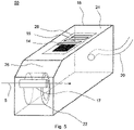
- Fig. 5 shows schematically a 3-dimensional hearing aid.
- the first antenna 15 is provided on a PCB 28 in the top of a first hearing aid housing 18.
- the first antenna is connected to a transceiver or radio 14.
- the battery 22 is provided closer to the second end 26 of the hearing aid housing 18 than to the first end of the hearing aid housing 24. It is seen that the second antenna 17 is provided behind the battery with respect to the first antenna 15, and thus between the battery 22 and the second end 26 of the hearing aid housing.
- Coupling element 20 connects the hearing aid housing 18 to the ear of the user (not shown), either by coupling sound through a coupling element in the form of an ear hook or a sound tube, or by coupling a signal to a receiver as positioned in the ear of a user via a coupling element 20 comprising an electrical signal path.
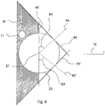
- Fig. 6 shows schematically a shadow effect of the battery as provided in the first hearing aid part, such as in the first hearing aid housing.
- the battery 22 is shown having a center axis 21 out of the plane of the paper and a further battery axis 48, as previously described.
- an antenna will be shielded by the battery from influence from an antenna at the other side of the battery.
- the second antenna 17 is provided behind the battery 22, for example in the shadow region 61, the second antenna 17 is shielded from the first antenna 15 by the battery 22.
- the shadow region 61 behind the battery may be defined as the region behind the center axis 21 of the battery 22, and more specifically, the shadow region may be defined as being the region behind the plane defined by the center axis 21 and the further battery axis 48.
- the shadow region 61 may be still further specified.
- an axis 62, 62' may be defined as an axis having an angle 63 to the further battery axis 48 towards the first antenna 15, the angle 63 being between 0 and 45 degrees.
- a tangent is provided, and the shadow region is defined by the plane defined by the center axis 21 and the further battery axis 48, and furthermore, by the plane of the tangents 64, 64'.
- a second antenna 17 provided in the shadow region 61 may thus be shielded with respect to the antenna 15 provided at the other side of the battery, opposite the shadow region 61.
Landscapes
- Engineering & Computer Science (AREA)
- Computer Networks & Wireless Communication (AREA)
- Health & Medical Sciences (AREA)
- General Health & Medical Sciences (AREA)
- Neurosurgery (AREA)
- Otolaryngology (AREA)
- Physics & Mathematics (AREA)
- Acoustics & Sound (AREA)
- Signal Processing (AREA)
- Support Of Aerials (AREA)
- Headphones And Earphones (AREA)
Description
- The present invention relates to antennas for hearing aids, in particular the present invention relates to hearing aids having two or more antennas, such as for example to a hearing aid having a combination of an electrical antenna and a magnetic antenna. The hearing aid may be used in a binaural hearing aid system. During operation, the hearing aid is worn at the ear of a user.
- Hearing aids are very small and delicate devices and comprise many electronic and metallic components contained in a housing small enough to fit in the ear canal of a human or be located behind the outer ear. The many electronic and metallic components in combination with the small size of the hearing aid housing impose high design constraints on radio frequency antennas to be used in hearing aids with wireless communication capabilities.
- Moreover, the antenna in the hearing aid has to be designed to achieve a satisfactory performance despite these limitations and other high design constraints imposed by the size of the hearing aid.
- Still further, in binaural hearing aid systems, the requirements to the quality of the communication between the hearing aids in the binaural hearing aid system are ever increasing, and include demands for low latency and low noise, increasing the requests for effective antennas in the hearing aids.
- In
US 2013/0188803 , an ear piece is disclosed having an antenna, wherein the antenna may be a wireless charging coil antenna, such as a coil antenna wrapped around the battery, and may be configured to enable inductive charging of the battery when the earpiece is placed in proximity of a charging station. - The document
US 2008/205678 discloses a hearing aid having a communication coil for data transmission particularly to a second hearing device and the communication coil may also be used for accepting energy and thereby charging the battery. -
US 2013/343584 discloses hearing assist devices and devices and services that are capable of providing external operational support to such hearing assist devices. The hearing assist device may include a plurality of sensors, processing logic, and an NFC transceiver. The hearing assist device may comprise a BLTE antenna. -
US 2013/0188803 A1 discloses an earpiece that enables efficient interaction between a user and a user's various wireless devices. An earpiece may include a first and second speaker, processor, memory battery, and various antennas. The first and second speakers may be configured and positioned on the earpiece so that when the earpiece is worn by a user the speakers do not block or enter an ear canal of the user. - It is an object of the present invention to provide a hearing aid with improved wireless communication capabilities, such as improved wireless communication capabilities between two hearing aids worn at opposite ears of the user, and/or between a hearing aid and an accessory device.
- In accordance with the present invention, the above-mentioned and other objects are obtained by a hearing aid, as according to claim 1.
- The battery is provided closer to a second end of the hearing aid than to a first end of the hearing aid, and the second antenna is provided between the battery, such as between a center axis of the battery, and the second end of the hearing aid. The first antenna may be provided between the battery, such as between the center axis of the battery, and the first end of the hearing.
- It is an advantage of the hearing aid that a first antenna and a second antenna are provided in the hearing aid, increasing the wireless communication capabilities of the hearing aid.
- According to a further aspect of the invention, a binaural hearing aid system is disclosed, the binaural hearing aid system comprising a first and a second hearing aid to be provided at a first and a second ear of the user, respectively, and wherein one or both of the hearing aids is a hearing aid as herein disclosed.
- The first antenna may be configured for radiation in a first frequency range, and the second antenna may be configured for radiation in a second frequency range.
- The first antenna is provided on a first side of the battery and the second antenna is provided on a second side of the battery, the first side of the battery and the second side of the battery being opposite sides of the battery, either transversely or longitudinally. The first antenna may be provided between the battery and the first end of the hearing aid.
- In one or more embodiments, the hearing aid comprises hearing aid electronic components including the signal processor. The hearing aid electronic components may be provided on a printed circuit board, and typically, the hearing aid electronic components are provided on the first side of the battery, such as between the battery and the first end of the hearing aid. Hereby, the battery provides shielding for the second antenna with respect to any noise caused by the first antenna and/or the hearing aid electronic components. Thus, the battery may act as a shielding element for the second antenna.
- The hearing aid may be any hearing aid, such as a hearing aid of the in-the-ear type, such as in-the-canal type, such as completely-in-the-canal type of hearing aid, etc., a hearing aid of the behind-the-ear type, of the receiver-in-the-ear type of hearing aid, etc.
- Typically, the hearing aid comprises a hearing aid part configured to be positioned behind the ear of a user and a coupling element for coupling sound or audio to the ear of a user.
- In one or more embodiments, the hearing aid comprises a first hearing aid part configured to be positioned behind the ear of a user, a second hearing aid part being configured to be positioned in the ear of a user, and a coupling element coupling the first hearing aid part and the second hearing aid part. The first hearing aid part may comprise the battery, and the second hearing aid part may comprise the speaker. Typically, the first hearing aid part comprises at least the microphone, the processing unit configured to process the audio signal for compensating a hearing loss of a user and the battery, whereas the speaker may be provided in the second hearing aid part. Typically, also the one or more wireless communication units are provided in the first hearing aid part. The first hearing aid part may be provided in a first hearing aid housing, and the second hearing aid part may be provided in a second hearing aid housing. Such hearing aids are typically referred to as receiver-in-the-ear hearing aids or RIE hearing aids.
- In one or more embodiments, the hearing aid comprises a first hearing aid part configured to be positioned behind the ear of a user and a coupling element, coupling the first hearing aid part and the ear canal of a user. Such hearing aids are typically referred to as behind-the-ear hearing aids, or BTE hearing aids.
- The coupling element may provide a processed sound to the ear, or the ear canal, of a user. The coupling element may comprise an electrical connection to a second hearing aid part comprising a speaker or a receiver for receiving processed audio signals from the signal processor provided in the first hearing aid part. The coupling element may comprise a sound tube or a thin tube for providing processed sound to the ear. The coupling element may comprise an ear hook for providing the processed sound to the ear of a user.
- In one or more embodiments, the coupling element may comprise at least a part of the first antenna. Thus, the first antenna may have at least a part of the antenna extending in the coupling element, and the antenna may have another part in the first hearing aid part and/or a further part in the second hearing aid part.
- In some embodiments however, the first antenna and the second antenna are provided within the first hearing aid part, such as within the first hearing aid housing. In other embodiments, the first antenna may protrude into the coupling element.
- A hearing aid housing, such as the first and/or second hearing aid housing, may comprise a hearing aid assembly, comprising components of the hearing aid, the hearing aid assembly being provided in the hearing aid housing. The hearing aid housing typically comprises a shell, such as a polymer or plastic shell, in a shape configured to be provided in the ear, in the ear-canal or behind the ear of a user. The coupling element is typically attachable to the hearing aid housing.
- The one or more wireless communications unit(s) are configured for wireless data communication, and in this respect interconnected with the first and/or second antenna for emission and reception of an electromagnetic field. Each of the one or more wireless communication unit may comprise a transmitter, a receiver, a transmitter-receiver pair, such as a transceiver, a radio unit, etc. The one or more wireless communication units may be configured for communication using any protocol as known for a person skilled in the art, including Bluetooth, WLAN standards, manufacture specific protocols, such as tailored proximity antenna protocols, such as proprietary protocols, such as low-power wireless communication protocols, RF communication protocols, magnetic induction protocols, etc. The one or more wireless communication units may be configured for communication using same communication protocols, or same type of communication protocols, or the one or more wireless communication units may be configured for communication using different communication protocols.
- In one or more embodiments, the first antenna has a longitudinal extension in a first direction. Thus, the first antenna may have an overall longitudinal extension in a first direction. The direction may indicate a line or path along which the first antenna is extending. For example, the overall length of the first antenna may be larger than the overall width of the first antenna indicating a longitudinal extension in the lengthwise direction.
- The first antenna may extend in one or more primary planes, such as extend substantially in a primary plane, such that for example at least 95%, 90%, 85% or 80% of the first antenna extends in one or more of the primary planes. The one or more primary planes may be parallel primary planes.
- Thus, for example, the first antenna may comprise a first antenna element extending along a first side of the hearing aid housing and a second antenna element extending along a second side of the hearing aid housing.
- The first side of the hearing aid housing may be a first longitudinal side of the hearing aid housing, and the second side of the hearing aid housing may be a second longitudinal side of the hearing aid housing. The first side may be opposite the second side.
- The second antenna has a longitudinal extension in a second direction, the second direction being parallel to, or being 0/180 degrees +/- 35 degrees, to an ear-to-ear axis of a user, when the hearing aid is worn in its operational position during use.
- The second direction may be orthogonal, such as 90 degrees +/- 35 degrees, to at least one of the primary planes, such as orthogonal, such as 90 degrees +/- 35 degrees, to one or more parallel primary planes.
- In one or more embodiments, the second direction is a direction which is 90 degrees +/- 35 degrees with respect to a side of the hearing aid, wherein the side is adjacent a head of a user during use.
- Thus, for example, the first antenna may substantially extend in a primary plane, whereas the second antenna may extend in a second direction being orthogonal to the primary plane.
- The first antenna may have a longitudinal extension in a first direction, whereas the second antenna may extend in a second direction being orthogonal to the first direction.
- In one or more embodiments, the first antenna is configured to have a first radiation pattern and the second antenna is configured to have a second radiation pattern, the first radiation pattern being different from the second radiation pattern.
- The near field pattern for the first and/or the second antenna may be a TM polarized near field. The first and/or second radiation pattern may be dominated by the E-field, so that a primary part of the overall electromagnetic field, such as more than 75%, such as more than 80%, such as more than 85%, such as more than 90% of the overall electromagnetic field, is contributed by the E-field.
- An advantage of the hearing aids as disclosed herein is that an improved wireless ear-to-ear communication may be achieved for most head sizes, shapes and amount of hair may be provided. Human heads and human ears vary in size and shape and also the amount of hair varies from person to person, and thus. Hearing aids adapted for wireless communications may be susceptible to impairments of for example the ear-to-ear communication due to e.g. the head of the user. Radio waves from a hearing aid at one side may have to travel through or around the head in order to reach the hearing aid at the other ear. Therefore, the human head may be perceived as an obstacle to the ear-to-ear communication. It is an advantage of the present invention that the antennas as provided in the hearing aids improve the ear-to-ear communication.
- In one or more embodiments, the first antenna is configured to operate in a first frequency range, and the second antenna is configured to operate in a second frequency range. The first frequency range may comprise higher frequencies than the second frequency range.
- The first antenna may be an electric antenna, and the second antenna may be a magnetic antenna.
- The first antenna may be configured to operate in a first frequency range, such as at a frequency above 800 MHz, such as at a frequency above 1 GHz, such as at a frequency of 2.4 GHz, such as at a frequency between 1.5 GHz and 3 GHz, during use. Thus, the first antenna may be configured for operation in ISM frequency band. The first antenna may be any antenna capable of operating at these frequencies, and the first antenna may be a resonant antenna, such as monopole antenna, such as a dipole antenna, etc. The resonant antenna may have a length of lambda/4 or any multiple thereof, lambda being the wavelength corresponding to the emitted electromagnetic field.
- The second antenna may be configured to operate at a second frequency range, such as at a frequency below 100 MHz, such as at below 30 MHz, such as below 15 MHz, during use. The second antenna may be configured to operate at a frequency range between 1 MHz and 100 MHz, such as between 1 MHz and 15 MHz, such as between 1MHz and 30 MHz, such as between 5 MHz and 30 MHz, such as between 5 MHz and 15 MHz, such as between 10 MHz and 11 MHz, such as between 10.2 MHz and 11 MHz.
- Especially, for a second antenna operating at a frequency below 10 MHz or below 100 MHz, is it advantageous that the battery is provided between the second antenna and the hearing aid electronic components, as the second antenna operating at such frequencies could be susceptible to noise originating from the hearing aid electronic components.
- In present day communication systems, numerous different communication systems communicate at or about 2.4 GHz, and thus there is also a significant noise in the frequency range at or about 2.4 GHz. It is an advantage of the present invention that for some applications for which the noise may be acceptable, for example for data communication, a first antenna, such as a first electrical antenna may be used. For other applications, in which a high noise level may impact the transmission significantly, a second antenna, such as a magnetic antenna may be used. For example, the second antenna may be used for streaming of audio.
- In one or more embodiments, the first antenna is configured for data communication at a first bit rate. In one or more embodiments, the second antenna is configured for data communication at a second bit rate, the second bit rate being larger than the first bit rate, such as by a
factor 10, such as by afactor 30, afactor 50, a factor 100, etc. - The second antenna may be configured for communication using magnetic induction. It is an advantage of using magnetic induction that typically low latency may be obtained. Especially when streaming audio is it of importance to keep the latency low, to avoid delays noticeable by a user. Typically, a delay of less than 100 ms, such as of less than 50 ms, such as of less than 25 ms, such as of less than 10 ms, such as of less than 5 ms, such as of less than 1 ms, is preferred.
- It is a further advantage of using magnetic induction for example for communicating between a first hearing aid and a second hearing aid in a binaural system that for the low frequencies, i.e. typically below 100 MHz, and corresponding long wavelengths, the head is not considered as a significant obstacle for the electromagnetic radiation emitted by the second antenna, thus, the reduction of electromagnetic radiation due to tissue absorption is reduced when the frequency is reduced.
- In the following the invention is described primarily with reference to a hearing aid, such as a binaural hearing aid. It is however envisaged that the disclosed features and embodiments may be used in combination with any aspect of the invention.
- The above and other features and advantages of the present invention will become more apparent to those of ordinary skill in the art by describing in detail exemplary embodiments thereof with reference to the attached drawings in which:
-
Fig. 1 shows a schematic view of a hearing aid according to an embodiment of the disclosure, -
Fig. 2 shows a BTE hearing aid with an ear hook according to the present disclosure, -
Fig. 3 shows a RIE hearing aid according to the present disclosure, -
Figs. 4a and 4b show schematically components of a hearing aid according to the present disclosure, -
Fig. 5 shows a three dimensional illustration of a hearing aid according to the present disclosure, and -
Fig. 6 illustrates a shadow effect of the battery. - The present invention will now be described more fully hereinafter with reference to the accompanying drawings, in which exemplary embodiments of the invention are shown. The invention may, however, be embodied in different forms and should not be construed as limited to the embodiments set forth herein. Rather, these embodiments are provided so that this disclosure will be thorough and complete, and will fully convey the scope of the invention to those skilled in the art.
- As used herein, the term "antenna" refers to an electrical or magnetic device which converts electric or magnetic power into radio waves. An electric antenna may comprise an electrically conductive material connected to e.g. a wireless communications unit, such as a radio chip, a receiver or a transmitter. A magnetic antenna, such as a magnetic loop antenna, comprises a coil of electrically conductive material wound around a core of magnetic material.
-
Fig. 1 shows a block-diagram of a hearing aid. InFig. 1 , thehearing aid 10 comprises amicrophone 11 for receiving incoming sound and converting it into an audio signal, i.e. a first audio signal. The first audio signal is provided to asignal processor 12 for processing the first audio signal into a second audio signal compensating a hearing loss of a user of the hearing aid. Areceiver 13 is connected to an output of thesignal processor 12 for converting the second audio signal into an output sound signal, e.g. a signal modified to compensate for a user's hearing impairment, and provides the output sound to aspeaker 13. Thus, the hearinginstrument signal processor 12 may comprise elements such as amplifiers, compressors and noise reduction systems etc. The hearing aid may further have a feedback loop for optimizing the output signal. The hearing aid has one or morewireless communication units 14,16 (e.g. a transceiver) for wireless communication, each interconnected with anantenna wireless communication units aid signal processor 12 andantennas signal processor 12, the one or morewireless communication units antennas hearing aid housing 18. In some embodiments, thespeaker 13 is provided in the first hearing aid part in thehearing aid housing 18, such as in behind-the-ear (BTE) hearing aids. In other embodiments, thespeaker 13 is provided in a secondhearing aid part 19, and for example provided in the ear of a user, such as in receiver-in-the-ear (RIE) hearing aids. - In
Fig. 2 , ahearing aid 10 is shown, thehearing aid 10 being configured to be positioned behind the ear of a user during use. Thehearing aid 10 is a behind-the-ear hearing aid. Thehearing aid 10 comprises ahearing aid housing 18 and acoupling element 20. InFig. 2 , the speaker 13 (not shown inFig. 2 ) is positioned in thehearing aid housing 18, and thecoupling element 20 couples the sound to the ear of a user. The hearing aid further comprises abattery 22 for supplying power to the electronic components, including the one or morewireless communication units signal processor 12, etc., of the hearing aid. It is seen that thebattery 22 is provided closer to asecond end 26 of thehearing aid housing 18 than to afirst end 24 of thehearing aid housing 18. The hearing aid furthermore comprises afirst antenna 15 and asecond antenna 17. - In
Fig. 2 , thefirst antenna 15 is provided within thehearing aid housing 18. It is however envisaged that the first antenna in some embodiments may extend into thecoupling element 20. Thefirst antenna 15 is an electric antenna, such as a monopole or dipole electric antenna. Thefirst antenna 15 may be provided on a printedcircuit board 28, and the printedcircuit board 28 may be a flexible printedcircuit board 28. Further electronic components may be provided on the printedcircuit board 28. - The
second antenna 17 is provided or positioned between the battery and a second end, such as between acenter axis 21 of thebattery 22 and thesecond end 26 of the hearing aid. Typically, thesecond antenna 17 is a magnetic antenna for establishing an inductive connection, and the second antenna may be a loop antenna, such as a magnetic loop antenna, a coil antenna, etc. - In some embodiments, the battery is a round flat type battery, such as a button cell type battery or coin cell type battery, and the center axis of the battery is an axis through a center of the battery from a first flat side of the battery to the other flat side of the battery. In some embodiments, a
further battery axis 27 is defined as an axis through the center of the battery and a point on the circumference of the battery, the further battery axis being orthogonal, such as 90 degrees +/- 15 degrees, such as 90 degrees +/- 35 degrees, to a top side and/or a bottom side of thehearing aid housing 18 at the position of the center of the battery. - The battery may be a round flat battery, such as a coin cell type battery type, and the battery may be provided with the flat sides along longitudinal axes of the
hearing aid housing 18, such as along the longitudinal axes of the firsthearing aid part 33. - The
second antenna 17 may be provided so that both thecenter axis 21 of the battery and thefurther battery axis 27 is on one side of thesecond antenna 17, and thesecond end 26 of thehearing aid housing 33, i.e. the first part of thehearing aid housing 33, is on another side of thesecond antenna 17. Thus, thesecond antenna 17 may be positioned between a center plane of the battery, the center plane being established by thecenter axis 21 of the battery and thefurther battery axis 27, and thesecond end 26 of thehearing aid housing 33. - It has been found that hereby, a shadow effect of the battery reduces interference between the
first antenna 15 and thesecond antenna 17. - In
Fig. 3 , anotherhearing aid 30 is shown. InFig. 3 , like numerals represents the same elements as shown inFig. 2 . However, inFig. 3 , the hearing aid is a hearing aid having a firsthearing aid part 33 being configured to be positioned behind the ear of a user, and a secondhearing aid part 31 being configured to be positioned in the ear canal of a user. Acoupling element 20 connects the first hearing aid part 33' and the secondhearing aid part 31. Thehearing aid part 31 is shown as provided in housing orshell 31. InFig. 3 , afirst part 15a of thefirst antenna 15 is provided in the firsthearing aid part 33, and thus in the firsthearing aid housing 33, while anotherpart 15b of thefirst antenna 15 is provided in thecoupling element 20. Thefirst part 15a of thefirst antenna 15 is connected to a first wireless communication unit, such as a transceiver (not shown inFig. 3 ) in the firsthearing aid part 33. - The
second antenna 17 is typically connected to a second wireless communication unit, such as a transceiver, different from the first wireless communication unit. -
Figs. 4a and 4b show schematically a hearing aid according to the present disclosure.Fig. 4a shows a side view of a hearing aid, such as of afirst part 41 of ahearing aid 40. The first part of the hearing aid, i.e. the first hearing aid housing orpart 41, has alongitudinal side 44 and atop side 49. The firsthearing aid part 41 has afirst end 24 and asecond end 26. Thehearing aid 40 has abattery 42, afirst antenna 45 and asecond antenna 47. It is seen that the battery is provided in the firsthearing aid part 41 closer to thesecond end 26 of thefirst part 41 of the hearing aid, than to thefirst end 26 of the firsthearing aid part 41. Thus, afirst distance 2 from thesecond end 26 to thecenter axis 43 of the battery is smaller than asecond distance 4 from thefirst end 24 to thecenter axis 43 of the battery. - The
first antenna 45 extends along a side, such as alongitudinal side 44, of the first hearing aid part, or hearing aid housing, 41. Thesecond antenna 47 is a magnetic loop antenna which has alongitudinal axis 46 out of the plane of the paper. It is seen that thecenter axis 43 of thebattery 42 is out of the plane of the paper and thus parallel, such as parallel +/- 15 degrees, such as parallel +/- 35 degrees, with thelongitudinal axis 46 of themagnetic loop antenna 47. - The
further battery axis 48 is seen as being orthogonal to thetop side 49 of the firsthearing aid housing 41, such as having an angle of 90 degrees +/- 15 degrees, such as 90 degrees +/- 35 degrees, to a top side and/or a bottom side of thehearing aid housing 41 at the position of the center of the battery. - In
Fig. 4b , thehearing aid 40 is seen from an end view, from thesecond end 26 of the firsthearing aid housing 41. Thehearing aid housing 41 has anend side 43 of the housing or shell of thehearing aid housing 41. Thebattery 22 is seen to be positioned closer to thesecond end 26 than to the first end (not shown inFig. 4b ) and thesecond antenna 47 is positioned between thesecond end 26 and thebattery 22. Typically, thesecond antenna 47 comprises amagnetic core 38, in the form of a rod of a magnetic material, andwindings 39 of an electrical conductor wound around themagnetic core 38. The magnetic core has alongitudinal axis 5. - The
second antenna 47 may be provided so that therod 38 of magnetic material is provided transversal in the firsthearing aid housing 41, thus so that the second antenna has a longitudinal direction orthogonal tolongitudinal sides 44 of the first hearing aid housing. Thelongitudinal axis 5 may thus form an angle with the longitudinal sides of the first hearing aid housing of 90 degrees, such as of 90 degrees +/- 15 degrees, such as of 90 degrees +/- 35 degrees. Thesecond antenna 47 may primarily radiate through end surfaces 42. Themagnetic core 38 and thewindings 39 may be provided in a housing (not shown), such as a housing shielding longitudinal parts of thesecond antenna 47. -
Fig. 5 shows schematically a 3-dimensional hearing aid. Thefirst antenna 15 is provided on aPCB 28 in the top of a firsthearing aid housing 18. The first antenna is connected to a transceiver orradio 14. Thebattery 22 is provided closer to thesecond end 26 of thehearing aid housing 18 than to the first end of thehearing aid housing 24. It is seen that thesecond antenna 17 is provided behind the battery with respect to thefirst antenna 15, and thus between thebattery 22 and thesecond end 26 of the hearing aid housing. Couplingelement 20 connects thehearing aid housing 18 to the ear of the user (not shown), either by coupling sound through a coupling element in the form of an ear hook or a sound tube, or by coupling a signal to a receiver as positioned in the ear of a user via acoupling element 20 comprising an electrical signal path. -
Fig. 6 shows schematically a shadow effect of the battery as provided in the first hearing aid part, such as in the first hearing aid housing. InFig. 6 , thebattery 22 is shown having acenter axis 21 out of the plane of the paper and afurther battery axis 48, as previously described. At one side of the battery, an antenna will be shielded by the battery from influence from an antenna at the other side of the battery. Thus, if thesecond antenna 17 is provided behind thebattery 22, for example in theshadow region 61, thesecond antenna 17 is shielded from thefirst antenna 15 by thebattery 22. - The
shadow region 61 behind the battery may be defined as the region behind thecenter axis 21 of thebattery 22, and more specifically, the shadow region may be defined as being the region behind the plane defined by thecenter axis 21 and thefurther battery axis 48. Theshadow region 61 may be still further specified. Thus, anaxis 62, 62' may be defined as an axis having anangle 63 to thefurther battery axis 48 towards thefirst antenna 15, theangle 63 being between 0 and 45 degrees. At the intersection between theaxis 62, 62' and the circumference of the battery, a tangent is provided, and the shadow region is defined by the plane defined by thecenter axis 21 and thefurther battery axis 48, and furthermore, by the plane of thetangents 64, 64'. Asecond antenna 17 provided in theshadow region 61 may thus be shielded with respect to theantenna 15 provided at the other side of the battery, opposite theshadow region 61. - Although particular embodiments have been shown and described, it will be understood that it is not intended to limit the claimed inventions to the preferred embodiments, and it will be obvious to those skilled in the art that various changes and modifications may be made without departing from the scope of the claimed invention, as defined in claim 1.
- The specification and drawings are, accordingly, to be regarded in an illustrative rather than restrictive sense.
Claims (13)
- A hearing aid (10) having a hearing aid housing (18), the hearing aid housing (18) having a first end (24) and a second end (26) and comprisinga microphone (11) configured to receive an audio signal,a battery (22) provided closer to the second end (26) of the hearing aid housing (18) than to the first end (24) of the hearing aid housing (18),electronic components including a processing unit (12) configured to process the audio signal for compensating a hearing loss of a user, the electroniccomponents being provided between the battery (22) and the first end (24) of the hearing aid housing (18),one or more wireless communication units (14, 16) for wireless communication, each of the one or more wireless communication unit comprising a transmitter-receiver pair,at least a part of a first antenna (15) for emission and reception of an electromagnetic field being interconnected with one of the one or more wireless communication units (14, 16), the first antenna (15) being an electric antenna, anda second antenna (17) for emission and reception of an electromagnetic field being interconnected with one of the one or more wireless communication units (14, 16), the second antenna (17) being a magnetic antenna comprising a coil of electrically conductive material wound around a core of magnetic material, the second antenna (17) having a longitudinal extension in a second direction parallel to +/- 35 degrees to an ear-to-ear axis of a user, when the hearing aid (10) is worn in its operational position during use,wherein the second antenna (17) is provided between the battery (22) and the second end (26) of the hearing aid housing (18),wherein the first antenna (15) is provided on a first side of the battery (22) and the second antenna (17) is provided on a second side of the battery (22), the first side of the battery (22) and the second side of the battery being opposite sides of the battery (22).
- A hearing aid (10) according to claim 1, comprising- a first hearing aid part (33) configured to be positioned in the hearing aid housing (18) behind the ear of a user,- a second hearing aid part (31) being configured to be positioned in the ear of a user, and- a coupling element (20) coupling the first hearing aid part (33) and the second hearing aid part (31).
- A hearing aid (10) according to claim 2, wherein the first hearing aid part (33) comprises the battery (22), and wherein the second hearing aid part (31) comprises a speaker (13).
- A hearing aid (10) according to claim 2, wherein the coupling element (20) comprises at least a part of the first antenna (15).
- A hearing aid (10) according to any of the preceding claims, wherein the second antenna (17) has a longitudinal extension in a second direction.
- A hearing aid (10) according to claim 5, wherein the first antenna (electric) is provided in one or more planes, the one or more planes being orthogonal, such as 90 degrees +/- 35 degrees, to the second direction.
- A hearing aid (10) according to any of the preceding claims, wherein the first antenna (15) is configured for radiation in a first frequency range, and the second antenna (17) is configured for radiation in a second frequency range.
- A hearing aid (10) according to any of the preceding claims, wherein the first antenna (15) is configured to operate at a frequency above 800 MHz, such as at a frequency above 1 GHz, such as at a frequency of 2.4 GHz, during use.
- A hearing aid (10) according to any of the preceding claims, wherein the second antenna (17) is configured to operate at a frequency below 100 MHz, such as at below 10 MHz, during use.
- A hearing aid (10) according to any of the preceding claims, wherein the second antenna (17) is configured to operate at a frequency between 1 MHz and 100 MHz.
- A hearing aid (10) according to any of the preceding claims, wherein the first antenna (15) is configured for data communication at a first bit rate.
- A hearing aid (10) according to claim 11, wherein the second antenna (17) is configured for data communication at a second bit rate, the second bit rate being larger than the first bit rate, such as by a factor 10.
- A binaural hearing aid system comprising a first and a second hearing aid (10) to be provided at a first and a second ear of the user, respectively, wherein one or both of the hearing aids is a hearing aid (10) according to any of claims 1-12.
Priority Applications (2)
| Application Number | Priority Date | Filing Date | Title |
|---|---|---|---|
| DK19157184.3T DK3503589T3 (en) | 2015-06-22 | 2015-06-22 | Hearing aid with combined antennas |
| EP19157184.3A EP3503589B1 (en) | 2015-06-22 | 2015-06-22 | A hearing aid having combined antennas |
Applications Claiming Priority (2)
| Application Number | Priority Date | Filing Date | Title |
|---|---|---|---|
| EP15001843.0A EP3110170B1 (en) | 2015-06-22 | 2015-06-22 | A hearing aid having combined antennas |
| EP19157184.3A EP3503589B1 (en) | 2015-06-22 | 2015-06-22 | A hearing aid having combined antennas |
Related Parent Applications (1)
| Application Number | Title | Priority Date | Filing Date |
|---|---|---|---|
| EP15001843.0A Division EP3110170B1 (en) | 2015-06-22 | 2015-06-22 | A hearing aid having combined antennas |
Publications (2)
| Publication Number | Publication Date |
|---|---|
| EP3503589A1 EP3503589A1 (en) | 2019-06-26 |
| EP3503589B1 true EP3503589B1 (en) | 2022-07-20 |
Family
ID=53483640
Family Applications (2)
| Application Number | Title | Priority Date | Filing Date |
|---|---|---|---|
| EP15001843.0A Revoked EP3110170B1 (en) | 2015-06-22 | 2015-06-22 | A hearing aid having combined antennas |
| EP19157184.3A Active EP3503589B1 (en) | 2015-06-22 | 2015-06-22 | A hearing aid having combined antennas |
Family Applications Before (1)
| Application Number | Title | Priority Date | Filing Date |
|---|---|---|---|
| EP15001843.0A Revoked EP3110170B1 (en) | 2015-06-22 | 2015-06-22 | A hearing aid having combined antennas |
Country Status (2)
| Country | Link |
|---|---|
| EP (2) | EP3110170B1 (en) |
| DK (2) | DK3110170T3 (en) |
Families Citing this family (2)
| Publication number | Priority date | Publication date | Assignee | Title |
|---|---|---|---|---|
| WO2019130843A1 (en) | 2017-12-29 | 2019-07-04 | ソニー株式会社 | Acoustic output device |
| EP3826329A1 (en) | 2019-11-21 | 2021-05-26 | Oticon A/s | Device with coil |
Citations (17)
| Publication number | Priority date | Publication date | Assignee | Title |
|---|---|---|---|---|
| CH691944A5 (en) | 1997-10-07 | 2001-11-30 | Phonak Comm Ag | Hearing aid with external FM transmitter includes receiver mounted behind ear, and amplifier and speaker accommodated within ear |
| US20080205678A1 (en) | 2007-02-26 | 2008-08-28 | Siemens Audiologische Technik Gmbh | Hearing apparatus with a special energy acceptance system and corresponding method |
| EP1973379A2 (en) | 2007-03-21 | 2008-09-24 | Starkey Laboratories, Inc. | System for providing power to a hearing assistance device |
| EP2026406A1 (en) | 2007-08-14 | 2009-02-18 | Oticon A/S | Multipurpose antenna unit |
| US20090231204A1 (en) | 2007-12-06 | 2009-09-17 | Ami Semiconductor, Inc. | Miniature antenna for wireless communications |
| US20090285426A1 (en) | 2008-05-13 | 2009-11-19 | Mihail Boguslavskij | Hearing Aid and Energy Charger as well as Associated Method |
| US20090296967A1 (en) | 2008-05-30 | 2009-12-03 | Matthias Mullenborn | Hearing aid system with a low power wireless link between a hearing instrument and a telephone |
| US20090315787A1 (en) | 2006-07-28 | 2009-12-24 | Siemens Audiologische Technik Gmbh | Antenna arrangement for hearing device applications |
| US20100054513A1 (en) | 2008-09-03 | 2010-03-04 | Siemens Medical Instruments Pte. Ltd. | Hearing aid with an attenuation element |
| US20110194717A1 (en) | 2008-09-26 | 2011-08-11 | Oticon A/S | Hearing aid with exchangeable shell parts and wireless communication |
| EP2403273A1 (en) | 2010-07-03 | 2012-01-04 | Starkey Laboratories, Inc. | Multi-mode radio for hearing assistance devices |
| US20120093324A1 (en) | 2010-10-12 | 2012-04-19 | Gn Resound A/S | Hearing Aid with an Antenna |
| EP2498514A1 (en) | 2011-03-08 | 2012-09-12 | Nxp B.V. | A hearing device and methods of operating a hearing device |
| US20130188803A1 (en) | 2012-01-20 | 2013-07-25 | Qualcomm Incorporated | Earpiece |
| US20130273862A1 (en) | 2012-04-16 | 2013-10-17 | Motorola Mobility, Inc. | Reduction of magnetic field noise via management of current draw from a power source |
| WO2014086392A1 (en) | 2012-12-04 | 2014-06-12 | Phonak Ag | Hearing instrument comprising two antennas |
| EP2835863A1 (en) | 2013-08-09 | 2015-02-11 | Oticon A/s | RF antenna and hearing device with RF antenna |
Family Cites Families (3)
| Publication number | Priority date | Publication date | Assignee | Title |
|---|---|---|---|---|
| US8155335B2 (en) * | 2007-03-14 | 2012-04-10 | Phillip Rutschman | Headset having wirelessly linked earpieces |
| US9185501B2 (en) * | 2012-06-20 | 2015-11-10 | Broadcom Corporation | Container-located information transfer module |
| KR102000513B1 (en) * | 2013-04-16 | 2019-07-17 | 삼성전자주식회사 | Hearing apparatus comprising switchable coil for operation mode |
-
2015
- 2015-06-22 EP EP15001843.0A patent/EP3110170B1/en not_active Revoked
- 2015-06-22 DK DK15001843.0T patent/DK3110170T3/en active
- 2015-06-22 EP EP19157184.3A patent/EP3503589B1/en active Active
- 2015-06-22 DK DK19157184.3T patent/DK3503589T3/en active
Patent Citations (17)
| Publication number | Priority date | Publication date | Assignee | Title |
|---|---|---|---|---|
| CH691944A5 (en) | 1997-10-07 | 2001-11-30 | Phonak Comm Ag | Hearing aid with external FM transmitter includes receiver mounted behind ear, and amplifier and speaker accommodated within ear |
| US20090315787A1 (en) | 2006-07-28 | 2009-12-24 | Siemens Audiologische Technik Gmbh | Antenna arrangement for hearing device applications |
| US20080205678A1 (en) | 2007-02-26 | 2008-08-28 | Siemens Audiologische Technik Gmbh | Hearing apparatus with a special energy acceptance system and corresponding method |
| EP1973379A2 (en) | 2007-03-21 | 2008-09-24 | Starkey Laboratories, Inc. | System for providing power to a hearing assistance device |
| EP2026406A1 (en) | 2007-08-14 | 2009-02-18 | Oticon A/S | Multipurpose antenna unit |
| US20090231204A1 (en) | 2007-12-06 | 2009-09-17 | Ami Semiconductor, Inc. | Miniature antenna for wireless communications |
| US20090285426A1 (en) | 2008-05-13 | 2009-11-19 | Mihail Boguslavskij | Hearing Aid and Energy Charger as well as Associated Method |
| US20090296967A1 (en) | 2008-05-30 | 2009-12-03 | Matthias Mullenborn | Hearing aid system with a low power wireless link between a hearing instrument and a telephone |
| US20100054513A1 (en) | 2008-09-03 | 2010-03-04 | Siemens Medical Instruments Pte. Ltd. | Hearing aid with an attenuation element |
| US20110194717A1 (en) | 2008-09-26 | 2011-08-11 | Oticon A/S | Hearing aid with exchangeable shell parts and wireless communication |
| EP2403273A1 (en) | 2010-07-03 | 2012-01-04 | Starkey Laboratories, Inc. | Multi-mode radio for hearing assistance devices |
| US20120093324A1 (en) | 2010-10-12 | 2012-04-19 | Gn Resound A/S | Hearing Aid with an Antenna |
| EP2498514A1 (en) | 2011-03-08 | 2012-09-12 | Nxp B.V. | A hearing device and methods of operating a hearing device |
| US20130188803A1 (en) | 2012-01-20 | 2013-07-25 | Qualcomm Incorporated | Earpiece |
| US20130273862A1 (en) | 2012-04-16 | 2013-10-17 | Motorola Mobility, Inc. | Reduction of magnetic field noise via management of current draw from a power source |
| WO2014086392A1 (en) | 2012-12-04 | 2014-06-12 | Phonak Ag | Hearing instrument comprising two antennas |
| EP2835863A1 (en) | 2013-08-09 | 2015-02-11 | Oticon A/s | RF antenna and hearing device with RF antenna |
Also Published As
| Publication number | Publication date |
|---|---|
| DK3503589T3 (en) | 2022-09-12 |
| EP3110170A1 (en) | 2016-12-28 |
| EP3503589A1 (en) | 2019-06-26 |
| DK3110170T3 (en) | 2019-04-23 |
| EP3110170B1 (en) | 2019-02-20 |
Similar Documents
| Publication | Publication Date | Title |
|---|---|---|
| US11172315B2 (en) | Hearing aid having combined antennas | |
| US9609443B2 (en) | In-the-ear hearing aid having combined antennas | |
| US10667064B2 (en) | ITE hearing aid with improved wireless communication | |
| US9877119B2 (en) | Hearing aid with antenna on printed circuit board | |
| EP3122071B1 (en) | An in-the-ear hearing aid having combined antennas | |
| US11290828B2 (en) | Hearing device with antenna functionality in supporting structure | |
| EP3503589B1 (en) | A hearing aid having combined antennas | |
| EP3185583B1 (en) | Hearing aid with antenna on printed circuit board | |
| EP3174314B1 (en) | Ite hearing aid with improved wireless communication | |
| DK201570485A1 (en) | An in-the-ear hearing aid having combined antennas | |
| DK201570757A1 (en) | Ite hearing aid with improved wireless communication | |
| DK201570841A1 (en) | Hearing aid with antenna on printed circuit board |
Legal Events
| Date | Code | Title | Description |
|---|---|---|---|
| PUAI | Public reference made under article 153(3) epc to a published international application that has entered the european phase |
Free format text: ORIGINAL CODE: 0009012 |
|
| STAA | Information on the status of an ep patent application or granted ep patent |
Free format text: STATUS: THE APPLICATION HAS BEEN PUBLISHED |
|
| AC | Divisional application: reference to earlier application |
Ref document number: 3110170 Country of ref document: EP Kind code of ref document: P |
|
| AK | Designated contracting states |
Kind code of ref document: A1 Designated state(s): AL AT BE BG CH CY CZ DE DK EE ES FI FR GB GR HR HU IE IS IT LI LT LU LV MC MK MT NL NO PL PT RO RS SE SI SK SM TR |
|
| STAA | Information on the status of an ep patent application or granted ep patent |
Free format text: STATUS: REQUEST FOR EXAMINATION WAS MADE |
|
| 17P | Request for examination filed |
Effective date: 20191218 |
|
| RBV | Designated contracting states (corrected) |
Designated state(s): AL AT BE BG CH CY CZ DE DK EE ES FI FR GB GR HR HU IE IS IT LI LT LU LV MC MK MT NL NO PL PT RO RS SE SI SK SM TR |
|
| STAA | Information on the status of an ep patent application or granted ep patent |
Free format text: STATUS: EXAMINATION IS IN PROGRESS |
|
| 17Q | First examination report despatched |
Effective date: 20200128 |
|
| STAA | Information on the status of an ep patent application or granted ep patent |
Free format text: STATUS: EXAMINATION IS IN PROGRESS |
|
| GRAP | Despatch of communication of intention to grant a patent |
Free format text: ORIGINAL CODE: EPIDOSNIGR1 |
|
| STAA | Information on the status of an ep patent application or granted ep patent |
Free format text: STATUS: GRANT OF PATENT IS INTENDED |
|
| INTG | Intention to grant announced |
Effective date: 20220317 |
|
| GRAS | Grant fee paid |
Free format text: ORIGINAL CODE: EPIDOSNIGR3 |
|
| GRAA | (expected) grant |
Free format text: ORIGINAL CODE: 0009210 |
|
| STAA | Information on the status of an ep patent application or granted ep patent |
Free format text: STATUS: THE PATENT HAS BEEN GRANTED |
|
| AC | Divisional application: reference to earlier application |
Ref document number: 3110170 Country of ref document: EP Kind code of ref document: P |
|
| AK | Designated contracting states |
Kind code of ref document: B1 Designated state(s): AL AT BE BG CH CY CZ DE DK EE ES FI FR GB GR HR HU IE IS IT LI LT LU LV MC MK MT NL NO PL PT RO RS SE SI SK SM TR |
|
| REG | Reference to a national code |
Ref country code: CH Ref legal event code: EP |
|
| REG | Reference to a national code |
Ref country code: DE Ref legal event code: R096 Ref document number: 602015079991 Country of ref document: DE |
|
| REG | Reference to a national code |
Ref country code: AT Ref legal event code: REF Ref document number: 1506341 Country of ref document: AT Kind code of ref document: T Effective date: 20220815 |
|
| REG | Reference to a national code |
Ref country code: IE Ref legal event code: FG4D |
|
| REG | Reference to a national code |
Ref country code: DK Ref legal event code: T3 Effective date: 20220907 |
|
| REG | Reference to a national code |
Ref country code: LT Ref legal event code: MG9D |
|
| REG | Reference to a national code |
Ref country code: NL Ref legal event code: MP Effective date: 20220720 |
|
| PG25 | Lapsed in a contracting state [announced via postgrant information from national office to epo] |
Ref country code: SE Free format text: LAPSE BECAUSE OF FAILURE TO SUBMIT A TRANSLATION OF THE DESCRIPTION OR TO PAY THE FEE WITHIN THE PRESCRIBED TIME-LIMIT Effective date: 20220720 Ref country code: RS Free format text: LAPSE BECAUSE OF FAILURE TO SUBMIT A TRANSLATION OF THE DESCRIPTION OR TO PAY THE FEE WITHIN THE PRESCRIBED TIME-LIMIT Effective date: 20220720 Ref country code: PT Free format text: LAPSE BECAUSE OF FAILURE TO SUBMIT A TRANSLATION OF THE DESCRIPTION OR TO PAY THE FEE WITHIN THE PRESCRIBED TIME-LIMIT Effective date: 20221121 Ref country code: NO Free format text: LAPSE BECAUSE OF FAILURE TO SUBMIT A TRANSLATION OF THE DESCRIPTION OR TO PAY THE FEE WITHIN THE PRESCRIBED TIME-LIMIT Effective date: 20221020 Ref country code: NL Free format text: LAPSE BECAUSE OF FAILURE TO SUBMIT A TRANSLATION OF THE DESCRIPTION OR TO PAY THE FEE WITHIN THE PRESCRIBED TIME-LIMIT Effective date: 20220720 Ref country code: LV Free format text: LAPSE BECAUSE OF FAILURE TO SUBMIT A TRANSLATION OF THE DESCRIPTION OR TO PAY THE FEE WITHIN THE PRESCRIBED TIME-LIMIT Effective date: 20220720 Ref country code: LT Free format text: LAPSE BECAUSE OF FAILURE TO SUBMIT A TRANSLATION OF THE DESCRIPTION OR TO PAY THE FEE WITHIN THE PRESCRIBED TIME-LIMIT Effective date: 20220720 Ref country code: FI Free format text: LAPSE BECAUSE OF FAILURE TO SUBMIT A TRANSLATION OF THE DESCRIPTION OR TO PAY THE FEE WITHIN THE PRESCRIBED TIME-LIMIT Effective date: 20220720 Ref country code: ES Free format text: LAPSE BECAUSE OF FAILURE TO SUBMIT A TRANSLATION OF THE DESCRIPTION OR TO PAY THE FEE WITHIN THE PRESCRIBED TIME-LIMIT Effective date: 20220720 |
|
| REG | Reference to a national code |
Ref country code: AT Ref legal event code: MK05 Ref document number: 1506341 Country of ref document: AT Kind code of ref document: T Effective date: 20220720 |
|
| PG25 | Lapsed in a contracting state [announced via postgrant information from national office to epo] |
Ref country code: PL Free format text: LAPSE BECAUSE OF FAILURE TO SUBMIT A TRANSLATION OF THE DESCRIPTION OR TO PAY THE FEE WITHIN THE PRESCRIBED TIME-LIMIT Effective date: 20220720 Ref country code: IS Free format text: LAPSE BECAUSE OF FAILURE TO SUBMIT A TRANSLATION OF THE DESCRIPTION OR TO PAY THE FEE WITHIN THE PRESCRIBED TIME-LIMIT Effective date: 20221120 Ref country code: HR Free format text: LAPSE BECAUSE OF FAILURE TO SUBMIT A TRANSLATION OF THE DESCRIPTION OR TO PAY THE FEE WITHIN THE PRESCRIBED TIME-LIMIT Effective date: 20220720 Ref country code: GR Free format text: LAPSE BECAUSE OF FAILURE TO SUBMIT A TRANSLATION OF THE DESCRIPTION OR TO PAY THE FEE WITHIN THE PRESCRIBED TIME-LIMIT Effective date: 20221021 |
|
| REG | Reference to a national code |
Ref country code: DE Ref legal event code: R026 Ref document number: 602015079991 Country of ref document: DE |
|
| PG25 | Lapsed in a contracting state [announced via postgrant information from national office to epo] |
Ref country code: SM Free format text: LAPSE BECAUSE OF FAILURE TO SUBMIT A TRANSLATION OF THE DESCRIPTION OR TO PAY THE FEE WITHIN THE PRESCRIBED TIME-LIMIT Effective date: 20220720 Ref country code: RO Free format text: LAPSE BECAUSE OF FAILURE TO SUBMIT A TRANSLATION OF THE DESCRIPTION OR TO PAY THE FEE WITHIN THE PRESCRIBED TIME-LIMIT Effective date: 20220720 Ref country code: CZ Free format text: LAPSE BECAUSE OF FAILURE TO SUBMIT A TRANSLATION OF THE DESCRIPTION OR TO PAY THE FEE WITHIN THE PRESCRIBED TIME-LIMIT Effective date: 20220720 Ref country code: AT Free format text: LAPSE BECAUSE OF FAILURE TO SUBMIT A TRANSLATION OF THE DESCRIPTION OR TO PAY THE FEE WITHIN THE PRESCRIBED TIME-LIMIT Effective date: 20220720 |
|
| PLBI | Opposition filed |
Free format text: ORIGINAL CODE: 0009260 |
|
| PLAX | Notice of opposition and request to file observation + time limit sent |
Free format text: ORIGINAL CODE: EPIDOSNOBS2 |
|
| 26 | Opposition filed |
Opponent name: OTICON A/S / WIDEX A/S Effective date: 20230420 |
|
| PG25 | Lapsed in a contracting state [announced via postgrant information from national office to epo] |
Ref country code: SK Free format text: LAPSE BECAUSE OF FAILURE TO SUBMIT A TRANSLATION OF THE DESCRIPTION OR TO PAY THE FEE WITHIN THE PRESCRIBED TIME-LIMIT Effective date: 20220720 Ref country code: EE Free format text: LAPSE BECAUSE OF FAILURE TO SUBMIT A TRANSLATION OF THE DESCRIPTION OR TO PAY THE FEE WITHIN THE PRESCRIBED TIME-LIMIT Effective date: 20220720 |
|
| PG25 | Lapsed in a contracting state [announced via postgrant information from national office to epo] |
Ref country code: AL Free format text: LAPSE BECAUSE OF FAILURE TO SUBMIT A TRANSLATION OF THE DESCRIPTION OR TO PAY THE FEE WITHIN THE PRESCRIBED TIME-LIMIT Effective date: 20220720 |
|
| P01 | Opt-out of the competence of the unified patent court (upc) registered |
Effective date: 20230525 |
|
| PG25 | Lapsed in a contracting state [announced via postgrant information from national office to epo] |
Ref country code: SI Free format text: LAPSE BECAUSE OF FAILURE TO SUBMIT A TRANSLATION OF THE DESCRIPTION OR TO PAY THE FEE WITHIN THE PRESCRIBED TIME-LIMIT Effective date: 20220720 |
|
| PLBB | Reply of patent proprietor to notice(s) of opposition received |
Free format text: ORIGINAL CODE: EPIDOSNOBS3 |
|
| PGFP | Annual fee paid to national office [announced via postgrant information from national office to epo] |
Ref country code: CH Payment date: 20230702 Year of fee payment: 9 |
|
| PG25 | Lapsed in a contracting state [announced via postgrant information from national office to epo] |
Ref country code: MC Free format text: LAPSE BECAUSE OF FAILURE TO SUBMIT A TRANSLATION OF THE DESCRIPTION OR TO PAY THE FEE WITHIN THE PRESCRIBED TIME-LIMIT Effective date: 20220720 |
|
| PG25 | Lapsed in a contracting state [announced via postgrant information from national office to epo] |
Ref country code: MC Free format text: LAPSE BECAUSE OF FAILURE TO SUBMIT A TRANSLATION OF THE DESCRIPTION OR TO PAY THE FEE WITHIN THE PRESCRIBED TIME-LIMIT Effective date: 20220720 |
|
| REG | Reference to a national code |
Ref country code: BE Ref legal event code: MM Effective date: 20230630 |
|
| PG25 | Lapsed in a contracting state [announced via postgrant information from national office to epo] |
Ref country code: LU Free format text: LAPSE BECAUSE OF NON-PAYMENT OF DUE FEES Effective date: 20230622 |
|
| REG | Reference to a national code |
Ref country code: IE Ref legal event code: MM4A |
|
| PG25 | Lapsed in a contracting state [announced via postgrant information from national office to epo] |
Ref country code: LU Free format text: LAPSE BECAUSE OF NON-PAYMENT OF DUE FEES Effective date: 20230622 |
|
| PG25 | Lapsed in a contracting state [announced via postgrant information from national office to epo] |
Ref country code: IE Free format text: LAPSE BECAUSE OF NON-PAYMENT OF DUE FEES Effective date: 20230622 |
|
| PG25 | Lapsed in a contracting state [announced via postgrant information from national office to epo] |
Ref country code: IE Free format text: LAPSE BECAUSE OF NON-PAYMENT OF DUE FEES Effective date: 20230622 |
|
| PG25 | Lapsed in a contracting state [announced via postgrant information from national office to epo] |
Ref country code: IT Free format text: LAPSE BECAUSE OF FAILURE TO SUBMIT A TRANSLATION OF THE DESCRIPTION OR TO PAY THE FEE WITHIN THE PRESCRIBED TIME-LIMIT Effective date: 20220720 Ref country code: BE Free format text: LAPSE BECAUSE OF NON-PAYMENT OF DUE FEES Effective date: 20230630 |
|
| PGFP | Annual fee paid to national office [announced via postgrant information from national office to epo] |
Ref country code: GB Payment date: 20240618 Year of fee payment: 10 |
|
| PGFP | Annual fee paid to national office [announced via postgrant information from national office to epo] |
Ref country code: DE Payment date: 20240612 Year of fee payment: 10 |
|
| PGFP | Annual fee paid to national office [announced via postgrant information from national office to epo] |
Ref country code: DK Payment date: 20240619 Year of fee payment: 10 |
|
| PGFP | Annual fee paid to national office [announced via postgrant information from national office to epo] |
Ref country code: FR Payment date: 20240618 Year of fee payment: 10 |