EP3503586A1 - Sound generation device - Google Patents
Sound generation device Download PDFInfo
- Publication number
- EP3503586A1 EP3503586A1 EP17841244.1A EP17841244A EP3503586A1 EP 3503586 A1 EP3503586 A1 EP 3503586A1 EP 17841244 A EP17841244 A EP 17841244A EP 3503586 A1 EP3503586 A1 EP 3503586A1
- Authority
- EP
- European Patent Office
- Prior art keywords
- yoke
- sound
- armature
- case
- producing device
- Prior art date
- Legal status (The legal status is an assumption and is not a legal conclusion. Google has not performed a legal analysis and makes no representation as to the accuracy of the status listed.)
- Withdrawn
Links
Images




Classifications
-
- H—ELECTRICITY
- H04—ELECTRIC COMMUNICATION TECHNIQUE
- H04R—LOUDSPEAKERS, MICROPHONES, GRAMOPHONE PICK-UPS OR LIKE ACOUSTIC ELECTROMECHANICAL TRANSDUCERS; ELECTRIC HEARING AIDS; PUBLIC ADDRESS SYSTEMS
- H04R11/00—Transducers of moving-armature or moving-core type
- H04R11/02—Loudspeakers
-
- H—ELECTRICITY
- H04—ELECTRIC COMMUNICATION TECHNIQUE
- H04R—LOUDSPEAKERS, MICROPHONES, GRAMOPHONE PICK-UPS OR LIKE ACOUSTIC ELECTROMECHANICAL TRANSDUCERS; ELECTRIC HEARING AIDS; PUBLIC ADDRESS SYSTEMS
- H04R11/00—Transducers of moving-armature or moving-core type
- H04R11/06—Telephone receivers
-
- H—ELECTRICITY
- H04—ELECTRIC COMMUNICATION TECHNIQUE
- H04R—LOUDSPEAKERS, MICROPHONES, GRAMOPHONE PICK-UPS OR LIKE ACOUSTIC ELECTROMECHANICAL TRANSDUCERS; ELECTRIC HEARING AIDS; PUBLIC ADDRESS SYSTEMS
- H04R25/00—Electric hearing aids
- H04R25/60—Mounting or interconnection of hearing aid parts, e.g. inside tips, housings or to ossicles
- H04R25/604—Mounting or interconnection of hearing aid parts, e.g. inside tips, housings or to ossicles of acoustic or vibrational transducers
-
- H—ELECTRICITY
- H04—ELECTRIC COMMUNICATION TECHNIQUE
- H04R—LOUDSPEAKERS, MICROPHONES, GRAMOPHONE PICK-UPS OR LIKE ACOUSTIC ELECTROMECHANICAL TRANSDUCERS; ELECTRIC HEARING AIDS; PUBLIC ADDRESS SYSTEMS
- H04R9/00—Transducers of moving-coil, moving-strip, or moving-wire type
- H04R9/02—Details
- H04R9/025—Magnetic circuit
-
- H—ELECTRICITY
- H04—ELECTRIC COMMUNICATION TECHNIQUE
- H04R—LOUDSPEAKERS, MICROPHONES, GRAMOPHONE PICK-UPS OR LIKE ACOUSTIC ELECTROMECHANICAL TRANSDUCERS; ELECTRIC HEARING AIDS; PUBLIC ADDRESS SYSTEMS
- H04R2209/00—Details of transducers of the moving-coil, moving-strip, or moving-wire type covered by H04R9/00 but not provided for in any of its subgroups
- H04R2209/024—Manufacturing aspects of the magnetic circuit of loudspeaker or microphone transducers
Definitions
- the present invention relates to a sound-producing device that includes an armature extending through a coil and facing a magnet supported by a yoke and that produces a sound as vibrations of the armature are transmitted to a vibrator.
- PTL 1 discloses an invention related to a sound-producing device (electroacoustic transducer).
- This sound-producing device includes a direct-current magnetic field generator.
- the direct-current magnetic field generator includes a first yoke, a second yoke, and a pair of permanent magnets supported by the respective yokes.
- An air core coil is disposed adjacent to the yokes, and the armature is disposed between the pair of opposing permanent magnets and inside the air core coil.
- the armature is coupled to a vibrating plate by a rod.
- the armature vibrates in response to a current supplied to the coil, and these vibrations are transmitted to a vibrator, thus producing a sound.
- PTL 1 discloses that the yokes are formed of PB permalloy (40-50%Ni-Fe).
- PB permalloy 40-50%Ni-Fe is used for the yokes supporting the permanent magnets of the sound-producing device (electroacoustic transducer) disclosed in PTL 1.
- PB permalloy which has a high magnetic saturation, i.e., 1.5 T or more, and good soft magnetic properties, is commonly used for various magnetic circuits.
- PB permalloy as a soft magnetic material for the yokes of a sound-producing device (electroacoustic transducer).
- the sound pressure level (SPL) of a sound-producing device including yokes formed of PB permalloy tends to show relatively large ripple noise at high frequencies of 2 kHz or more. It can be assumed that this is partly because an increased amount of heat is generated from the coil at high frequencies and increases the temperature of the yokes, which are adjacent to the coil in a narrow case. It is also assumed that ripple noise tends to occur at high frequencies when the ambient temperature increases.
- PB permalloy has a linear expansion coefficient ⁇ of more than 10 ⁇ 10 -6 .
- An object of the present invention is to provide a sound-producing device that exhibits a stable sound pressure level at high frequencies.
- a sound-producing device includes, in a case, a yoke formed of a magnetic material, a magnet supported by the yoke, a coil, an armature extending through the coil and facing the magnet, and a vibrator configured to vibrate in response to operation of the armature.
- the yoke is formed of an Fe-Ni alloy containing 32% by mass to 40% by mass of Ni.
- the Fe-Ni alloy preferably contains 36% by mass of Ni.
- the sound-producing device may be configured such that the magnet is secured to each of opposing inner surfaces of the yoke, the armature being located between the opposing magnets.
- the sound-producing device preferably has a frame disposed in the case, the vibrator being supported on one side of the frame, the yoke being secured to another side of the frame.
- case of the sound-producing device according to the present invention is preferably composed of first and second cases combined together, the frame being held and secured between the first and second cases.
- the yoke of the sound-producing device according to the present invention is formed of an Fe-Ni alloy containing 32% by mass to 40% by mass of Ni. As shown in Fig. 7 , Fe-Ni alloys containing Ni in amounts within this range have low linear expansion coefficients ⁇ . As shown in Fig. 8 , a sound-producing device including this yoke exhibits an improvement in terms of nipple noise at high frequencies.
- the change in yoke size can be reduced through the use of a yoke containing Ni in an amount within the above range. As a result, less variation occurs in the distance between the opposing magnets, and an increase in internal stress at the junctions between the yoke and the magnets and the junction between different parts of the yoke can be more easily prevented.
- the change in yoke size can also be reduced when the ambient temperature increases, and therefore, an increase in internal stress can be more easily prevented.
- the sound pressure level at high frequencies of 2 kHz or more can be stabilized.
- a sound-producing device 1 includes a case 2.
- the case 2 is composed of a first case 3 and a second case 4.
- the first case 3 is a lower case, whereas the second case 4 is an upper case.
- Both cases 3 and 4 are formed from a nonmagnetic metal plate or a magnetic metal plate by press forming.
- the first case 3 has a bottom 3a, a sidewall 3b enclosing the four sides thereof, and an opening edge 3c at the upper end of the sidewall 3b.
- the second case 4 has a ceiling 4a, a sidewall 4b enclosing the four sides thereof, and an opening edge 4c at the lower end of the sidewall.
- the first case 3 has a larger inner space than the second case 4, which functions as a lid for the first case 3.
- a frame 5 is held between the opening edge 3c of the first case 3 and the opening edge 4c of the second case 4.
- the frame 5 is formed from a nonmagnetic or magnetic metal plate with uniform thickness in the Z direction.
- the frame 5 has an opening 5c formed through the center thereof from top to bottom.
- the opening 5c is a rectangular hole.
- the frame 5 has a vibrator-mounting surface 5b around the opening 5c in the upper surface thereof as shown in the figures.
- the vibrator-mounting surface 5b is a frame-shaped flat surface.
- the frame 5 has a held portion 6 with reduced thickness that is integrally formed around the entire periphery of the vibrator-mounting surface 5b.
- the upper surface of the held portion 6 oriented in the same direction as the vibrator-mounting surface 5b is an upper joining contact surface 6b.
- a step 7 is formed between the vibrator-mounting surface 5b and the upper joining contact surface 6b.
- This frame 5 is manufactured by press-forming a metal plate with uniform thickness.
- the opening 5c is formed by punching the metal plate.
- the held portion 6 is formed by pressing the periphery of the vibrator-mounting surface 5b so that its thickness in the Z direction is reduced. This pressing not only forms the held portion 6, but also increases the rigidity of the frame 5.
- the lower surface, as shown in the figures, around the opening 5c in the frame 5 is a drive-mechanism mounting surface 5a, and the surface of the held portion 6 facing downward as shown in the figures is a lower joining contact surface 6a.
- the drive-mechanism mounting surface 5a and the lower joining contact surface 6a are the same flat surface. Alternatively, there may be a step between the drive-mechanism mounting surface 5a and the lower joining contact surface 6a.
- a vibrator 10 is mounted on the vibrator-mounting surface 5b of the frame 5, which faces upward as shown in the figures.
- the vibrator 10 is composed of a vibrating plate 11 and a vibration support sheet 12.
- the vibrating plate 11 is formed from a thin plate of a metal material such as aluminum or SUS304, optionally with a rib formed by press forming to enhance the bending strength. Although raised ribs are shown in Fig. 6 , the ribs are omitted from Fig. 2 .
- the vibration support sheet 12 is more flexible than the vibrating plate 11 and is formed from, for example, a sheet (film) of a resin such as polyethylene terephthalate (PET), nylon, or polyurethane.
- the vibrating plate 11 and the vibration support sheet 12 are rectangular.
- the area of the vibrating plate 11 is smaller than the opening area of the opening 5c in the frame 5, and the area of the vibration support sheet 12 is larger than the area of the vibrating plate 11.
- the vibrating plate 11 is secured to the lower surface of the vibration support sheet 12 by bonding with an adhesive.
- the outer periphery 12a of the vibration support sheet 12 is located outside the outer periphery of the vibrating plate 11. This outer periphery 12a is secured to the frame-shaped upper surface of the frame 5, i.e., the vibrator-mounting surface 5b, with an adhesive therebetween.
- the bending and elasticity of the vibration support sheet 12 allow the vibrating plate 11 to vibrate while being fixed at a fixed end 11c thereof such that a free end 11b thereof is displaced in the Z direction.
- the fixed end 11c and the free end 11b are shown in Figs. 2 , 3 , and 4 .
- a magnetic-field generating unit 20 As shown in Figs. 3 and 4 , a magnetic-field generating unit 20, a coil 27, and an armature 32 are mounted on the frame 5.
- the magnetic-field generating unit 20 includes a first yoke 21 and a second yoke 22.
- the soft magnetic material forming the first yoke 21 and the second yoke 22 is a Ni-Fe alloy containing 32% by mass to 40% by mass of Ni.
- the second yoke 22 is bent into a U-shape and has a bottom 22a and a pair of sides 22b and 22b bent upward on both sides in the X direction.
- the upper ends of the sides 22b and 22b are joined to the inner surface 21a of the first yoke 21, which has a flat shape.
- the first yoke 21 and the second yoke 22 are secured together by a technique such as laser spot welding.
- the inner surface of the bottom 22a of the second yoke 22 faces the inner surface 21a of the first yoke 21 so as to be parallel thereto.
- the magnetic-field generating unit 20 has a first magnet 24 secured to the inner surface 21a of the first yoke 21 and a second magnet 25 secured to the inner surface of the bottom 22a of the second yoke 22.
- the magnets 24 and 25 are magnetized such that a magnetized surface 24a of the first magnet 24 is of opposite polarity to a magnetized surface 25a of the second magnet 25.
- a gap ⁇ is defined between the magnetized surface 24a of the first magnet 24 and the magnetized surface 25a of the second magnet 25 in the Z direction.
- the coil 27 is disposed beside the magnetic-field generating unit 20.
- the coil 27 is a covered conductor wound multiple turns about a winding axis extending in the Y direction.
- a winding end 27a of the coil 27 oriented in the Y direction is secured to the first yoke 21 and the second yoke 22 by bonding.
- a support plate formed of a nonmagnetic material may be secured to the downward-facing outer surface of the first yoke 21, and the downward-facing outer winding portion of the coil 27 may be bonded to the support plate.
- the armature 32 is disposed in the sound-producing device 1.
- the armature 32 is formed from a plate of a magnetic material with uniform thickness, for example, a Ni-Fe alloy.
- the armature 32 is press-formed into a U-shape having a movable portion 32a, a base 32b, and a bend 32c.
- a leading end 32d of the movable portion 32a of the armature 32 facing the free end side has a reduced width in the X direction and has a coupling hole 32e formed therethrough from top to bottom.
- the base 32b of the armature 32 is secured to an upward-facing outer surface 21b of the first yoke 21.
- the movable portion 32a of the armature 32 is inserted into the winding space 27c of the coil 27 and is also inserted into the gap ⁇ between the first magnet 24 and the second magnet 25.
- the leading end 32d of the armature 32 protrudes out of the gap ⁇ to the left as shown in the figures.
- the upward-facing outer surface 21b of the first yoke 21 is joined and secured to the lower surface of the frame 5, i.e., the drive-mechanism mounting surface 5a.
- the first yoke 21 is disposed so as to cross the opening 5c in the frame 5 in the X direction, and both ends of the first yoke 21 in the X direction are joined to the drive-mechanism mounting surface 5a of the frame 5.
- the first yoke 21 and the frame 5 are secured together by laser spot welding. By securing together the first yoke 21 and the frame 5, the magnetic-field generating unit 20 is retained with respect to the drive-mechanism mounting surface 5a of the frame 5.
- the base 32b of the armature 32 is smaller than the opening area of the opening 5c in the frame 5.
- the base 32b of the armature 32 when the outer surface 21b of the first yoke 21 is secured to the lower surface of the frame 5, i.e., the drive-mechanism mounting surface 5a, the base 32b of the armature 32, which is secured to the outer surface 21b, enters the opening 5c in the frame 5.
- the thickness of the base 32b in the Z direction is smaller than the thickness of the frame 5 in the Z direction.
- a gap is formed between the vibrating plate 11, which is also located in the opening 5c, and the base 32b of the armature 32 in the Z direction so that the vibrating plate 11 can vibrate in the Z direction.
- the free end 11b of the vibrating plate 11 is coupled to the leading end 32d of the armature 32 by a transmitter 33.
- the transmitter 33 is a needle-shaped member formed of a metal or a synthetic resin, for example, an SUS202 pin.
- An upper end 33a of the transmitter 33 is inserted into a mounting hole 11e formed in the vibrating plate 11, and the vibrating plate 11 and the transmitter 33 are secured together with an adhesive or solder.
- a lower end 33b of the transmitter 33 is inserted into the coupling hole 32e formed in the leading end 32d of the armature 32, and the transmitter 33 and the leading end 32d are secured together by laser spot welding or with an adhesive or solder.
- the transmitter 33 extends through the opening 5c in the frame 5 from top to bottom, and a portion of the transmitter 33 is located in the opening 5c.
- the held portion 6 integrally formed around the periphery of the frame 5 is held and secured between the opening edge 3c of the first case 3 and the opening edge 4c of the second case 4.
- the opening edge 3c of the first case 3 abuts the lower surface of the held portion 6, i.e., the lower joining contact surface 6a
- the opening edge 4c of the second case 4 abuts the upper surface of the held portion 6, i.e., the upper joining contact surface 6b.
- the first case 3 and the second case 4 are secured to the held portion 6 by laser spot welding.
- the sound-producing device 1 shown in Fig. 1 is finished.
- the held portion 6 is integrally formed around the entire periphery of the frame 5, and the step 7 is formed between the vibrator-mounting surface 5b and the upper surface of the held portion 6, i.e., the upper joining contact surface 6b.
- the junction between the upper joining contact surface 6b and the opening edge 4c of the second case 4 is discontinuous with the vibrator-mounting surface 5b at the step 7.
- the presence of the step 7 prevents the adhesive for bonding the outer periphery 12a of the vibration support sheet 12 to the vibrator-mounting surface 5b from adhering to the junction between the upper joining contact surface 6b and the opening edge 4c.
- the vibrating plate 11 and the vibration support sheet 12 divide the inner space of the case 2 into upper and lower spaces.
- the inner space of the second case 4 above the vibrating plate 11 and the vibration support sheet 12 is a sound-producing space.
- the sound-producing space leads to the outer space through a sound outlet opening 4d formed in the sidewall 4b of the second case 4.
- a sound outlet nozzle 41 leading to the sound outlet opening 4d is secured outside the case 2.
- an air inlet/outlet opening 3d is formed in the bottom of the first case 3, and the inner space of the first case 3 below the vibrating plate 11 and the vibration support sheet 12 leads to the outside atmosphere through the air inlet/outlet opening 3d.
- a pair of wire holes 3e are formed in the sidewall 3b of the first case 3.
- a pair of terminal portions 27b of the conductor forming the coil 27 are routed outside through the wire holes 3e.
- a substrate 42 is secured outside the sidewall 3b of the case, and the terminal portions 27b pass through small holes formed in the substrate 42. By closing these small holes, the wire holes 3e are closed off from the outside.
- the features of the sound-producing device 1 are as follows.
- the first yoke 21 and the second yoke of the sound-producing device 1 according to the embodiment are formed of an Fe-Ni alloy containing 32% by mass to 40% by mass of Ni.
- a feature of this Fe-Ni alloy is that it has a low linear expansion coefficient ⁇ .
- Fe-Ni alloy refers to an alloy based on iron (Fe) and nickel (Ni). It should be understood that this term also encompasses alloys containing other minor constituents. Typically, in addition to Fe and Ni, about 0.7% by mass of manganese (Mg) and less than 0.2% by mass of carbon (C) are present as minor constituents.
- Fe-Ni alloys containing 32% by mass to 40% by mass of Ni have linear expansion coefficients ⁇ of 5 ⁇ 10 -6 or less, which are significantly lower than that of, for example, PB permalloy, which contains about 45% by mass of Ni.
- the sound-producing device 1 has the yokes 21 and 22 disposed adjacent to the coil 27 within the sealed narrow space of the case 2.
- the coil generates an increased amount of heat, and this heat increases the temperature of the yokes 21 and 22 disposed adjacent thereto within the narrow space.
- the yokes 21 and 22 which are formed of the Fe-Ni alloy described above, have a low linear expansion coefficient and thus deform only slightly at elevated temperatures.
- the distance ⁇ between the first magnet 24 and the second magnet 25 varies only a little at elevated temperatures, so that unnecessary vibrations and resonance of the armature 32 due to the variation in distance ⁇ can be suppressed.
- the yokes deform only slightly, stress concentration at the junctions between the magnets 24 and 25 and the yokes 21 and 22 and stress concentration at the junction between the first yoke 21 and the second yoke 22 can be alleviated.
- the magnetic-field generating unit 20 in the embodiment is composed of the first yoke 21 and the U-shaped second yoke 22, it is also possible to use a magnetic-field generating unit composed of a flat upper yoke, a flat lower yoke, and a pair of flat side yokes joined to the upper and lower yokes, that is, a total of four yokes.
- a sound-producing device 1 serving as an Example included a first yoke 21 and a second yoke 22 that were formed of an Fe-Ni alloy containing 36% by mass of Ni.
- the plate thickness was 0.35 mmmm.
- a bulk of this alloy has a magnetic saturation of about 1.2 T.
- the width W1 of the yokes 21 and 22 shown in Fig. 2 in the Y direction was 1.6 mm
- the width W2 of the second yoke 22 in the X direction was 2.7 mm
- the height H of the magnetic-field generating unit 20 in the Z direction was 1.8 mm.
- the first magnet 24 and the second magnet were AlNiCo magnets.
- the number of turns of the coil 27 was 200 turns.
- the armature 32 was formed of PB permalloy, i.e., an Fe-Ni alloy containing 45% by mass of Ni, and had a plate thickness of 0.15 mm.
- the vibrating plate 11 was formed of aluminum and had a plate thickness of 0.05 mm.
- the armature 32 was formed of PB permalloy, i.e., an Fe-Ni alloy containing 45% by mass of Ni.
- a bulk of PB permalloy has a magnetic saturation of about 1.5 T.
- the size of the armature 32 and the structures of the magnetic-field generating unit 20 and the coil 27 were identical to those of the Example.
- the sound pressure level was measured with a power of 1 mW at 1 kHz (constant applied voltage) in the range from 10 Hz to 100 kHz.
- Fig. 8(A) shows the SPL measurement results for the Example
- Fig. 8(B) shows the SPL measurement results for the Comparative Example.
- the sound pressure levels in Figs. 8(A) and 8(B) were similar over a wide range of frequencies of 2 kHz or more
- the ripple noise level R1 of the Example in Fig. 8(A) was nearly half the ripple noise level R2 of the Comparative Example in Fig. 8(B) .
Landscapes
- Physics & Mathematics (AREA)
- Engineering & Computer Science (AREA)
- Acoustics & Sound (AREA)
- Signal Processing (AREA)
- Electromagnetism (AREA)
- Health & Medical Sciences (AREA)
- General Health & Medical Sciences (AREA)
- Neurosurgery (AREA)
- Otolaryngology (AREA)
- Electrostatic, Electromagnetic, Magneto- Strictive, And Variable-Resistance Transducers (AREA)
- Audible-Bandwidth Dynamoelectric Transducers Other Than Pickups (AREA)
- Apparatuses For Generation Of Mechanical Vibrations (AREA)
Abstract
Description
- The present invention relates to a sound-producing device that includes an armature extending through a coil and facing a magnet supported by a yoke and that produces a sound as vibrations of the armature are transmitted to a vibrator.
- PTL 1 discloses an invention related to a sound-producing device (electroacoustic transducer).
- This sound-producing device includes a direct-current magnetic field generator. The direct-current magnetic field generator includes a first yoke, a second yoke, and a pair of permanent magnets supported by the respective yokes. An air core coil is disposed adjacent to the yokes, and the armature is disposed between the pair of opposing permanent magnets and inside the air core coil.
- The armature is coupled to a vibrating plate by a rod. The armature vibrates in response to a current supplied to the coil, and these vibrations are transmitted to a vibrator, thus producing a sound.
- PTL 1 discloses that the yokes are formed of PB permalloy (40-50%Ni-Fe).
- PTL 1: Japanese Unexamined Patent Application Publication No.
2013-138292 - PB permalloy (40-50%Ni-Fe) is used for the yokes supporting the permanent magnets of the sound-producing device (electroacoustic transducer) disclosed in PTL 1. PB permalloy, which has a high magnetic saturation, i.e., 1.5 T or more, and good soft magnetic properties, is commonly used for various magnetic circuits.
- However, it is not necessarily the best to select PB permalloy as a soft magnetic material for the yokes of a sound-producing device (electroacoustic transducer).
- As described later with reference to
Fig. 8 , the sound pressure level (SPL) of a sound-producing device including yokes formed of PB permalloy tends to show relatively large ripple noise at high frequencies of 2 kHz or more. It can be assumed that this is partly because an increased amount of heat is generated from the coil at high frequencies and increases the temperature of the yokes, which are adjacent to the coil in a narrow case. It is also assumed that ripple noise tends to occur at high frequencies when the ambient temperature increases. - As described later with reference to
Fig. 7 , PB permalloy has a linear expansion coefficient α of more than 10 × 10-6. Thus, as an increased amount of heat is generated from the coil and heats the yokes, the yoke size changes, which tends to vary the distance between the opposing magnets. It is possible that this distance variation results in unnecessary vibrations of the armature. - It is also assumed that another cause is as follows.
As an increased amount of heat is generated from the coil and changes the yoke size, the internal stress at the junctions between the magnets and the yokes and the junction between the yokes increases. As a result, when the magnetic flux generated from the magnets is transmitted to the armature, the flow regularity of the magnetic flux passing inside the yokes is degraded. - The present invention has been made to solve the foregoing problem with the conventional art. An object of the present invention is to provide a sound-producing device that exhibits a stable sound pressure level at high frequencies.
- A sound-producing device according to the present invention includes, in a case, a yoke formed of a magnetic material, a magnet supported by the yoke, a coil, an armature extending through the coil and facing the magnet, and a vibrator configured to vibrate in response to operation of the armature. The yoke is formed of an Fe-Ni alloy containing 32% by mass to 40% by mass of Ni.
- In the sound-producing device according to the present invention, the Fe-Ni alloy preferably contains 36% by mass of Ni.
- The sound-producing device according to the present invention may be configured such that the magnet is secured to each of opposing inner surfaces of the yoke, the armature being located between the opposing magnets.
- The sound-producing device according to the present invention preferably has a frame disposed in the case, the vibrator being supported on one side of the frame, the yoke being secured to another side of the frame.
- Furthermore, the case of the sound-producing device according to the present invention is preferably composed of first and second cases combined together, the frame being held and secured between the first and second cases.
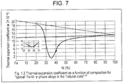
- The yoke of the sound-producing device according to the present invention is formed of an Fe-Ni alloy containing 32% by mass to 40% by mass of Ni. As shown in
Fig. 7 , Fe-Ni alloys containing Ni in amounts within this range have low linear expansion coefficients α. As shown inFig. 8 , a sound-producing device including this yoke exhibits an improvement in terms of nipple noise at high frequencies. - According to the present invention, even if an increased amount of heat is generated from the coil at high frequencies and increases the temperature of the yoke, which is housed in a narrow case, the change in yoke size can be reduced through the use of a yoke containing Ni in an amount within the above range. As a result, less variation occurs in the distance between the opposing magnets, and an increase in internal stress at the junctions between the yoke and the magnets and the junction between different parts of the yoke can be more easily prevented. The change in yoke size can also be reduced when the ambient temperature increases, and therefore, an increase in internal stress can be more easily prevented.
- Thus, the sound pressure level at high frequencies of 2 kHz or more can be stabilized.
-
-
Fig. 1 is a perspective view showing the external appearance of a sound-producing device according to an embodiment of the present invention. -
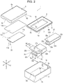
Fig. 2 is an exploded perspective view showing the sound-producing device according to the embodiment of the present invention. -
Fig. 3 is a sectional view, taken along line III-III, of the sound-producing device shown inFig. 1 . -
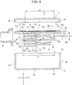
Fig. 4 is a sectional view showing the sound-producing device shown inFig. 3 in a disassembled state. -
Fig. 5 is a plan view of a frame of the sound-producing device according to the embodiment, with a vibrating plate, a first yoke, and an armature mounted thereon. -
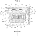
Fig. 6 is a sectional view, taken along line VI-VI, of the sound-producing device shown inFig. 3 . -
Fig. 7 is a graph showing the relationship between the Ni content and linear expansion coefficient of Fe-Ni alloys for forming yokes (source: PHISICS & APPLICATIONS OF PROPERTIES OF INVER ALLOYS, P4 (Maruzen Publishing Co., Ltd.)). -
Fig. 8(A) is a characteristic graph showing the relationship between frequency and SPL for the Example, andFig. 8(B) is a characteristic graph showing the relationship between frequency and SPL for the Comparative Example. - As shown in, for example,
Figs. 1 and2 , a sound-producing device 1 according to an embodiment of the present invention includes acase 2. Thecase 2 is composed of afirst case 3 and asecond case 4. Thefirst case 3 is a lower case, whereas thesecond case 4 is an upper case. Bothcases - As shown in
Fig. 2 , thefirst case 3 has abottom 3a, asidewall 3b enclosing the four sides thereof, and anopening edge 3c at the upper end of thesidewall 3b. Thesecond case 4 has aceiling 4a, asidewall 4b enclosing the four sides thereof, and anopening edge 4c at the lower end of the sidewall. Thefirst case 3 has a larger inner space than thesecond case 4, which functions as a lid for thefirst case 3. - As shown in
Figs. 3 and6 , aframe 5 is held between theopening edge 3c of thefirst case 3 and theopening edge 4c of thesecond case 4. As shown inFig. 2 , theframe 5 is formed from a nonmagnetic or magnetic metal plate with uniform thickness in the Z direction. Theframe 5 has an opening 5c formed through the center thereof from top to bottom. The opening 5c is a rectangular hole. - The
frame 5 has a vibrator-mounting surface 5b around the opening 5c in the upper surface thereof as shown in the figures. The vibrator-mountingsurface 5b is a frame-shaped flat surface. Theframe 5 has a heldportion 6 with reduced thickness that is integrally formed around the entire periphery of the vibrator-mountingsurface 5b. As shown inFigs. 3 ,4 , and6 , the upper surface of the heldportion 6 oriented in the same direction as the vibrator-mountingsurface 5b is an upper joiningcontact surface 6b. Astep 7 is formed between the vibrator-mountingsurface 5b and the upper joiningcontact surface 6b. - This
frame 5 is manufactured by press-forming a metal plate with uniform thickness. The opening 5c is formed by punching the metal plate. The heldportion 6 is formed by pressing the periphery of the vibrator-mountingsurface 5b so that its thickness in the Z direction is reduced. This pressing not only forms the heldportion 6, but also increases the rigidity of theframe 5. - The lower surface, as shown in the figures, around the
opening 5c in theframe 5 is a drive-mechanism mounting surface 5a, and the surface of the heldportion 6 facing downward as shown in the figures is a lower joiningcontact surface 6a. The drive-mechanism mounting surface 5a and the lower joiningcontact surface 6a are the same flat surface. Alternatively, there may be a step between the drive-mechanism mounting surface 5a and the lower joiningcontact surface 6a. - As shown in
Figs. 3 and4 , avibrator 10 is mounted on the vibrator-mountingsurface 5b of theframe 5, which faces upward as shown in the figures. Thevibrator 10 is composed of a vibratingplate 11 and avibration support sheet 12. The vibratingplate 11 is formed from a thin plate of a metal material such as aluminum or SUS304, optionally with a rib formed by press forming to enhance the bending strength. Although raised ribs are shown inFig. 6 , the ribs are omitted fromFig. 2 . Thevibration support sheet 12 is more flexible than the vibratingplate 11 and is formed from, for example, a sheet (film) of a resin such as polyethylene terephthalate (PET), nylon, or polyurethane. - The vibrating
plate 11 and thevibration support sheet 12 are rectangular. The area of the vibratingplate 11 is smaller than the opening area of theopening 5c in theframe 5, and the area of thevibration support sheet 12 is larger than the area of the vibratingplate 11. As shown inFig. 6 , the vibratingplate 11 is secured to the lower surface of thevibration support sheet 12 by bonding with an adhesive. Theouter periphery 12a of thevibration support sheet 12 is located outside the outer periphery of the vibratingplate 11. Thisouter periphery 12a is secured to the frame-shaped upper surface of theframe 5, i.e., the vibrator-mountingsurface 5b, with an adhesive therebetween. The bending and elasticity of thevibration support sheet 12 allow the vibratingplate 11 to vibrate while being fixed at afixed end 11c thereof such that afree end 11b thereof is displaced in the Z direction. Thefixed end 11c and thefree end 11b are shown inFigs. 2 ,3 , and4 . - As shown in
Figs. 3 and4 , a magnetic-field generating unit 20, acoil 27, and anarmature 32 are mounted on theframe 5. The magnetic-field generating unit 20 includes afirst yoke 21 and asecond yoke 22. The soft magnetic material forming thefirst yoke 21 and thesecond yoke 22 is a Ni-Fe alloy containing 32% by mass to 40% by mass of Ni. - As shown in
Fig. 2 , thesecond yoke 22 is bent into a U-shape and has a bottom 22a and a pair ofsides sides inner surface 21a of thefirst yoke 21, which has a flat shape. Thefirst yoke 21 and thesecond yoke 22 are secured together by a technique such as laser spot welding. When thefirst yoke 21 and thesecond yoke 22 are secured together, the inner surface of the bottom 22a of thesecond yoke 22 faces theinner surface 21a of thefirst yoke 21 so as to be parallel thereto. - As shown in
Figs. 2 ,4 , and6 , the magnetic-field generating unit 20 has afirst magnet 24 secured to theinner surface 21a of thefirst yoke 21 and asecond magnet 25 secured to the inner surface of the bottom 22a of thesecond yoke 22. Themagnets magnetized surface 24a of thefirst magnet 24 is of opposite polarity to amagnetized surface 25a of thesecond magnet 25. A gap δ is defined between themagnetized surface 24a of thefirst magnet 24 and themagnetized surface 25a of thesecond magnet 25 in the Z direction. - As shown in
Figs. 2 and3 , thecoil 27 is disposed beside the magnetic-field generating unit 20. Thecoil 27 is a covered conductor wound multiple turns about a winding axis extending in the Y direction. A windingend 27a of thecoil 27 oriented in the Y direction is secured to thefirst yoke 21 and thesecond yoke 22 by bonding. Alternatively, a support plate formed of a nonmagnetic material may be secured to the downward-facing outer surface of thefirst yoke 21, and the downward-facing outer winding portion of thecoil 27 may be bonded to the support plate. - As shown in
Figs. 2 ,3 , and4 , thearmature 32 is disposed in the sound-producing device 1. Thearmature 32 is formed from a plate of a magnetic material with uniform thickness, for example, a Ni-Fe alloy. Thearmature 32 is press-formed into a U-shape having amovable portion 32a, abase 32b, and abend 32c. As shown inFig. 2 , aleading end 32d of themovable portion 32a of thearmature 32 facing the free end side has a reduced width in the X direction and has acoupling hole 32e formed therethrough from top to bottom. - As shown in
Figs. 3 ,4 , and5 , thebase 32b of thearmature 32 is secured to an upward-facingouter surface 21b of thefirst yoke 21. Themovable portion 32a of thearmature 32 is inserted into the windingspace 27c of thecoil 27 and is also inserted into the gap δ between thefirst magnet 24 and thesecond magnet 25. Theleading end 32d of thearmature 32 protrudes out of the gap δ to the left as shown in the figures. - As shown in
Figs. 3 and4 , the upward-facingouter surface 21b of thefirst yoke 21 is joined and secured to the lower surface of theframe 5, i.e., the drive-mechanism mounting surface 5a. As shown inFigs. 5 and6 , thefirst yoke 21 is disposed so as to cross theopening 5c in theframe 5 in the X direction, and both ends of thefirst yoke 21 in the X direction are joined to the drive-mechanism mounting surface 5a of theframe 5. Thefirst yoke 21 and theframe 5 are secured together by laser spot welding. By securing together thefirst yoke 21 and theframe 5, the magnetic-field generating unit 20 is retained with respect to the drive-mechanism mounting surface 5a of theframe 5. - As shown in
Fig. 5 , thebase 32b of thearmature 32 is smaller than the opening area of theopening 5c in theframe 5. Thus, as shown inFig. 6 , when theouter surface 21b of thefirst yoke 21 is secured to the lower surface of theframe 5, i.e., the drive-mechanism mounting surface 5a, thebase 32b of thearmature 32, which is secured to theouter surface 21b, enters theopening 5c in theframe 5. The thickness of the base 32b in the Z direction is smaller than the thickness of theframe 5 in the Z direction. Thus, a gap is formed between the vibratingplate 11, which is also located in theopening 5c, and the base 32b of thearmature 32 in the Z direction so that the vibratingplate 11 can vibrate in the Z direction. - As shown in
Fig. 3 , thefree end 11b of the vibratingplate 11 is coupled to theleading end 32d of thearmature 32 by atransmitter 33. Thetransmitter 33 is a needle-shaped member formed of a metal or a synthetic resin, for example, an SUS202 pin. Anupper end 33a of thetransmitter 33 is inserted into a mountinghole 11e formed in the vibratingplate 11, and the vibratingplate 11 and thetransmitter 33 are secured together with an adhesive or solder. Alower end 33b of thetransmitter 33 is inserted into thecoupling hole 32e formed in theleading end 32d of thearmature 32, and thetransmitter 33 and theleading end 32d are secured together by laser spot welding or with an adhesive or solder. Thetransmitter 33 extends through theopening 5c in theframe 5 from top to bottom, and a portion of thetransmitter 33 is located in theopening 5c. - As shown in
Figs. 3 and6 , the heldportion 6 integrally formed around the periphery of theframe 5 is held and secured between the openingedge 3c of thefirst case 3 and the openingedge 4c of thesecond case 4. The openingedge 3c of thefirst case 3 abuts the lower surface of the heldportion 6, i.e., the lower joiningcontact surface 6a, whereas theopening edge 4c of thesecond case 4 abuts the upper surface of the heldportion 6, i.e., the upper joiningcontact surface 6b. Thefirst case 3 and thesecond case 4 are secured to the heldportion 6 by laser spot welding. Thus, the sound-producing device 1 shown inFig. 1 is finished. - The held
portion 6 is integrally formed around the entire periphery of theframe 5, and thestep 7 is formed between the vibrator-mountingsurface 5b and the upper surface of the heldportion 6, i.e., the upper joiningcontact surface 6b. Thus, the junction between the upper joiningcontact surface 6b and the openingedge 4c of thesecond case 4 is discontinuous with the vibrator-mountingsurface 5b at thestep 7. The presence of thestep 7 prevents the adhesive for bonding theouter periphery 12a of thevibration support sheet 12 to the vibrator-mountingsurface 5b from adhering to the junction between the upper joiningcontact surface 6b and the openingedge 4c. - When the
frame 5 is held and secured between thefirst case 3 and thesecond case 4, the vibratingplate 11 and thevibration support sheet 12 divide the inner space of thecase 2 into upper and lower spaces. The inner space of thesecond case 4 above the vibratingplate 11 and thevibration support sheet 12 is a sound-producing space. The sound-producing space leads to the outer space through asound outlet opening 4d formed in thesidewall 4b of thesecond case 4. - As shown in
Fig. 3 , asound outlet nozzle 41 leading to thesound outlet opening 4d is secured outside thecase 2. As shown inFigs. 2 and3 , an air inlet/outlet opening 3d is formed in the bottom of thefirst case 3, and the inner space of thefirst case 3 below the vibratingplate 11 and thevibration support sheet 12 leads to the outside atmosphere through the air inlet/outlet opening 3d. As shown inFig. 2 , a pair ofwire holes 3e are formed in thesidewall 3b of thefirst case 3. As shown inFig. 3 , a pair ofterminal portions 27b of the conductor forming thecoil 27 are routed outside through thewire holes 3e. Asubstrate 42 is secured outside thesidewall 3b of the case, and theterminal portions 27b pass through small holes formed in thesubstrate 42. By closing these small holes, thewire holes 3e are closed off from the outside. - The operation of the sound-producing device 1 will be described next.
- When a voice current is supplied to the
coil 27, a magnetic field induced by thecoil 27 and a magnetic field generated between themagnetized surface 24a of thefirst magnet 24 and themagnetized surface 25a of thesecond magnet 25 exert a vibrating force on themovable portion 32a of thearmature 32 in the Z direction. These vibrations are transmitted through thetransmitter 33 to the vibratingplate 11. The vibratingplate 11, which is supported by thevibration support sheet 12, vibrates while being fixed at thefixed end 11c thereof such that thefree end 11b thereof oscillates in the Z direction. These vibrations are transmitted to the vibratingplate 11, thus producing a sound pressure in the inner sound-producing space of thesecond case 4. This sound pressure is output from thesound outlet opening 4d to the outside. - The features of the sound-producing device 1 are as follows.
- The
first yoke 21 and the second yoke of the sound-producing device 1 according to the embodiment are formed of an Fe-Ni alloy containing 32% by mass to 40% by mass of Ni. A feature of this Fe-Ni alloy is that it has a low linear expansion coefficient α. - "Fe-Ni alloy" as used herein refers to an alloy based on iron (Fe) and nickel (Ni). It should be understood that this term also encompasses alloys containing other minor constituents. Typically, in addition to Fe and Ni, about 0.7% by mass of manganese (Mg) and less than 0.2% by mass of carbon (C) are present as minor constituents.
- As shown in
Fig. 7 , Fe-Ni alloys containing 32% by mass to 40% by mass of Ni have linear expansion coefficients α of 5 × 10⁻⁶ or less, which are significantly lower than that of, for example, PB permalloy, which contains about 45% by mass of Ni. - As shown in
Fig. 3 , the sound-producing device 1 has theyokes coil 27 within the sealed narrow space of thecase 2. Thus, for example, when a drive current with a high frequency of 2 kHz or more is supplied to thecoil 27, the coil generates an increased amount of heat, and this heat increases the temperature of theyokes - However, the
yokes first magnet 24 and thesecond magnet 25 varies only a little at elevated temperatures, so that unnecessary vibrations and resonance of thearmature 32 due to the variation in distance δ can be suppressed. Since the yokes deform only slightly, stress concentration at the junctions between themagnets yokes first yoke 21 and thesecond yoke 22 can be alleviated. Thus, the flow regularity of the magnetic flux generated by themagnets first yoke 21 to thearmature 32 is not impaired, and as shown inFig. 8(A) , the ripple noise level R1 of the sound pressure level at high frequencies of 2 kHz or more can be reduced. - Although the magnetic-
field generating unit 20 in the embodiment is composed of thefirst yoke 21 and the U-shapedsecond yoke 22, it is also possible to use a magnetic-field generating unit composed of a flat upper yoke, a flat lower yoke, and a pair of flat side yokes joined to the upper and lower yokes, that is, a total of four yokes. - A sound-producing device 1 serving as an Example included a
first yoke 21 and asecond yoke 22 that were formed of an Fe-Ni alloy containing 36% by mass of Ni. The plate thickness was 0.35 mmmm. A bulk of this alloy has a magnetic saturation of about 1.2 T. The width W1 of theyokes Fig. 2 in the Y direction was 1.6 mm, the width W2 of thesecond yoke 22 in the X direction was 2.7 mm, and the height H of the magnetic-field generating unit 20 in the Z direction was 1.8 mm. - The
first magnet 24 and the second magnet were AlNiCo magnets. - The number of turns of the
coil 27 was 200 turns. - The
armature 32 was formed of PB permalloy, i.e., an Fe-Ni alloy containing 45% by mass of Ni, and had a plate thickness of 0.15 mm. - The vibrating
plate 11 was formed of aluminum and had a plate thickness of 0.05 mm. - The
armature 32 was formed of PB permalloy, i.e., an Fe-Ni alloy containing 45% by mass of Ni. A bulk of PB permalloy has a magnetic saturation of about 1.5 T. The size of thearmature 32 and the structures of the magnetic-field generating unit 20 and thecoil 27 were identical to those of the Example. - SPL was measured with a model S265-2A sound analyzer (available from Etani Electronics Co., Ltd.). A coupler compliant to IEC 60318-4 was used.
- The sound pressure level was measured with a power of 1 mW at 1 kHz (constant applied voltage) in the range from 10 Hz to 100 kHz.
-
Fig. 8(A) shows the SPL measurement results for the Example, whereasFig. 8(B) shows the SPL measurement results for the Comparative Example. Whereas the sound pressure levels inFigs. 8(A) and 8(B) were similar over a wide range of frequencies of 2 kHz or more, the ripple noise level R1 of the Example inFig. 8(A) was nearly half the ripple noise level R2 of the Comparative Example inFig. 8(B) . -
- 1
- sound-producing device
- 2
- case
- 3
- first case
- 4
- second case
- 4d
- sound outlet opening
- 5
- frame
- 5a
- drive-mechanism mounting surface
- 5b
- vibrator-mounting surface
- 10
- vibrator
- 11
- vibrating plate
- 11b
- free end
- 11c
- fixed end
- 12
- vibration support sheet
- 21
- first yoke
- 22
- second yoke
- 24
- first magnet
- 25
- second magnet
- 27
- coil
- 27a
- winding end
- 32
- armature
- 32a
- movable portion
- 32b
- base
- 32c
- bend
- 33
- transmitter
Claims (5)
- A sound-producing device comprising, in a case, a yoke comprising a magnetic material, a magnet supported by the yoke, a coil, an armature extending through the coil and facing the magnet, and a vibrator configured to vibrate in response to operation of the armature,
wherein the yoke comprises an Fe-Ni alloy containing 32% by mass to 40% by mass of Ni. - The sound-producing device according to Claim 1,
wherein the Fe-Ni alloy contains 36% by mass of Ni. - The sound-producing device according to Claim 1 or 2, wherein the magnet is secured to each of opposing inner surfaces of the yoke, the armature being located between the opposing magnets.
- The sound-producing device according to Claim 3,
wherein a frame is disposed in the case, the vibrator being supported on one side of the frame, the yoke being secured to another side of the frame. - The sound-producing device according to Claim 4,
wherein the case comprises first and second cases combined together, the frame being held and secured between the first and second cases.
Applications Claiming Priority (2)
| Application Number | Priority Date | Filing Date | Title |
|---|---|---|---|
| JP2016159667 | 2016-08-16 | ||
| PCT/JP2017/008268 WO2018034016A1 (en) | 2016-08-16 | 2017-03-02 | Sound generation device |
Publications (2)
| Publication Number | Publication Date |
|---|---|
| EP3503586A1 true EP3503586A1 (en) | 2019-06-26 |
| EP3503586A4 EP3503586A4 (en) | 2020-01-01 |
Family
ID=61196543
Family Applications (1)
| Application Number | Title | Priority Date | Filing Date |
|---|---|---|---|
| EP17841244.1A Withdrawn EP3503586A4 (en) | 2016-08-16 | 2017-03-02 | Sound generation device |
Country Status (5)
| Country | Link |
|---|---|
| US (1) | US20190182602A1 (en) |
| EP (1) | EP3503586A4 (en) |
| JP (1) | JP6697145B2 (en) |
| CN (1) | CN109716790A (en) |
| WO (1) | WO2018034016A1 (en) |
Families Citing this family (1)
| Publication number | Priority date | Publication date | Assignee | Title |
|---|---|---|---|---|
| US11659337B1 (en) * | 2021-12-29 | 2023-05-23 | Knowles Electronics, Llc | Balanced armature receiver having improved shock performance |
Family Cites Families (12)
| Publication number | Priority date | Publication date | Assignee | Title |
|---|---|---|---|---|
| US3617653A (en) * | 1967-05-16 | 1971-11-02 | Tibbetts Industries | Magnetic reed type acoustic transducer with improved armature |
| JPS5023613B1 (en) * | 1970-04-23 | 1975-08-08 | ||
| US4272654A (en) * | 1979-01-08 | 1981-06-09 | Industrial Research Products, Inc. | Acoustic transducer of improved construction |
| JPH03277746A (en) * | 1990-03-28 | 1991-12-09 | Nisshin Steel Co Ltd | Soft magnetic alloy showing good magnetic property by vacuum magnetic annealing |
| JPH11233342A (en) * | 1998-02-10 | 1999-08-27 | Daido Denshi:Kk | Method for removing magnetic powder and removing device used for the same |
| CN1162565C (en) * | 2001-03-30 | 2004-08-18 | 日矿金属株式会社 | Alloy thin strip and its manufacturing method |
| JP2002300698A (en) * | 2001-04-02 | 2002-10-11 | Star Micronics Co Ltd | Receivers and portable communication devices |
| JP5342474B2 (en) * | 2010-02-25 | 2013-11-13 | 日本航空電子工業株式会社 | precision equipment |
| JP5447216B2 (en) * | 2010-06-17 | 2014-03-19 | ソニー株式会社 | Acoustic transducer and method for assembling acoustic transducer |
| JP5811705B2 (en) * | 2011-09-05 | 2015-11-11 | ソニー株式会社 | Earphone device |
| CN103024645B (en) * | 2011-09-27 | 2017-02-08 | 苏州新吴光电科技有限公司 | Magnetic yoke device for moving-iron type microphone/transducer |
| JP5802547B2 (en) * | 2011-12-28 | 2015-10-28 | リオン株式会社 | Electromechanical transducer, electroacoustic transducer and hearing aid using the same |
-
2017
- 2017-03-02 CN CN201780049631.4A patent/CN109716790A/en active Pending
- 2017-03-02 WO PCT/JP2017/008268 patent/WO2018034016A1/en not_active Ceased
- 2017-03-02 EP EP17841244.1A patent/EP3503586A4/en not_active Withdrawn
- 2017-03-02 JP JP2018534263A patent/JP6697145B2/en not_active Expired - Fee Related
-
2019
- 2019-02-15 US US16/276,928 patent/US20190182602A1/en not_active Abandoned
Also Published As
| Publication number | Publication date |
|---|---|
| WO2018034016A1 (en) | 2018-02-22 |
| US20190182602A1 (en) | 2019-06-13 |
| JPWO2018034016A1 (en) | 2019-06-20 |
| JP6697145B2 (en) | 2020-05-20 |
| EP3503586A4 (en) | 2020-01-01 |
| CN109716790A (en) | 2019-05-03 |
Similar Documents
| Publication | Publication Date | Title |
|---|---|---|
| US10610893B2 (en) | Vibration actuator and portable device | |
| US8995705B2 (en) | Multi-layer armature for moving armature receiver | |
| US10610892B2 (en) | Vibration actuator and portable device | |
| US10610894B2 (en) | Vibration actuator and portable device | |
| EP0650308A1 (en) | Electroacoustic transducer and method of fabricating the same | |
| JP5802547B2 (en) | Electromechanical transducer, electroacoustic transducer and hearing aid using the same | |
| US20190182602A1 (en) | Sound-producing device | |
| JP3251868B2 (en) | Electromagnetic acoustic transducer | |
| JP4091006B2 (en) | Electroacoustic transducer | |
| EP3352478B1 (en) | Sound production device | |
| JP2006186615A (en) | Electric vibration transducer | |
| JP6014787B1 (en) | Sound generator | |
| JPH08203751A (en) | Coil component for electric equipment | |
| EP1215935B1 (en) | Electroacoustic transducer | |
| US20200021917A1 (en) | Speaker | |
| JP2019092113A (en) | Sound producing device | |
| US20190313191A1 (en) | Sound producing device | |
| CN111921827B (en) | Vibration generating device | |
| JP3662190B2 (en) | Electroacoustic transducer | |
| JP2002078087A (en) | Electromagnetic sound transducer | |
| JP4644961B2 (en) | Inductance element | |
| JP3639784B2 (en) | Electroacoustic transducer | |
| CN209517504U (en) | Sounding device | |
| JP2002149162A (en) | Electromagnetic sound transducer | |
| JP3732088B2 (en) | Electroacoustic transducer |
Legal Events
| Date | Code | Title | Description |
|---|---|---|---|
| STAA | Information on the status of an ep patent application or granted ep patent |
Free format text: STATUS: THE INTERNATIONAL PUBLICATION HAS BEEN MADE |
|
| PUAI | Public reference made under article 153(3) epc to a published international application that has entered the european phase |
Free format text: ORIGINAL CODE: 0009012 |
|
| STAA | Information on the status of an ep patent application or granted ep patent |
Free format text: STATUS: REQUEST FOR EXAMINATION WAS MADE |
|
| 17P | Request for examination filed |
Effective date: 20190205 |
|
| AK | Designated contracting states |
Kind code of ref document: A1 Designated state(s): AL AT BE BG CH CY CZ DE DK EE ES FI FR GB GR HR HU IE IS IT LI LT LU LV MC MK MT NL NO PL PT RO RS SE SI SK SM TR |
|
| AX | Request for extension of the european patent |
Extension state: BA ME |
|
| DAV | Request for validation of the european patent (deleted) | ||
| DAX | Request for extension of the european patent (deleted) | ||
| A4 | Supplementary search report drawn up and despatched |
Effective date: 20191202 |
|
| RIC1 | Information provided on ipc code assigned before grant |
Ipc: H04R 11/02 20060101AFI20191126BHEP |
|
| GRAP | Despatch of communication of intention to grant a patent |
Free format text: ORIGINAL CODE: EPIDOSNIGR1 |
|
| STAA | Information on the status of an ep patent application or granted ep patent |
Free format text: STATUS: GRANT OF PATENT IS INTENDED |
|
| INTG | Intention to grant announced |
Effective date: 20200723 |
|
| STAA | Information on the status of an ep patent application or granted ep patent |
Free format text: STATUS: THE APPLICATION IS DEEMED TO BE WITHDRAWN |
|
| 18D | Application deemed to be withdrawn |
Effective date: 20201203 |