EP3503410A1 - Common decoding processor for ldpc codes with multiple lengths - Google Patents
Common decoding processor for ldpc codes with multiple lengths Download PDFInfo
- Publication number
- EP3503410A1 EP3503410A1 EP19157328.6A EP19157328A EP3503410A1 EP 3503410 A1 EP3503410 A1 EP 3503410A1 EP 19157328 A EP19157328 A EP 19157328A EP 3503410 A1 EP3503410 A1 EP 3503410A1
- Authority
- EP
- European Patent Office
- Prior art keywords
- code block
- code
- data
- bits
- parallel processing
- Prior art date
- Legal status (The legal status is an assumption and is not a legal conclusion. Google has not performed a legal analysis and makes no representation as to the accuracy of the status listed.)
- Ceased
Links
- 238000000034 method Methods 0.000 claims abstract description 49
- 238000012545 processing Methods 0.000 claims description 43
- 238000004891 communication Methods 0.000 claims description 14
- 230000005540 biological transmission Effects 0.000 description 39
- 230000008569 process Effects 0.000 description 15
- 239000011159 matrix material Substances 0.000 description 13
- 238000013461 design Methods 0.000 description 11
- 238000004904 shortening Methods 0.000 description 8
- 230000008901 benefit Effects 0.000 description 5
- 238000005265 energy consumption Methods 0.000 description 4
- 238000012804 iterative process Methods 0.000 description 4
- 238000013459 approach Methods 0.000 description 2
- 230000001419 dependent effect Effects 0.000 description 2
- 238000012986 modification Methods 0.000 description 2
- 230000004048 modification Effects 0.000 description 2
- 238000005457 optimization Methods 0.000 description 2
- 230000009897 systematic effect Effects 0.000 description 2
- 230000008859 change Effects 0.000 description 1
- 230000008030 elimination Effects 0.000 description 1
- 238000003379 elimination reaction Methods 0.000 description 1
- 230000006872 improvement Effects 0.000 description 1
- 230000009467 reduction Effects 0.000 description 1
- 238000012546 transfer Methods 0.000 description 1
- 239000002699 waste material Substances 0.000 description 1
Images


Classifications
-
- H—ELECTRICITY
- H03—ELECTRONIC CIRCUITRY
- H03M—CODING; DECODING; CODE CONVERSION IN GENERAL
- H03M13/00—Coding, decoding or code conversion, for error detection or error correction; Coding theory basic assumptions; Coding bounds; Error probability evaluation methods; Channel models; Simulation or testing of codes
- H03M13/63—Joint error correction and other techniques
- H03M13/635—Error control coding in combination with rate matching
- H03M13/6362—Error control coding in combination with rate matching by puncturing
- H03M13/6368—Error control coding in combination with rate matching by puncturing using rate compatible puncturing or complementary puncturing
- H03M13/6393—Rate compatible low-density parity check [LDPC] codes
-
- H—ELECTRICITY
- H03—ELECTRONIC CIRCUITRY
- H03M—CODING; DECODING; CODE CONVERSION IN GENERAL
- H03M13/00—Coding, decoding or code conversion, for error detection or error correction; Coding theory basic assumptions; Coding bounds; Error probability evaluation methods; Channel models; Simulation or testing of codes
- H03M13/03—Error detection or forward error correction by redundancy in data representation, i.e. code words containing more digits than the source words
- H03M13/05—Error detection or forward error correction by redundancy in data representation, i.e. code words containing more digits than the source words using block codes, i.e. a predetermined number of check bits joined to a predetermined number of information bits
- H03M13/11—Error detection or forward error correction by redundancy in data representation, i.e. code words containing more digits than the source words using block codes, i.e. a predetermined number of check bits joined to a predetermined number of information bits using multiple parity bits
- H03M13/1102—Codes on graphs and decoding on graphs, e.g. low-density parity check [LDPC] codes
- H03M13/1105—Decoding
-
- H—ELECTRICITY
- H03—ELECTRONIC CIRCUITRY
- H03M—CODING; DECODING; CODE CONVERSION IN GENERAL
- H03M13/00—Coding, decoding or code conversion, for error detection or error correction; Coding theory basic assumptions; Coding bounds; Error probability evaluation methods; Channel models; Simulation or testing of codes
- H03M13/03—Error detection or forward error correction by redundancy in data representation, i.e. code words containing more digits than the source words
- H03M13/05—Error detection or forward error correction by redundancy in data representation, i.e. code words containing more digits than the source words using block codes, i.e. a predetermined number of check bits joined to a predetermined number of information bits
- H03M13/11—Error detection or forward error correction by redundancy in data representation, i.e. code words containing more digits than the source words using block codes, i.e. a predetermined number of check bits joined to a predetermined number of information bits using multiple parity bits
- H03M13/1102—Codes on graphs and decoding on graphs, e.g. low-density parity check [LDPC] codes
-
- H—ELECTRICITY
- H03—ELECTRONIC CIRCUITRY
- H03M—CODING; DECODING; CODE CONVERSION IN GENERAL
- H03M13/00—Coding, decoding or code conversion, for error detection or error correction; Coding theory basic assumptions; Coding bounds; Error probability evaluation methods; Channel models; Simulation or testing of codes
- H03M13/03—Error detection or forward error correction by redundancy in data representation, i.e. code words containing more digits than the source words
- H03M13/05—Error detection or forward error correction by redundancy in data representation, i.e. code words containing more digits than the source words using block codes, i.e. a predetermined number of check bits joined to a predetermined number of information bits
- H03M13/11—Error detection or forward error correction by redundancy in data representation, i.e. code words containing more digits than the source words using block codes, i.e. a predetermined number of check bits joined to a predetermined number of information bits using multiple parity bits
- H03M13/1102—Codes on graphs and decoding on graphs, e.g. low-density parity check [LDPC] codes
- H03M13/1105—Decoding
- H03M13/1131—Scheduling of bit node or check node processing
- H03M13/1137—Partly parallel processing, i.e. sub-blocks or sub-groups of nodes being processed in parallel
-
- H—ELECTRICITY
- H03—ELECTRONIC CIRCUITRY
- H03M—CODING; DECODING; CODE CONVERSION IN GENERAL
- H03M13/00—Coding, decoding or code conversion, for error detection or error correction; Coding theory basic assumptions; Coding bounds; Error probability evaluation methods; Channel models; Simulation or testing of codes
- H03M13/03—Error detection or forward error correction by redundancy in data representation, i.e. code words containing more digits than the source words
- H03M13/05—Error detection or forward error correction by redundancy in data representation, i.e. code words containing more digits than the source words using block codes, i.e. a predetermined number of check bits joined to a predetermined number of information bits
- H03M13/11—Error detection or forward error correction by redundancy in data representation, i.e. code words containing more digits than the source words using block codes, i.e. a predetermined number of check bits joined to a predetermined number of information bits using multiple parity bits
- H03M13/1102—Codes on graphs and decoding on graphs, e.g. low-density parity check [LDPC] codes
- H03M13/1148—Structural properties of the code parity-check or generator matrix
- H03M13/116—Quasi-cyclic LDPC [QC-LDPC] codes, i.e. the parity-check matrix being composed of permutation or circulant sub-matrices
-
- H—ELECTRICITY
- H03—ELECTRONIC CIRCUITRY
- H03M—CODING; DECODING; CODE CONVERSION IN GENERAL
- H03M13/00—Coding, decoding or code conversion, for error detection or error correction; Coding theory basic assumptions; Coding bounds; Error probability evaluation methods; Channel models; Simulation or testing of codes
- H03M13/25—Error detection or forward error correction by signal space coding, i.e. adding redundancy in the signal constellation, e.g. Trellis Coded Modulation [TCM]
- H03M13/255—Error detection or forward error correction by signal space coding, i.e. adding redundancy in the signal constellation, e.g. Trellis Coded Modulation [TCM] with Low Density Parity Check [LDPC] codes
-
- H—ELECTRICITY
- H03—ELECTRONIC CIRCUITRY
- H03M—CODING; DECODING; CODE CONVERSION IN GENERAL
- H03M13/00—Coding, decoding or code conversion, for error detection or error correction; Coding theory basic assumptions; Coding bounds; Error probability evaluation methods; Channel models; Simulation or testing of codes
- H03M13/61—Aspects and characteristics of methods and arrangements for error correction or error detection, not provided for otherwise
- H03M13/618—Shortening and extension of codes
-
- H—ELECTRICITY
- H03—ELECTRONIC CIRCUITRY
- H03M—CODING; DECODING; CODE CONVERSION IN GENERAL
- H03M13/00—Coding, decoding or code conversion, for error detection or error correction; Coding theory basic assumptions; Coding bounds; Error probability evaluation methods; Channel models; Simulation or testing of codes
- H03M13/63—Joint error correction and other techniques
- H03M13/635—Error control coding in combination with rate matching
- H03M13/6356—Error control coding in combination with rate matching by repetition or insertion of dummy data, i.e. rate reduction
-
- H—ELECTRICITY
- H03—ELECTRONIC CIRCUITRY
- H03M—CODING; DECODING; CODE CONVERSION IN GENERAL
- H03M13/00—Coding, decoding or code conversion, for error detection or error correction; Coding theory basic assumptions; Coding bounds; Error probability evaluation methods; Channel models; Simulation or testing of codes
- H03M13/63—Joint error correction and other techniques
- H03M13/635—Error control coding in combination with rate matching
- H03M13/6362—Error control coding in combination with rate matching by puncturing
-
- H—ELECTRICITY
- H03—ELECTRONIC CIRCUITRY
- H03M—CODING; DECODING; CODE CONVERSION IN GENERAL
- H03M13/00—Coding, decoding or code conversion, for error detection or error correction; Coding theory basic assumptions; Coding bounds; Error probability evaluation methods; Channel models; Simulation or testing of codes
- H03M13/65—Purpose and implementation aspects
- H03M13/6508—Flexibility, adaptability, parametrability and configurability of the implementation
- H03M13/6516—Support of multiple code parameters, e.g. generalized Reed-Solomon decoder for a variety of generator polynomials or Galois fields
-
- H—ELECTRICITY
- H04—ELECTRIC COMMUNICATION TECHNIQUE
- H04L—TRANSMISSION OF DIGITAL INFORMATION, e.g. TELEGRAPHIC COMMUNICATION
- H04L1/00—Arrangements for detecting or preventing errors in the information received
- H04L1/004—Arrangements for detecting or preventing errors in the information received by using forward error control
- H04L1/0056—Systems characterized by the type of code used
- H04L1/0057—Block codes
-
- H—ELECTRICITY
- H04—ELECTRIC COMMUNICATION TECHNIQUE
- H04L—TRANSMISSION OF DIGITAL INFORMATION, e.g. TELEGRAPHIC COMMUNICATION
- H04L1/00—Arrangements for detecting or preventing errors in the information received
- H04L1/004—Arrangements for detecting or preventing errors in the information received by using forward error control
- H04L1/0056—Systems characterized by the type of code used
- H04L1/0067—Rate matching
- H04L1/0068—Rate matching by puncturing
-
- H—ELECTRICITY
- H03—ELECTRONIC CIRCUITRY
- H03M—CODING; DECODING; CODE CONVERSION IN GENERAL
- H03M13/00—Coding, decoding or code conversion, for error detection or error correction; Coding theory basic assumptions; Coding bounds; Error probability evaluation methods; Channel models; Simulation or testing of codes
- H03M13/03—Error detection or forward error correction by redundancy in data representation, i.e. code words containing more digits than the source words
- H03M13/05—Error detection or forward error correction by redundancy in data representation, i.e. code words containing more digits than the source words using block codes, i.e. a predetermined number of check bits joined to a predetermined number of information bits
- H03M13/11—Error detection or forward error correction by redundancy in data representation, i.e. code words containing more digits than the source words using block codes, i.e. a predetermined number of check bits joined to a predetermined number of information bits using multiple parity bits
- H03M13/1102—Codes on graphs and decoding on graphs, e.g. low-density parity check [LDPC] codes
- H03M13/1148—Structural properties of the code parity-check or generator matrix
- H03M13/116—Quasi-cyclic LDPC [QC-LDPC] codes, i.e. the parity-check matrix being composed of permutation or circulant sub-matrices
- H03M13/1165—QC-LDPC codes as defined for the digital video broadcasting [DVB] specifications, e.g. DVB-Satellite [DVB-S2]
Definitions
- LDPC codes are a form of linear error correcting code, which are used to transmit messages over a noisy transmission channel.
- a transmitter uses an LDPC code to encode data, it encodes it in a redundant form. This redundancy allows the receiver to detect a limited number of errors that may occur anywhere in the message, and also allows the receiver to correct these errors without retransmission of data.
- LDPC codes are powerful block codes whose performances get close to Shannon capacity as their block size increases.
- efficient and high performing LDPC codes have been standardized by several standardization bodies, the first being DVB-S2.
- DVB-S2 two different coded block sizes have been used: 64800 and 16200 bits.
- LPDC codes are finding increasing use in applications where reliable and highly efficient information transfer over bandwidth in the presence of data-corrupting noise. LPDC codes are currently utilized in digital video broadcasting, microwave communications, cell phone communications, and Wi-Fi.
- FIG. 1 illustrates an example system 100.
- system 100 includes a gateway 102, a user terminal 104, a user terminal 106, a user terminal 108, a user terminal 110, a user terminal 112, and the internet 114.
- User terminal 104 is arranged to send code blocks, which are 120 bits in length, to gateway 102 along bi-directional transmission line 116.
- User terminal 106 is arranged to send code blocks, which are 240 bits in length, to gateway 102 along bi-directional transmission line 118.
- User terminal 108 is arranged to send code blocks, which are 360 bits in length, to gateway 102 along bi-directional transmission line 120.
- User terminal 110 is arranged to send code blocks, which are 480 bits in length, to gateway 102 along bi-directional transmission line 122.
- User terminal 112 is arranged to send code blocks, which are 600 bits in length, to gateway 102 along bi-directional transmission line 124.
- each user terminal is transmitting discrete code blocks of a certain length.
- each user terminal is operable to transmit a plurality of code block lengths, which are dependent on the amount of information to be transmitted.
- Gateway 102 is arranged to send and receive data from, bi-directional transmission line 116 from user terminal 104, bi-directional transmission line 118 from user terminal 106, bi-directional transmission line 120 from user terminal 108, bi-directional transmission line 122 from user terminal 110, and bi-directional transmission line 124 from user terminal 112.
- Gateway 102 is additionally arranged to send encoded data stream 126 to internet 114.
- Gateway 102 contains a LDPC code and architecture for each respective code block length that it supports.
- gateway 102 contains an LDPC code and architecture set for each of the code block it supports, the lengths of which are 120 bits, 240 bits, 360 bits, 480 bits, and 600 bits.
- a user will send code blocks to gateway 102 from a user terminal.
- Each individual user terminal encodes the data with an LDPC encoder and then sends the encoded data blocks to gateway 102.
- gateway 102 When gateway 102 receives the encoded LDPC code blocks, it decodes them using an LDPC decoder to obtain the originally transmitted data. Note that when gateway 102 wants to send data to a user terminal the process is reversed.
- gateway 102 When gateway 102 wants to send data to a user terminal, it uses an LDPC encoder to encode the data. Once the data is encoded, the encoded code blocks are transmitted to a user terminal, which then decodes the code blocks to obtain the originally transmitted data. Once the data is encoded, it may be sent to internet 112 via internet connection 126.
- TCP transmission control protocol
- Each data packet that is sent has a sequence number that is used to reconstruct the transmitted data in the correct order.
- the reliability of each packet i.e. robustness against the channel noise
- FIG. 2 illustrates an example of various data stream lengths as well as supported data stream lengths of system 200.
- system 200 includes data stream sizes that are integer multiples of 120 bits.
- Data stream 202, data stream 206, data stream 212, data stream 222, and data stream 230 represent the data stream lengths that are supported by the system hardware.
- Data stream 202 through data stream 230 represents all possible incoming data stream lengths. Note that it is possible of for an incoming data stream to exceed the possible supported data stream size but for the purposes of discussion there is a cut off at 1800 bits represented by data stream 230.
- FIG. 3A and FIG. 3B illustrates the transmission of a data stream size that is not supported by the receiver hardware.
- system 300 includes supported data stream 222, data stream length 224, a data packet 326 and a data packet 328.
- Supported data stream length 222 is the length of 11 data packets, each of which is 120 bits in length.
- Data stream 224 is comprised of 12 individual data packets, data packet 302 through data packet 324, each of which is 120 bits in length.
- Data packet 326 is a packet that can hold 11 data packets each of which are 120 bits in length.
- Data packet 328 is a packet that can hold 11 data packets each of which are 120 bits in length.
- data stream 224 needs to be converted into a data stream, of two or more pieces, with lengths that can be put into data packets that are supported by the receiver hardware. Since data stream 224 is too long to fit into data packet 322, it needs to be divided up into smaller lengths that will fit into a supported data packet size that will then be transmitted.
- FIG. 3B illustrates an example data stream that has been divided into smaller stream lengths that can fit into data packets which are supported by the receiver hardware.
- data stream 224 has been divided into two lengths, which are small enough to fit into supported data packet 326 and data packet 328, both of which are the same length as supported data packet 222.
- Data packet 326 is filled with data packet 302 through data packet 322 from data stream 224 leaving data packet 324 left over.
- Data packet 328 contains data packet 324 from data stream 224 but is otherwise empty. Since a data packet can't be sent unless it is full, the open space is filled with dummy bits. Dummy bits do not affect the content of data packet 328; they are simply placed in data packet 328 to fill it so it may be transmitted.
- data stream 224 has been divided into two smaller lengths that have been put into data packet 326 and data packet 328, and they are ready to be transmitted to the receiver.
- FIG. 4A and FIG. 4B illustrate the transmission of a data stream length that is not supported by receiver hardware.
- system 400 includes supported data stream length 206, data stream 224, a data packet 402, a data packet 404, a data packet 406, and a data packet 408.
- Supported data stream length 206 is the length of 3 data packets, each of which is 120 bits in length.
- Data stream 224 is comprised of 12 individual data packets, data packet 302 through data packet 324, each of which is 120 bits in length.
- Data packet 402, data packet 404, data packet 406, and data packet 408 can each hold 3 packets of data, each of which are 120 bits in length.
- data stream 224 needs to be converted into a data stream lengths that can be put into packet sizes that are supported by the receiver hardware. Since data stream 224 is too long to fit into data packet 402, it needs to be divided up into smaller lengths that will fit into a supported data packet size that will then be transmitted.
- FIG. 4B illustrates an example data stream that has been divided into smaller stream lengths which are able to fit into data packet which are supported by the receiver hardware.
- data stream 224 has been divided into 4 equal lengths, each of which are small enough to fit into data packet 402, data packet 404, data packet 406, or data packet 408. Each data packet is filled with information from data stream 224.
- data packet 402 data packet 404, data packet 406, and data packet 408 are filled with information from data stream 224, they are ready to be transmitted to the receiver.
- the first problem is that of large block size support as shown in FIGs. 3A-4B .
- a code block may sometimes need to be very small and sometimes very large.
- Another problem with the current methods of utilizing LDPC codes is the lack of intermediate block size support as shown in FIG. 1 . If one wants to support many different code block lengths that it may be undesirable to design a separate LDPC code for each block length.
- the final problem with the current methods for utilizing LDPC codes as shown in FIG. 1 is the space that is taken up by the architecture used for each LDPC code. If one wants to support many different code block lengths, an LDPC code and its respective architecture needs to be implemented in the hardware design for each individual code block length.
- the transmitted block sizes need to be chosen so that the minimum transmitted size is maximized. This means that when a user wants to transmit more data than the maximum supported block size, the transmitted block sizes should be as large as possible without having empty space in the transmitted block.
- What is needed is a system and method to address the problem of intermediate block size support.
- bits in the code should be shortened, punctured, and repeated to derive intermediate code block lengths.
- the location of punctured bits should be carefully chosen in order not to cause substantial performance loss.
- What is needed is a system and method for using common decoder architecture for different code rates and block sizes. It may also be desirable to use the same piece of hardware to decode all block sizes and all code rates with the help of a code-specific set of parameters. This will reduce the complexity of the receiver where a different decoder is used for different codes.
- the present invention provides a system and method for supporting large block sizes. By choosing to transmit incoming data blocks such that, the minimum transmitted size is maximized, one can transmit blocks reliably and efficiently despite the original code block being too large to be supported.
- the present invention additionally provides a system and method for supporting intermediate block sizes. Through puncturing, shortening, and repeating incoming code blocks as indicated by a parity check matrix it is possible to create code blocks of an intermediate length.
- the present invention additionally provides a system and method for using common decoder architecture for different code rates and block sizes.
- a hardware architecture that is common to all code blocks it is possible to support many different codes by running them through an iterative process utilizing the architecture common to all code blocks.
- a method for supporting code blocks of any length and converting them into code blocks that are large or intermediate in length, which are compatible with a system's hardware.
- a method is also provided for using a common decoder architecture for processing all incoming code blocks.
- an encoder is provided to encode a string of information bits having a bit length k into a string of encoded bits having a bit length N.
- the encoder includes a plurality of LDPC portions and a controller.
- Each of the LDPC portions can encode a portion of the information bits into a LDPC code block, respectively, wherein each of the respective LDPC code blocks has a different bit length.
- the controller can instruct a number of the LDPC portions to encode the information bits into a plurality of LDPC code blocks such that the minimum encoded block size is maximized.
- an encoder to encode a string of information bits having a bit length k into a string of encoded bits having a bit length N.
- the encoder includes a LDPC portion and a controller.
- the LDPC portion can encode information bits into LDPC code blocks, wherein each of the LDPC code blocks has a bit length S 1 .
- the LDPC portion can do at least one of pad, shorten, puncture or repeat a bit within one of the string of information bits and parity bits associated with the string of information bits to create an encoded LDPC code block having a length N.
- a decoder for use with a first LDPC code block and a second LDPC code block.
- the first low LDPC block has a first bit length
- the second LDPC block has a second bit length, wherein the first bit length is shorter than the second bit length.
- the decoder includes a receiving portion, a memory portion an address table portion, a processing engine and a controller.
- the receiving portion can receive a code block.
- the memory portion can store the first low density parity check code block as a first data structure and can store the second low density parity check code block as a second data structure.
- the address table portion has a first address table stored therein and has a second address table stored therein.
- the first address table relates a structure of the first LDPC code block to the first data structure
- the second address table relates a structure of the second LDPC code block to the second data structure.
- the processing engine can process blocks of data having a third bit length, wherein the third bit length is shorter than the first bit length.
- the controller can instruct the memory portion to store the first LDPC code block as the first data structure and can instruct the processing engine to process the blocks of data within the stored first LDPC code block based on the first address table.
- the controller can to instruct the memory portion to store the second LDPC code block as the second data structure and can instruct the processing engine to process the blocks of data within the stored second LDPC code block based on the second address table.
- aspects of the present invention provide a method for supporting large code block lengths.
- code blocks that are larger than the supported code block length available are broken up into small pieces in such a way that the minimum transmitted size is maximized.
- code blocks are now broken up into the largest possible size that can be transmitted without having wasted space.
- aspects of the present invention provide a method for supporting intermediate code block lengths.
- Practical LDPC codes of interest have structured parity check matrices, therefore their storage is relatively much easier than random parity check matrices.
- the number of desired parity check matrices may be so large that designing a separate LDPC codes for each block size may be undesirable.
- the general rule provided in accordance with aspects of the present invention, states that for lower code rates such as 1/2, 2/3 and 4/5 punctured bits should be chosen among the parity bits, whereas for high code rates such as 8/9 and 9/10, punctured bits should be chosen among the systematic bits to minimize the performance loss.
- aspects of the present invention provide a method for using common decoder architecture for different code rates and block sizes.
- the current method for supporting many different code block lengths adds an undesired amount of complexity to a system.
- the present invention provides a method for finding a common decoder architecture, and then using the architecture to support all the code blocks.
- a fully parallel LDPC decoder implementation would have as many bit nodes as the number of coded bits and as many check nodes as the number of parity check equations. While this implementation would have very high speeds, it would be extremely complex. Moreover it may need to have as many instantiations of the decoder as the number of parity check matrices that would be implemented.
- a more practical approach may be to implement a partially parallel decoder where a certain number M of physical parallel engines would process M logical nodes of the LDPC codes at a time.
- This approach not only simplifies the decoder significantly, but also allows to support all of the different parity check matrices using a common decoder hardware, provided the same inherent structure is kept among all of the codes. Only a code specific table would change whenever a new parity check matrix is deployed. This table would tell the decoder parallel engines where to access the relevant edges for the logical nodes being processed.
- the number of parallel engines M influence the decoder speed and complexity, and it is determined by the code design.
- M for different parity check matrices should be as close to one another as possible.
- an encoder to encode a string of information bits having a bit length k into a string of encoded bits having a bit length N.
- the encoder includes a plurality of LDPC portions. Each LDPC portion can encode a portion of the information bits into a LDPC code block, respectively, wherein each of the respective LDPC code blocks has a different bit length.
- the encoder additionally includes a controller that can instruct a number of the LDPC portions to encode the information bits into a plurality of LDPC code blocks such that the minimum encoded block size is maximized.
- an encoder in accordance with second aspect of the present invention includes a controller that instructs an encoder to encode a string of information bits using an LDPC portion.
- the controller would instruct an LDPC portion that was 3360 bits in length to encode the string of information bits. This choice would minimize the amount of dummy bits that were needed to fill each code block while simultaneously minimizing the amount of power needed to transmit each bit after being encoded.
- an encoder to encode a string of information bits having a bit length k into a string of encoded bits having a bit length N.
- the encoder includes an LDPC portion and a controller.
- the LDPC portion can encode the information bits into LDPC code blocks, each of which has a bit length S 1 .
- the LDPC portion can pad, shorten, puncture or repeat a bit within one of the string of information bits and parity bits associated with the string of information bits to create an encoded LDPC code block having a length N.
- an encoder in accordance with second aspect of the present invention includes a first LDPC portion that can encode information bits into LDPC code blocks corresponding to data stream length 222 (in this case data stream length 222 corresponds to S 1 ) .
- LDPC portion would be able to pad, shorten, puncture or repeat a bit within one of the string of information bits and parity bits associated with the string of information bits in data stream length 220 to create an encoded LDPC code block having a length corresponding to data stream length 222 (in this case data stream length 222 corresponds to S 1 ).
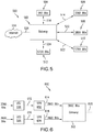
- FIG. 5 illustrates an example system 500 in accordance with aspects of the present invention.
- system 500 includes a gateway 502, a user terminal 504, a user terminal 506, a user terminal 508, a user terminal 510, a user terminal 512, and the internet 514.
- User terminal 504 is arranged to send code blocks, which are 960 bits in length, to gateway 502 along bi-directional transmission line 516.
- User terminal 506 is arranged to send code blocks, which are 3360 bits in length, to gateway 502 along bi-directional transmission line 518.
- User terminal 508 is arranged to send code blocks, which are 3600 bits in length, to gateway 502 along bi-directional transmission line 520.
- User terminal 510 is arranged to send code blocks, which are 5760 bits in length, to gateway 502 along bi-directional transmission line 522.
- User terminal 512 is arranged to send code blocks, which are 6720 bits in length, to gateway 502 along bi-directional transmission line 524.
- each user terminal is transmitting discrete code blocks of a certain length.
- each user terminal is operable to transmit a plurality of code block lengths, which are dependent on the amount of information to be transmitted.
- Gateway 502 is arranged to send and receive data from, bi-directional transmission line 516 from user terminal 504, bi-directional transmission line 518 from user terminal 506, bi-directional transmission line 520 from user terminal 508, bi-directional transmission line 522 from user terminal 510, and bi-directional transmission line 524 from user terminal 512.
- Gateway 502 is additionally arranged to send encoded data stream 526 to internet 514.
- a user will send code blocks of a certain length to gateway 502.
- Each individual user terminal encodes the data with an LDPC encoder and sends the encoded blocks to gateway 502.
- Gateway 502 contains architecture for each respective mother code that it supports.
- gateway 502 contains architecture for mother codes, the lengths of which are 960 bits, 3600 bits, and 5760 bits.
- Code blocks transmitted by UT1 504, UT3 506, and UT4 510 are able to be transmitted easily due to the fact that the code blocks are of a length that corresponds to a supported mother parity check matrix, and do not need to undergo any manipulation.
- Code blocks from UT2 506 and UT5 512 are not of a length that is readily usable by gateway 502 and therefore have to be either shorten, punctured and repeated or padded to a length that corresponds to a mother parity check matrix which is further described with reference to FIG. 6 .
- gateway 502 When gateway 502 receives the encoded LDPC code blocks, it decodes them using an LDPC decoder that has a length that is common to all incoming code block lengths.
- the LDPC decoder runs an iterative process to decode each incoming code block of any length and obtain the originally transmitted data.
- gateway 502 wants to send data to a user terminal the process is reversed.
- gateway 502 wants to send data to a user terminal, it uses an LDPC encoder to encode the data. Once the data is encoded, the encoded code blocks are transmitted to a user terminal, which then decodes the code blocks to obtain the originally transmitted data.
- FIG. 6 illustrates the shortening, puncturing, and repeating (SPR) of code block length to a length corresponding to a supported LDPC code by using a mother parity check matrix.
- system 600 includes gateway 502, UT2 506, UT3 508, SPR portion 602, SPR portion 604.
- UT2 506 is arranged to send data blocks, 3360 bits in length, to SPR portion 802.
- UT3 508 is arranged to send data blocks, 3600 bits in length, to SPR portion 604.
- Gateway 502 is arranged to receive data blocks that are 3600 bits in length and to send data blocks 3600 bits in length to a receiver via internet connection 620.
- a user using UT3 508 will send data to a receiver (not shown).
- the code blocks that UT3 508 sends out are 3600 bits in length, which is received by SPR portion 604.
- SPR portion 604 has a list of LDPC codes, the code block length of the supported LDPC codes, and their mother parity check matrices used by gateway 502.
- the supported LDPC code is associated with a code block whose bit length is 3600.
- SPR portion 604 will receive the code block sent by UT3 508 and cross reference the code block length with code block lengths that are associated with the supported LDPC codes contained by gateway 502. In this case SPR portion 604 finds that the code block sent by UT3 508 is compatible with a LDPC code supported by gateway 502 and sends the code block to the gateway without any code block length manipulation.
- a user using UT2 506 will send data to a receiver (not shown).
- the code blocks that UT2 506 sends out are 3360 bits in length, which is received by SPR portion 602.
- SPR portion 602 has a list of code block sizes that are associated with LDPC codes supported by gateway 502. In this example, the supported block size is 3600 bits in length.
- the code block sent by UT2 506 is too small to be used by a mother LDPC code and the LDPC code for a code block 3360 bits in length must be derived from a supported mother parity check matrix by shortening, puncturing, and repeating.
- a code block of k 2 bits must first be accepted. Once the code block has been received, k 1 -k 2 dummy bits must be added to the code block of length k 2 to obtain a code block of length k 1 . At this time, the code block of length k 2 has been transformed into a code block of length k 1 , which enables the use of the existing ( n 1 ,k 1 ) LDPC code to obtain n 1 coded bits.
- n 1 - ( k 1 -k 2 ) bits The number of coded bits left after the removal of the dummy bits is n 1 - ( k 1 -k 2 ) bits. Finally n 1 - ( k 1 -k 2 ) -n 2 bits must be punctured from the remaining coded bits to obtain n 2 bits.
- UT2 506 is sending code blocks of 3360 bits at a code rate of 1/2 (i.e., the ratio of information bits to coded bits is 1/2), so the LDPC code that is desired is denoted as ( 6720/3360 ). Since the code block does not have a supported LDPC code, it needs to be derived using a mother parity check matrix of a LDPC code that is supported. In this case the existing LDPC code is denoted as ( 7200/3600 ).
- the 3360 bits are accepted.
- 240 dummy bits are added to the 3360 information bits to obtain a code block that is 3600 bits in length.
- a code block of 7200 bits is derived.
- the 240 dummy bits that were added to the original code block of 3360 bits are still contained within the 7200 bit code block. Removing the dummy bits a code block of 6960 bits is obtained. Since a code block of 6720 bits is desired, another 240 bits must be punctured to obtain 6720 bits as desired. After a code block of 6720 bits has been derived, SPR portion 602 will send the coded bits to gateway 502. Once the code has been received by gateway 502, the code can be reconstructed using the mother parity check matrix to recover the bits that were punctured out of the code block.
- punctured bits should be chosen among the parity bits, whereas for high code rates such as 8/9 and 9/10, punctured bits should be chosen among the systematic bits to minimize performance loss.
- Shortening, puncturing, and repeating provides a method for coding and transmitting blocks of an intermediate size. This method allows the transmission of code blocks that may not be associated with a supported mother LDPC code.
- the code block derived is 6720 bits in length, which is larger than the maximum implemented block size of 5720 bits.
- more than one code block needs to be sent to transmit all of the user's data.
- One method would be to transmit a block size of 5760 bits and another block size of 960 bits. This choice, would have poor performance due to the short block size of 960 bits because the shorter the block size the more transmit power per bit is needed.
- An optimum choice would be two 3360 bit blocks, because reliability and efficiency are optimized.
- the transmitted block sizes should be chosen such that the minimum transmitted size is maximized. This rule applies even if the number of transmitted block sizes is more than two.
- the two 3360 bit blocks are sent by making use of the 3600 bit mother blocks.
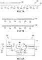
- FIG. 7A and FIG. 7B illustrate the transmission of a data stream length that is not supported by receiver hardware in accordance with aspects of the present invention.
- system 700 includes supported data stream length 702, data stream 704, a data packet 706, and a data packet 708.
- Supported data stream length 702 is the length of 6 data packets, each of which is 560 bits in length.
- Data stream 704 is comprised of 12 individual data packets, data packet 710 through data packet 732, each of which is 560 bits in length.
- Data packet 706 and data packet 708 can each hold 6 individual packets of data, each of which are 560 bits in length. Data packet 706 and data packet 708 are of the same length as data stream 702, the length of which is supported by the receiver hardware.
- data stream 704 is 6720 bits in length which is too large to fit into the largest supported data packet of 5720 bits. Therefore, data stream 704 needs to be converted into data stream lengths that can be put into packet sizes that are supported by the receiver hardware. Since data stream 704 is too long to fit into a supported data packet size, it needs to be divided into smaller lengths that will fit into a supported data packet size that will then be transmitted.
- FIG. 7B illustrates an example data stream that has been divided into smaller stream lengths which are able to fit into data packets which are supported by the receiver hardware.
- data stream 704 has been divided into two equal lengths, each of which is small enough to fit into data packet 706 and data packet 708.
- Data packet 786 and data packet 706 are filled with six individual data packets from data stream 704. Once data packet 706 and data packet 708 are filled with information from data stream 704, they are ready to be transmitted to the receiver.
- each data packet has the longest possible length without using dummy bits, because the larger the packets size, the more efficient the transmission.
- gateway 502 is able to transmit the code blocks to its intended destination.
- gateway 502 wants to send data to a user terminal the process is reversed.
- gateway 502 wants to send data to a user terminal, it uses an LDPC encoder to encode the data. Once the data is encoded, the encoded code blocks are transmitted to a user terminal, which then decodes the code blocks to obtain the originally transmitted data.
- FIG. 8A illustrates gateway 502 at time t 1 in accordance with aspects of the present invention.
- system 800 includes a receiver portion 802, a low density parity check portion (LDPC) 804, a controller 806, and a transmitter 808.
- LDPC low density parity check portion
- Receiver 802 is arranged to receive incoming data signal 810.
- LDPC portion 804 is arranged to receive data via data signal 812 from receiver 802. LDPC portion 804 is additionally arranged to send controller alert 814 to controller 806 and receive enable signal 816. LDPC portion 804 is additionally arranged to send encoded data 818 to transmitter 808.
- encoded data is sent to the encoder by a first user terminal (UT1) 822.
- UT1 822 reaches the encoder through incoming data signal 810. (Note that there may be a plurality of signals coming in from different user terminals.)
- LDPC portion 802 decodes the encoded data.
- UT 1 822 that is received by receiver 802 is sent to LDPC portion 804 via data signal 812.
- LDPC portion 804 sends controller alert signal 814 to controller 806.
- Controller alert signal 814 tells controller 806 that LDPC portion 804 has received data and is ready to encode it.
- controller 806 sends enable signal 816 to LDPC portion 804. Once the signal is received, LDPC portion 804 begins encoding data as described in FIG. 6 . Once LDPC portion 804 has encoded the data, it breaks the data up into pieces such that the minimum transmitted size is maximized, then the data is put into packets.
- EUT 1 824 is sent to transmitter 808. At this point transmitter 808 sends EUT 1 824 to a receiver via internet connection 820.
- FIG. 8B illustrates encoder 502 at time t 2 in accordance with aspects of the present invention.
- encoder system 800 has already received UT1 822, encoded it, and transmitted it as EUT1 824.
- Now encoder 502 is receiving user terminal 2 data (UT2) 826 via incoming data signal 810.
- Encoder 502 follows the same process as before, receiver 802 sends UT2 826 to LDPC 804 via data signal 812. Again, LDPC portion 804 alerts controller 806 via controller alert signal 814, that it has received data and is ready to encode it. Controller 806 then sends enable signal 816 to LDPC portion 804, allowing it to encode UT2 826 and then send it to transmitter 808 as encoded second user terminal data (EUT2) 828.
- EUT2 encoded second user terminal data
- LDPC 804 encodes then breaks up the data into pieces such that the minimum transmitted size is maximized and then puts it into packets to be transmitted. After the data is encoded and put into packets it becomes encoded second user terminal data (EUT2) 828. EUT2 828 is sent to transmitter 808, where EUT2 828 is sent to a receiver via internet connection 820.
- EUT2 828 is sent to transmitter 808, where EUT2 828 is sent to a receiver via internet connection 820.
- a decoder for use with a first low density parity check code block having a first bit length and a second low density parity check code block having a second bit length.
- the decoder may store the first low density parity check code block and then use a processing engine to process the stored low density parity check code block based on the address of the first code block.
- the decoder may store the second low density parity check code block and then use a processing engine to process the stored low density parity check code block based on the address of the second code block.
- a decoder in accordance with the third aspect of the present invention includes a first memory portion that contains a first LDPC code block and a second memory portion that contains a second LDPC code block.
- the decoder will decode the first and second code blocks by using a third LDPC code that is common to both the first and second code blocks.
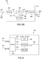
- FIG. 9 illustrates the use of common decoder architecture for different code rates and block sizes in accordance with aspects of the present invention.
- system 900 includes, a decoder 902, a LDPC portion 904, an address table 906, an address table 908, and a processor 910.
- Decoder 902 is arranged to receive incoming encoded data from signal 912 and signal 914. Decoder 902 is operable to store incoming encoded data in either address table 906 or address table 908.
- LDPC portion 904 is arranged to send decoding information to decoder 902.
- Address table 906 and address table 908 are arranged to receive and store data sent by decoder 902.
- Processor 910 is operable to process information stored in either address table 906 or address table 908. Processor 910 is additionally operable to send data to a receiver via signal 924.
- encoded data is sent to decoder 902 from an outside source (not shown).
- the encoded data received will be in a length that is supported by the decoder.
- the block are 120 bits in length and 600 bits in length, but in use incoming data may be in many different supported lengths.
- code block lengths that are supported by LDPC portion 904 are 22 bits and 40 bits in length. Since 22 is not a factor of 120 or 600 it cannot be used, but because 40 is a common factor of both 120 and 600, it can be used to decode the incoming encoded data. Note that in this example LDPC portion 904 only supports two code block lengths but in practice it may support many code block lengths.
- a 600 bit block has an LDPC code rate of 9/10, such that it has 600 bit nodes and 60 check nodes.
- 60 hardware processing engines may be implemented to process this code.
- 60 hardware processing engines may not be a very good choice.
- an LDPC code rate of 4/5 is desired to be supported for a 120 bit block, then 36 of the 60 hardware processing engines would be idle.
- decoder 902 sends the encoded data that is 120 bits in length to address table 906 and it sends encoded data that is 600 bits in length to address table 908.
- Code blocks of different lengths are sent to different address tables because a different matrix is used to decode each respective code block.
- the parity check matrix used to encode code blocks 120 bits in length is also used to decode code blocks that are 120 bits in length.
- the parity check matrix used to encode code blocks 600 bits in length is also used to decode 600 bits in length. Segregating code blocks in to address tables for each length indicates to processor 910 which decoding matrix should be used.
- Simultaneously decoder 902 sends the common LDPC code to processor 910 which will be used to decode the encoded information stored in address table 906 and address table 908.
- Processing engine 910 takes encoded data from address table 906, which is 120 bits in length, and begins decoding the data. Since the LDPC decoding information is smaller than the block sizes stored, it must run the encoded data through an iterative process. With a 40 bit LDPC code, 120 bit code blocks must be run through the decoding process 3 times.
- processing engine 910 is decoding encoded data from address table 908, which is 600 bits in length, it must run the code blocks through an iterative process 15 times.
- processing engine 910 Once processing engine 910 has decoded the data from address table 906 and address table 908 it can send the data to a receiver (not shown) via signal 924.
- System 500 in accordance with aspects of the present invention, provides a method for large block and intermediate block size support as well as a means for using common decoder architecture for different code rates and block size.
- a benefit of the present invention can be seen when looking at configuration 800.
- transmission of data has been optimized in regards to reliability and energy consumption. Optimization is achieved by choosing the transmitted block sizes such that the minimum transmitted size is maximized.
Landscapes
- Physics & Mathematics (AREA)
- Engineering & Computer Science (AREA)
- Probability & Statistics with Applications (AREA)
- Theoretical Computer Science (AREA)
- Mathematical Physics (AREA)
- Computer Networks & Wireless Communication (AREA)
- Signal Processing (AREA)
- Error Detection And Correction (AREA)
Abstract
Description
- Forms of communication and data transmission make use of low-density parity-check codes (LDPC). LDPC codes are a form of linear error correcting code, which are used to transmit messages over a noisy transmission channel.
- When a transmitter uses an LDPC code to encode data, it encodes it in a redundant form. This redundancy allows the receiver to detect a limited number of errors that may occur anywhere in the message, and also allows the receiver to correct these errors without retransmission of data.
- LDPC codes are powerful block codes whose performances get close to Shannon capacity as their block size increases. As a result, efficient and high performing LDPC codes have been standardized by several standardization bodies, the first being DVB-S2. In DVB-S2 two different coded block sizes have been used: 64800 and 16200 bits.
- LPDC codes are finding increasing use in applications where reliable and highly efficient information transfer over bandwidth in the presence of data-corrupting noise. LPDC codes are currently utilized in digital video broadcasting, microwave communications, cell phone communications, and Wi-Fi.
-
FIG. 1 illustrates anexample system 100. - As illustrated in the
figure system 100 includes agateway 102, auser terminal 104, auser terminal 106, auser terminal 108, auser terminal 110, auser terminal 112, and theinternet 114. -
User terminal 104 is arranged to send code blocks, which are 120 bits in length, togateway 102 along bi-directionaltransmission line 116. -
User terminal 106 is arranged to send code blocks, which are 240 bits in length, togateway 102 along bi-directionaltransmission line 118. -
User terminal 108 is arranged to send code blocks, which are 360 bits in length, togateway 102 along bi-directionaltransmission line 120. -
User terminal 110 is arranged to send code blocks, which are 480 bits in length, togateway 102 along bi-directionaltransmission line 122. -
User terminal 112 is arranged to send code blocks, which are 600 bits in length, togateway 102 along bi-directionaltransmission line 124. - For purposes of discussion, in this example, each user terminal is transmitting discrete code blocks of a certain length. In practice, each user terminal is operable to transmit a plurality of code block lengths, which are dependent on the amount of information to be transmitted.
-
Gateway 102 is arranged to send and receive data from, bi-directionaltransmission line 116 fromuser terminal 104, bi-directionaltransmission line 118 fromuser terminal 106, bi-directionaltransmission line 120 fromuser terminal 108, bi-directionaltransmission line 122 fromuser terminal 110, andbi-directional transmission line 124 fromuser terminal 112. Gateway 102 is additionally arranged to send encodeddata stream 126 tointernet 114. - Gateway 102 contains a LDPC code and architecture for each respective code block length that it supports. In this example,
gateway 102 contains an LDPC code and architecture set for each of the code block it supports, the lengths of which are 120 bits, 240 bits, 360 bits, 480 bits, and 600 bits. - In operation, a user will send code blocks to
gateway 102 from a user terminal. Each individual user terminal encodes the data with an LDPC encoder and then sends the encoded data blocks togateway 102. - When
gateway 102 receives the encoded LDPC code blocks, it decodes them using an LDPC decoder to obtain the originally transmitted data. Note that whengateway 102 wants to send data to a user terminal the process is reversed. - When
gateway 102 wants to send data to a user terminal, it uses an LDPC encoder to encode the data. Once the data is encoded, the encoded code blocks are transmitted to a user terminal, which then decodes the code blocks to obtain the originally transmitted data. Once the data is encoded, it may be sent tointernet 112 viainternet connection 126. - Data being sent over a noisy channel needs to be sent in a secure form. When a transmission channel is noisy it is much easier to lose data during transmission. This can create difficulties because of transmission control protocol (TCP).
- Each data packet that is sent has a sequence number that is used to reconstruct the transmitted data in the correct order. For successful communication, the reliability of each packet (i.e. robustness against the channel noise) needs to be similar.
- Another difficulty to consider during data transmission is that of power consumption. The larger a data packet is, the less energy per bit is consumed during transmission. This is due to the fact that the performance of modern error correcting codes, such as LDPC or turbo codes, improves with increasing block size. For very large data streams it becomes very important to try and minimize energy consumption.
- For example, if a user wants to send a data stream that is 120,000 bits long, it would be much more efficient to send 20 packets that are 6000 bits in length than it would be to send 3000 packets that are 40 bits in length.
- Data streams that are being transmitted first need to be configured into a data stream length that is supported be the receiver it is being sent to. This will be further illustrated by
FIGs. 2-4B . -
FIG. 2 illustrates an example of various data stream lengths as well as supported data stream lengths ofsystem 200. - As illustrated in the
figure system 200 includes data stream sizes that are integer multiples of 120 bits.Data stream 202,data stream 206,data stream 212,data stream 222, anddata stream 230 represent the data stream lengths that are supported by the system hardware. -
Data stream 202 throughdata stream 230 represents all possible incoming data stream lengths. Note that it is possible of for an incoming data stream to exceed the possible supported data stream size but for the purposes of discussion there is a cut off at 1800 bits represented bydata stream 230. -
FIG. 3A and FIG. 3B illustrates the transmission of a data stream size that is not supported by the receiver hardware. - As illustrated in
FIGs. 3A- 3B system 300 includes supporteddata stream 222,data stream length 224, adata packet 326 and adata packet 328. Supporteddata stream length 222 is the length of 11 data packets, each of which is 120 bits in length.Data stream 224 is comprised of 12 individual data packets,data packet 302 throughdata packet 324, each of which is 120 bits in length. -
Data packet 326 is a packet that can hold 11 data packets each of which are 120 bits in length.Data packet 328 is a packet that can hold 11 data packets each of which are 120 bits in length. - In operation,
data stream 224 needs to be converted into a data stream, of two or more pieces, with lengths that can be put into data packets that are supported by the receiver hardware. Sincedata stream 224 is too long to fit intodata packet 322, it needs to be divided up into smaller lengths that will fit into a supported data packet size that will then be transmitted. - The division of
data stream 224 into smaller lengths to fit into supported data packet sizes will be further discussed in reference toFIG. 3B . -
FIG. 3B illustrates an example data stream that has been divided into smaller stream lengths that can fit into data packets which are supported by the receiver hardware. - In operation,
data stream 224 has been divided into two lengths, which are small enough to fit into supporteddata packet 326 anddata packet 328, both of which are the same length as supporteddata packet 222.Data packet 326 is filled withdata packet 302 throughdata packet 322 fromdata stream 224 leavingdata packet 324 left over. -
Data packet 328 containsdata packet 324 fromdata stream 224 but is otherwise empty. Since a data packet can't be sent unless it is full, the open space is filled with dummy bits. Dummy bits do not affect the content ofdata packet 328; they are simply placed indata packet 328 to fill it so it may be transmitted. - At this point,
data stream 224 has been divided into two smaller lengths that have been put intodata packet 326 anddata packet 328, and they are ready to be transmitted to the receiver. -
FIG. 4A and FIG. 4B illustrate the transmission of a data stream length that is not supported by receiver hardware. - As illustrated in
FIGs. 4A-4B system 400 includes supporteddata stream length 206,data stream 224, adata packet 402, adata packet 404, adata packet 406, and adata packet 408. Supporteddata stream length 206 is the length of 3 data packets, each of which is 120 bits in length.Data stream 224 is comprised of 12 individual data packets,data packet 302 throughdata packet 324, each of which is 120 bits in length. -
Data packet 402,data packet 404,data packet 406, anddata packet 408 can each hold 3 packets of data, each of which are 120 bits in length. - In operation,
data stream 224 needs to be converted into a data stream lengths that can be put into packet sizes that are supported by the receiver hardware. Sincedata stream 224 is too long to fit intodata packet 402, it needs to be divided up into smaller lengths that will fit into a supported data packet size that will then be transmitted. - The division of
data stream 224 into smaller lengths to fit into supported data packet sizes will further be discussed in reference toFIG. 4B . -
FIG. 4B illustrates an example data stream that has been divided into smaller stream lengths which are able to fit into data packet which are supported by the receiver hardware. - In operation,
data stream 224 has been divided into 4 equal lengths, each of which are small enough to fit intodata packet 402,data packet 404,data packet 406, ordata packet 408. Each data packet is filled with information fromdata stream 224. - Once
data packet 402,data packet 404,data packet 406, anddata packet 408 are filled with information fromdata stream 224, they are ready to be transmitted to the receiver. - There are several problems with the current methods when utilizing LDPC codes. The first problem is that of large block size support as shown in
FIGs. 3A-4B . A code block may sometimes need to be very small and sometimes very large. - If only a large block size was implemented, a lot of transmission capacity would be wasted when the user had only a small amount of data to send. Conversely, if only a small block size was implemented, more power would be used than necessary when the user had a large amount of data to send since the performance of iterative decoding systems improve as the block size increases.
- Even though a user may have an arbitrarily large amount of data to send occasionally, it would not be practically feasible to implement arbitrarily large block sizes. That's because the complexity of iterative receivers increases almost linearly with increasing block sizes.
- Another problem with the current methods of utilizing LDPC codes, is the lack of intermediate block size support as shown in
FIG. 1 . If one wants to support many different code block lengths that it may be undesirable to design a separate LDPC code for each block length. - The final problem with the current methods for utilizing LDPC codes as shown in
FIG. 1 is the space that is taken up by the architecture used for each LDPC code. If one wants to support many different code block lengths, an LDPC code and its respective architecture needs to be implemented in the hardware design for each individual code block length. - To support many different code block lengths, the architecture needed to support each individual code block length begins to be problematic. As the number of architectures being implemented for each code block length, the complexity of the hardware design increases as well.
- The increase in complexity, for each supported code block length, is too high when attempting to design hardware that is capable of supporting many code block lengths.
- What is needed is a system and method to address the problem of large block size support. The transmitted block sizes need to be chosen so that the minimum transmitted size is maximized. This means that when a user wants to transmit more data than the maximum supported block size, the transmitted block sizes should be as large as possible without having empty space in the transmitted block.
- What is needed is a system and method to address the problem of intermediate block size support. To address intermediate block size support, bits in the code should be shortened, punctured, and repeated to derive intermediate code block lengths. On the other hand, the location of punctured bits should be carefully chosen in order not to cause substantial performance loss. What is needed is a system and method for using common decoder architecture for different code rates and block sizes. It may also be desirable to use the same piece of hardware to decode all block sizes and all code rates with the help of a code-specific set of parameters. This will reduce the complexity of the receiver where a different decoder is used for different codes.
- The present invention provides a system and method for supporting large block sizes. By choosing to transmit incoming data blocks such that, the minimum transmitted size is maximized, one can transmit blocks reliably and efficiently despite the original code block being too large to be supported.
- The present invention additionally provides a system and method for supporting intermediate block sizes. Through puncturing, shortening, and repeating incoming code blocks as indicated by a parity check matrix it is possible to create code blocks of an intermediate length.
- The present invention additionally provides a system and method for using common decoder architecture for different code rates and block sizes. By using a hardware architecture that is common to all code blocks, it is possible to support many different codes by running them through an iterative process utilizing the architecture common to all code blocks.
- In accordance with an aspect of the present invention, a method is provided for supporting code blocks of any length and converting them into code blocks that are large or intermediate in length, which are compatible with a system's hardware. A method is also provided for using a common decoder architecture for processing all incoming code blocks.
- In accordance with an aspect of the present invention, an encoder is provided to encode a string of information bits having a bit length k into a string of encoded bits having a bit length N. The encoder includes a plurality of LDPC portions and a controller. Each of the LDPC portions can encode a portion of the information bits into a LDPC code block, respectively, wherein each of the respective LDPC code blocks has a different bit length. The controller can instruct a number of the LDPC portions to encode the information bits into a plurality of LDPC code blocks such that the minimum encoded block size is maximized.
- In accordance with another aspect of the present invention, an encoder is provided to encode a string of information bits having a bit length k into a string of encoded bits having a bit length N. The encoder includes a LDPC portion and a controller. The LDPC portion can encode information bits into LDPC code blocks, wherein each of the LDPC code blocks has a bit length S1 . When N < S1, the LDPC portion can do at least one of pad, shorten, puncture or repeat a bit within one of the string of information bits and parity bits associated with the string of information bits to create an encoded LDPC code block having a length N.
- In accordance with another aspect of the present invention, a decoder is provided for use with a first LDPC code block and a second LDPC code block. The first low LDPC block has a first bit length, and the second LDPC block has a second bit length, wherein the first bit length is shorter than the second bit length. The decoder includes a receiving portion, a memory portion an address table portion, a processing engine and a controller. The receiving portion can receive a code block. The memory portion can store the first low density parity check code block as a first data structure and can store the second low density parity check code block as a second data structure. The address table portion has a first address table stored therein and has a second address table stored therein. The first address table relates a structure of the first LDPC code block to the first data structure, whereas the second address table relates a structure of the second LDPC code block to the second data structure. The processing engine can process blocks of data having a third bit length, wherein the third bit length is shorter than the first bit length. When the code block is the first low density parity check code block, the controller can instruct the memory portion to store the first LDPC code block as the first data structure and can instruct the processing engine to process the blocks of data within the stored first LDPC code block based on the first address table. When the code block is the second LDPC code block, the controller can to instruct the memory portion to store the second LDPC code block as the second data structure and can instruct the processing engine to process the blocks of data within the stored second LDPC code block based on the second address table.
- Additional advantages and novel features of the invention are set forth in part in the description which follows, and in part will become apparent to those skilled in the art upon examination of the following or may be learned by practice of the invention. The advantages of the invention may be realized and attained by means of the instrumentalities and combinations particularly pointed out in the appended claims.
- The accompanying drawings, which are incorporated in and form a part of the specification, illustrate an exemplary embodiment of the present invention and, together with the description, serve to explain the principles of the invention. In the drawings:
-
FIG. 1 illustrates an example gateway and user terminals for a prior art configuration; -
FIG. 2 illustrates various data stream lengths as well as supported data stream lengths; -
FIG. 3 illustrates the use of packets that are too large for a given data stream length for the prior art ofFIG. 1 ; -
FIG. 4 illustrates the division of a data stream into many smaller lengths for the prior art ofFIG. 1 ; -
FIG. 5 illustrates an example gateway and user terminal configuration, in accordance with aspects of the present invention; -
FIG. 6 illustrates the shortening, puncturing, and repeating of a code block, in accordance with aspects of the present invention; -
FIG. 7 illustrates the optimization of data stream division, in accordance with aspects of the present invention; -
FIG. 8 illustrates the gateway operation of the configuration described inFIG. 5 , in accordance with aspects of the present invention; and -
FIG. 9 illustrates the use of common decoder architecture, in accordance with aspects of the present invention. - Aspects of the present invention provide a method for supporting large code block lengths. In contrast with the embodiment of
FIGs. 2-4B , code blocks that are larger than the supported code block length available are broken up into small pieces in such a way that the minimum transmitted size is maximized. - In contrast to the prior art system described above, where the code blocks were either broken up into many small pieces or pieces of random length, and were then sent out to a receiver. These two methods were unreliable and inefficient.
- Now the code blocks are now broken up into the largest possible size that can be transmitted without having wasted space. The intelligent decision to choose the block size to be transmitted such that they are as large as possible without having empty space, optimizes reliability and efficiency.
- Choosing large block sizes exploits the fact that power is more efficiently utilized when sending large block sizes. Additionally, this decision can provide the desired degree of reliability for successful transmission of code blocks.
- Aspects of the present invention provide a method for supporting intermediate code block lengths. Practical LDPC codes of interest have structured parity check matrices, therefore their storage is relatively much easier than random parity check matrices. On the other hand, in some applications, the number of desired parity check matrices may be so large that designing a separate LDPC codes for each block size may be undesirable.
- In these cases, it may be possible to design a certain number of mother parity check matrices and derive the intermediate codes by shortening, puncturing or repeating. Provided the number of shortened, punctured or repeated bits is not excessive with respect to the original block size, performance loss would not be significant by carefully choosing the location of the affected bits.
- The general rule provided, in accordance with aspects of the present invention, states that for lower code rates such as 1/2, 2/3 and 4/5 punctured bits should be chosen among the parity bits, whereas for high code rates such as 8/9 and 9/10, punctured bits should be chosen among the systematic bits to minimize the performance loss.
- Aspects of the present invention provide a method for using common decoder architecture for different code rates and block sizes. As previously discussed, in
prior art system 100, the current method for supporting many different code block lengths adds an undesired amount of complexity to a system. - Currently, a separate LDPC code and piece of architecture is implemented to support each different code block length and code rate, while not problematic when supporting a limited number of code blocks, designs become extremely complex when attempting to support many code blocks.
- The present invention provides a method for finding a common decoder architecture, and then using the architecture to support all the code blocks.
- A fully parallel LDPC decoder implementation would have as many bit nodes as the number of coded bits and as many check nodes as the number of parity check equations. While this implementation would have very high speeds, it would be extremely complex. Moreover it may need to have as many instantiations of the decoder as the number of parity check matrices that would be implemented.
- A more practical approach may be to implement a partially parallel decoder where a certain number M of physical parallel engines would process M logical nodes of the LDPC codes at a time. This approach not only simplifies the decoder significantly, but also allows to support all of the different parity check matrices using a common decoder hardware, provided the same inherent structure is kept among all of the codes. Only a code specific table would change whenever a new parity check matrix is deployed. This table would tell the decoder parallel engines where to access the relevant edges for the logical nodes being processed.
- The number of parallel engines M influence the decoder speed and complexity, and it is determined by the code design. When a set of different parity check matrices is supported with a common hardware, the number of physical nodes has to be as large as the maximum M among all of the codes. Therefore in order not to waste the decoder area for certain codes, M for different parity check matrices should be as close to one another as possible.
- The first two aspects of the present invention will now be described in greater detail with reference to
FIGs. 5-8 . - In accordance with the first aspect, an encoder is provided to encode a string of information bits having a bit length k into a string of encoded bits having a bit length N. The encoder includes a plurality of LDPC portions. Each LDPC portion can encode a portion of the information bits into a LDPC code block, respectively, wherein each of the respective LDPC code blocks has a different bit length. The encoder additionally includes a controller that can instruct a number of the LDPC portions to encode the information bits into a plurality of LDPC code blocks such that the minimum encoded block size is maximized.
- For example, suppose for purposes of discussion that an encoder in accordance with second aspect of the present invention includes a controller that instructs an encoder to encode a string of information bits using an LDPC portion. For purposes of discussion, presume that in this example that the string of information bits has a length k=6720 bits. If the largest LDPC portion is only 5760 bits, the string of information bits must be broken into two separate pieces. The controller will determine the optimum LDPC portion to be used to encode the information bits based on performance considerations.
- In this example, the controller would instruct an LDPC portion that was 3360 bits in length to encode the string of information bits. This choice would minimize the amount of dummy bits that were needed to fill each code block while simultaneously minimizing the amount of power needed to transmit each bit after being encoded.
- In accordance with the second aspect, an encoder is provided to encode a string of information bits having a bit length k into a string of encoded bits having a bit length N. The encoder includes an LDPC portion and a controller. The LDPC portion can encode the information bits into LDPC code blocks, each of which has a bit length S1 . When N < S1, the LDPC portion can pad, shorten, puncture or repeat a bit within one of the string of information bits and parity bits associated with the string of information bits to create an encoded LDPC code block having a length N.
- For example, returning to
FIG. 2 , suppose for purposes of discussion that an encoder in accordance with second aspect of the present invention includes a first LDPC portion that can encode information bits into LDPC code blocks corresponding to data stream length 222 (in this casedata stream length 222 corresponds to S1 ). In accordance with the present invention, if a data stream length corresponding to data stream length 220 (in this casedata stream length 220 corresponds to N, in which N < S1 ) were needed to be encoded, then LDPC portion would be able to pad, shorten, puncture or repeat a bit within one of the string of information bits and parity bits associated with the string of information bits indata stream length 220 to create an encoded LDPC code block having a length corresponding to data stream length 222 (in this casedata stream length 222 corresponds to S1). -
FIG. 5 illustrates anexample system 500 in accordance with aspects of the present invention. - As illustrated in the
figure system 500 includes agateway 502, auser terminal 504, auser terminal 506, auser terminal 508, auser terminal 510, auser terminal 512, and theinternet 514. -
User terminal 504 is arranged to send code blocks, which are 960 bits in length, togateway 502 alongbi-directional transmission line 516. -
User terminal 506 is arranged to send code blocks, which are 3360 bits in length, togateway 502 along bi-directional transmission line 518. -
User terminal 508 is arranged to send code blocks, which are 3600 bits in length, togateway 502 alongbi-directional transmission line 520. -
User terminal 510 is arranged to send code blocks, which are 5760 bits in length, togateway 502 alongbi-directional transmission line 522. -
User terminal 512 is arranged to send code blocks, which are 6720 bits in length, togateway 502 alongbi-directional transmission line 524. - For purposes of discussion, in this example embodiment, each user terminal is transmitting discrete code blocks of a certain length. In practice, each user terminal is operable to transmit a plurality of code block lengths, which are dependent on the amount of information to be transmitted.
-
Gateway 502 is arranged to send and receive data from,bi-directional transmission line 516 fromuser terminal 504, bi-directional transmission line 518 fromuser terminal 506,bi-directional transmission line 520 fromuser terminal 508,bi-directional transmission line 522 fromuser terminal 510, andbi-directional transmission line 524 fromuser terminal 512.Gateway 502 is additionally arranged to send encodeddata stream 526 tointernet 514. - In operation, a user will send code blocks of a certain length to
gateway 502. Each individual user terminal encodes the data with an LDPC encoder and sends the encoded blocks togateway 502. -
Gateway 502 contains architecture for each respective mother code that it supports. In this example,gateway 502 contains architecture for mother codes, the lengths of which are 960 bits, 3600 bits, and 5760 bits. Code blocks transmitted byUT1 504,UT3 506, andUT4 510 are able to be transmitted easily due to the fact that the code blocks are of a length that corresponds to a supported mother parity check matrix, and do not need to undergo any manipulation. - Code blocks from
UT2 506 andUT5 512 are not of a length that is readily usable bygateway 502 and therefore have to be either shorten, punctured and repeated or padded to a length that corresponds to a mother parity check matrix which is further described with reference toFIG. 6 . - When
gateway 502 receives the encoded LDPC code blocks, it decodes them using an LDPC decoder that has a length that is common to all incoming code block lengths. The LDPC decoder runs an iterative process to decode each incoming code block of any length and obtain the originally transmitted data. - Note that when
gateway 502 wants to send data to a user terminal the process is reversed. Whengateway 502 wants to send data to a user terminal, it uses an LDPC encoder to encode the data. Once the data is encoded, the encoded code blocks are transmitted to a user terminal, which then decodes the code blocks to obtain the originally transmitted data. -
FIG. 6 illustrates the shortening, puncturing, and repeating (SPR) of code block length to a length corresponding to a supported LDPC code by using a mother parity check matrix. - As illustrated in the figure,
system 600 includesgateway 502,UT2 506,UT3 508,SPR portion 602,SPR portion 604. -
UT2 506 is arranged to send data blocks, 3360 bits in length, toSPR portion 802.UT3 508 is arranged to send data blocks, 3600 bits in length, toSPR portion 604. -
Gateway 502 is arranged to receive data blocks that are 3600 bits in length and to senddata blocks 3600 bits in length to a receiver viainternet connection 620. - In operation, a
user using UT3 508 will send data to a receiver (not shown). The code blocks thatUT3 508 sends out are 3600 bits in length, which is received bySPR portion 604.SPR portion 604 has a list of LDPC codes, the code block length of the supported LDPC codes, and their mother parity check matrices used bygateway 502. In this example, the supported LDPC code is associated with a code block whose bit length is 3600. -
SPR portion 604 will receive the code block sent byUT3 508 and cross reference the code block length with code block lengths that are associated with the supported LDPC codes contained bygateway 502. In thiscase SPR portion 604 finds that the code block sent byUT3 508 is compatible with a LDPC code supported bygateway 502 and sends the code block to the gateway without any code block length manipulation. - Simultaneously, a
user using UT2 506 will send data to a receiver (not shown). The code blocks thatUT2 506 sends out are 3360 bits in length, which is received bySPR portion 602.SPR portion 602 has a list of code block sizes that are associated with LDPC codes supported bygateway 502. In this example, the supported block size is 3600 bits in length. The code block sent byUT2 506 is too small to be used by a mother LDPC code and the LDPC code for acode block 3360 bits in length must be derived from a supported mother parity check matrix by shortening, puncturing, and repeating. - When a user wants to transmit a code block of a length that is not compatible with a supported LDPC code, an LDPC code must be shortened, punctured, and repeated to be made usable. This means that a (n2, k2 ) code with a code rate of R=k2 /n2 must be derived from a (n1,k1 ) code with a code rate of R=k1 /n1.
- To derive a (n2,k2 ) code, a code block of k2 bits must first be accepted. Once the code block has been received, k1-k2 dummy bits must be added to the code block of length k2 to obtain a code block of length k1. At this time, the code block of length k2 has been transformed into a code block of length k1, which enables the use of the existing (n1,k1 ) LDPC code to obtain n1 coded bits.
- Once the bits have been encoded, the k1-k2 dummy bits that were previously added in must be removed from the n1 coded bits. The number of coded bits left after the removal of the dummy bits is n1-(k1-k2 ) bits. Finally n1-(k1-k2 )-n2 bits must be punctured from the remaining coded bits to obtain n2 bits. The process of deriving an LDPC code through shortening, puncturing, and repeating will now be described.
-
UT2 506 is sending code blocks of 3360 bits at a code rate of 1/2 (i.e., the ratio of information bits to coded bits is 1/2), so the LDPC code that is desired is denoted as (6720/3360 7200/3600 - To begin deriving an LDPC code for a code block of 3360 bits and a rate of 1/2, the 3360 bits are accepted. 240 dummy bits are added to the 3360 information bits to obtain a code block that is 3600 bits in length. Using the supported LDPC code and associated parity check matrix, a code block of 7200 bits is derived.
- The 240 dummy bits that were added to the original code block of 3360 bits are still contained within the 7200 bit code block. Removing the dummy bits a code block of 6960 bits is obtained. Since a code block of 6720 bits is desired, another 240 bits must be punctured to obtain 6720 bits as desired. After a code block of 6720 bits has been derived,
SPR portion 602 will send the coded bits togateway 502. Once the code has been received bygateway 502, the code can be reconstructed using the mother parity check matrix to recover the bits that were punctured out of the code block. - In slower code rates such as 1/2, 2/3, and 4/5 the punctured bits should be chosen among the parity bits, whereas for high code rates such as 8/9 and 9/10, punctured bits should be chosen among the systematic bits to minimize performance loss.
- Shortening, puncturing, and repeating provides a method for coding and transmitting blocks of an intermediate size. This method allows the transmission of code blocks that may not be associated with a supported mother LDPC code.
- In this example, the code block derived is 6720 bits in length, which is larger than the maximum implemented block size of 5720 bits. In this case, more than one code block needs to be sent to transmit all of the user's data. One method would be to transmit a block size of 5760 bits and another block size of 960 bits. This choice, would have poor performance due to the short block size of 960 bits because the shorter the block size the more transmit power per bit is needed. An optimum choice would be two 3360 bit blocks, because reliability and efficiency are optimized. The transmitted block sizes should be chosen such that the minimum transmitted size is maximized. This rule applies even if the number of transmitted block sizes is more than two. In the above example, the two 3360 bit blocks are sent by making use of the 3600 bit mother blocks.
- The division of large code blocks in such a way that the minimum transmitted size is maximized will now be discussed further with respect to
FIGs. 7A-7B . -
FIG. 7A and FIG. 7B illustrate the transmission of a data stream length that is not supported by receiver hardware in accordance with aspects of the present invention. - As illustrated in
FIGs. 7A- 7B system 700 includes supporteddata stream length 702,data stream 704, adata packet 706, and adata packet 708. Supporteddata stream length 702 is the length of 6 data packets, each of which is 560 bits in length.Data stream 704 is comprised of 12 individual data packets,data packet 710 throughdata packet 732, each of which is 560 bits in length. -
Data packet 706 anddata packet 708 can each hold 6 individual packets of data, each of which are 560 bits in length.Data packet 706 anddata packet 708 are of the same length asdata stream 702, the length of which is supported by the receiver hardware. - Occasionally a user may have an arbitrarily large amount of data to send, it would not be practically feasible to implement arbitrarily large block sizes. This is because the complexity of iterative receivers increases almost linearly with increasing block sizes. On the other hand, performance does not improve indefinitely with increasing block sizes; after every block size increase, the performance (reduction in transmit power per bit) reduces until a point where further block size increase causes negligible performance improvement. Hence, a system design was chosen based on performance and complexity considerations, leading to a maximum supported block size of, for example, 5760 bits.
- In operation,
data stream 704 is 6720 bits in length which is too large to fit into the largest supported data packet of 5720 bits. Therefore,data stream 704 needs to be converted into data stream lengths that can be put into packet sizes that are supported by the receiver hardware. Sincedata stream 704 is too long to fit into a supported data packet size, it needs to be divided into smaller lengths that will fit into a supported data packet size that will then be transmitted. - The division of
data stream 704 into smaller lengths to fit into supported data packet sizes will further be discussed in reference toFIG. 7B . -
FIG. 7B illustrates an example data stream that has been divided into smaller stream lengths which are able to fit into data packets which are supported by the receiver hardware. - In operation,
data stream 704 has been divided into two equal lengths, each of which is small enough to fit intodata packet 706 anddata packet 708. Data packet 786 anddata packet 706 are filled with six individual data packets fromdata stream 704. Oncedata packet 706 anddata packet 708 are filled with information fromdata stream 704, they are ready to be transmitted to the receiver. - In this configuration, the transmission of
data stream 704 has been optimized in regards to reliability. With concerns relating to reliability, each data packet has equally and fully been filled with information fromdata stream 704. Elimination of the use of dummy bits provides the best and most reliable form of transmission of information. - Also in this configuration, the transmission of
data stream 704 has been optimized in regards to energy consumption. With concerns relating to energy consumption, each data packet has the longest possible length without using dummy bits, because the larger the packets size, the more efficient the transmission. - Once the code blocks being transmitted by a user have been shorten, punctured, and repeated using a mother LDPC code and divided into lengths that are supported by the receiver hardware,
gateway 502 is able to transmit the code blocks to its intended destination. - Note that when
gateway 502 wants to send data to a user terminal the process is reversed. Whengateway 502 wants to send data to a user terminal, it uses an LDPC encoder to encode the data. Once the data is encoded, the encoded code blocks are transmitted to a user terminal, which then decodes the code blocks to obtain the originally transmitted data. -
FIG. 8A illustratesgateway 502 at time t1 in accordance with aspects of the present invention. - As illustrated in the
figure system 800 includes areceiver portion 802, a low density parity check portion (LDPC) 804, acontroller 806, and atransmitter 808. -
Receiver 802 is arranged to receive incoming data signal 810. -
LDPC portion 804 is arranged to receive data via data signal 812 fromreceiver 802.LDPC portion 804 is additionally arranged to sendcontroller alert 814 tocontroller 806 and receive enablesignal 816.LDPC portion 804 is additionally arranged to send encodeddata 818 totransmitter 808. - In operation, encoded data is sent to the encoder by a first user terminal (UT1) 822.
UT1 822 reaches the encoder through incoming data signal 810. (Note that there may be a plurality of signals coming in from different user terminals.) At thispoint LDPC portion 802 decodes the encoded data. -
UT1 822 that is received byreceiver 802 is sent toLDPC portion 804 viadata signal 812. At thispoint LDPC portion 804 sendscontroller alert signal 814 tocontroller 806.Controller alert signal 814 tellscontroller 806 thatLDPC portion 804 has received data and is ready to encode it. - Once alerted that
LDPC portion 804 has data that needs to be encoded,controller 806 sends enablesignal 816 toLDPC portion 804. Once the signal is received,LDPC portion 804 begins encoding data as described inFIG. 6 . OnceLDPC portion 804 has encoded the data, it breaks the data up into pieces such that the minimum transmitted size is maximized, then the data is put into packets. - After the data is encoded and put into packets it becomes encoded first user terminal data (EUT1) 824.
EUT1 824 is sent totransmitter 808. At thispoint transmitter 808 sendsEUT1 824 to a receiver viainternet connection 820. -
FIG. 8B illustrates encoder 502 at time t2 in accordance with aspects of the present invention. - In operation,
encoder system 800 has already receivedUT1 822, encoded it, and transmitted it asEUT1 824. Nowencoder 502 is receivinguser terminal 2 data (UT2) 826 via incoming data signal 810. -
Encoder 502 follows the same process as before,receiver 802 sends UT2 826 toLDPC 804 viadata signal 812. Again,LDPC portion 804alerts controller 806 viacontroller alert signal 814, that it has received data and is ready to encode it.Controller 806 then sends enablesignal 816 toLDPC portion 804, allowing it to encode UT2 826 and then send it totransmitter 808 as encoded second user terminal data (EUT2) 828. - Again
LDPC 804 encodes then breaks up the data into pieces such that the minimum transmitted size is maximized and then puts it into packets to be transmitted. After the data is encoded and put into packets it becomes encoded second user terminal data (EUT2) 828.EUT2 828 is sent totransmitter 808, whereEUT2 828 is sent to a receiver viainternet connection 820. - The third aspect of the present invention will now be described in greater detail with reference to
FIG. 9 . - In accordance with the third aspect, a decoder is provided for use with a first low density parity check code block having a first bit length and a second low density parity check code block having a second bit length. The decoder may store the first low density parity check code block and then use a processing engine to process the stored low density parity check code block based on the address of the first code block. The decoder may store the second low density parity check code block and then use a processing engine to process the stored low density parity check code block based on the address of the second code block.
- For example, suppose for purposes of discussion that a decoder in accordance with the third aspect of the present invention includes a first memory portion that contains a first LDPC code block and a second memory portion that contains a second LDPC code block. The decoder will decode the first and second code blocks by using a third LDPC code that is common to both the first and second code blocks.
-
FIG. 9 illustrates the use of common decoder architecture for different code rates and block sizes in accordance with aspects of the present invention. - As illustrated in the
figure system 900 includes, adecoder 902, aLDPC portion 904, an address table 906, an address table 908, and aprocessor 910. -
Decoder 902 is arranged to receive incoming encoded data fromsignal 912 and signal 914.Decoder 902 is operable to store incoming encoded data in either address table 906 or address table 908. -
LDPC portion 904 is arranged to send decoding information todecoder 902. - Address table 906 and address table 908 are arranged to receive and store data sent by
decoder 902. -
Processor 910 is operable to process information stored in either address table 906 or address table 908.Processor 910 is additionally operable to send data to a receiver viasignal 924. - In operation, encoded data is sent to decoder 902 from an outside source (not shown). The encoded data received will be in a length that is supported by the decoder. In this example the block are 120 bits in length and 600 bits in length, but in use incoming data may be in many different supported lengths.
- Having architecture to support each different LPDC code takes up valuable space and adds an undesired amount of complexity to hardware design. When code blocks of different lengths are being received by the decoder it searches
LPDC portion 904 for a LPDC code that is common among all of the incoming data blocks. - In this example, code block lengths that are supported by
LDPC portion 904 are 22 bits and 40 bits in length. Since 22 is not a factor of 120 or 600 it cannot be used, but because 40 is a common factor of both 120 and 600, it can be used to decode the incoming encoded data. Note that in thisexample LDPC portion 904 only supports two code block lengths but in practice it may support many code block lengths. - Clearly there may not be a need to necessarily find a common factor of 120 and 600. For purposes of discussion, consider that a 120 bit block has an LDPC code rate of 4/5, such that it has 120 bit nodes and 24 check nodes. Some common factor of 120 and 24 should be found. Suppose the number 24 is chosen. In such a case, 24 hardware processing engines may be implemented that will process 120 bit nodes and 24 check nodes.
- Now, consider that a 600 bit block has an LDPC code rate of 9/10, such that it has 600 bit nodes and 60 check nodes. In such a case, 60 hardware processing engines may be implemented to process this code. However, 60 hardware processing engines may not be a very good choice. In particular, once 60 processing engines are implemented in hardware, if an LDPC code rate of 4/5 is desired to be supported for a 120 bit block, then 36 of the 60 hardware processing engines would be idle.
- To prevent this idle hardware processing engine problem, maybe 30 engines would be a better choice for an LDPC code rate of 9/10 for a 600 bit code, because then only 6 hardware processing engines would be idle for the LDPC code rate of 4/5 for a 120 bit block. Of course another point to consider is that as the number of engines increases, the decoder speed increases. Assuming that all the codes need a similar decoder speed, it is advantageous to choose the number of parallel engines similar for all codes, so that only a few engines stay idle in the hardware.
- At this
time decoder 902 sends the encoded data that is 120 bits in length to address table 906 and it sends encoded data that is 600 bits in length to address table 908. Code blocks of different lengths are sent to different address tables because a different matrix is used to decode each respective code block. - The parity check matrix used to encode
code blocks 120 bits in length is also used to decode code blocks that are 120 bits in length. The parity check matrix used to encodecode blocks 600 bits in length is also used to decode 600 bits in length. Segregating code blocks in to address tables for each length indicates toprocessor 910 which decoding matrix should be used. - Simultaneously
decoder 902 sends the common LDPC code toprocessor 910 which will be used to decode the encoded information stored in address table 906 and address table 908. -
Processing engine 910 takes encoded data from address table 906, which is 120 bits in length, and begins decoding the data. Since the LDPC decoding information is smaller than the block sizes stored, it must run the encoded data through an iterative process. With a 40 bit LDPC code, 120 bit code blocks must be run through the decoding process 3 times. - If
processing engine 910 is decoding encoded data from address table 908, which is 600 bits in length, it must run the code blocks through an iterative process 15 times. - Once
processing engine 910 has decoded the data from address table 906 and address table 908 it can send the data to a receiver (not shown) viasignal 924. - As described above, using a common LDPC code to decode data of various lengths can be done while using common architecture. In previous methods, architecture was needed for each separate LDPC code, which added unwanted complexity to the hardware design.
-
System 500, in accordance with aspects of the present invention, provides a method for large block and intermediate block size support as well as a means for using common decoder architecture for different code rates and block size. - Another benefit of the present invention can be observed with respects to
system 700 and system. In this system, the transmission of code blocks which are unsupported by an encoder, is made possible by the shortening, puncturing, and repeating of bits in the code blocks. This reduces the number of supported LDPC codes that need to be implemented. - A benefit of the present invention can be seen when looking at
configuration 800. With these configurations, transmission of data has been optimized in regards to reliability and energy consumption. Optimization is achieved by choosing the transmitted block sizes such that the minimum transmitted size is maximized. - The final benefit of the present invention can be seen with respects to
system 900. Using a common LDPC code to decode data of various lengths can be done while using a common piece of architecture. In previous methods, architecture was needed for each separate LDPC code, which added unwanted complexity to the hardware design. - The foregoing description of various preferred embodiments of the invention have been presented for purposes of illustration and description. It is not intended to be exhaustive or to limit the invention to the precise forms disclosed, and obviously many modifications and variations are possible in light of the above teaching. The example embodiments, as described above, were chosen and described in order to best explain the principles of the invention and its practical application to thereby enable others skilled in the art to best utilize the invention in various embodiments and with various modifications as are suited to the particular use contemplated. It is intended that the scope of the invention be defined by the claims appended hereto.
Claims (16)
- A method for decoding multiple low density parity check encoded code blocks, the method comprising:receiving, by a data communications device, a first code block of a first bit length, and receiving a second code block of a second bit length, the first bit length being shorter than the second bit length;decoding, via a common decoding processor of the a data communications device, the first code block based on a first address table; anddecoding, via the common decoding processor, the second code block based on a second address table.
- The method according to claim 1, further comprising:
storing the first code block and the second code block in memory. - The method according to claim 1 or 2, wherein:
the common decoding processor decodes the first and second code blocks via a plurality of parallel processing engines, wherein the common decoding processor decodes the first code block via a first number of the parallel processing engines and decodes the second code block via a second number of the parallel processing engines. - The method according to claim 3, wherein:the first number of parallel processing engines is based on the first bit length and a first code rate associated with the first code block; andthe second number of parallel processing engines based on the second bit length and a second code rate associated with the second code block.
- The method according to claim 3 or 4, wherein:the first address table conveys information to the first number of parallel processing engines for access of relevant edges for logical nodes being processed during the decoding of the first code block; andthe second address table conveys information to the second number of parallel processing engines for access of relevant edges for logical nodes being processed during the decoding of the second code block.
- The method according to any of claims 3 to 5, wherein:the decoding of the first code block via the first number of parallel processing engines is performed via a first number of iterations; andthe decoding of the second code block via the second number of parallel processing engines is performed via a second number of iterations.
- The method according to claim 6, wherein:the first number of iterations is based on the first bit length and the first number of parallel processing engines; andthe second number of iterations is based on the second bit length and the second number of parallel processing engines.
- The method according to claim 6 or 7, wherein:the first address table conveys information to the first number of parallel processing engines for access of relevant edges for logical nodes being processed during the decoding of the first code block; andthe second address table conveys information to the second number of parallel processing engines for access of relevant edges for logical nodes being processed during the decoding of the second code block.
- A communications device for decoding multiple low density parity check encoded code blocks, the method comprising:a receiver configured to receive a first code block of a first bit length, and receiving a second code block of a second bit length, the first bit length being shorter than the second bit length;a common decoding processor configured to decode the first code block based on a first address table, and to decode the second code block based on a second address table.
- The communications device according to claim 9, further comprising:
a memory configured to store the first code block. - The communications device according to claim 9 or 10, wherein:
the common decoding processor decodes the first and second code blocks via a plurality of parallel processing engines, wherein the common decoding processor decodes the first code block via a first number of the parallel processing engines and decodes the second code block via a second number of the parallel processing engines. - The communications device according to claim 11, wherein:the first number of parallel processing engines is based on the first bit length and a first code rate associated with the first code block; andthe second number of parallel processing engines based on the second bit length and a second code rate associated with the second code block.
- The communications device according to claim 11 or 12, wherein:the first address table conveys information to the first number of parallel processing engines for access of relevant edges for logical nodes being processed during the decoding of the first code block; andthe second address table conveys information to the second number of parallel processing engines for access of relevant edges for logical nodes being processed during the decoding of the second code block.
- The communications device according to any of claims 11 to 13, wherein:the decoding of the first code block via the first number of parallel processing engines is performed via a first number of iterations; andthe decoding of the second code block via the second number of parallel processing engines is performed via a second number of iterations.
- The communications device according to claim 14, wherein:the first number of iterations is based on the first bit length and the first number of parallel processing engines; andthe second number of iterations is based on the second bit length and the second number of parallel processing engines.
- The communications device according to claim 14 or 15, wherein:the first address table conveys information to the first number of parallel processing engines for access of relevant edges for logical nodes being processed during the decoding of the first code block; andthe second address table conveys information to the second number of parallel processing engines for access of relevant edges for logical nodes being processed during the decoding of the second code block.
Applications Claiming Priority (3)
| Application Number | Priority Date | Filing Date | Title |
|---|---|---|---|
| US13/596,846 US8972834B2 (en) | 2012-08-28 | 2012-08-28 | System and method for communicating with low density parity check codes |
| PCT/US2013/057171 WO2014036196A2 (en) | 2012-08-28 | 2013-08-28 | System and method for communicating with low density parity check codes |
| EP13832765.5A EP2891065A4 (en) | 2012-08-28 | 2013-08-28 | COMMUNICATION SYSTEM AND METHOD WITH LOW DENSITY PARITY CHECK CODES |
Related Parent Applications (1)
| Application Number | Title | Priority Date | Filing Date |
|---|---|---|---|
| EP13832765.5A Division EP2891065A4 (en) | 2012-08-28 | 2013-08-28 | COMMUNICATION SYSTEM AND METHOD WITH LOW DENSITY PARITY CHECK CODES |
Publications (1)
| Publication Number | Publication Date |
|---|---|
| EP3503410A1 true EP3503410A1 (en) | 2019-06-26 |
Family
ID=50184627
Family Applications (2)
| Application Number | Title | Priority Date | Filing Date |
|---|---|---|---|
| EP13832765.5A Ceased EP2891065A4 (en) | 2012-08-28 | 2013-08-28 | COMMUNICATION SYSTEM AND METHOD WITH LOW DENSITY PARITY CHECK CODES |
| EP19157328.6A Ceased EP3503410A1 (en) | 2012-08-28 | 2013-08-28 | Common decoding processor for ldpc codes with multiple lengths |
Family Applications Before (1)
| Application Number | Title | Priority Date | Filing Date |
|---|---|---|---|
| EP13832765.5A Ceased EP2891065A4 (en) | 2012-08-28 | 2013-08-28 | COMMUNICATION SYSTEM AND METHOD WITH LOW DENSITY PARITY CHECK CODES |
Country Status (5)
| Country | Link |
|---|---|
| US (2) | US8972834B2 (en) |
| EP (2) | EP2891065A4 (en) |
| BR (1) | BR112015004619A2 (en) |
| IN (1) | IN2015MN00481A (en) |
| WO (1) | WO2014036196A2 (en) |
Families Citing this family (28)
| Publication number | Priority date | Publication date | Assignee | Title |
|---|---|---|---|---|
| US8782489B2 (en) | 2010-02-18 | 2014-07-15 | Hughes Network Systems, Llc | Method and system for providing Low Density Parity Check (LDPC) encoding and decoding |
| US8972834B2 (en) | 2012-08-28 | 2015-03-03 | Hughes Network Systems, Llc | System and method for communicating with low density parity check codes |
| US8887024B2 (en) | 2013-02-10 | 2014-11-11 | Hughes Network Systems, Llc | Apparatus and method for improved modulation and coding schemes for broadband satellite communications systems |
| US9294131B2 (en) | 2013-02-10 | 2016-03-22 | Hughes Network Systems, Llc | Apparatus and method for improved modulation and coding schemes for broadband satellite communications systems |
| US9246634B2 (en) | 2013-02-10 | 2016-01-26 | Hughes Network Systems, Llc | Apparatus and method for improved modulation and coding schemes for broadband satellite communications systems |
| US9203431B2 (en) | 2013-03-15 | 2015-12-01 | Hughes Networks Systems, Llc | Low density parity check (LDPC) encoding and decoding for small terminal applications |
| US9203435B2 (en) * | 2013-05-08 | 2015-12-01 | Broadcom Corporation | Multiple size and rate FEC code combination with minimum shortening and maximum combined code rate |
| WO2014200303A1 (en) * | 2013-06-14 | 2014-12-18 | Samsung Electronics Co., Ltd. | Apparatuses and methods for encoding and decoding of parity check codes |
| CN104750569A (en) * | 2013-12-30 | 2015-07-01 | 深圳市中兴微电子技术有限公司 | Method and device for data error correction |
| US10784901B2 (en) | 2015-11-12 | 2020-09-22 | Qualcomm Incorporated | Puncturing for structured low density parity check (LDPC) codes |
| US10291354B2 (en) | 2016-06-14 | 2019-05-14 | Qualcomm Incorporated | High performance, flexible, and compact low-density parity-check (LDPC) code |
| SG11201900334RA (en) * | 2016-07-15 | 2019-02-27 | Sharp Kk | Transmission apparatus, reception apparatus, communication method, and integrated circuit |
| US10243638B2 (en) | 2016-10-04 | 2019-03-26 | At&T Intellectual Property I, L.P. | Forward error correction code selection in wireless systems |
| US10270559B2 (en) | 2016-10-04 | 2019-04-23 | At&T Intellectual Property I, L.P. | Single encoder and decoder for forward error correction coding |
| CN112436921B (en) | 2016-11-23 | 2023-02-10 | Oppo广东移动通信有限公司 | Data processing method, terminal equipment and network equipment |
| CN108631937B (en) * | 2017-03-24 | 2020-06-02 | 华为技术有限公司 | Information processing method, device and equipment |
| US10312939B2 (en) | 2017-06-10 | 2019-06-04 | Qualcomm Incorporated | Communication techniques involving pairwise orthogonality of adjacent rows in LPDC code |
| US12476733B2 (en) | 2017-06-19 | 2025-11-18 | Qualcomm Incorporated | Communication techniques with self-decodable redundancy versions (RVs) using systematic codes |
| SG11201911638SA (en) | 2017-07-07 | 2020-02-27 | Qualcomm Inc | Communication techniques applying low-density parity-check code base graph selection |
| CN111108692B (en) | 2017-08-24 | 2023-09-01 | 瑞典爱立信有限公司 | Base map selection for 3GPP New Radio |
| CN111557077B (en) * | 2017-11-29 | 2023-10-27 | 株式会社Ntt都科摩 | Communication device and communication method |
| WO2019147844A1 (en) * | 2018-01-25 | 2019-08-01 | University Of Washington | Engineered cell death-inducing enzymes and methods of use |
| US10649841B2 (en) * | 2018-03-05 | 2020-05-12 | Alibaba Group Holding Limited | Supporting multiple page lengths with unique error correction coding via galois field dimension folding |
| US11223372B2 (en) | 2019-11-27 | 2022-01-11 | Hughes Network Systems, Llc | Communication throughput despite periodic blockages |
| US11838127B2 (en) | 2022-03-11 | 2023-12-05 | Hughes Network Systems, Llc | Adaptive satellite communications |
| CN114866186B (en) * | 2022-04-07 | 2024-06-11 | 成都中科微信息技术研究院有限公司 | A 5G-based LDPC decoding delay optimization method |
| CN119256495A (en) * | 2022-06-27 | 2025-01-03 | 元平台技术有限公司 | Method and system for performing low density parity check (LDPC) coding |
| US12556226B2 (en) * | 2022-10-26 | 2026-02-17 | Qualcomm Incorporated | Low-density parity-check (LDPC) codeword selection for ultra-wideband (UWB) |
Citations (2)
| Publication number | Priority date | Publication date | Assignee | Title |
|---|---|---|---|---|
| US20070162814A1 (en) * | 2006-01-09 | 2007-07-12 | Broadcom Corporation, A California Corporation | LDPC (low density parity check) code size adjustment by shortening and puncturing |
| EP2051386A2 (en) * | 2007-10-19 | 2009-04-22 | Sony Corporation | Partly-parallel message passing decoding for different structured LDPC codes |
Family Cites Families (65)
| Publication number | Priority date | Publication date | Assignee | Title |
|---|---|---|---|---|
| US6157621A (en) | 1991-10-28 | 2000-12-05 | Teledesic Llc | Satellite communication system |
| US5844943A (en) | 1994-06-15 | 1998-12-01 | Motorola, Inc. | Method and converter for converting rectangular signals to phase signals |
| US5659578A (en) | 1994-11-23 | 1997-08-19 | At&T Wireless Services, Inc. | High rate Reed-Solomon concatenated trellis coded 16 star QAM system for transmission of data over cellular mobile radio |
| WO1996042160A2 (en) | 1995-06-08 | 1996-12-27 | Philips Electronics N.V. | Transmission system using transmitter with phase modulator and frequency multiplier |
| US6023783A (en) | 1996-05-15 | 2000-02-08 | California Institute Of Technology | Hybrid concatenated codes and iterative decoding |
| US5805642A (en) | 1996-12-20 | 1998-09-08 | Wei; Ruey-Yi | Method for detecting differently encoded signal sequences using a recursively computed reference signal |
| US6005897A (en) | 1997-12-16 | 1999-12-21 | Mccallister; Ronald D. | Data communication system and method therefor |
| US6430722B1 (en) | 1998-01-23 | 2002-08-06 | Hughes Electronics Corporation | Forward error correction scheme for data channels using universal turbo codes |
| US6370669B1 (en) * | 1998-01-23 | 2002-04-09 | Hughes Electronics Corporation | Sets of rate-compatible universal turbo codes nearly optimized over various rates and interleaver sizes |
| US6104761A (en) | 1998-08-28 | 2000-08-15 | Sicom, Inc. | Constrained-envelope digital-communications transmission system and method therefor |
| US6724813B1 (en) | 1998-10-14 | 2004-04-20 | Telefonaktiebolaget Lm Ericsson (Publ) | Implicit resource allocation in a communication system |
| US6529495B1 (en) | 1999-05-24 | 2003-03-04 | Nokia Telecommunications, Oy | Method and apparatus for providing differencing multistage detection in the reverse link of a code division multiple access communication system |
| DE10008543A1 (en) | 2000-02-24 | 2001-08-30 | Bosch Gmbh Robert | Coding method and use of a receiving device with a convolution decoder |
| US6674811B1 (en) | 2000-06-14 | 2004-01-06 | Northrop Grumman Corporation | Efficient pre-distorted 12/4 QAM modulator |
| US7173978B2 (en) | 2000-07-21 | 2007-02-06 | Song Zhang | Method and system for turbo encoding in ADSL |
| US6940827B2 (en) | 2001-03-09 | 2005-09-06 | Adaptix, Inc. | Communication system using OFDM for one direction and DSSS for another direction |
| US7039126B2 (en) | 2001-06-18 | 2006-05-02 | Northrop Grumman Corp. | M-ary signal constellations suitable for non-linear amplification |
| US6895547B2 (en) | 2001-07-11 | 2005-05-17 | International Business Machines Corporation | Method and apparatus for low density parity check encoding of data |
| US6574285B2 (en) | 2001-07-16 | 2003-06-03 | Northrop Grumman Corporation | 128-ary signal constellations suitable for non-linear amplification |
| US6829308B2 (en) | 2002-07-03 | 2004-12-07 | Hughes Electronics Corporation | Satellite communication system utilizing low density parity check codes |
| JP2005520469A (en) | 2002-07-03 | 2005-07-07 | ヒューズ・エレクトロニクス・コーポレーション | Bit labeling for amplitude phase shift constellation used by low density parity check (LDPC) codes |
| US7020829B2 (en) | 2002-07-03 | 2006-03-28 | Hughes Electronics Corporation | Method and system for decoding low density parity check (LDPC) codes |
| US7577207B2 (en) | 2002-07-03 | 2009-08-18 | Dtvg Licensing, Inc. | Bit labeling for amplitude phase shift constellation used with low density parity check (LDPC) codes |
| US7864869B2 (en) | 2002-07-26 | 2011-01-04 | Dtvg Licensing, Inc. | Satellite communication system utilizing low density parity check codes |
| US20040019845A1 (en) | 2002-07-26 | 2004-01-29 | Hughes Electronics | Method and system for generating low density parity check codes |
| US7178080B2 (en) * | 2002-08-15 | 2007-02-13 | Texas Instruments Incorporated | Hardware-efficient low density parity check code for digital communications |
| US7436902B2 (en) | 2003-06-13 | 2008-10-14 | Broadcom Corporation | Multi-dimensional space Gray code maps for multi-dimensional phase modulation as applied to LDPC (Low Density Parity Check) coded modulation |
| US8140931B2 (en) | 2003-07-03 | 2012-03-20 | Dtvg Licensing, Inc. | Method and system for generating parallel decodable low density parity check (LDPC) codes |
| US7430396B2 (en) | 2003-07-03 | 2008-09-30 | The Directv Group, Inc. | Encoding low density parity check (LDPC) codes through an LDPC decoder |
| US7296208B2 (en) | 2003-07-03 | 2007-11-13 | The Directv Group, Inc. | Method and system for generating parallel decodable low density parity check (LDPC) codes |
| US7334181B2 (en) | 2003-09-04 | 2008-02-19 | The Directv Group, Inc. | Method and system for providing short block length low density parity check (LDPC) codes |
| US7237174B2 (en) | 2003-09-04 | 2007-06-26 | The Directv Group, Inc. | Method and system for providing short block length low density parity check (LDPC) codes in support of broadband satellite applications |
| US7376883B2 (en) | 2003-10-27 | 2008-05-20 | The Directv Group, Inc. | Method and system for providing long and short block length low density parity check (LDPC) codes |
| US7234098B2 (en) | 2003-10-27 | 2007-06-19 | The Directv Group, Inc. | Method and apparatus for providing reduced memory low density parity check (LDPC) codes |
| KR100918763B1 (en) * | 2003-11-14 | 2009-09-24 | 삼성전자주식회사 | Apparatus and Method for Channel Coding / Decoding Using Parallel Concatenated Low Density Parity Check Codes |
| US7324613B2 (en) | 2003-11-25 | 2008-01-29 | University Of Florida Research Foundation, Inc. | Multi-layer differential phase shift keying with bit-interleaved coded modulation and OFDM |
| US7127659B2 (en) * | 2004-08-02 | 2006-10-24 | Qualcomm Incorporated | Memory efficient LDPC decoding methods and apparatus |
| CN101128981B (en) | 2004-08-09 | 2013-03-20 | Lg电子株式会社 | Encoding and decoding method using low density parity check matrix |
| US20060218459A1 (en) | 2004-08-13 | 2006-09-28 | David Hedberg | Coding systems and methods |
| CN101341659B (en) | 2004-08-13 | 2012-12-12 | Dtvg许可公司 | Code design and implementation improvements for low density parity check codes for multiple-input multiple-output channels |
| US7746758B2 (en) | 2004-08-17 | 2010-06-29 | Nokia Corporation | Orthogonal-Frequency-Division-Multiplex-Packet-Aggregation (OFDM-PA) for wireless network systems using error-correcting codes |
| WO2006039801A1 (en) * | 2004-10-12 | 2006-04-20 | Nortel Networks Limited | System and method for low density parity check encoding of data |
| US7516390B2 (en) | 2005-01-10 | 2009-04-07 | Broadcom Corporation | LDPC (Low Density Parity Check) coding and interleaving implemented in MIMO communication systems |
| US7447984B2 (en) | 2005-04-01 | 2008-11-04 | Broadcom Corporation | System correcting random and/or burst errors using RS (Reed-Solomon) code, turbo/LDPC (Low Density Parity Check) code and convolutional interleave |
| US7447981B2 (en) | 2005-04-01 | 2008-11-04 | Broadcom Corporation | System correcting random and/or burst errors using RS (Reed-Solomon) code, turbo/LDPC (Low Density Parity Check) code and convolutional interleave |
| US7397400B2 (en) * | 2005-12-02 | 2008-07-08 | Viasat, Inc. | Variable length data encapsulation and encoding |
| US8028216B1 (en) | 2006-06-02 | 2011-09-27 | Marvell International Ltd. | Embedded parity coding for data storage |
| WO2008034289A1 (en) | 2006-09-18 | 2008-03-27 | Juntan Zhang | Bit mapping scheme for an ldpc coded 32apsk system |
| US8464120B2 (en) | 2006-10-18 | 2013-06-11 | Panasonic Corporation | Method and system for data transmission in a multiple input multiple output (MIMO) system including unbalanced lifting of a parity check matrix prior to encoding input data streams |
| CN100502380C (en) | 2006-10-20 | 2009-06-17 | 北京泰美世纪科技有限公司 | Multicarrier digital mobile multimedia broadcast system, and digital information transmission method |
| US8126076B2 (en) | 2007-02-27 | 2012-02-28 | Motorola Mobility, Inc. | Method and apparatus for transmission within a multi-carrier communication system |
| US7861134B2 (en) * | 2007-02-28 | 2010-12-28 | Cenk Kose | Methods and systems for LDPC coding |
| US20100122143A1 (en) | 2007-03-27 | 2010-05-13 | Hughes Network Systems, Llc | Method and system for providing low density parity check (ldpc) coding for scrambled coded multiple access (scma) |
| US8418015B2 (en) | 2007-06-08 | 2013-04-09 | China Academy Of Telecommunications Technology | Method, apparatus and system for coding and decoding of LDPC codes |
| EP2381583B9 (en) * | 2007-12-06 | 2015-02-18 | Samsung Electronics Co., Ltd. | Method and apparatus for channel decoding in a communication system using low-density parity-check codes |
| US20090219849A1 (en) | 2008-03-03 | 2009-09-03 | Comsys Communication & Signal Processing Ltd. | Apparatus for and method of multicast and broadcast service (mbs) macro-diversity based information processing |
| US8392786B2 (en) | 2008-05-07 | 2013-03-05 | Broadcom Corporation | LDPC coding systems for 60 GHz millimeter wave based physical layer extension |
| US8176381B2 (en) * | 2008-05-08 | 2012-05-08 | Nec Laboratories America, Inc. | Multidimensional turbo product codes and generalized low-density parity-check codes with component reed-solomon codes for optical transmission |
| US20100241923A1 (en) | 2009-03-17 | 2010-09-23 | Broadcom Corporation | Communication device employing LDPC (Low Density Parity Check) coding with Reed-Solomon (RS) and/or binary product coding |
| EP2510623B1 (en) | 2009-12-07 | 2021-01-27 | Samsung Electronics Co., Ltd. | Method and apparatus for channel encoding and decoding in a communication system using a low-density parity check code |
| US8402341B2 (en) | 2010-02-18 | 2013-03-19 | Mustafa Eroz | Method and system for providing low density parity check (LDPC) encoding and decoding |
| US8504894B1 (en) * | 2010-03-04 | 2013-08-06 | Sk Hynix Memory Solutions Inc. | Systematic encoding for non-full row rank, quasi-cyclic LDPC parity check matrices |
| KR101611169B1 (en) | 2011-01-18 | 2016-04-11 | 삼성전자주식회사 | Apparatus and method for transmitting and receiving data in communication/broadcasting system |
| US8739001B2 (en) | 2011-04-23 | 2014-05-27 | Analogies Sa | LDPC encoding and decoding techniques |
| US8972834B2 (en) | 2012-08-28 | 2015-03-03 | Hughes Network Systems, Llc | System and method for communicating with low density parity check codes |
-
2012
- 2012-08-28 US US13/596,846 patent/US8972834B2/en active Active
-
2013
- 2013-08-28 EP EP13832765.5A patent/EP2891065A4/en not_active Ceased
- 2013-08-28 WO PCT/US2013/057171 patent/WO2014036196A2/en not_active Ceased
- 2013-08-28 EP EP19157328.6A patent/EP3503410A1/en not_active Ceased
- 2013-08-28 BR BR112015004619A patent/BR112015004619A2/en not_active Application Discontinuation
- 2013-08-28 IN IN481MUN2015 patent/IN2015MN00481A/en unknown
-
2015
- 2015-01-20 US US14/601,182 patent/US9118353B2/en active Active
Patent Citations (2)
| Publication number | Priority date | Publication date | Assignee | Title |
|---|---|---|---|---|
| US20070162814A1 (en) * | 2006-01-09 | 2007-07-12 | Broadcom Corporation, A California Corporation | LDPC (low density parity check) code size adjustment by shortening and puncturing |
| EP2051386A2 (en) * | 2007-10-19 | 2009-04-22 | Sony Corporation | Partly-parallel message passing decoding for different structured LDPC codes |
Non-Patent Citations (2)
| Title |
|---|
| MARJAN KARKOOTI ET AL: "Configurable LDPC Decoder Architectures for Regular and Irregular Codes", JOURNAL OF SIGNAL PROCESSING SYSTEMS ; FOR SIGNAL, IMAGE, AND VIDEO TECHNOLOGY (FORMERLY THE JOURNAL OF VLSI SIGNAL PROCESSING SYSTEMS FOR SIGNAL, IMAGE, AND VIDEO TECHNOLOGY), SPRINGER US, BOSTON, vol. 53, no. 1-2, 10 May 2008 (2008-05-10), pages 73 - 88, XP019650222, ISSN: 1939-8115, DOI: 10.1007/S11265-008-0221-7 * |
| SANGMIN KIM ET AL: "Flexible LDPC decoder architecture for high-throughput applications", CIRCUITS AND SYSTEMS, 2008. APCCAS 2008. IEEE ASIA PACIFIC CONFERENCE ON, IEEE, PISCATAWAY, NJ, USA, 30 November 2008 (2008-11-30), pages 45 - 48, XP031404929, ISBN: 978-1-4244-2341-5 * |
Also Published As
| Publication number | Publication date |
|---|---|
| EP2891065A2 (en) | 2015-07-08 |
| US20140068375A1 (en) | 2014-03-06 |
| IN2015MN00481A (en) | 2015-09-04 |
| EP2891065A4 (en) | 2016-05-18 |
| WO2014036196A3 (en) | 2014-05-30 |
| WO2014036196A2 (en) | 2014-03-06 |
| US20150149851A1 (en) | 2015-05-28 |
| BR112015004619A2 (en) | 2017-07-04 |
| US9118353B2 (en) | 2015-08-25 |
| US8972834B2 (en) | 2015-03-03 |
Similar Documents
| Publication | Publication Date | Title |
|---|---|---|
| US8972834B2 (en) | System and method for communicating with low density parity check codes | |
| US8060805B2 (en) | Apparatus and method to transmit/receive signal in a communication system | |
| US8527830B2 (en) | Encoding method, encoding device, decoding method and decoding device for low density generator matrix codes | |
| US20080232357A1 (en) | Ls digital fountain code | |
| CN108737021B (en) | Polar code transmission method and device | |
| CN112042139A (en) | Apparatus and method for encoding and decoding using polar code in wireless communication system | |
| EP2543155B1 (en) | Block aggregation of objects in a communication system | |
| CN108173621A (en) | Method, sending device, receiving device and the communication system of data transmission | |
| CN113810061B (en) | Polar code encoding method, Polar code decoding method and device thereof | |
| WO2017121334A1 (en) | Data-processing method and device | |
| CN103931105A (en) | Apparatus and method for transmitting and receiving a quasi-cyclic low density parity check code in a multimedia communication system | |
| CN112753178B (en) | Bit selection for hybrid automatic repeat request | |
| US11012102B2 (en) | Puncturing of polar codes with complementary sequences | |
| WO2018129695A1 (en) | Puncturing and repetition for data encoding | |
| CN114124292A (en) | Retransmission method and device | |
| CN108111256A (en) | Cascade Compilation Method, device, storage medium and its computer equipment | |
| US6724327B1 (en) | Lower latency coding/decoding | |
| CN111771336B (en) | Device and method for generating polar codes | |
| CN109417432B (en) | Data encoding and decoding | |
| KR101772008B1 (en) | Method and apparatus for transmitting and receiving in communication/broadcasting system | |
| KR101967884B1 (en) | Apparatus and method for transmitting and receiving packet in broadcasting and communication system | |
| US20090245400A1 (en) | Method for selection of error-correction code in mimo wireless communication systems | |
| WO2008043315A1 (en) | A method and system for applying the error correction code technology to the data transmission | |
| US20260113060A1 (en) | Methods, systems, and apparatus for encoded bit reduction in polar coding | |
| US20260081722A1 (en) | Methods, systems, and apparatus for rateless polar coding and low-complexity decoding |
Legal Events
| Date | Code | Title | Description |
|---|---|---|---|
| PUAI | Public reference made under article 153(3) epc to a published international application that has entered the european phase |
Free format text: ORIGINAL CODE: 0009012 |
|
| STAA | Information on the status of an ep patent application or granted ep patent |
Free format text: STATUS: THE APPLICATION HAS BEEN PUBLISHED |
|
| AC | Divisional application: reference to earlier application |
Ref document number: 2891065 Country of ref document: EP Kind code of ref document: P |
|
| AK | Designated contracting states |
Kind code of ref document: A1 Designated state(s): AL AT BE BG CH CY CZ DE DK EE ES FI FR GB GR HR HU IE IS IT LI LT LU LV MC MK MT NL NO PL PT RO RS SE SI SK SM TR |
|
| STAA | Information on the status of an ep patent application or granted ep patent |
Free format text: STATUS: REQUEST FOR EXAMINATION WAS MADE |
|
| 17P | Request for examination filed |
Effective date: 20191204 |
|
| RBV | Designated contracting states (corrected) |
Designated state(s): AL AT BE BG CH CY CZ DE DK EE ES FI FR GB GR HR HU IE IS IT LI LT LU LV MC MK MT NL NO PL PT RO RS SE SI SK SM TR |
|
| STAA | Information on the status of an ep patent application or granted ep patent |
Free format text: STATUS: EXAMINATION IS IN PROGRESS |
|
| 17Q | First examination report despatched |
Effective date: 20210401 |
|
| STAA | Information on the status of an ep patent application or granted ep patent |
Free format text: STATUS: THE APPLICATION HAS BEEN REFUSED |
|
| 18R | Application refused |
Effective date: 20221110 |