EP3503380A1 - Method for controlling an electric motor including an identification sequence of a transformer - Google Patents
Method for controlling an electric motor including an identification sequence of a transformer Download PDFInfo
- Publication number
- EP3503380A1 EP3503380A1 EP18206896.5A EP18206896A EP3503380A1 EP 3503380 A1 EP3503380 A1 EP 3503380A1 EP 18206896 A EP18206896 A EP 18206896A EP 3503380 A1 EP3503380 A1 EP 3503380A1
- Authority
- EP
- European Patent Office
- Prior art keywords
- transformer
- frequency
- electric motor
- current
- module
- Prior art date
- Legal status (The legal status is an assumption and is not a legal conclusion. Google has not performed a legal analysis and makes no representation as to the accuracy of the status listed.)
- Granted
Links
- 238000000034 method Methods 0.000 title claims abstract description 26
- 238000012546 transfer Methods 0.000 claims abstract description 51
- 238000012545 processing Methods 0.000 claims description 18
- 230000010363 phase shift Effects 0.000 claims description 13
- 238000004458 analytical method Methods 0.000 claims description 7
- 230000033228 biological regulation Effects 0.000 claims description 7
- 238000009434 installation Methods 0.000 description 8
- 230000001360 synchronised effect Effects 0.000 description 6
- 238000010586 diagram Methods 0.000 description 4
- 238000005259 measurement Methods 0.000 description 4
- 230000003247 decreasing effect Effects 0.000 description 2
- 230000005284 excitation Effects 0.000 description 2
- 230000010355 oscillation Effects 0.000 description 2
- 230000001133 acceleration Effects 0.000 description 1
- 239000003990 capacitor Substances 0.000 description 1
- 230000006866 deterioration Effects 0.000 description 1
- 235000021183 entrée Nutrition 0.000 description 1
- 230000006698 induction Effects 0.000 description 1
- 238000013507 mapping Methods 0.000 description 1
- 230000009466 transformation Effects 0.000 description 1
Images


Classifications
-
- H—ELECTRICITY
- H02—GENERATION; CONVERSION OR DISTRIBUTION OF ELECTRIC POWER
- H02P—CONTROL OR REGULATION OF ELECTRIC MOTORS, ELECTRIC GENERATORS OR DYNAMO-ELECTRIC CONVERTERS; CONTROLLING TRANSFORMERS, REACTORS OR CHOKE COILS
- H02P6/00—Arrangements for controlling synchronous motors or other dynamo-electric motors using electronic commutation dependent on the rotor position; Electronic commutators therefor
- H02P6/20—Arrangements for starting
- H02P6/21—Open loop start
-
- H—ELECTRICITY
- H02—GENERATION; CONVERSION OR DISTRIBUTION OF ELECTRIC POWER
- H02K—DYNAMO-ELECTRIC MACHINES
- H02K11/00—Structural association of dynamo-electric machines with electric components or with devices for shielding, monitoring or protection
- H02K11/0094—Structural association with other electrical or electronic devices
-
- H—ELECTRICITY
- H02—GENERATION; CONVERSION OR DISTRIBUTION OF ELECTRIC POWER
- H02P—CONTROL OR REGULATION OF ELECTRIC MOTORS, ELECTRIC GENERATORS OR DYNAMO-ELECTRIC CONVERTERS; CONTROLLING TRANSFORMERS, REACTORS OR CHOKE COILS
- H02P25/00—Arrangements or methods for the control of AC motors characterised by the kind of AC motor or by structural details
- H02P25/02—Arrangements or methods for the control of AC motors characterised by the kind of AC motor or by structural details characterised by the kind of motor
- H02P25/022—Synchronous motors
- H02P25/024—Synchronous motors controlled by supply frequency
-
- H—ELECTRICITY
- H02—GENERATION; CONVERSION OR DISTRIBUTION OF ELECTRIC POWER
- H02P—CONTROL OR REGULATION OF ELECTRIC MOTORS, ELECTRIC GENERATORS OR DYNAMO-ELECTRIC CONVERTERS; CONTROLLING TRANSFORMERS, REACTORS OR CHOKE COILS
- H02P6/00—Arrangements for controlling synchronous motors or other dynamo-electric motors using electronic commutation dependent on the rotor position; Electronic commutators therefor
- H02P6/08—Arrangements for controlling the speed or torque of a single motor
-
- H—ELECTRICITY
- H02—GENERATION; CONVERSION OR DISTRIBUTION OF ELECTRIC POWER
- H02P—CONTROL OR REGULATION OF ELECTRIC MOTORS, ELECTRIC GENERATORS OR DYNAMO-ELECTRIC CONVERTERS; CONTROLLING TRANSFORMERS, REACTORS OR CHOKE COILS
- H02P6/00—Arrangements for controlling synchronous motors or other dynamo-electric motors using electronic commutation dependent on the rotor position; Electronic commutators therefor
- H02P6/20—Arrangements for starting
-
- H—ELECTRICITY
- H02—GENERATION; CONVERSION OR DISTRIBUTION OF ELECTRIC POWER
- H02P—CONTROL OR REGULATION OF ELECTRIC MOTORS, ELECTRIC GENERATORS OR DYNAMO-ELECTRIC CONVERTERS; CONTROLLING TRANSFORMERS, REACTORS OR CHOKE COILS
- H02P6/00—Arrangements for controlling synchronous motors or other dynamo-electric motors using electronic commutation dependent on the rotor position; Electronic commutators therefor
- H02P6/28—Arrangements for controlling current
Abstract
L'invention concerne un procédé de commande d'un moteur électrique (M), mis en oeuvre dans un variateur de vitesse (SD), ledit variateur de vitesse (SD) étant connecté au moteur électrique à travers un transformateur (TR), le procédé consistant à :- Exécuter une séquence d'identification du transformateur (TR) pour déterminer des données de gain (ki) correspondant à une fonction inverse d'une fonction de transfert du transformateur (TR) ;- Générer un module de transfert (M4) à partir desdites données de gain déterminées ;- Déterminer une séquence de démarrage du moteur électrique (M) à mettre en oeuvre par le variateur de vitesse (SD) en exécutant ledit module de transfert (M4) sur une trajectoire de courant de référence.The invention relates to a method of controlling an electric motor (M), implemented in a variable speed drive (SD), said variable speed drive (SD) being connected to the electric motor through a transformer (TR), the a method of: - executing a transformer identification sequence (TR) to determine gain data (ki) corresponding to a reverse function of a transformer transfer function (TR); - generating a transfer module (M4) ) from said determined gain data - Determining a starting sequence of the electric motor (M) to be implemented by the variable speed drive (SD) by executing said transfer module (M4) on a reference current path.
Description
La présente invention se rapporte à un procédé de commande d'un moteur électrique mis en oeuvre dans un variateur de vitesse. L'invention concerne également un système de commande d'un moteur électrique.The present invention relates to a method of controlling an electric motor implemented in a variable speed drive. The invention also relates to a control system of an electric motor.
Dans certaines applications, un transformateur est présent entre la sortie d'un variateur de vitesse et le moteur électrique commandé par le variateur. Il s'agit en particulier des applications pour la commande des pompes de type ESP (pompe submersible) pour lesquelles un moteur moyenne tension est souvent utilisé. Dans ce cas, si le variateur de vitesse utilisé est en basse tension, un transformateur rehausseur est nécessaire en sortie du variateur.In some applications, a transformer is present between the output of a variable speed drive and the electric motor controlled by the drive. In particular, these are applications for the control of ESP pumps (submersible pump) for which a medium voltage motor is often used. In this case, if the drive controller used is at low voltage, a booster transformer is required at the output of the drive.
Actuellement, dans une configuration de ce type où le moteur électrique est à induction ou de type synchrone à aimant permanent, une procédure de démarrage spécifique telle que celle décrite dans la demande de brevet
Dans le cas d'une inertie importante, le couple accélérateur doit être pris en compte dans le calcul de la référence de courant ou du temps de la rampe d'accélération. Néanmoins, cela n'est pas suffisant pour garantir un démarrage propre. A basse fréquence statorique, le gain du transformateur est très faible et le courant au secondaire ne permet donc pas de générer suffisamment de couple pour accrocher le moteur. A partir d'une certaine fréquence statorique, le courant peut devenir suffisant pour démarrer le moteur, mais ne permet pas de stabiliser la vitesse réelle du moteur. Des oscillations de vitesse et de couple sont alors présentes.In the case of a large inertia, the accelerating torque must be taken into account when calculating the current reference or the acceleration ramp time. Nevertheless, this is not enough to guarantee a clean start. At low stator frequency, the gain of the transformer is very low and the secondary current does not allow to generate enough torque to hook the motor. From a certain stator frequency, the current can become sufficient to start the engine, but does not stabilize the actual speed of the engine. Oscillations of speed and torque are then present.
Une solution consiste à augmenter le seuil de courant de référence appliqué en entrée afin que le rotor soit accroché à une vitesse plus faible et que le niveau de courant stabilise le moteur. Cependant, dans ce cas, le courant appliqué en fin de trajectoire de démarrage devient très important ce qui peut entraîner une détérioration du moteur électrique connecté au secondaire du transformateur ou du transformateur lui-même.One solution is to increase the reference current threshold input applied so that the rotor is hooked at a lower speed and the current level stabilizes the motor. However, in this case, the current applied at the end of the start path becomes very important, which can lead to a deterioration of the electric motor connected to the secondary of the transformer or the transformer itself.
De manière générale, garantir le démarrage dans toutes les conditions (faible ou forte inertie) nécessite d'ajouter des capteurs de courant côté moteur pour réguler le courant au secondaire du transformateur et de prévoir une solution de régulation spécifique dans le variateur de vitesse pour tenir compte des données en provenance de ces capteurs.In general, guaranteeing starting in all conditions (low or high inertia) requires the addition of current sensors on the motor side to regulate the secondary current of the transformer and to provide a specific regulation solution in the drive controller to maintain counts data from these sensors.
La demande de brevet
Le but de l'invention est donc de proposer un procédé de commande d'un moteur électrique connecté à un variateur de vitesse via un transformateur, ledit procédé permettant le démarrage du moteur électrique en créant un minimum d'oscillations de vitesse et de couple, en limitant le niveau de courant appliqué pour ne pas détériorer le moteur électrique et en évitant l'ajout de capteurs côté moteur.The object of the invention is therefore to propose a method for controlling an electric motor connected to a speed variator via a transformer, said method enabling the electric motor to be started up by creating a minimum of oscillations of speed and torque, by limiting the level of current applied to avoid damaging the electric motor and avoiding the addition of sensors on the motor side.
Ce but est atteint par un procédé de commande d'un moteur électrique, mis en oeuvre dans un variateur de vitesse, ledit variateur de vitesse étant connecté au moteur électrique à travers un transformateur qui comporte un primaire et un secondaire, ledit primaire du transformateur étant connecté à des phases de sortie du variateur de vitesse et ledit secondaire du transformateur étant connecté audit moteur électrique, ledit procédé consistant à :
- Exécuter une séquence d'identification du transformateur pour déterminer des données de gain représentatives d'un transfert réalisé par le transformateur ;
- Générer un module de transfert à partir desdites données de gain déterminées ;
- Déterminer une séquence de démarrage du moteur électrique à mettre en oeuvre par le variateur de vitesse en exécutant ledit module de transfert sur une trajectoire de courant de référence.
- Executing a transformer identification sequence to determine gain data representative of a transfer performed by the transformer;
- Generating a transfer module from said determined gain data;
- Determining a starting sequence of the electric motor to be implemented by the variable speed drive by executing said transfer module on a reference current path.
Selon une particularité, ladite séquence d'identification comporte :
- Une génération d'un profil de tension comprenant une fréquence variable de manière à définir plusieurs points de fonctionnement en fréquence successifs ;
- Pour chaque point de fonctionnement en fréquence, une première acquisition du courant et/ou de la tension au primaire du transformateur et une deuxième acquisition respectivement du courant et/ou de la tension au secondaire du transformateur ;
- Une détermination du gain entre le primaire et le secondaire du transformateur pour chaque point de fonctionnement en fréquence.
- A generation of a voltage profile including a variable frequency so as to define several successive frequency operating points;
- For each frequency operating point, a first acquisition of the current and / or the primary voltage of the transformer and a second acquisition respectively of the current and / or the secondary voltage of the transformer;
- A determination of the gain between the primary and the secondary of the transformer for each operating point in frequency.
Selon une autre particularité, le profil de tension comporte une amplitude fixe ou une amplitude variable, obtenue par une boucle de régulation de courant.According to another particularity, the voltage profile comprises a fixed amplitude or a variable amplitude, obtained by a current regulation loop.
Selon une autre particularité, les points de fonctionnement en fréquence peuvent être définis chacun par un palier en fréquence distinct d'un profil de fréquence présentant plusieurs paliers successifs ou peuvent être définis chacun sur une rampe de variation linéaire en fréquence.According to another feature, the frequency operating points may each be defined by a frequency step distinct from a frequency profile having several successive stages or may each be defined on a linear frequency variation ramp.
Selon une autre particularité, ladite première acquisition est réalisée par mesure du courant et/ou de la tension au primaire du transformateur.According to another particularity, said first acquisition is performed by measuring the current and / or the primary voltage of the transformer.
Selon une autre particularité, ladite deuxième acquisition est réalisée par mesure du courant et/ou de la tension au secondaire du transformateur.According to another feature, said second acquisition is performed by measuring the current and / or secondary voltage of the transformer.
Selon une autre particularité, la génération du module de transfert consiste à déterminer une fonction inverse de la fonction de transfert du transformateur ou à créer une table de correspondance.According to another particularity, the generation of the transfer module consists in determining a reverse function of the transfer function of the transformer or in creating a correspondence table.
Selon une particularité, ladite séquence d'identification est exécutée pour déterminer également des données de déphasage représentatives du transfert réalisé par le transformateur.According to a feature, said identification sequence is executed to also determine phase shift data representative of the transfer made by the transformer.
L'invention concerne également un système de commande d'un moteur électrique, ledit moteur électrique étant commandé par un variateur de vitesse, ledit variateur de vitesse étant connecté au moteur électrique à travers un transformateur qui comporte un primaire et un secondaire, ledit primaire du transformateur étant connecté à des phases de sortie du variateur de vitesse et ledit secondaire du transformateur étant connecté audit moteur électrique, ledit système de commande comportant une unité de traitement et de commande ainsi que :
- Un module d'identification du transformateur configuré pour être exécuté par l'unité de traitement et de commande pour déterminer des données de gain représentatives d'un transfert réalisé par le transformateur ;
- Un module d'analyse configuré pour générer un module de transfert à partir desdites données de gain et de déphasage déterminées ;
- Ledit module de transfert étant configuré pour être exécuté sur une trajectoire de courant de référence pour déterminer une séquence de démarrage du moteur électrique à mettre en oeuvre par le variateur de vitesse.
- A transformer identification module configured to be executed by the processing and control unit to determine gain data representative of a transfer performed by the transformer;
- An analysis module configured to generate a transfer module from said determined gain and phase shift data;
- Said transfer module being configured to be executed on a reference current path to determine a sequence of start of the electric motor to be implemented by the variable speed drive.
Selon une particularité, le module d'identification comporte un module de génération d'un profil de tension comprenant une fréquence variable de manière à définir plusieurs points de fonctionnement en fréquence successifs.According to a particularity, the identification module comprises a module for generating a voltage profile comprising a variable frequency so as to define several successive frequency operating points.
Selon une autre particularité, le système comporte un premier module d'acquisition, pour chaque point de fonctionnement en fréquence, du courant et/ou de la tension au primaire du transformateur et un deuxième module d'acquisition respectivement du courant et/ou de la tension au secondaire du transformateur.According to another particularity, the system comprises a first acquisition module, for each operating point in frequency, of the current and / or the voltage at the primary of the transformer and a second acquisition module respectively of the current and / or the secondary voltage of the transformer.
Selon une autre particularité, le module d'analyse est configuré pour déterminer un gain et un déphasage entre le primaire et le secondaire du transformateur pour chaque point de fonctionnement en fréquence.According to another particularity, the analysis module is configured to determine a gain and a phase shift between the primary and the secondary of the transformer for each operating point in frequency.
Selon une autre particularité, le module de transfert comporte une fonction inverse de ladite fonction de transfert du transformateur ou une table de correspondance.According to another particularity, the transfer module comprises a function inverse to said transfer function of the transformer or a correspondence table.
Selon une autre particularité, le module d'identification est configuré pour déterminer également des données de déphasage représentatives du transfert réalisé par le transformateur.In another feature, the identification module is configured to also determine phase shift data representative of the transfer made by the transformer.
D'autres caractéristiques et avantages vont apparaître dans la description détaillée qui suit faite en regard des dessins annexés dans lesquels :
- La
figure 1 représente de manière schématique une installation de commande d'un moteur électrique, incluant le système de commande de l'invention ; - La
figure 2 illustre de manière schématique le principe de fonctionnement du système de commande de l'invention ; - Les
figures 3A et 3B illustrent, selon deux variantes de réalisation, le principe de la séquence d'identification mise en oeuvre dans l'invention ; - La
figure 4 illustre de manière schématique le principe de génération du module de transfert employé dans le système de commande de l'invention ; - La
figure 5 illustre de manière schématique le principe de fonctionnement de la séquence de démarrage mise en oeuvre par le système de commande de l'invention ; - Les
figures 6A et 6B représentent deux exemples de profils suivis par la fréquence pour la mise en oeuvre du procédé d'identification de l'invention ; - Les
figures 7A et 7B illustrent le principe d'une séquence de démarrage classique ; - Les
figures 8A et 8B illustrent le principe d'une séquence de démarrage modifiée par la solution de l'invention.
- The
figure 1 schematically shows a control installation of an electric motor, including the control system of the invention; - The
figure 2 schematically illustrates the operating principle of the control system of the invention; - The
Figures 3A and 3B illustrate, according to two embodiments, the principle of the identification sequence used in the invention; - The
figure 4 schematically illustrates the generation principle of the transfer module used in the control system of the invention; - The
figure 5 schematically illustrates the operating principle of the start sequence implemented by the control system of the invention; - The
Figures 6A and 6B represent two examples of profiles followed by the frequency for the implementation of the identification method of the invention; - The
Figures 7A and 7B illustrate the principle of a classic boot sequence; - The
Figures 8A and 8B illustrate the principle of a start sequence modified by the solution of the invention.
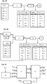
L'invention s'applique pour une installation de commande d'un moteur électrique, qui comporte :
- Un variateur de vitesse SD destiné à commander le moteur électrique M et comprenant notamment un étage onduleur INV destiné à convertir une tension continue en une tension variable à appliquer au moteur électrique M ; Le variateur de vitesse 1 est ici représenté triphasé ;
- Un transformateur TR connecté sur les phases de sortie (trois phases,
référencées - Un moteur électrique M connecté au secondaire du transformateur TR ; Le moteur électrique M peut être de tout type, synchrone ou asynchrone, le procédé de l'invention étant indépendant du type de moteur connecté.
- A variable speed drive SD for controlling the electric motor M and comprising in particular an inverter stage INV for converting a DC voltage into a variable voltage to be applied to the electric motor M; The
variable speed drive 1 is here represented three-phase; - A TR transformer connected to the output phases (three phases, referenced 1, 2, 3) of the SD drive. The transformer TR has a primary (index p) to which are connected the output phases of the variable speed drive SD and a secondary (index s);
- An electric motor M connected to the secondary of the transformer TR; The electric motor M can be of any type, synchronous or asynchronous, the method of the invention being independent of the type of connected motor.
Le variateur de vitesse SD comporte une unité de traitement et de commande UC destinée à mettre en oeuvre une loi de commande LC permettant de déterminer, en tenant compte par exemple d'une consigne de vitesse en entrée, les tensions à appliquer au moteur électrique M lors du fonctionnement normal du moteur et les ordres de commande CTL à appliquer à l'étage onduleur INV pour obtenir ces tensions de sortie.The variable speed drive SD comprises a processing and control unit UC intended to implement a control law LC making it possible to determine, taking into account, for example, an input speed setpoint, the voltages to be applied to the electric motor M during normal operation of the motor and the CTL control commands to be applied to the INV inverter stage to obtain these output voltages.
Le variateur de vitesse peut comporter un étage redresseur REC en entrée, destiné à convertir une tension alternative fournie par le réseau électrique N en une tension continue. Il peut également comporter un bus continu d'alimentation connecté d'une part à l'étage redresseur REC et d'autre part à l'étage onduleur INV. Le bus continu d'alimentation peut comporter deux lignes d'alimentation reliées entre elles par au moins un condensateur de bus Cbus configuré pour stabiliser la tension du bus.The variable speed drive may comprise an input REC rectifier stage intended to convert an AC voltage supplied by the electrical network N into a DC voltage. It may also comprise a DC supply bus connected on the one hand to the rectifier stage REC and on the other hand to the INV inverter stage. The DC supply bus may comprise two power supply lines interconnected by at least one Cbus bus capacitor configured to stabilize the bus voltage.
L'invention vise à proposer un procédé de commande permettant de déterminer au final la séquence de démarrage adaptée à l'installation. Pour cela, le procédé de commande vise notamment à mettre en oeuvre une séquence d'identification du transformateur TR qui est intercalé entre le variateur de vitesse SD et le moteur électrique M lorsque ce transformateur TR a été considéré comme nécessaire pour la mise en oeuvre de l'application.The aim of the invention is to propose a control method making it possible to finally determine the start sequence adapted to the installation. For this, the process of control aims in particular to implement a transformer identification sequence TR which is interposed between the variable speed drive SD and the electric motor M when the transformer TR has been considered necessary for the implementation of the application.
Par identification du transformateur TR, on entend la détermination du gain et/ou du déphasage généré par le transformateur TR entre le primaire et le secondaire du transformateur, en fonction de la fréquence statorique d'excitation ωst générée par le variateur de vitesse à destination du moteur électrique M placé en aval du transformateur TR. A partir des données recueillies, il sera possible de déterminer une fonction de transfert pour relier la fréquence statorique d'excitation ωst appliquée en entrée aux courants et tension présents au primaire et au secondaire du transformateur. La fonction de transfert obtenue devra ensuite être inversée pour être employée dans la séquence de démarrage. De manière générale, on pourra parler du transfert réalisé par le transformateur entre le primaire et le secondaire, ce transfert étant réalisé par l'application d'un gain et/ou d'un déphasage.By identification of the transformer TR is meant the determination of the gain and / or the phase difference generated by the transformer TR between the primary and the secondary of the transformer, as a function of the stator excitation frequency ωst generated by the variable speed drive to the electric motor M placed downstream of the transformer TR. From the collected data, it will be possible to determine a transfer function for connecting the stator excitation frequency ωst applied to the currents and voltage present at the primary and secondary of the transformer. The resulting transfer function will then have to be reversed to be used in the boot sequence. In general, we can talk about the transfer made by the transformer between the primary and secondary, this transfer being achieved by applying a gain and / or a phase shift.
Autrement dit, il s'agit de déterminer un diagramme de Bode du transformateur. De manière connue, un diagramme de Bode est un moyen de représenter le comportement fréquentiel d'un système (ici le transformateur). Il peut être utilisé pour visualiser rapidement la marge de gain et la marge de phase d'un système.In other words, it is a question of determining a Bode diagram of the transformer. In known manner, a Bode diagram is a means of representing the frequency behavior of a system (here the transformer). It can be used to quickly visualize the gain margin and phase margin of a system.
Le procédé de commande est mis en oeuvre par un système de commande adapté.The control method is implemented by a suitable control system.
Le système de commande comporte une unité de traitement et de commande qui comporte au moins un microcontrôleur. Cette unité de de traitement et de commande UC peut être celle du variateur de vitesse. Le système de commande peut inclure le variateur de vitesse.The control system comprises a processing and control unit which comprises at least one microcontroller. This CPU processing and control unit may be that of the variable speed drive. The control system may include the drive controller.
La séquence d'identification du transformateur est avantageusement mise en oeuvre en dehors du fonctionnement normal de l'installation. Elle peut être mise en oeuvre lors d'une première mise sous tension ou lors d'une étape de paramétrage particulière.The identification sequence of the transformer is advantageously implemented outside the normal operation of the installation. It can be implemented during a first power-up or during a particular parameterization step.
De manière connue, le variateur de vitesse SD, plus particulièrement son étage onduleur, est commandé pour appliquer une tension triphasée sur les trois phases de sortie, dont la fréquence et l'amplitude peuvent varier. Classiquement, la loi de commande LC se base sur un courant de référence Iref. A partir du courant de référence et des mesures ou estimations du courant, la loi de commande LC détermine la tension de référence Vref à partir de laquelle sont déterminées des tensions simples V1_ref, V2_ref, V3_ref à obtenir sur chaque phase de sortie. L'unité de traitement et de commande UC détermine ensuite les ordres de commande à appliquer aux transistors de l'étage onduleur pour obtenir les tensions souhaitées.In known manner, the variable speed drive SD, more particularly its inverter stage, is controlled to apply a three-phase voltage to the three output phases, whose frequency and amplitude may vary. Conventionally, the LC control law is based on a reference current Iref. From the reference current and current measurements or estimates, the LC control law determines the voltage reference Vref from which are determined simple voltages V1_ref, V2_ref, V3_ref to obtain on each output phase. The processing and control unit UC then determines the control commands to be applied to the transistors of the inverter stage to obtain the desired voltages.
Les tensions V1_ref, V2_ref, V3_ref sont de la forme : ![]()
![]()
![]()
![]()
![]()
![]()
Dans la suite de la description, nous expliquerons le principe de l'invention en se basant sur les modules de courant et les modules de tension, résultant respectivement des courants et des tensions sur les trois phases de l'installation. Mais il faut comprendre que le principe peut être appliqué de manière identique en se basant sur les courants et les tensions pris sur chaque phase.In the remainder of the description, we will explain the principle of the invention based on current modules and voltage modules, respectively resulting currents and voltages on the three phases of the installation. But it must be understood that the principle can be applied identically based on the currents and voltages taken on each phase.
Le système de commande comporte un module d'identification M1 du transformateur, configuré pour être exécuté par l'unité de traitement et de commande UC en vue de mettre en oeuvre la séquence d'identification.The control system comprises an identification module M1 of the transformer, configured to be executed by the processing and control unit UC in order to implement the identification sequence.
Le module d'identification M1 comporte un module M10 d'application d'un profil en fréquence, configuré pour être exécuté par l'unité de traitement et de commande UC.The identification module M1 comprises a module M10 for applying a frequency profile, configured to be executed by the processing and control unit UC.
Le profil de fréquence statorique comporte plusieurs points de fonctionnement en fréquence ωst_i distincts successifs appliqués en fonction du temps. Chaque point de fonctionnement en fréquence est défini par un indice i, avec i allant de 1 à n.The stator frequency profile comprises several successive distinct frequency operating points ωst_i applied as a function of time. Each frequency operating point is defined by an index i, with i ranging from 1 to n.
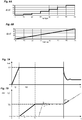
Lors de la séquence d'identification, l'amplitude de la tension déterminée par la loi de commande LC est pour sa part choisie de manière adaptée pour ne pas saturer le transformateur, ni détériorer le moteur électrique. Les points de fonctionnement en fréquence ωst_i sont avantageusement distincts, mais il n'est nullement nécessaire qu'ils suivent un profil particulier. Il faut comprendre donc que tout profil de variation de la fréquence, permettant de définir plusieurs points de fonctionnement en fréquence distincts pourrait être envisagé. A titre d'exemple, deux configurations sont présentées ci-dessous sur les
Une première configuration représentée sur la
Une deuxième configuration représentée sur la
En ce qui concerne le contrôle de la tension de sortie (résultant des trois tensions triphasées) en amplitude V, plusieurs variantes peuvent être envisagées.As regards the control of the output voltage (resulting from the three-phase voltages) in amplitude V, several variants can be envisaged.
Dans une première variante représentée sur la
Dans une deuxième variante de réalisation illustrée sur la
La séquence d'identification consiste ensuite à acquérir, pour chaque point de fonctionnement ωst_i en fréquence, le courant Ip_i et/ou la tension Vp_i au primaire du transformateur et respectivement le courant Is_i et/ou la tension Vs_i au secondaire du transformateur. Autrement dit, lorsque le courant Ip_i est acquis au primaire, le courant is_i au secondaire doit être acquis. De même, lorsque la tension Vp_i est acquise au primaire, la tension Vs_i au secondaire doit être acquise. Le système peut aussi se baser à la fois sur les courants au primaire et au secondaire et sur les tensions au primaire et au secondaire pour définir la fonction de transfert du transformateur TR mais il faut comprendre qu'une seule des grandeurs (courant ou tension) suffit. Dans la suite de la description, on parlera d'acquisition en courant et/ou tension et il faut comprendre que l'acquisition du courant et/ou de la tension au primaire du transformateur implique forcément de manière respective l'acquisition du courant et/ou de la tension au secondaire.The identification sequence then consists in acquiring, for each operating point ωst_i in frequency, the current Ip_i and / or the voltage Vp_i at the primary of the transformer and respectively the current Is_i and / or the voltage Vs_i at the secondary of the transformer. In other words, when the current Ip_i is acquired at the primary, the current is_i secondary must be acquired. Likewise, when the voltage Vp_i is acquired at the primary, the voltage Vs_i at the secondary must be acquired. The system can also be based on both the primary and secondary currents and the primary and secondary voltages to define the transfer function of the transformer TR, but only one of the quantities (current or voltage) must be understood. enough. In the remainder of the description, reference will be made to current and / or voltage acquisition and it should be understood that the acquisition of the current and / or the voltage at the primary of the transformer necessarily implies respectively the acquisition of the current and / or or secondary voltage.
Le système de commande comporte des premiers moyens d'acquisition du courant et/ou de la tension au primaire du transformateur et des seconds moyens d'acquisition du courant et/ou de la tension au secondaire du transformateur.The control system comprises first means for acquiring the current and / or voltage at the primary of the transformer and second means for acquiring the current and / or voltage at the secondary of the transformer.
Les premiers moyens d'acquisition peuvent comporter des capteurs Sp de mesure de courant et/ou de tension placés au primaire du transformateur TR.The first acquisition means may comprise current and / or voltage measuring sensors SP placed at the primary of the transformer TR.
Les seconds moyens d'acquisition peuvent comporter des capteurs Ss de mesure de courant et/ou de tension placés au secondaire du transformateur TR.The second acquisition means may comprise current and / or voltage measuring sensors Ss placed at the secondary of the transformer TR.
Les premiers moyens d'acquisition peuvent comporter un premier module d'acquisition M20 exécuté par l'unité de traitement et de commande UC pour acquérir les données de courant Ip_i et/ou les données de tension Vp_i mesurées au primaire du transformateur pour chaque point de fonctionnement en fréquence ωst_i.The first acquisition means may comprise a first acquisition module M20 executed by the processing and control unit UC to acquire the current data Ip_i and / or the voltage data Vp_i measured at the primary of the transformer for each point of frequency operation ωst_i.
Les seconds moyens d'acquisition peuvent comporter un deuxième module d'acquisition M21 exécuté par l'unité de traitement et de commande UC pour acquérir de manière respective les données de courant Is_i et/ou les données de tension Vs_i mesurées au secondaire du transformateur TR pour chaque point de fonctionnement en fréquence ωst_i.The second acquisition means may comprise a second acquisition module M21 executed by the processing and control unit UC for respectively acquiring the current data Is_i and / or the voltage data Vs_i measured at the secondary of the transformer TR for each operating point in frequency ωst_i.
Le premier module d'acquisition M20 et le deuxième module d'acquisition M21 sont connectés à chaque capteur de mesure en vue de récupérer les données de mesure de courant et/ou les données de mesure de tension.The first acquisition module M20 and the second acquisition module M21 are connected to each measurement sensor in order to retrieve the current measurement data and / or the voltage measurement data.
Le premier module d'acquisition et le deuxième module d'acquisition sont synchronisés de manière à faire coïncider à chaque instant d'acquisition, les données de courant acquises au primaire avec les données de courant acquises au secondaire du transformateur pour chaque point de fonctionnement en fréquence.The first acquisition module and the second acquisition module are synchronized so as to make the data coincide at each acquisition instant. of currents acquired at the primary with the current data acquired at the secondary of the transformer for each operating point in frequency.
Le premier module d'acquisition et le deuxième module d'acquisition sont synchronisés de manière à faire coïncider en temps, les données de tension acquises au primaire avec les données de tension acquises au secondaire du transformateur pour chaque point de fonctionnement en fréquence.The first acquisition module and the second acquisition module are synchronized so as to coincide in time the voltage data acquired at the primary with the voltage data acquired at the secondary of the transformer for each operating point in frequency.
Les premiers moyens d'acquisition peuvent être ceux déjà employés par le variateur de vitesse SD pour mettre en oeuvre sa loi de commande LC du moteur électrique.The first acquisition means may be those already used by the variable speed drive SD to implement its control law LC of the electric motor.
Les seconds moyens d'acquisition peuvent comporter une carte électronique externe connectée à l'unité de traitement et de commande UC.The second acquisition means may comprise an external electronic card connected to the processing and control unit UC.
Les capteurs de courant et/ou de tension placés au secondaire du transformateur ainsi que la carte électronique externe peuvent être employés uniquement pour la mise en oeuvre de la séquence d'identification et retirés par la suite lors du démarrage du moteur électrique et lors du fonctionnement normal de l'installation.The current and / or voltage sensors placed on the secondary of the transformer as well as the external electronic card can be used only for the implementation of the identification sequence and subsequently removed when starting the electric motor and during operation. normal installation.
Pour chaque point de fonctionnement en fréquence, le module d'identification M1 lance une étape d'acquisition des données de courant et/ou de tension par l'exécution du premier module d'acquisition M20 et du deuxième module d'acquisition M21 définis ci-dessus.For each operating point in frequency, the identification module M1 initiates a step of acquiring current and / or voltage data by executing the first acquisition module M20 and the second acquisition module M21 defined herein. -above.
A l'issue de l'étape d'acquisition, l'unité de traitement et de commande UC dispose ainsi d'une table de données mettant en correspondance chaque valeur de fréquence statorique de référence et une valeur de courant Ip_i et/ou de tension Vp_i au primaire et une valeur de courant Is_i et/ou de tension Vs_i au secondaire.At the end of the acquisition step, the processing and control unit UC thus has a data table mapping each reference stator frequency value and a current value Ip_i and / or voltage Vp_i at the primary and a current value Is_i and / or voltage Vs_i at the secondary.
A partir de ces données, l'unité de traitement et de commande UC exécute un module d'analyse M3 des données en courant et/ou en tension acquises au primaire et au secondaire pour chaque point de fonctionnement en fréquence ωst_i afin de déterminer pour chaque point de fonctionnement en fréquence un gain ki et/ou un déphasage ϕi, représentatifs d'un transfert en courant et/ou tension réalisé par le transformateur. Ces données représentent plus précisément l'inverse de la fonction de transfert (gain et/ou déphasage) du transformateur. Ces données sont enregistrées par l'unité de traitement et de commande UC dans ses moyens de mémorisation. Le principe est illustré par la
Le module d'analyse M3 est ensuite configuré pour générer un module de transfert M4 destiné à être exécuté par l'unité de traitement et de commande UC et configuré pour assurer le transfert d'un courant et/ou d'une tension à appliquer au primaire du transformateur en un courant et/ou une tension présente au secondaire, en tenant compte de la fréquence statorique et des valeurs de gain et/ou de déphasage mémorisés à l'issue de la séquence d'identification.The analysis module M3 is then configured to generate a transfer module M4 intended to be executed by the processing and control unit UC and configured to ensure the transfer of a current and / or a voltage to be applied to the primary current of the transformer in a current and / or a voltage present at the secondary, taking into account the stator frequency and the values of gain and / or phase shift stored at the end of the identification sequence.
Ce module de transfert M4 est employé pour créer une séquence de démarrage spécifique du moteur électrique. Le module de transfert peut se présenter sous différentes formes :
- Il peut s'agir d'une table de correspondance entre les différentes données, à laquelle l'unité de traitement et de commande peut se référer lors de la génération d'une séquence de démarrage d'un moteur électrique ;
- Il peut s'agir de la fonction inverse du transfert du transformateur pour l'appliquer lors de la séquence de démarrage.
- It can be a correspondence table between the different data, to which the processing and control unit can refer during the generation of a starting sequence of an electric motor;
- This may be the reverse function of the transformer transfer to apply it during the boot sequence.
Si on ne considère que le gain du transformateur, la fonction de transfert prend la forme d'une fonction G(ωst)=Gain transformateur. La fonction inverse correspondra ainsi à k=1/G(ωst).If we consider only the gain of the transformer, the transfer function takes the form of a function G (ωst) = transformer gain. The inverse function will correspond to k = 1 / G (ωst).
Le module de transfert M4 peut être exécuté :
- En ligne pendant le déroulement d'une séquence de démarrage du moteur électrique, chaque courant de référence de la trajectoire étant corrigé par le module de transfert, ou
- Hors ligne, c'est-à-dire préalablement à une séquence de démarrage du moteur électrique, pour calculer dans sa totalité une nouvelle séquence de démarrage qui sera mémorisée et employée à chaque nouveau démarrage du moteur électrique.
- Online during the course of a starting sequence of the electric motor, each reference current of the trajectory being corrected by the transfer module, or
- Offline, that is to say prior to a starting sequence of the electric motor, to calculate in its entirety a new start sequence that will be stored and used at each new start of the electric motor.
Ce module de transfert M4 permet de générer la trajectoire de courant de référence qui est adaptée pour démarrer le moteur électrique, tout en protégeant le moteur électrique et le transformateur.This transfer module M4 is used to generate the reference current path which is adapted to start the electric motor, while protecting the electric motor and the transformer.
En référence aux
Dans une première étape, la séquence de démarrage consiste à déterminer et appliquer un courant de référence Iref (module M6). Ce courant de référence Iref est choisi à une valeur supérieure à une première valeur seuil, correspondant au minimum de courant à appliquer pour faire tourner le moteur électrique synchrone, c'est-à-dire correspondant au minimum du courant de charge. La
Dans une deuxième étape, l'unité de commande UC applique une trajectoire de fréquence statorique ωst_ref (module M7). La fréquence statorique ωst_ref est choisie à une valeur la plus basse possible mais supérieure à une deuxième valeur seuil, synonyme de saturation du transformateur, comme expliqué par la démonstration ci-dessus. La
Comme lors du démarrage du moteur le rotor n'est pas aligné, la fréquence réelle du rotor ne suit pas la fréquence statorique ωst_ref (
Une fois le rotor accroché, l'unité de commande connaît la fréquence du moteur, celle-ci étant égale à la fréquence de la tension délivrée par le variateur de vitesse, ainsi qu'une estimation de l'angle θ du rotor.Once the rotor hooked, the control unit knows the frequency of the motor, which is equal to the frequency of the voltage delivered by the variable speed drive, as well as an estimate of the rotor angle θ.
L'unité de commande commute alors la commande du moteur électrique synchrone vers la loi de commande principale LC.The control unit then switches the control of the synchronous electric motor to the main control law LC.
Cette séquence de démarrage classique est mise en oeuvre en tenant compte d'un gain fixe pour le transformateur. Le module de transfert déterminé par le procédé de commande décrit ci-dessus permet de corriger cette séquence de démarrage afin de l'adapter à l'installation et notamment aux caractéristiques réelles de gain et/ou de déphasage engendrées par la présence du transformateur.This conventional start sequence is implemented taking into account a fixed gain for the transformer. The transfer module determined by the control method described above makes it possible to correct this startup sequence in order to adapt it to the installation and in particular to the actual gain and / or phase shift characteristics generated by the presence of the transformer.
Comme déjà décrit ci-dessus, cette séquence de démarrage classique peut s'avérer inefficace en cas d'inertie importante au niveau du moteur électrique.As already described above, this conventional start-up sequence can be ineffective in the event of significant inertia in the electric motor.
Le module de transfert M4 déterminé ci-dessus permet donc de corriger la séquence.The transfer module M4 determined above thus makes it possible to correct the sequence.
Les
- Recevoir en entrée chaque valeur de courant Iref de la trajectoire de courant classique ;
- Appliquer à chaque valeur de courant Iref reçue un transfert en tenant compte d'un gain ki et/ou d'un déphasage ϕi ;
- Générer (en ligne ou hors-ligne) la nouvelle trajectoire de courant de référence.
- Receive as input each current value Iref of the conventional current path;
- Apply to each received current value Iref a transfer taking into account a gain ki and / or a phase shift φi;
- Generate (online or offline) the new reference current path.
Pendant l'application de la nouvelle trajectoire de courant, la trajectoire de fréquence reste identique à celle de la séquence classique.During the application of the new current path, the frequency trajectory remains identical to that of the conventional sequence.
Sur la
Sur la
On comprend que la solution de l'invention présente de nombreux avantages, parmi lesquels :
- L'identification des caractéristiques du transformateur permet de corriger la séquence de démarrage, assurant ainsi le démarrage du moteur électrique quel que soit le niveau d'inertie ;
- La séquence d'identification est simple à mettre en oeuvre et automatique ;
- Le procédé de commande peut s'adapter à l'application connectée sur la sortie du variateur de vitesse ;
- La solution proposée évite l'ajout de capteurs supplémentaires côté moteur lors de la commande du moteur électrique ; L'ajout de capteurs supplémentaires est nécessaire uniquement lors de la séquence d'identification du transformateur.
- The identification of the characteristics of the transformer makes it possible to correct the starting sequence, thus ensuring the starting of the electric motor whatever the level of inertia;
- The identification sequence is simple to implement and automatic;
- The control method can be adapted to the application connected to the output of the drive controller;
- The proposed solution avoids the addition of additional sensors on the motor side when controlling the electric motor; The addition of additional sensors is only necessary during the transformer identification sequence.
Claims (20)
Applications Claiming Priority (1)
| Application Number | Priority Date | Filing Date | Title |
|---|---|---|---|
| FR1762421A FR3075512B1 (en) | 2017-12-19 | 2017-12-19 | METHOD FOR CONTROLLING AN ELECTRIC MOTOR INCLUDING AN IDENTIFICATION SEQUENCE OF A TRANSFORMER |
Publications (2)
| Publication Number | Publication Date |
|---|---|
| EP3503380A1 true EP3503380A1 (en) | 2019-06-26 |
| EP3503380B1 EP3503380B1 (en) | 2022-02-16 |
Family
ID=62017388
Family Applications (1)
| Application Number | Title | Priority Date | Filing Date |
|---|---|---|---|
| EP18206896.5A Active EP3503380B1 (en) | 2017-12-19 | 2018-11-19 | Method for controlling an electric motor including an identification sequence of a transformer |
Country Status (5)
| Country | Link |
|---|---|
| US (1) | US10892693B2 (en) |
| EP (1) | EP3503380B1 (en) |
| CN (1) | CN109951109A (en) |
| ES (1) | ES2908263T3 (en) |
| FR (1) | FR3075512B1 (en) |
Families Citing this family (2)
| Publication number | Priority date | Publication date | Assignee | Title |
|---|---|---|---|---|
| CN114616753A (en) * | 2019-11-05 | 2022-06-10 | 株式会社安川电机 | Power conversion device, power conversion method, and system |
| JP7423498B2 (en) * | 2020-12-03 | 2024-01-29 | 株式会社ミツバ | Motor control device, motor drive system, hydraulic pressure generator, motor control method, and motor control program |
Citations (2)
| Publication number | Priority date | Publication date | Assignee | Title |
|---|---|---|---|---|
| US20150002059A1 (en) * | 2013-06-29 | 2015-01-01 | Rockwell Automation Technologies, Inc. | Method and apparatus for stability control of open loop motor drive operation |
| EP2963802A1 (en) * | 2014-06-30 | 2016-01-06 | Schneider Toshiba Inverter Europe SAS | Control method for starting a synchronous electric motor |
Family Cites Families (7)
| Publication number | Priority date | Publication date | Assignee | Title |
|---|---|---|---|---|
| US5909098A (en) * | 1996-05-02 | 1999-06-01 | Reda Pump | Downhole pumping system with variable speed pulse-width modulated inverter coupled to electrical motor via non-gap transformer |
| US7932693B2 (en) * | 2005-07-07 | 2011-04-26 | Eaton Corporation | System and method of controlling power to a non-motor load |
| US7468595B2 (en) * | 2005-07-26 | 2008-12-23 | Eaton Corporation | System and method of controlling the start-up of an adjustable speed motor drive based sinusoidal output power conditioner |
| US7724549B2 (en) * | 2006-09-22 | 2010-05-25 | Rockwell Automation Technologies, Inc. | Integrated power conditioning system and housing for delivering operational power to a motor |
| AT506138B1 (en) * | 2007-11-22 | 2009-11-15 | Fronius Int Gmbh | METHOD FOR DETECTING THE OPERATION OF A CONTROL PANEL OF AN OPERATING FRONT AND OPERATING FRONT WITH AT LEAST ONE CONTROL ELEMENT |
| CN103729008B (en) * | 2012-10-12 | 2017-05-03 | 沈阳君印科技有限公司 | Wide-current-range alternating-current and constant-current source compensation type control method |
| US9054621B2 (en) * | 2013-04-23 | 2015-06-09 | Rockwell Automation Technologies, Inc. | Position sensorless open loop control for motor drives with output filter and transformer |
-
2017
- 2017-12-19 FR FR1762421A patent/FR3075512B1/en active Active
-
2018
- 2018-11-14 US US16/190,336 patent/US10892693B2/en active Active
- 2018-11-19 EP EP18206896.5A patent/EP3503380B1/en active Active
- 2018-11-19 ES ES18206896T patent/ES2908263T3/en active Active
- 2018-12-04 CN CN201811474171.2A patent/CN109951109A/en active Pending
Patent Citations (2)
| Publication number | Priority date | Publication date | Assignee | Title |
|---|---|---|---|---|
| US20150002059A1 (en) * | 2013-06-29 | 2015-01-01 | Rockwell Automation Technologies, Inc. | Method and apparatus for stability control of open loop motor drive operation |
| EP2963802A1 (en) * | 2014-06-30 | 2016-01-06 | Schneider Toshiba Inverter Europe SAS | Control method for starting a synchronous electric motor |
Also Published As
| Publication number | Publication date |
|---|---|
| US20190190414A1 (en) | 2019-06-20 |
| US10892693B2 (en) | 2021-01-12 |
| FR3075512B1 (en) | 2019-11-08 |
| ES2908263T3 (en) | 2022-04-28 |
| EP3503380B1 (en) | 2022-02-16 |
| CN109951109A (en) | 2019-06-28 |
| FR3075512A1 (en) | 2019-06-21 |
Similar Documents
| Publication | Publication Date | Title |
|---|---|---|
| EP2684289B1 (en) | Control method implemented in a power converter and intended for identifying parameters linked to the magnetic saturation of an electric motor | |
| EP2003461B1 (en) | Method for detecting the loss of one or more phases in a permanent-magnet synchronous electric motor | |
| EP1881594B1 (en) | Method of adjusting parameters of a synchronous motor and variable speed drive using such a method | |
| EP2246973A2 (en) | Method for determining the position of the flux vector of a motor | |
| EP3451525B1 (en) | Method for identifying magnetic saturation parameters of an asynchronous electric motor | |
| EP3503380B1 (en) | Method for controlling an electric motor including an identification sequence of a transformer | |
| EP3069441B1 (en) | Method and system for controlling an automotive vehicle three-phase electric machine supplied via chopped voltages | |
| FR2988234A1 (en) | METHOD FOR NON-CONTACT LOADING OF A BATTERY OF AN ELECTRIC MOTOR VEHICLE | |
| EP3229366A1 (en) | Method for controlling an asynchronous electrical motor | |
| EP3401694B1 (en) | Method for identifying the electrical resistance of the rotor of an electric motor | |
| EP2963802B1 (en) | Control method for starting a synchronous electric motor | |
| EP3287795A1 (en) | Method for determining the frequency of an ac signal | |
| EP2780771B1 (en) | Control method and system for correcting the voltages to be applied to an electrical load | |
| FR3071681B1 (en) | CONTROL METHOD FOR VERIFYING COMPATIBILITY BETWEEN A SPEED DRIVE AND INPUT FILTER | |
| EP3166220B1 (en) | Dynamic limiting device and method for dynamic limiting by such a device | |
| EP3709504A1 (en) | Detection of the type of an electric motor for configuring a speed variator | |
| EP3128667B1 (en) | Control method for starting a synchronous electric motor | |
| EP2803135A2 (en) | Method of control implemented for controlling two permanent-magnet synchronous electric motors connected in parallel | |
| WO2015121049A2 (en) | Method of controlling a permanent-magnet electric machine optimizing the joule losses | |
| FR3024616A1 (en) | METHOD AND DEVICE FOR CONTROLLING THE ELECTROMAGNETIC TORQUE OF A MOTORPROOF GROUP | |
| FR3029366A1 (en) | DEVICE AND METHOD FOR CONTROLLING THE TORQUE OF A VARIABLE RELUCTANCE ELECTRIC MACHINE |
Legal Events
| Date | Code | Title | Description |
|---|---|---|---|
| PUAI | Public reference made under article 153(3) epc to a published international application that has entered the european phase |
Free format text: ORIGINAL CODE: 0009012 |
|
| STAA | Information on the status of an ep patent application or granted ep patent |
Free format text: STATUS: THE APPLICATION HAS BEEN PUBLISHED |
|
| AK | Designated contracting states |
Kind code of ref document: A1 Designated state(s): AL AT BE BG CH CY CZ DE DK EE ES FI FR GB GR HR HU IE IS IT LI LT LU LV MC MK MT NL NO PL PT RO RS SE SI SK SM TR |
|
| AX | Request for extension of the european patent |
Extension state: BA ME |
|
| STAA | Information on the status of an ep patent application or granted ep patent |
Free format text: STATUS: REQUEST FOR EXAMINATION WAS MADE |
|
| 17P | Request for examination filed |
Effective date: 20191128 |
|
| RBV | Designated contracting states (corrected) |
Designated state(s): AL AT BE BG CH CY CZ DE DK EE ES FI FR GB GR HR HU IE IS IT LI LT LU LV MC MK MT NL NO PL PT RO RS SE SI SK SM TR |
|
| STAA | Information on the status of an ep patent application or granted ep patent |
Free format text: STATUS: EXAMINATION IS IN PROGRESS |
|
| 17Q | First examination report despatched |
Effective date: 20200507 |
|
| STAA | Information on the status of an ep patent application or granted ep patent |
Free format text: STATUS: EXAMINATION IS IN PROGRESS |
|
| GRAP | Despatch of communication of intention to grant a patent |
Free format text: ORIGINAL CODE: EPIDOSNIGR1 |
|
| STAA | Information on the status of an ep patent application or granted ep patent |
Free format text: STATUS: GRANT OF PATENT IS INTENDED |
|
| INTG | Intention to grant announced |
Effective date: 20211125 |
|
| GRAS | Grant fee paid |
Free format text: ORIGINAL CODE: EPIDOSNIGR3 |
|
| GRAA | (expected) grant |
Free format text: ORIGINAL CODE: 0009210 |
|
| STAA | Information on the status of an ep patent application or granted ep patent |
Free format text: STATUS: THE PATENT HAS BEEN GRANTED |
|
| AK | Designated contracting states |
Kind code of ref document: B1 Designated state(s): AL AT BE BG CH CY CZ DE DK EE ES FI FR GB GR HR HU IE IS IT LI LT LU LV MC MK MT NL NO PL PT RO RS SE SI SK SM TR |
|
| REG | Reference to a national code |
Ref country code: GB Ref legal event code: FG4D Free format text: NOT ENGLISH |
|
| REG | Reference to a national code |
Ref country code: CH Ref legal event code: EP |
|
| REG | Reference to a national code |
Ref country code: DE Ref legal event code: R096 Ref document number: 602018030863 Country of ref document: DE |
|
| REG | Reference to a national code |
Ref country code: AT Ref legal event code: REF Ref document number: 1469514 Country of ref document: AT Kind code of ref document: T Effective date: 20220315 |
|
| REG | Reference to a national code |
Ref country code: IE Ref legal event code: FG4D Free format text: LANGUAGE OF EP DOCUMENT: FRENCH |
|
| REG | Reference to a national code |
Ref country code: ES Ref legal event code: FG2A Ref document number: 2908263 Country of ref document: ES Kind code of ref document: T3 Effective date: 20220428 |
|
| REG | Reference to a national code |
Ref country code: LT Ref legal event code: MG9D |
|
| REG | Reference to a national code |
Ref country code: NL Ref legal event code: MP Effective date: 20220216 |
|
| REG | Reference to a national code |
Ref country code: AT Ref legal event code: MK05 Ref document number: 1469514 Country of ref document: AT Kind code of ref document: T Effective date: 20220216 |
|
| PG25 | Lapsed in a contracting state [announced via postgrant information from national office to epo] |
Ref country code: SE Free format text: LAPSE BECAUSE OF FAILURE TO SUBMIT A TRANSLATION OF THE DESCRIPTION OR TO PAY THE FEE WITHIN THE PRESCRIBED TIME-LIMIT Effective date: 20220216 Ref country code: RS Free format text: LAPSE BECAUSE OF FAILURE TO SUBMIT A TRANSLATION OF THE DESCRIPTION OR TO PAY THE FEE WITHIN THE PRESCRIBED TIME-LIMIT Effective date: 20220216 Ref country code: PT Free format text: LAPSE BECAUSE OF FAILURE TO SUBMIT A TRANSLATION OF THE DESCRIPTION OR TO PAY THE FEE WITHIN THE PRESCRIBED TIME-LIMIT Effective date: 20220616 Ref country code: NO Free format text: LAPSE BECAUSE OF FAILURE TO SUBMIT A TRANSLATION OF THE DESCRIPTION OR TO PAY THE FEE WITHIN THE PRESCRIBED TIME-LIMIT Effective date: 20220516 Ref country code: NL Free format text: LAPSE BECAUSE OF FAILURE TO SUBMIT A TRANSLATION OF THE DESCRIPTION OR TO PAY THE FEE WITHIN THE PRESCRIBED TIME-LIMIT Effective date: 20220216 Ref country code: LT Free format text: LAPSE BECAUSE OF FAILURE TO SUBMIT A TRANSLATION OF THE DESCRIPTION OR TO PAY THE FEE WITHIN THE PRESCRIBED TIME-LIMIT Effective date: 20220216 Ref country code: HR Free format text: LAPSE BECAUSE OF FAILURE TO SUBMIT A TRANSLATION OF THE DESCRIPTION OR TO PAY THE FEE WITHIN THE PRESCRIBED TIME-LIMIT Effective date: 20220216 Ref country code: BG Free format text: LAPSE BECAUSE OF FAILURE TO SUBMIT A TRANSLATION OF THE DESCRIPTION OR TO PAY THE FEE WITHIN THE PRESCRIBED TIME-LIMIT Effective date: 20220516 |
|
| PG25 | Lapsed in a contracting state [announced via postgrant information from national office to epo] |
Ref country code: PL Free format text: LAPSE BECAUSE OF FAILURE TO SUBMIT A TRANSLATION OF THE DESCRIPTION OR TO PAY THE FEE WITHIN THE PRESCRIBED TIME-LIMIT Effective date: 20220216 Ref country code: LV Free format text: LAPSE BECAUSE OF FAILURE TO SUBMIT A TRANSLATION OF THE DESCRIPTION OR TO PAY THE FEE WITHIN THE PRESCRIBED TIME-LIMIT Effective date: 20220216 Ref country code: GR Free format text: LAPSE BECAUSE OF FAILURE TO SUBMIT A TRANSLATION OF THE DESCRIPTION OR TO PAY THE FEE WITHIN THE PRESCRIBED TIME-LIMIT Effective date: 20220517 Ref country code: FI Free format text: LAPSE BECAUSE OF FAILURE TO SUBMIT A TRANSLATION OF THE DESCRIPTION OR TO PAY THE FEE WITHIN THE PRESCRIBED TIME-LIMIT Effective date: 20220216 Ref country code: AT Free format text: LAPSE BECAUSE OF FAILURE TO SUBMIT A TRANSLATION OF THE DESCRIPTION OR TO PAY THE FEE WITHIN THE PRESCRIBED TIME-LIMIT Effective date: 20220216 |
|
| PG25 | Lapsed in a contracting state [announced via postgrant information from national office to epo] |
Ref country code: IS Free format text: LAPSE BECAUSE OF FAILURE TO SUBMIT A TRANSLATION OF THE DESCRIPTION OR TO PAY THE FEE WITHIN THE PRESCRIBED TIME-LIMIT Effective date: 20220617 |
|
| PG25 | Lapsed in a contracting state [announced via postgrant information from national office to epo] |
Ref country code: SM Free format text: LAPSE BECAUSE OF FAILURE TO SUBMIT A TRANSLATION OF THE DESCRIPTION OR TO PAY THE FEE WITHIN THE PRESCRIBED TIME-LIMIT Effective date: 20220216 Ref country code: SK Free format text: LAPSE BECAUSE OF FAILURE TO SUBMIT A TRANSLATION OF THE DESCRIPTION OR TO PAY THE FEE WITHIN THE PRESCRIBED TIME-LIMIT Effective date: 20220216 Ref country code: RO Free format text: LAPSE BECAUSE OF FAILURE TO SUBMIT A TRANSLATION OF THE DESCRIPTION OR TO PAY THE FEE WITHIN THE PRESCRIBED TIME-LIMIT Effective date: 20220216 Ref country code: EE Free format text: LAPSE BECAUSE OF FAILURE TO SUBMIT A TRANSLATION OF THE DESCRIPTION OR TO PAY THE FEE WITHIN THE PRESCRIBED TIME-LIMIT Effective date: 20220216 Ref country code: DK Free format text: LAPSE BECAUSE OF FAILURE TO SUBMIT A TRANSLATION OF THE DESCRIPTION OR TO PAY THE FEE WITHIN THE PRESCRIBED TIME-LIMIT Effective date: 20220216 Ref country code: CZ Free format text: LAPSE BECAUSE OF FAILURE TO SUBMIT A TRANSLATION OF THE DESCRIPTION OR TO PAY THE FEE WITHIN THE PRESCRIBED TIME-LIMIT Effective date: 20220216 |
|
| REG | Reference to a national code |
Ref country code: DE Ref legal event code: R097 Ref document number: 602018030863 Country of ref document: DE |
|
| PG25 | Lapsed in a contracting state [announced via postgrant information from national office to epo] |
Ref country code: AL Free format text: LAPSE BECAUSE OF FAILURE TO SUBMIT A TRANSLATION OF THE DESCRIPTION OR TO PAY THE FEE WITHIN THE PRESCRIBED TIME-LIMIT Effective date: 20220216 |
|
| PLBE | No opposition filed within time limit |
Free format text: ORIGINAL CODE: 0009261 |
|
| STAA | Information on the status of an ep patent application or granted ep patent |
Free format text: STATUS: NO OPPOSITION FILED WITHIN TIME LIMIT |
|
| 26N | No opposition filed |
Effective date: 20221117 |
|
| PG25 | Lapsed in a contracting state [announced via postgrant information from national office to epo] |
Ref country code: SI Free format text: LAPSE BECAUSE OF FAILURE TO SUBMIT A TRANSLATION OF THE DESCRIPTION OR TO PAY THE FEE WITHIN THE PRESCRIBED TIME-LIMIT Effective date: 20220216 |
|
| PG25 | Lapsed in a contracting state [announced via postgrant information from national office to epo] |
Ref country code: MC Free format text: LAPSE BECAUSE OF FAILURE TO SUBMIT A TRANSLATION OF THE DESCRIPTION OR TO PAY THE FEE WITHIN THE PRESCRIBED TIME-LIMIT Effective date: 20220216 |
|
| REG | Reference to a national code |
Ref country code: CH Ref legal event code: PL |
|
| REG | Reference to a national code |
Ref country code: BE Ref legal event code: MM Effective date: 20221130 |
|
| PG25 | Lapsed in a contracting state [announced via postgrant information from national office to epo] |
Ref country code: LI Free format text: LAPSE BECAUSE OF NON-PAYMENT OF DUE FEES Effective date: 20221130 Ref country code: CH Free format text: LAPSE BECAUSE OF NON-PAYMENT OF DUE FEES Effective date: 20221130 |
|
| PG25 | Lapsed in a contracting state [announced via postgrant information from national office to epo] |
Ref country code: LU Free format text: LAPSE BECAUSE OF NON-PAYMENT OF DUE FEES Effective date: 20221119 |
|
| PG25 | Lapsed in a contracting state [announced via postgrant information from national office to epo] |
Ref country code: IE Free format text: LAPSE BECAUSE OF NON-PAYMENT OF DUE FEES Effective date: 20221119 |
|
| PG25 | Lapsed in a contracting state [announced via postgrant information from national office to epo] |
Ref country code: BE Free format text: LAPSE BECAUSE OF NON-PAYMENT OF DUE FEES Effective date: 20221130 |
|
| PGFP | Annual fee paid to national office [announced via postgrant information from national office to epo] |
Ref country code: GB Payment date: 20231121 Year of fee payment: 6 |
|
| PGFP | Annual fee paid to national office [announced via postgrant information from national office to epo] |
Ref country code: ES Payment date: 20231218 Year of fee payment: 6 |
|
| PGFP | Annual fee paid to national office [announced via postgrant information from national office to epo] |
Ref country code: IT Payment date: 20231124 Year of fee payment: 6 Ref country code: FR Payment date: 20231123 Year of fee payment: 6 Ref country code: DE Payment date: 20231127 Year of fee payment: 6 |
|
| PG25 | Lapsed in a contracting state [announced via postgrant information from national office to epo] |
Ref country code: HU Free format text: LAPSE BECAUSE OF FAILURE TO SUBMIT A TRANSLATION OF THE DESCRIPTION OR TO PAY THE FEE WITHIN THE PRESCRIBED TIME-LIMIT; INVALID AB INITIO Effective date: 20181119 |
|
| PG25 | Lapsed in a contracting state [announced via postgrant information from national office to epo] |
Ref country code: CY Free format text: LAPSE BECAUSE OF FAILURE TO SUBMIT A TRANSLATION OF THE DESCRIPTION OR TO PAY THE FEE WITHIN THE PRESCRIBED TIME-LIMIT Effective date: 20220216 |