EP3503329A1 - Supraleitfähiges kabelsystem und verfahren zum kühlen des supraleitfähigen kabelsystems - Google Patents
Supraleitfähiges kabelsystem und verfahren zum kühlen des supraleitfähigen kabelsystems Download PDFInfo
- Publication number
- EP3503329A1 EP3503329A1 EP17306827.1A EP17306827A EP3503329A1 EP 3503329 A1 EP3503329 A1 EP 3503329A1 EP 17306827 A EP17306827 A EP 17306827A EP 3503329 A1 EP3503329 A1 EP 3503329A1
- Authority
- EP
- European Patent Office
- Prior art keywords
- cable
- coolant
- superconducting
- cooling
- superconducting cable
- Prior art date
- Legal status (The legal status is an assumption and is not a legal conclusion. Google has not performed a legal analysis and makes no representation as to the accuracy of the status listed.)
- Granted
Links
Images


Classifications
-
- H—ELECTRICITY
- H02—GENERATION; CONVERSION OR DISTRIBUTION OF ELECTRIC POWER
- H02G—INSTALLATION OF ELECTRIC CABLES OR LINES, OR OF COMBINED OPTICAL AND ELECTRIC CABLES OR LINES
- H02G15/00—Cable fittings
- H02G15/34—Cable fittings for cryogenic cables
-
- H—ELECTRICITY
- H01—ELECTRIC ELEMENTS
- H01B—CABLES; CONDUCTORS; INSULATORS; SELECTION OF MATERIALS FOR THEIR CONDUCTIVE, INSULATING OR DIELECTRIC PROPERTIES
- H01B12/00—Superconductive or hyperconductive conductors, cables, or transmission lines
- H01B12/16—Superconductive or hyperconductive conductors, cables, or transmission lines characterised by cooling
-
- Y—GENERAL TAGGING OF NEW TECHNOLOGICAL DEVELOPMENTS; GENERAL TAGGING OF CROSS-SECTIONAL TECHNOLOGIES SPANNING OVER SEVERAL SECTIONS OF THE IPC; TECHNICAL SUBJECTS COVERED BY FORMER USPC CROSS-REFERENCE ART COLLECTIONS [XRACs] AND DIGESTS
- Y02—TECHNOLOGIES OR APPLICATIONS FOR MITIGATION OR ADAPTATION AGAINST CLIMATE CHANGE
- Y02E—REDUCTION OF GREENHOUSE GAS [GHG] EMISSIONS, RELATED TO ENERGY GENERATION, TRANSMISSION OR DISTRIBUTION
- Y02E40/00—Technologies for an efficient electrical power generation, transmission or distribution
- Y02E40/60—Superconducting electric elements or equipment; Power systems integrating superconducting elements or equipment
Definitions
- the invention relates to a superconducting cable system and method for cooling the superconducting cable system.
- the ceramic materials which fulfill the mentioned properties include in particular YBCO (yttrium-barium-copper-oxide) having a transition temperature of 92 K.
- Another of these superconducting materials is, for example, BSCCO (bismuth-strontium-calcium-copper-oxide) a transition temperature of 110 K.
- Coolants suitable for the abovementioned superconducting materials are, for example, nitrogen, helium, neon and hydrogen or mixtures of these substances.
- a superconducting cable in today's technology has electrical conductors made of a composite material containing ceramic material at sufficiently low temperatures goes into the superconducting state.
- the electrical DC resistance of a correspondingly constructed conductor is zero with sufficient cooling, as long as a certain current and a certain magnetic field strength are not exceeded.
- the superconductive conductor is surrounded by a cable cryostat containing the coolant, in particular liquid nitrogen, and largely suppressing the radiation of ambient heat to the coolant and the superconducting cable.
- the superconducting conductor Prior to commissioning a superconducting cable or cable system having multiple superconducting cables, the superconducting conductor must be cooled to temperatures below the corresponding critical temperature.
- a method is known in which a coolant is first introduced in one direction at one end of the cable cryostat and discharged into the environment at the other end of the cable cryostat.
- cold gaseous nitrogen is used as the coolant, the temperature of which is gradually lowered, until finally liquid nitrogen enters the first end of the cable cryostat.
- the cooling system is connected to a cryogenic tank, which provides a supply of liquid nitrogen.
- gaseous nitrogen is produced by means of an evaporator from the liquid nitrogen.
- the present invention has the object to propose an improved method to a superconducting cable or a superconducting cable system to prepare for normal operation to cool and keep in normal operation at the operating temperature.
- the inventive method has the advantage that in the cable system, no evaporator means for the coolant is more needed because the refrigerant evaporates during the cooling process, first in the return line, which is insensitive to large temperature fluctuations. Temperature-sensitive components, for example, in the end caps are arranged, however, are not exposed to temperature shocks, because the coolant, in particular the liquid nitrogen, evaporates in the return line, so that at the beginning of the cooling process only gaseous nitrogen reaches the end closures. By means of the gaseous nitrogen, the terminations are cooled to ever lower temperatures until they finally reach temperatures which correspond or at least come close to the temperature of the liquid coolant. Finally, when liquid nitrogen meets the terminations as a coolant, no temperature shock occurs.
- the cooling system may be designed so that vaporized coolant is released to the environment.
- the reversal of the coolant flow direction takes place when the cable is completely filled with liquid nitrogen.
- the invention proposes a superconducting cable system with a plurality of superconducting cables, each disposed within a cryostat.
- the cryostat has a thermally insulated tube which encloses the superconducting cable and a cavity.
- a cooling system is provided, which emits a coolant, which flows through the cryostat of the superconducting cable and cools the superconducting cable to a temperature below the transition temperature.
- a return line returns the coolant that has passed through the superconducting cables to the cooling system.
- each superconducting cable has at each of its ends an end closure comprising a valve to release, lock and / or divert flow paths in the superconducting cable system.
- the valve may be designed as a directional control valve.
- the directional valves have the advantage that individual cables can be separated from the coolant circuit. This is particularly advantageous when a defect has occurred on a single superconductive cable.
- the directional valves allow the other superconducting cables to continue to operate.
- the directional valves allow it moreover, to switch the coolant streams so that in the cable system, the method according to the first aspect of the invention is executable. By means of the directional valves, it is therefore possible to warm up a defective superconducting cable and / or the return line.
- the cooling system is adapted to cause a flow of the coolant in two opposite directions.
- This feature of the refrigeration system is particularly useful because it allows a normal mode and a cooling mode to be realized in the superconducting cable system.
- sensors are arranged on the end caps, which detect the temperature of the coolant. By means of the sensors it is possible to decide whether the end caps have cooled down sufficiently to switch from the cooling mode to the normal mode. This monitoring of the temperature is advantageous in order to avoid that a thermal shock causes damage to or in one of the end closures of the cable system.
- the cooling system has a control device which receives the sensor signals and controls the flow direction of the coolant accordingly. If liquid nitrogen is detected by temperature measurement during the cooling process at an end closure, the flow direction is reversed to go from the cooling mode to the normal mode. In principle, it is also possible that an operator switches the flow direction manually.
- the return line can be isolated by means of shut-off valves of a coolant circuit.
- the presence of one or more shut-off valve (s) allows the return line and / or one of the cables to be heated while one or more superconducting cables of the cable system continue to remain cooled.
- FIG. 1 3 shows a purely schematic illustration of a superconducting cable 100 which has an end closure 101, 102 at its ends. Between the end closures 101, 102 extends a cable cryostat 103, which is also referred to as a cryostat for a short time.
- the cryostat 103 encloses at least one superconductive cable core.
- the superconducting cable 100 consisting of cryostat and cable core is in FIG. 2 shown in greater detail.
- the terminations 101, 102 enable the connection of superconducting cables to conventional medium voltage or high voltage engineering and also serve to cope with the temperature jump between the nitrogen cooled superconducting cable and components in contact with it and the environment.
- a sleeve is provided, which forms a connection point to a further superconducting cable 100. In this way, it is possible to extend the superconducting cable 100.
- FIG. 2 shows by way of example the structure of the superconducting cable 100.
- a hollow shaped body 200 which encloses a cavity 201
- superconductive tapes are arranged, which form a superconductive layer 202.
- the superconductive layer 202 is surrounded by a band-shaped semiconductive conductor smoothing 203.
- a dielectric 204 is arranged, which is surrounded by an electrically conductive screen 206, which is formed, for example, from copper wires or copper tapes or also from superconducting tapes.
- a further semiconductive layer (not shown) is arranged.
- the semiconductive layers serve to smooth the electric field in the cable by creating round surfaces and eliminating edges.
- the components mentioned are arranged in a cavity 207 which is enclosed by an inner cryostat tube 208.
- the coolant used for cooling flows in the cavity 207.
- the outside of the inner cryostat tube 208 is surrounded by a superinsulation 209, which in turn is enclosed by an outer cryostat tube 211.
- the space between the inner cryostat tube 208 and the outer cryostat tube 211 is evacuated and forms a vacuum insulation between the inner cryostat tube 208 and the outer cryostat tube 211.
- spacers (not shown) are provided in addition to the superinsulation 209, which prevent them from becoming lodged touch the cryostat tubes 208, 211.
- the cryostat tubes 208, 211 are preferably made of stainless steel.
- the cryostat tubes 208 are curved transversely to their longitudinal direction or helically.
- the outer cryostat tube 211 is surrounded by a sheath made, for example, of polyethylene (PE) or (PVC).
- FIG. 3 shows a superconducting cable system 300 with three superconducting cables 302, 303 and 304.
- the superconducting cables 302, 303 and 304 are constructed, for example, as in FIG FIG. 2
- Each of the superconducting cables 302, 303, 304 is provided at its first end with an end closure 306 and at its second end with an end closure 307.
- a refrigeration system 308 is connected to each of the end closures 306 via a coolant supply line 309.
- the end closures 307 are connected to the cooling system 308 via a return line 311 for coolant.
- a coolant supply tank 312, which is advantageously designed as a cryotank, is connected to the cooling system 308 via a feed line 313.
- the feed line 309, the return line 311 and the feed line 313 are preferably designed as cryogenic lines, ie as double-walled vacuum-insulated lines.
- liquid nitrogen is delivered by the refrigeration system 308 via the supply line 309 to the end closure 306, from where it enters the superconductive cables 302-304 and cools the superconductors.
- the coolant exits the cryostat again and is collected via the return line 311 and returned to the cooling system 308.
- the flow direction of the liquid nitrogen is in FIG. 3 indicated by arrows 314.
- the liquid nitrogen used as a coolant absorbs heat that radiates from the environment to the cable system 300 and the associated facilities. This heat is removed by the coolant and withdrawn by means of the cooling system 308 the coolant again.
- Supply line 309, superconducting cables 302-304, return line 311 and cooling system 308 form a cooling circuit. Basically, the cooling circuit is a closed circuit.
- FIG. 4 shows the fluidic circuit options of the cable system FIG. 3 in greater detail.
- the cavities 201 and 207 in which coolant may flow during operation, are shown as separate conduits that are in FIG. 4 are shown as a line.
- each cavity 207 is shown as outer conductor 401 and each inner cavity 201 as inner conductor 402.
- the supply line 309 is likewise constructed from two separate lines 403 and 404, which are designed, for example, as coaxial lines in a common cryostat or as separate lines.
- the end closures 306, 307 are designed as directional control valves which serve to connect, block or divert the path of the coolant through the cable system, in particular through individual fluid or coolant lines, which will be explained below.
- the return line 311 is designed as a single pipeline, which can be separated from the coolant circuit by means of shut-off valves 406a, 406b.
- the cable system 300 described so far can be through numerous fluidic interconnections numerous operating modes of the cable system 300 to.
- An important first operating mode is the parallel operation of the outer and inner conductors 401, 402 in each cable 302-304, in which flows through outer and inner conductors 401, 402, the coolant, in particular liquid nitrogen in the flow.
- the coolant is returned to the refrigeration system 308 through the return line 311.
- This mode of operation has the highest cooling capacity, so that the cable system 300 reaches the lowest operating temperature and consequently the has the largest current carrying capacity.
- cable system 300 also allows other modes of operation that do not require the use of return 311. These operating modes are particularly advantageous when a defect occurs at the return line 311 or one of the superconducting cables 302-304.
- a second mode of operation is described for the sake of simplicity using the example of a single superconducting cable, because in this mode of operation of a cable system with multiple superconducting cables all cables are operated in the same way.
- the coolant in the outer conductor 401 flows in advance through the superconducting cable, and the inner conductor 402 forms a return in which the refrigerant is returned.
- the connection required between the outer conductor 401 and the inner conductor 402 is produced by means of the end closure 307 and a connecting line 407.
- the line 403 forms the flow from the cooling system 308 and the line 404, the return line to the cooling system 308th
- the outer conductor 401 in all cables is connected in parallel under the inner conductor 402.
- the superconducting cables 302 and 303 form the lead, while the cable 304 forms the return.
- the cables 302-304 can also be used with reversed rollers.
- the line 403 forms the flow from the cooling system 308 and the line 404, the return line to the cooling system 308. More generally, it is provided in the third mode, that a group of superconducting cables of the cable system 300, a flow line for the Coolant while another group of superconducting cable forms a return line.
- a fourth mode is used in a cable system in which the superconducting cables used have only a single cooling channel.
- the cable system is configured so that the coolant from the cooling system can be circulated through two cables and the third cable and the return line can be warmed up.
- the liquid nitrogen circulates through the return line and one the cable while the other two cables are being warmed up.
- the principle of operation differs from the representation in FIG. 4 only in that, for example, the lines 401 in each of the cables 302-304 are omitted.
- the cooling system 308 is now controlled so that liquid nitrogen is pumped into the return line. Since the return line is at ambient temperature, the nitrogen evaporates at least in an initial phase as it enters the return line 311. The resulting gaseous nitrogen flows through the return line through the end caps 307, thereby gradually cooling the end caps and the superconducting cables 302-304. As a result of the inflowing liquid nitrogen, the return line is continuously cooled down continuously so that the liquid nitrogen in the return line continues to advance in the direction of the end closures 307.
- the end closures 307 and the superconductive cables 302-304 are already cooled by the nitrogen gas to such a low temperature that it does not cause any Thermal shock occurs when the liquid nitrogen comes into contact with the end caps 307.
- the cooling process can now be continued for a while, for example, until 306 liquid nitrogen arrives at the end caps, which is detectable for example with a temperature sensor or by means of a sample opening, possibly from the liquid nitrogen flows out.
- the superconducting cables 302-304 are then completely filled with liquid nitrogen.
- the directional control valve in the refrigeration system 308 is switched and the refrigerant flows in the direction through the cable system indicated by the arrows 314 in FIG FIG. 3 are shown. The switching of the directional valve can be done manually.
- the inventive method for cooling the cable system has the advantage that no evaporator for liquid nitrogen as in conventional superconducting cable systems is necessary.
- the directional valves in the end closures allow a defective superconducting cable to be insulated from the other superconducting cables and to heat up this cable.
- FIG. 4 For example, with three superconducting cable system 300 shown, it is possible to continue operating the cables 303 and 304 according to the second mode of operation when a defect occurs in the cable 302.
- the cable 302 and the return line 311 are in this case separated from the cooling circuit and gradually warm up. After a sufficient waiting time, the defect can be repaired. At the same time it is possible to maintain a circulation of the liquid nitrogen through the two remaining cables, so that the operation of the cable system can be continued during the repair, albeit with a lower transmission capacity.
- the cooling method described is applied again.
- FIG. 6 The essential steps of the method according to the invention for cooling a superconducting cable system are illustrated in a flow chart.
- the liquid cooling medium in particular liquid nitrogen
- the liquid nitrogen absorbs heat evaporated.
- the gaseous nitrogen thus forming spreads along the return line in the cable system.
- the gaseous nitrogen is passed through at least one superconductive cable.
- the superconducting cable is cooled by the gaseous nitrogen, with the temperature gradually decreasing over time.
- a third step S3 the refrigerant flow direction in the superconducting cable system is reversed.
- the inventive method has the advantage that in the cable system, no evaporator means for the coolant is more needed because the refrigerant evaporates during the cooling process, first in the return line, which is insensitive to large temperature fluctuations. Temperature-sensitive components, which are arranged, for example, in the end closures 306, 307, are nevertheless not exposed to temperature shocks because the coolant, in particular the liquid nitrogen, evaporates in the return line, so that initially only gaseous nitrogen reaches the end closures.
- coolant Even if liquid nitrogen is always mentioned in the description as the coolant, the invention is not restricted to this coolant but can also be used for other coolants.
- the cooling system 308 is equipped with a reversible pump to reverse the flow direction of the coolant.
Landscapes
- Superconductors And Manufacturing Methods Therefor (AREA)
- Containers, Films, And Cooling For Superconductive Devices (AREA)
Abstract
Description
- Die Erfindung betrifft ein supraleitfähiges Kabelsystem und Verfahren zum Kühlen des supraleitfähigen Kabelsystems.
- Supraleitfähiges Material hat unter anderem die Eigenschaft, dass sein elektrischer Widerstand auf Null sinkt, wenn es auf Temperaturen unterhalb der sogenannten Sprungtemperatur abgekühlt wird. Bei der Sprungtemperatur geht es in den sogenannten supraleitenden Zustand über. Der supraleitende Zustand existiert so lange wie die Temperatur T, die Stromstärke I und das magnetische Feld B unter entsprechenden kritischen Werten bleiben, die individuell von dem jeweiligen supraleitfähigen Material abhängen. Bevor im Jahr 1986 keramische Supraleiter entdeckt wurden, waren nur metallische Supraleiter bekannt. Unter den keramischen Supraleitern sind vor allem diejenigen Verbindungen von praktischer Bedeutung, deren Sprungtemperatur oberhalb der Temperatur von flüssigem Stickstoff liegt, die 77 K beträgt. Dieser Wert ist deshalb von besonderer Bedeutung, weil flüssiger Stickstoff ein vergleichsweise kostengünstiges Kühlmittel darstellt. Geeignete keramische Materialien sind beispielsweise mit seltenen Erden dotierte Materialien, die unter der Bezeichnung ReBCO (Rare-Earth-Barium-Kupfer-Oxid) bekannt geworden sind. Zu den keramischen Materialien, welche die genannten Eigenschaften erfüllen, gehört insbesondere YBCO (Yttrium-Barium-Kupfer-Oxid) mit einer Sprungtemperatur von 92 K. Ein anderes dieser supraleitfähigen Materialien ist beispielsweise BSCCO (Wismut-Strontium-Kalzium-Kupfer-Oxid) mit einer Sprungtemperatur von 110 K. Für die genannten supraleitfähigen Materialien geeignete Kühlmittel sind beispielsweise Stickstoff, Helium, Neon und Wasserstoff oder Gemische dieser Stoffe.
- Ein supraleitfähiges Kabel hat in heutiger Technik elektrische Leiter aus einem Verbundwerkstoff, welcher keramisches Material enthält, das bei ausreichend tiefen Temperaturen in den supraleitenden Zustand übergeht. Der elektrische Gleichstromwiderstand eines entsprechend aufgebauten Leiters ist bei ausreichender Kühlung Null, solange eine bestimmte Stromstärke und eine bestimmte Magnetfeldstärke nicht überschritten werden. Um die erforderlichen niedrigeren Temperaturen zu erreichen, ist der supraleitfähige Leiter von einem Kabelkryostaten umgeben, der das Kühlmittel, insbesondere flüssigen Stickstoff, enthält und die Einstrahlung von Umgebungswärme auf das Kühlmittel und das supraleitfähige Kabel weitgehend unterbindet.
- Vor der Inbetriebnahme eines supraleitfähigen Kabels oder eines Kabelsystems, das mehrere supraleitfähige Kabel aufweist, muss der supraleitfähige Leiter auf Temperaturen unterhalb der entsprechenden Sprungtemperatur abgekühlt werden.
- Aus der
EP 2770514 A1 ist ein Verfahren bekannt, bei dem ein Kühlmittel zunächst in einer Richtung an einem Ende des Kabelkryostaten eingeleitet und an dem anderen Ende des Kabelkryostaten in die Umgebung abgeleitet wird. Zu Beginn des Abkühlungsprozesses wird als Kühlmittel kalter gasförmiger Stickstoff eingesetzt, dessen Temperatur allmählich immer weiter abgesenkt wird bis schließlich flüssiger Stickstoff an dem ersten Ende des Kabelkryostaten eintritt. Jetzt wird an dem zweiten Ende des Kabelkryostaten der Stickstoff nicht mehr in die Umgebung abgeleitet, sondern in einer Rückführungsleitung an eine Kühlanlage zurückgeführt. Die Kühlanlage ist mit einem Kryotank verbunden, der einen Vorrat an flüssigen Stickstoff bereitstellt. Der zu Beginn des Abkühlungsprozesses notwendige gasförmige Stickstoff wird mittels eines Verdampfers aus dem flüssigen Stickstoff erzeugt. Durch eine allmählich ansteigende Menge von flüssigem Stickstoff, die in den gasförmigen Stickstoff eingespritzt wird, wird die Temperatur des gasförmigen Stickstoffs immer weiter abgesenkt. - Hiervon ausgehend hat die vorliegende Erfindung die Aufgabe, ein verbessertes Verfahren vorzuschlagen, um ein supraleitfähiges Kabel oder ein supraleitfähiges Kabelsystem zur Vorbereitung eines Normalbetriebs abzukühlen und im Normalbetrieb auf der Betriebstemperatur zu halten.
- Zur Lösung dieser Aufgabe schlägt die Erfindung nach einem ersten Aspekt ein Verfahren vor, um ein supraleitfähiges Kabelsystem mit wenigstens einem supraleitfähigen Kabel auf eine Betriebstemperatur unterhalb der Sprungtemperatur zu kühlen. Das supraleitfähige Kabel ist innerhalb eines Kryostaten angeordnet, der ein thermisch isoliertes Rohr aufweist, welches das supraleitfähige Kabel und einen Hohlraum umschließt. Das supraleitfähige Kabel ist mit einem durch den Kryostaten strömenden Kühlmittel, das von einer Kühlanlage abgegeben wird, auf eine Temperatur unterhalb der Sprungtemperatur des supraleitfähigen Kabels abkühlbar. Das Kühlmittel strömt durch eine Rückleitung zu der Kühlanlage zurück. Erfindungsgemäß ist das Verfahren in einer Normalbetriebsart und einer Abkühlbetriebsart betreibbar. Die Abkühlbetriebsart umfasst folgende Schritte
- Einleiten von flüssigem Kühlmedium in die Rückleitung des Kabelsystems, wobei das Kühlmittel in einer Anfangsphase verdampft;
- Durchleiten des Kühlmittels durch das mindestens eine supraleitfähige Kabel in einer ersten Richtung, die das Kühlmittel zu der Kühlanlage zurückführt; und
- Umkehren der Kühlmittelströmungsrichtung, wenn das supraleitfähige Kabel auf eine vorgegebene Temperatur abgekühlt ist.
- Das erfindungsgemäße Verfahren hat den Vorteil, dass in dem Kabelsystem keine Verdampfereinrichtung für das Kühlmittel mehr benötigt wird, weil das Kühlmittel während des Abkühlvorganges zunächst in der Rückleitung verdampft, die unempfindlich gegenüber großen Temperaturschwankungen ist. Temperaturempfindliche Bauteile, die beispielsweise in den Endverschlüssen angeordnet sind, sind dennoch keinen Temperaturschocks ausgesetzt, weil das Kühlmittel, insbesondere der flüssige Stickstoff, in der Rückleitung verdampft, sodass zu Beginn des Abkühlvorganges nur gasförmiger Stickstoff die Endverschlüsse erreicht. Durch den gasförmigen Stickstoff werden die Endverschlüsse materialschonend auf immer tiefere Temperaturen abgekühlt bis sie schließlich Temperaturen erreichen, die der Temperatur des flüssigen Kühlmittels entsprechen oder zumindest nahe kommen. Wenn schließlich flüssiger Stickstoff als Kühlmittel auf die Endverschlüsse trifft, tritt somit kein Temperaturschock mehr auf. Die Kühlanlage kann so ausgebildet sein, dass verdampftes Kühlmittel an die Umgebung abgegeben wird.
- Gemäß einer Weiterbildung der Erfindung erfolgt das Umkehren der Kühlmittelströmungsrichtung dann, wenn das Kabel vollständig mit flüssigem Stickstoff gefüllt ist.
- Gemäß einem zweiten Aspekt schlägt die Erfindung ein supraleitfähiges Kabelsystem mit mehreren supraleitfähigen Kabeln vor, die jeweils innerhalb eines Kryostaten angeordnet sind. Der Kryostat weist ein thermisch isoliertes Rohr auf, welches das supraleitfähige Kabel und einen Hohlraum umschließt. Weiterhin ist eine Kühlanlage vorgesehen, die ein Kühlmittel abgibt, welches durch die Kryostaten der supraleitfähigen Kabel strömt und die supraleitfähigen Kabel auf eine Temperatur unterhalb der Sprungtemperatur kühlt. Eine Rückleitung führt das Kühlmittel, welches durch die supraleitfähigen Kabel hindurchgeströmt ist, zu der Kühlanlage zurück. Das erfindungsgemäße Kabelsystem zeichnet sich dadurch aus, dass jedes supraleitfähige Kabel an jedem seiner Enden einen Endverschluss aufweist, der ein Ventil umfasst, um Strömungswege in dem supraleitfähigen Kabelsystem freizugeben, zu sperren und/oder umzulenken. Das Ventil kann als Wegeventil ausgebildet sein. Die Wegeventile haben den Vorteil, dass einzelne Kabel von dem Kühlmittelkreislauf getrennt werden können. Das ist besonders dann vorteilhaft, wenn an einem einzelnen supraleitfähigen Kabel ein Defekt aufgetreten ist. Gleichzeitig ermöglichen es die Wegeventile, die anderen supraleitfähigen Kabel weiterhin in Betrieb zu halten. Die Wegeventile gestatten es darüber hinaus, die Kühlmittelströme so umzuschalten, dass in dem Kabelsystem das Verfahren gemäß dem ersten Aspekt der Erfindung ausführbar ist. Mittels der Wegeventile ist es folglich möglich, ein defektes supraleitfähiges Kabel und/oder die Rückleitung aufzuwärmen.
- Mit Vorteil ist die Kühlanlage dazu eingerichtet, ein Strömen des Kühlmittels in zwei entgegengesetzte Richtungen zu bewirken. Diese Eigenschaft der Kühlanlage ist deshalb besonders zweckmäßig, weil sie es gestattet, in dem supraleitfähigen Kabelsystem eine Normalbetriebsart und eine Abkühlbetriebsart zu realisieren.
- Zweckmäßigerweise sind an den Endverschlüssen Sensoren angeordnet, welche die Temperatur des Kühlmittels erfassen. Mittels der Sensoren ist es möglich, zu entscheiden, ob die Endverschlüsse ausreichend abgekühlt sind, um von der Abkühlungsbetriebsart auf die Normalbetriebsart umzuschalten. Diese Überwachung der Temperatur ist vorteilhaft, um zu vermeiden, dass durch einen Temperaturschock eine Beschädigung an oder in einem der Endverschlüsse des Kabelsystems auftritt.
- In diesem Fall ist es besonders vorteilhaft, wenn die Kühlanlage eine Steuereinrichtung aufweist, welche die Sensorsignale empfängt und die Strömungsrichtung des Kühlmittels entsprechend steuert. Wenn während des Abkühlvorganges an einem Endverschluss flüssiger Stickstoff durch eine Temperaturmessung festgestellt wird, wird die Strömungsrichtung umgekehrt, um von der Abkühlungsbetriebsart in die Normalbetriebsart überzugehen. Grundsätzlich ist es aber auch möglich, dass eine Bedienungsperson die Strömungsrichtung manuell umschaltet.
- Mit Vorteil ist die Rückleitung mittels Absperrventilen von einem Kühlmittelkreislauf isolierbar. Das Vorhandensein von einem oder mehreren Absperrventil(en) ermöglicht es, die Rückleitung und/oder eines der Kabel aufzuwärmen, während eines oder mehrere supraleitfähige Kabel des Kabelsystems weiterhin gekühlt bleiben.
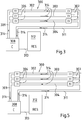
- Nachfolgend wird die Erfindung anhand einer Ausführungsform unter Bezugnahme auf die begleitenden Figuren exemplarisch näher erläutert. Alle Figuren sind rein schematisch und nicht maßstäblich. Es zeigen:
- Fig. 1
- eine schematische Darstellung eines supraleitfähigen Kabels;
- Fig.2
- eine schematische Darstellung des Aufbaus des supraleitfähigen Kabels aus
Figur 1 ; - Fig.3
- ein Kabelsystem aus drei supraleitfähigen Kabeln im Normalbetrieb;
- Fig. 4
- das Kabelsystem aus
Figur 3 in größerer Einzelheit; - Fig. 5
- das Kabelsystem aus
Figur 3 im Abkühlbetrieb; und - Fig. 6
- ein Flussdiagramm des erfindungsgemäßen Verfahrens.
- Gleiche oder ähnliche Elemente sind in den Figuren mit gleichen oder ähnlichen Bezugszeichen versehen.
- In
Figur 1 ist rein schematisch ein supraleitfähiges Kabel 100 dargestellt, das an seinen Enden jeweils einen Endverschluss 101,102 aufweist. Zwischen den Endverschlüssen 101, 102 erstreckt sich ein Kabelkryostat 103, der auch kurz als Kryostat bezeichnet wird. Der Kryostat 103 umschließt mindestens eine supraleitfähige Kabelader. Das supraleitfähige Kabel 100 bestehend aus Kryostat und Kabelader ist inFigur 2 in größerer Einzelheit dargestellt. Die Endverschlüsse 101, 102 ermöglichen den Anschluss Supraleiterkabels an konventionelle Mittelspannungs- oder Hochspannungstechnik und dienen außerdem dazu, den Temperatursprung zwischen dem stickstoffgekühlten supraleitfähigen Kabel und damit in Berührung stehender Komponenten und der Umgebung zu bewältigen. - In einem anderen Ausführungsbeispiel ist anstelle des Endverschlusses 101 und oder des Endverschlusses 102 eine Muffe vorgesehen, die eine Verbindungsstelle zu einem weiteren supraleitfähigen Kabel 100 bildet. Auf diese Weise ist es möglich, das supraleitfähige Kabel 100 zu verlängern.
-
Figur 2 zeigt beispielhaft den Aufbau des supraleitfähigen Kabels 100. Auf einem hohlen Formkörper 200, der einen Hohlraum 201 umschließt, sind supraleitfähige Bänder angeordnet, die eine supraleitfähige Schicht 202 bilden. Die supraleitfähige Schicht 202 ist von einer bandförmigen halbleitenden Leiterglättung 203 umgeben. Auf der Leiterglättung 203 ist ein Dielektrikum 204 angeordnet, dass von einem elektrisch leitenden Schirm 206 umgeben ist, der zum Beispiel aus Kupferdrähten oder Kupferbändern oder ebenfalls aus supraleitfähigen Bändern gebildet ist. Zwischen Dielektrikum 204 und Schirm 206 ist eine weitere halbleitende Schicht (nicht dargestellt) angeordnet. Die halbleitenden Schichten dienen der Glättung des elektrischen Felds im Kabel, indem sie runde Oberflächen schaffen und Kanten eliminieren. - Die genannten Komponenten sind in einem Hohlraum 207 angeordnet, der von einem inneren Kryostatrohr 208 umschlossen ist. Im Betrieb des supraleitfähigen Kabels 100 fließt das zur Kühlung eingesetzte Kühlmittel in dem Hohlraum 207. Die Außenseite des inneren Kryostatrohres 208 ist von einer Superisolation 209 umgeben, die ihrerseits von einem äußeren Kryostatrohr 211 eingeschlossen ist. Der Zwischenraum zwischen dem inneren Kryostatrohr 208 und dem äußeren Kryostatrohr 211 ist evakuiert und bildet eine Vakuumisolation zwischen dem inneren Kryostatrohr 208 und dem äußeren Kryostatrohr 211. Bei manchen Ausführungsbeispielen sind zusätzlich zu der Superisolation 209 Abstandshalter (nicht gezeigt) vorgesehen, die verhindern, dass sich die Kryostatrohre 208, 211 berühren. Die Kryostatrohre 208, 211 sind vorzugsweise aus Edelstahl hergestellt. Mit Vorteil sind die Kryostatrohre 208, quer zu ihrer Längsrichtung oder schraubenlinienförmig gewellt. Zum Schutz vor Beschädigungen und vor anderen Umwelteinflüssen wie Feuchtigkeit oder aggressiven Substanzen ist das äußere Kryostatrohr 211 von einem Mantel umgeben, der beispielsweise aus Polyethylen (PE) oder (PVC) hergestellt ist.
-
Figur 3 zeigt ein supraleitfähiges Kabelsystem 300 mit drei supraleitfähigen Kabeln 302, 303 und 304. Die supraleitfähigen Kabeln 302, 303 und 304 sind beispielsweise so aufgebaut wie das inFigur 2 gezeigte Kabel 100. Jedes der supraleitfähigen Kabel 302, 303, 304 ist an seinem ersten Ende mit einem Endverschluss 306 versehen und an seinem zweiten Ende mit einem Endverschluss 307. Eine Kühlanlage 308 ist über eine Zufuhrleitung 309 für Kühlmittel mit jedem der Endverschlüsse 306 verbunden. Die Endverschlüsse 307 sind über eine Rückleitung 311 für Kühlmittel an die Kühlanlage 308 angeschlossen. Ein Kühlmittelvorratstank 312, der mit Vorteil als Kryotank ausgebildet ist, ist über eine Speiseleitung 313 mit der Kühlanlage 308 verbunden. Die Zufuhrleitung 309, die Rückleitung 311 sowie die Speiseleitung 313 sind vorzugsweise als Kryoleitungen ausgebildet, d.h. als doppelwandige vakuumisolierte Leitungen. - Im Normalbetrieb wird von der Kühlanlage 308 flüssiger Stickstoff über die Zufuhrleitung 309 zu dem Endverschluss 306 gefördert, von wo aus er in die supraleitfähigen Kabel 302-304 eintritt und die Supraleiter kühlt. An den Endverschluss 307 tritt das Kühlmittel wieder aus dem Kryostaten aus und wird über die Rückleitung 311 gesammelt und an die Kühlanlage 308 zurückgeführt. Die Strömungsrichtung des flüssigen Stickstoffs ist in
Figur 3 durch Pfeile 314 angezeigt. Im Betrieb nimmt der als Kühlmittel eingesetzte flüssige Stickstoff Wärme auf, die aus der Umgebung auf das Kabelsystem 300 sowie die damit verbundenen Einrichtungen einstrahlt. Diese Wärme wird von dem Kühlmittel abtransportiert und mittels der Kühlanlage 308 dem Kühlmittel wieder entzogen. Zufuhrleitung 309, supraleitfähige Kabel 302-304, Rückleitung 311 und Kühlanlage 308 bilden einen Kühlkreislauf. Grundsätzlich handelt es sich bei dem Kühlkreislauf um einen geschlossenen Kreislauf. - Nach Betriebsunterbrechungen, zum Beispiel nach einer Reparatur an einem oder mehreren der supraleitfähigen Kabel 302-304, besteht ein Bedarf an zusätzlichem flüssigen Stickstoff, um das betroffene supraleitfähige Kabel bzw. das gesamte Kabelsystem wieder mit flüssigem Stickstoff zu befüllen. Dieser Bedarf an zusätzlichem flüssigem Stickstoff wird aus dem Vorratstank 312 gedeckt und mittels der Speiseleitung 313 der Kühlanlage 308 zugeführt. Verluste an flüssigem Stickstoff, die von kleinen Leckagen in dem Kabelsystem 300 verursacht sind, werden ebenfalls mit flüssigem Stickstoff aus dem Vorratstank 312 wieder ausgeglichen.
-
Figur 4 zeigt die fluidtechnischen Schaltungsmöglichkeiten des Kabelsystems ausFigur 3 in größerer Einzelheit. InFigur 4 sind die Hohlräume 201 und 207, in denen im Betrieb Kühlmittel strömen kann, als getrennte Leitungen gezeigt, die inFigur 4 als Linie dargestellt sind. Insbesondere ist jeder Hohlraum 207 als Außenleiter 401 und jeder innere Hohlraum 201 als Innenleiter 402 dargestellt. In entsprechender Darstellung ist veranschaulicht, dass die Zufuhrleitung 309 ebenfalls aus zwei getrennten Leitungen 403 und 404 aufgebaut ist, die zum Beispiel als Koaxialleitungen in einem gemeinsamen Kryostaten oder als getrennte Leitungen ausgeführt sind. Die Endverschlüsse 306, 307 sind als Wegeventile ausgebildet, die dazu dienen, den Weg des Kühlmittels durch das Kabelsystem, insbesondere durch einzelne Fluid- bzw. Kühlmittelleitungen zu verbinden, zu sperren oder umzulenken, was im Folgenden noch erläutert wird. Die Rückleitung 311 ist als einzelne Rohrleitung ausgebildet, die mittels Absperrungsventilen 406a, 406b von dem Kühlmittelkreislauf abtrennbar ist. - Das insoweit beschriebene Kabelsystem 300 lässt sich durch unterschiedliche fluidtechnische Verschaltungen zahlreiche Betriebsarten des Kabelsystems 300 zu.
- Eine wichtige erste Betriebsart ist der parallele Betrieb des Außen- und Innenleiters 401, 402 in jedem Kabel 302-304, bei dem durch Außen- und Innenleiter 401, 402 das Kühlmittel, insbesondere flüssiger Stickstoff, im Vorlauf strömt. Das Kühlmittel wird durch die Rückleitung 311 zu der Kühlanlage 308 zurückgeführt. Diese Betriebsart weist die größte Kühlleistung auf, sodass das Kabelsystem 300 die tiefste Betriebstemperatur erreicht und infolgedessen die größte Stromtragfähigkeit aufweist. Grundsätzlich gestattet das Kabelsystem 300 auch andere Betriebsarten, die ohne den Einsatz der Rückleitung 311 auskommen. Diese Betriebsarten sind besonders dann vorteilhaft, wenn an der Rückleitung 311 oder einem der supraleitfähigen Kabel 302-304 ein Defekt auftritt.
- Eine zweite Betriebsart wird der Einfachheit halber am Beispiel eines einzigen supraleitfähigen Kabels beschrieben, weil in dieser Betriebsart von einem Kabelsystem mit mehreren supraleitfähigen Kabeln alle Kabel in gleicher Weise betrieben werden. Gemäß dieser zweiten Betriebsart strömt das Kühlmittel in dem Außenleiter 401 im Vorlauf durch das supraleitfähige Kabel und der Innenleiter 402 bildet einen Rücklauf, in welchem das Kühlmittel zurückgeführt wird. Die dafür benötigte Verbindung zwischen dem Außenleiter 401 und dem Innenleiter 402 wird mittels des Endverschlusses 307 und einer Verbindungsleitung 407 hergestellt. In diesem Fall bildet zum Beispiel die Leitung 403 den Vorlauf von der Kühlanlage 308 und die Leitung 404 die Rückleitung zu der Kühlanlage 308.
- Gemäß einer dritten Betriebsart werden in allen Kabeln der Außenleiter 401 unter Innenleiter 402 parallelgeschaltet. Bei dem in
Figur 4 dargestellten konkreten Ausführungsbeispiel bilden beispielsweise die supraleitfähigen Kabel 302 und 303 den Vorlauf, während das Kabel 304 den Rücklauf bildet. Die Kabel 302-304 sind auch mit vertauschten Rollen einsetzbar. Auch in diesem Fall bildet zum Beispiel die Leitung 403 den Vorlauf von der Kühlanlage 308 und die Leitung 404 die Rückleitung zu der Kühlanlage 308. Allgemeiner gesprochen ist es bei der dritten Betriebsart vorgesehen, dass eine Gruppe der supraleitfähigen Kabel des Kabelsystems 300 eine Vorlaufleitung für das Kühlmittel während eine andere Gruppe von supraleitfähigen Kabel eine Rücklaufleitung bildet. - Eine vierte Betriebsart kommt bei einem Kabelsystem zum Einsatz, bei dem die verwendeten supraleitfähigen Kabel nur einen einzigen Kühlkanal aufweisen. Gemäß der vierten Betriebsart wird das Kabelsystem so konfiguriert, dass das Kühlmittel von der Kühlanlage durch zwei Kabel zirkuliert und das dritte Kabel und die Rückleitung aufgewärmt werden können. In einer Variante der vierten Betriebsart zirkuliert der flüssige Stickstoff durch die Rückleitung und eines der Kabel, während die beiden anderen Kabel aufgewärmt werden. Die prinzipielle Funktionsweise unterscheidet sich von der Darstellung in
Figur 4 nur dadurch, dass zum Beispiel die Leitungen 401 in jedem der Kabel 302-304 weglassen sind. - Die beschriebenen vier Betriebsarten sind nur beispielhaft angeführt und aufgrund der Schaltmöglichkeiten der Wegeventile in den Endverschlüssen sind noch andere Betriebsarten für einen Fachmann darstellbar.
- Hierbei ist zu beachten, dass die unterschiedlichen Betriebsarten allein durch geänderte Einstellungen der Wegeventile in den Endverschlüssen 306 bzw. 307 realisiert werden.
- Unabhängig von der gewählten Betriebsart ist es grundsätzlich wünschenswert, das supraleitfähige Kabelsystem langsam abzukühlen, weil besonders in den Endverschlüssen 306,307 Teile aus Kunststoff und faserverstärkten Kunststoff oder Bauteile mit ähnlichen Eigenschaften verbaut sein können, die bei einem sehr schnellen abkühlen Schaden nehmen könnten.
- Das erfindungsgemäße Verfahren zum Abkühlen des Kabelsystems wird nun im Folgenden anhand der ersten Betriebsart mit Bezug auf
Figur 5 beschrieben. - Ausgangspunkt ist ein aufgewärmtes Kabelsystem 300. Die Kühlanlage 308 wird nun so angesteuert, dass flüssiger Stickstoff in die Rückleitung gepumpt wird. Da die Rückleitung auf Umgebungstemperatur ist, verdampft der Stickstoff zumindest in einer Anfangsphase beim Eintritt in die Rückleitung 311. Der dabei entstehende gasförmige Stickstoff strömt durch die Rückleitung durch die Endverschlüsse 307 und kühlt dabei die Endverschlüsse und die supraleitfähigen Kabel 302-304 allmählich ab. Durch den einströmenden flüssigen Stickstoff wird die Rückleitung kontinuierlich immer weiter abgekühlt, sodass der flüssige Stickstoff in der Rückleitung immer weiter in Richtung auf die Endverschlüsse 307 vordringt. Bevor jedoch flüssiger Stickstoff an den Endverschlüssen ankommt, sind die Endverschlüsse 307 und die supraleitfähigen Kabel 302-304 bereits durch das Stickstoffgas auf eine so tiefe Temperatur abgekühlt, sodass es zu keinem Temperaturschock kommt, wenn der flüssige Stickstoff mit den Endverschlüssen 307 in Kontakt kommt. Der Abkühlvorgang kann nun noch eine Weile fortgeführt werden, beispielsweise so lange bis auch an den Endverschlüssen 306 flüssiger Stickstoff ankommt, was beispielsweise mit einem Temperatursensor feststellbar ist oder mittels einer Probenöffnung, aus gegebenenfalls der flüssige Stickstoff ausströmt. Die supraleitfähigen Kabel 302-304 sind dann vollständig mit flüssigem Stickstoff gefüllt. In diesem Moment wird das Wegeventil in der Kühlanlage 308 umgeschaltet und das Kühlmittel strömt in der Richtung durch das Kabelsystem die durch die Pfeile 314 in
Figur 3 gezeigt sind. Die Umschaltung des Wegeventils kann manuell erfolgen. - Das erfindungsgemäße Verfahren zum Abkühlen des Kabelsystems hat den Vorteil, dass kein Verdampfer für flüssigen Stickstoff wie bei herkömmlichen supraleitfähigen Kabelsystemen notwendig ist. Darüber hinaus ermöglichen es die Wegeventile in den Endverschlüssen ein defektes supraleitfähiges Kabel von den anderen supraleitfähigen Kabeln zu isolieren und dieses Kabel aufzuwärmen. Bei dem in
Figur 4 dargestellten Kabelsystem 300 mit drei supraleitfähigen Kabeln ist es beispielsweise möglich, die Kabel 303 und 304 gemäß der zweiten Betriebsart weiter zu betreiben, wenn in dem Kabel 302 ein Defekt auftritt. Das Kabel 302 und die Rückleitung 311 werden in diesem Fall von dem Kühlkreislauf abgetrennt und wärmen sich allmählich auf. Nach einer ausreichenden Wartezeit kann der Defekt repariert werden. Dabei ist es gleichzeitig möglich eine Zirkulation des flüssigen Stickstoffs durch die zwei übrigen Kabel aufrecht zu erhalten, sodass der Betrieb des Kabelsystems auch während der Reparatur fortgesetzt werden kann, wenn auch mit einer geringeren Übertragungskapazität. Nach Abschluss der Reparatur wird das beschriebene Abkühlverfahren wieder angewendet. - In
Figur 6 sind die Wesentlichen Schritte des erfindungsgemäßen Verfahrens, um ein supraleitfähiges Kabelsystem zu kühlen, in einem Flussdiagramm veranschaulicht. In einem ersten Schritt S1 wird das flüssige Kühlmedium, insbesondere flüssiger Stickstoff, in die Rückleitung des Kabelsystems eingeleitet, wo der flüssige Stickstoff unter Wärmeaufnahme verdampft. Das sich so bildende gasförmige Stickstoff breitet sich entlang der Rückleitung in dem Kabelsystem aus. Gemäß einem zweiten Schritt S2 wird der gasförmige Stickstoff durch mindestens ein supraleitfähiges Kabel geleitet. Dabei wird das supraleitfähige Kabel von dem gasförmigen Stickstoff abgekühlt, wobei im Laufe der Zeit die Temperatur immer weiter absinkt. Wenn dabei das supraleitfähige Kabel vollständig mit flüssigem Stickstoff gefüllt ist, wird in einem dritten Schritt S3 die Kühlmittelströmungsrichtung in dem supraleitfähigen Kabelsystem umgekehrt. Das erfindungsgemäße Verfahren hat den Vorteil, dass in dem Kabelsystem keine Verdampfereinrichtung für das Kühlmittel mehr benötigt wird, weil das Kühlmittel während des Abkühlvorganges zunächst in der Rückleitung verdampft, die unempfindlich gegenüber großen Temperaturschwankungen ist. Temperaturempfindliche Bauteile, die beispielsweise in den Endverschlüssen 306,307 angeordnet sind, sind dennoch keinen Temperaturschocks ausgesetzt, weil das Kühlmittel, insbesondere der flüssige Stickstoff, in der Rückleitung verdampft, sodass zunächst nur gasförmiger Stickstoff die Endverschlüsse erreicht. - Auch wenn in der Beschreibung als Kühlmittel stets flüssiger Stickstoff genannt ist so ist die Erfindung nicht auf dieses Kühlmittel beschränkt, sondern auch bei anderen Kühlmitteln einsetzbar.
- Anstelle der Wegeventile können auch Absperrventile eingesetzt werden, die entsprechende Leitungsverbindungen herstellen. Darüber hinaus ist es auch denkbar, dass die Kühlanlage 308 mit einer reversiblen Pumpe ausgestattet ist, um die Strömungsrichtung des Kühlmittels umzukehren.
- In den Ansprüchen schließen die Wörter "aufweisen" und "umfassen" nicht andere Elemente oder Schritte aus und der unbestimmte Artikel "ein" schließt eine Mehrzahl nicht aus.
- Die Tatsache, dass einzelne Funktionen und Elemente in unterschiedlichen abhängigen Ansprüchen aufgeführt sind, bedeutet nicht, dass nicht auch eine Kombination dieser Funktionen und Elemente vorteilhaft verwendet werden könnte.
Bezugszeichenliste 100 supraleitfähiges Kabel 404 Leitung 101,102 Endverschluss 200 hohler Formkörper 406a,406b Absperrventile 201 Hohlraum 202 Supraleitfähige Leiterschicht 203 Schutzhülle 204 Dielektrikum 206 Schirm 207 Hohlraum 208 Inneres Kryostatrohr 209 Superisolation 211 Äußeres Kryostatrohr 212 Mantel 300 Kabelsystem 302-304 Kabel 306,307 Endverschluss 308 Kühlanlage 309 Zufuhrleitung 311 Rückleitung 312 Vorratstank 313 Speiseleitung 314 Strömungsrichtung 401 Außenleiter 402 Innenleiter 403 Leitung
Claims (8)
- Verfahren, um ein supraleitfähiges Kabelsystem (300) mit wenigstens einem supraleitfähigen Kabel (302-304) auf eine Betriebstemperatur unterhalb der Sprungtemperatur zu kühlen, wobei das supraleitfähige Kabel (302-304) innerhalb eines Kryostaten (208; 211) angeordnet ist, der ein thermisch isoliertes Rohr (208) aufweist, welches das supraleitfähige Kabel (302-304) und einen Hohlraum (207) umschließt, wobei das supraleitfähige Kabel mit einem durch den Kryostaten (208; 211) strömenden Kühlmittel, das von einer Kühlanlage (308) abgegeben wird, auf eine Temperatur unterhalb der Sprungtemperatur des supraleitfähigen Kabels kühlbar ist, wobei das Kühlmittel durch eine Rückleitung (311) zu der Kühlanlage zurückströmt, und wobei das Verfahren in einer Normalbetriebsart und einer Abkühlbetriebsart betreibbar ist, dadurch gekennzeichnet, dass die Abkühlbetriebsart folgende Schritte umfasst- Einleiten (S1) von flüssigem Kühlmedium in die Rückleitung (311) des Kabelsystems (300), wobei das Kühlmittel in einer Anfangsphase verdampft;- Durchleiten (S2) des Kühlmittels durch das mindestens eine supraleitfähige Kabel (302-304) in einer ersten Richtung, die das Kühlmittel zu der Kühlanlage (311) zurückführt; und- Umkehren der Kühlmittelströmungsrichtung, wenn das supraleitfähige Kabel auf eine vorgegebene Temperatur abgekühlt ist.
- Verfahren nach Anspruch 1, dadurch gekennzeichnet, dass das Umkehren der Kühlmittelströmungsrichtung dann erfolgt, wenn das Kabel vollständig mit flüssigem Stickstoff gefüllt ist.
- Supraleitfähiges Kabelsystem (300) mit mehreren supraleitfähigen Kabeln (302-304), die jeweils innerhalb eines Kryostaten (208; 211) angeordnet sind, der ein thermisch isoliertes Rohr (208) aufweist, welches das supraleitfähige Kabel und einen Hohlraum (207) umschließt, mit einer Kühlanlage (308), die ein Kühlmittel abgibt, welches durch die Kryostaten (208; 211) der supraleitfähigen Kabel (302-304) strömt und die supraleitfähigen Kabel auf eine Temperatur unterhalb der Sprungtemperatur kühlt, mit einer Rückleitung (311), die das Kühlmittel, welches durch das supraleitfähige Kabel hindurchgeströmt ist, zu der Kühlanlage (308) zurückführt, dadurch gekennzeichnet, dass jedes supraleitfähige Kabel an jedem seiner Enden einen Endverschluss (306, 307) aufweist, der ein Ventil umfasst, um Strömungswege in dem supraleitfähigen Kabelsystem freizugeben, zu sperren und/oder umzulenken.
- Kabelsystem nach Anspruch 3, dadurch gekennzeichnet, dass das Ventil als Wegeventil ausgebildet ist.
- Kabelsystem nach Anspruch 3, dadurch gekennzeichnet, dass die Kühlanlage (308) dazu eingerichtet ist, ein Strömen des Kühlmittels in zwei entgegengesetzte Richtungen zu bewirken.
- Kabelsystem nach Anspruch 3, dadurch gekennzeichnet, dass an den Endverschlüssen (306, 307) Sensoren angeordnet sind, welche die Temperatur des Kühlmittels erfassen.
- Kabelsystem nach Anspruch 6, dadurch gekennzeichnet, dass die Kühlanlage (308) eine Steuereinrichtung aufweist, welche die Sensorsignale empfängt und die Strömungsrichtung des Kühlmittels entsprechend steuert.
- Kabelsystem nach Anspruch 3, dadurch gekennzeichnet, dass die Rückleitung (311) mittels Absperrventilen (406a, 406b) von einem Kühlmittelkreislauf isolierbar ist.
Priority Applications (2)
| Application Number | Priority Date | Filing Date | Title |
|---|---|---|---|
| DK17306827.1T DK3503329T3 (da) | 2017-12-19 | 2017-12-19 | Fremgangsmåde til køling af et superledende kabelsystem |
| EP17306827.1A EP3503329B1 (de) | 2017-12-19 | 2017-12-19 | Verfahren zum kühlen eines supraleitfähigen kabelsystems |
Applications Claiming Priority (1)
| Application Number | Priority Date | Filing Date | Title |
|---|---|---|---|
| EP17306827.1A EP3503329B1 (de) | 2017-12-19 | 2017-12-19 | Verfahren zum kühlen eines supraleitfähigen kabelsystems |
Publications (2)
| Publication Number | Publication Date |
|---|---|
| EP3503329A1 true EP3503329A1 (de) | 2019-06-26 |
| EP3503329B1 EP3503329B1 (de) | 2020-08-05 |
Family
ID=60954824
Family Applications (1)
| Application Number | Title | Priority Date | Filing Date |
|---|---|---|---|
| EP17306827.1A Active EP3503329B1 (de) | 2017-12-19 | 2017-12-19 | Verfahren zum kühlen eines supraleitfähigen kabelsystems |
Country Status (2)
| Country | Link |
|---|---|
| EP (1) | EP3503329B1 (de) |
| DK (1) | DK3503329T3 (de) |
Citations (6)
| Publication number | Priority date | Publication date | Assignee | Title |
|---|---|---|---|---|
| JPH03263710A (ja) * | 1990-03-13 | 1991-11-25 | Kandenko Co Ltd | 超電導電路 |
| EP1667172A1 (de) * | 2003-09-19 | 2006-06-07 | Sumitomo Electric Industries, Ltd. | Supraleitfähiges kabelbetriebsverfahren und supraleitfähiges kabelsystem |
| JP3818328B2 (ja) * | 1996-10-02 | 2006-09-06 | 住友電気工業株式会社 | 極低温ケーブルの冷却装置および冷却方法 |
| EP2418747A1 (de) * | 2010-08-13 | 2012-02-15 | Nexans | Anordnung zum elektrisch leitenden Verbinden von zwei elektrischen Einheiten |
| WO2014026873A2 (de) * | 2012-08-16 | 2014-02-20 | Messer Group Gmbh | Verfahren und vorrichtung zum kühlen von objekten |
| EP2770514A1 (de) | 2013-02-20 | 2014-08-27 | Nexans | Verfahren zum Kühlen eines supraleitfähigen Kabels |
-
2017
- 2017-12-19 EP EP17306827.1A patent/EP3503329B1/de active Active
- 2017-12-19 DK DK17306827.1T patent/DK3503329T3/da active
Patent Citations (6)
| Publication number | Priority date | Publication date | Assignee | Title |
|---|---|---|---|---|
| JPH03263710A (ja) * | 1990-03-13 | 1991-11-25 | Kandenko Co Ltd | 超電導電路 |
| JP3818328B2 (ja) * | 1996-10-02 | 2006-09-06 | 住友電気工業株式会社 | 極低温ケーブルの冷却装置および冷却方法 |
| EP1667172A1 (de) * | 2003-09-19 | 2006-06-07 | Sumitomo Electric Industries, Ltd. | Supraleitfähiges kabelbetriebsverfahren und supraleitfähiges kabelsystem |
| EP2418747A1 (de) * | 2010-08-13 | 2012-02-15 | Nexans | Anordnung zum elektrisch leitenden Verbinden von zwei elektrischen Einheiten |
| WO2014026873A2 (de) * | 2012-08-16 | 2014-02-20 | Messer Group Gmbh | Verfahren und vorrichtung zum kühlen von objekten |
| EP2770514A1 (de) | 2013-02-20 | 2014-08-27 | Nexans | Verfahren zum Kühlen eines supraleitfähigen Kabels |
Also Published As
| Publication number | Publication date |
|---|---|
| DK3503329T3 (da) | 2020-10-26 |
| EP3503329B1 (de) | 2020-08-05 |
Similar Documents
| Publication | Publication Date | Title |
|---|---|---|
| EP2698794B1 (de) | Anordnung mit mindestens einem supraleitfähigen Kabel | |
| EP3281211B1 (de) | Vorrichtung zur gleichstromübertragung | |
| EP2608223B1 (de) | Verfahren zum Kühlen einer Anlage für supraleitfähige Kabel | |
| EP2685469B1 (de) | Anordnung mit mindestens einem supraleitfähigen Kabel | |
| EP2228806B1 (de) | Anordnung zur Strombegrenzung | |
| EP2202762B1 (de) | Anordnung mit einem supraleitfähigen Kabel | |
| EP2418747B1 (de) | Anordnung zum elektrisch leitenden Verbinden von zwei elektrischen Einheiten | |
| EP2328156B1 (de) | Verfahren zum Betrieb einer Anordnung mit mindestens einem supraleitfähigen Kabel | |
| EP2383854A1 (de) | Anordnung mit einem supraleitfähigen Kabel | |
| DE1903643A1 (de) | Verfahren zum Kuehlen eines Verbrauchers,der aus einem teilweise stabilisierten Supraleitungsmagneten besteht | |
| DE102014224363A1 (de) | Vorrichtung der Supraleitungstechnik mitSpuleneinrichtungen und Kühlvorrichtung sowie damitausgestattetes Fahrzeug | |
| EP2426676A1 (de) | Anordnung mit mindestens einem supraleitfähigen Kabel | |
| WO2007107240A1 (de) | Kryostat mit einem magnetspulensystem, das eine lts- und eine gekapselte hts-sektion umfasst | |
| EP2770514B1 (de) | Verfahren zum Kühlen eines supraleitfähigen Kabels | |
| EP2234122B1 (de) | Supraleitfähiges elektrisches Kabel | |
| EP3749903B1 (de) | Verfahren und vorrichtung zum kühlen eines supraleitenden stromträgers | |
| EP0082409B1 (de) | Thermisches Verfahren zum schnellen Überführen einer supraleitenden Wicklung vom supraleitenden in den normalleitenden Zustand und Vorrichtung zur Durchführung des Verfahrens | |
| DE202019003381U1 (de) | Muffe für ein supraleitfähiges Kabel und supraleitfähiges Kabel mit Anschluss für eine Zwischenkühlung | |
| DE102012016292A1 (de) | Verfahren und Vorrichtung zum Kühlen von Objekten | |
| DE8804371U1 (de) | Supraleitendes Kabel mit oxidkeramischem Hochtemperatursupraleiter-Material | |
| EP1865516B1 (de) | System mit einem supraleitfähigen Kabel | |
| DE102004057204B4 (de) | Supraleitungseinrichtung mit Kryosystem und supraleitendem Schalter | |
| EP3503329B1 (de) | Verfahren zum kühlen eines supraleitfähigen kabelsystems | |
| DE102004031908B3 (de) | Strombegrenzungseinrichtung mit supraleitendem Schaltelement | |
| EP3525306B1 (de) | Supraleitfähiges kabelsystem mit überdruckschutz |
Legal Events
| Date | Code | Title | Description |
|---|---|---|---|
| PUAI | Public reference made under article 153(3) epc to a published international application that has entered the european phase |
Free format text: ORIGINAL CODE: 0009012 |
|
| STAA | Information on the status of an ep patent application or granted ep patent |
Free format text: STATUS: THE APPLICATION HAS BEEN PUBLISHED |
|
| AK | Designated contracting states |
Kind code of ref document: A1 Designated state(s): AL AT BE BG CH CY CZ DE DK EE ES FI FR GB GR HR HU IE IS IT LI LT LU LV MC MK MT NL NO PL PT RO RS SE SI SK SM TR |
|
| AX | Request for extension of the european patent |
Extension state: BA ME |
|
| STAA | Information on the status of an ep patent application or granted ep patent |
Free format text: STATUS: REQUEST FOR EXAMINATION WAS MADE |
|
| 17P | Request for examination filed |
Effective date: 20200102 |
|
| RBV | Designated contracting states (corrected) |
Designated state(s): AL AT BE BG CH CY CZ DE DK EE ES FI FR GB GR HR HU IE IS IT LI LT LU LV MC MK MT NL NO PL PT RO RS SE SI SK SM TR |
|
| GRAP | Despatch of communication of intention to grant a patent |
Free format text: ORIGINAL CODE: EPIDOSNIGR1 |
|
| STAA | Information on the status of an ep patent application or granted ep patent |
Free format text: STATUS: GRANT OF PATENT IS INTENDED |
|
| RIC1 | Information provided on ipc code assigned before grant |
Ipc: H01B 12/16 20060101ALN20200204BHEP Ipc: H02G 15/34 20060101AFI20200204BHEP |
|
| RIC1 | Information provided on ipc code assigned before grant |
Ipc: H02G 15/34 20060101AFI20200210BHEP Ipc: H01B 12/16 20060101ALN20200210BHEP |
|
| INTG | Intention to grant announced |
Effective date: 20200224 |
|
| GRAS | Grant fee paid |
Free format text: ORIGINAL CODE: EPIDOSNIGR3 |
|
| GRAA | (expected) grant |
Free format text: ORIGINAL CODE: 0009210 |
|
| STAA | Information on the status of an ep patent application or granted ep patent |
Free format text: STATUS: THE PATENT HAS BEEN GRANTED |
|
| AK | Designated contracting states |
Kind code of ref document: B1 Designated state(s): AL AT BE BG CH CY CZ DE DK EE ES FI FR GB GR HR HU IE IS IT LI LT LU LV MC MK MT NL NO PL PT RO RS SE SI SK SM TR |
|
| REG | Reference to a national code |
Ref country code: GB Ref legal event code: FG4D Free format text: NOT ENGLISH |
|
| REG | Reference to a national code |
Ref country code: CH Ref legal event code: EP |
|
| REG | Reference to a national code |
Ref country code: AT Ref legal event code: REF Ref document number: 1300065 Country of ref document: AT Kind code of ref document: T Effective date: 20200815 |
|
| REG | Reference to a national code |
Ref country code: DE Ref legal event code: R096 Ref document number: 502017006548 Country of ref document: DE |
|
| REG | Reference to a national code |
Ref country code: IE Ref legal event code: FG4D Free format text: LANGUAGE OF EP DOCUMENT: GERMAN |
|
| REG | Reference to a national code |
Ref country code: DK Ref legal event code: T3 Effective date: 20201023 |
|
| REG | Reference to a national code |
Ref country code: LT Ref legal event code: MG4D |
|
| REG | Reference to a national code |
Ref country code: NL Ref legal event code: MP Effective date: 20200805 |
|
| PG25 | Lapsed in a contracting state [announced via postgrant information from national office to epo] |
Ref country code: BG Free format text: LAPSE BECAUSE OF FAILURE TO SUBMIT A TRANSLATION OF THE DESCRIPTION OR TO PAY THE FEE WITHIN THE PRESCRIBED TIME-LIMIT Effective date: 20201105 Ref country code: SE Free format text: LAPSE BECAUSE OF FAILURE TO SUBMIT A TRANSLATION OF THE DESCRIPTION OR TO PAY THE FEE WITHIN THE PRESCRIBED TIME-LIMIT Effective date: 20200805 Ref country code: GR Free format text: LAPSE BECAUSE OF FAILURE TO SUBMIT A TRANSLATION OF THE DESCRIPTION OR TO PAY THE FEE WITHIN THE PRESCRIBED TIME-LIMIT Effective date: 20201106 Ref country code: NO Free format text: LAPSE BECAUSE OF FAILURE TO SUBMIT A TRANSLATION OF THE DESCRIPTION OR TO PAY THE FEE WITHIN THE PRESCRIBED TIME-LIMIT Effective date: 20201105 Ref country code: ES Free format text: LAPSE BECAUSE OF FAILURE TO SUBMIT A TRANSLATION OF THE DESCRIPTION OR TO PAY THE FEE WITHIN THE PRESCRIBED TIME-LIMIT Effective date: 20200805 Ref country code: HR Free format text: LAPSE BECAUSE OF FAILURE TO SUBMIT A TRANSLATION OF THE DESCRIPTION OR TO PAY THE FEE WITHIN THE PRESCRIBED TIME-LIMIT Effective date: 20200805 Ref country code: PT Free format text: LAPSE BECAUSE OF FAILURE TO SUBMIT A TRANSLATION OF THE DESCRIPTION OR TO PAY THE FEE WITHIN THE PRESCRIBED TIME-LIMIT Effective date: 20201207 Ref country code: LT Free format text: LAPSE BECAUSE OF FAILURE TO SUBMIT A TRANSLATION OF THE DESCRIPTION OR TO PAY THE FEE WITHIN THE PRESCRIBED TIME-LIMIT Effective date: 20200805 Ref country code: FI Free format text: LAPSE BECAUSE OF FAILURE TO SUBMIT A TRANSLATION OF THE DESCRIPTION OR TO PAY THE FEE WITHIN THE PRESCRIBED TIME-LIMIT Effective date: 20200805 |
|
| PG25 | Lapsed in a contracting state [announced via postgrant information from national office to epo] |
Ref country code: IS Free format text: LAPSE BECAUSE OF FAILURE TO SUBMIT A TRANSLATION OF THE DESCRIPTION OR TO PAY THE FEE WITHIN THE PRESCRIBED TIME-LIMIT Effective date: 20201205 Ref country code: LV Free format text: LAPSE BECAUSE OF FAILURE TO SUBMIT A TRANSLATION OF THE DESCRIPTION OR TO PAY THE FEE WITHIN THE PRESCRIBED TIME-LIMIT Effective date: 20200805 Ref country code: NL Free format text: LAPSE BECAUSE OF FAILURE TO SUBMIT A TRANSLATION OF THE DESCRIPTION OR TO PAY THE FEE WITHIN THE PRESCRIBED TIME-LIMIT Effective date: 20200805 Ref country code: RS Free format text: LAPSE BECAUSE OF FAILURE TO SUBMIT A TRANSLATION OF THE DESCRIPTION OR TO PAY THE FEE WITHIN THE PRESCRIBED TIME-LIMIT Effective date: 20200805 Ref country code: PL Free format text: LAPSE BECAUSE OF FAILURE TO SUBMIT A TRANSLATION OF THE DESCRIPTION OR TO PAY THE FEE WITHIN THE PRESCRIBED TIME-LIMIT Effective date: 20200805 |
|
| PG25 | Lapsed in a contracting state [announced via postgrant information from national office to epo] |
Ref country code: SM Free format text: LAPSE BECAUSE OF FAILURE TO SUBMIT A TRANSLATION OF THE DESCRIPTION OR TO PAY THE FEE WITHIN THE PRESCRIBED TIME-LIMIT Effective date: 20200805 Ref country code: EE Free format text: LAPSE BECAUSE OF FAILURE TO SUBMIT A TRANSLATION OF THE DESCRIPTION OR TO PAY THE FEE WITHIN THE PRESCRIBED TIME-LIMIT Effective date: 20200805 Ref country code: CZ Free format text: LAPSE BECAUSE OF FAILURE TO SUBMIT A TRANSLATION OF THE DESCRIPTION OR TO PAY THE FEE WITHIN THE PRESCRIBED TIME-LIMIT Effective date: 20200805 Ref country code: RO Free format text: LAPSE BECAUSE OF FAILURE TO SUBMIT A TRANSLATION OF THE DESCRIPTION OR TO PAY THE FEE WITHIN THE PRESCRIBED TIME-LIMIT Effective date: 20200805 |
|
| REG | Reference to a national code |
Ref country code: DE Ref legal event code: R097 Ref document number: 502017006548 Country of ref document: DE |
|
| PG25 | Lapsed in a contracting state [announced via postgrant information from national office to epo] |
Ref country code: AL Free format text: LAPSE BECAUSE OF FAILURE TO SUBMIT A TRANSLATION OF THE DESCRIPTION OR TO PAY THE FEE WITHIN THE PRESCRIBED TIME-LIMIT Effective date: 20200805 |
|
| PLBE | No opposition filed within time limit |
Free format text: ORIGINAL CODE: 0009261 |
|
| STAA | Information on the status of an ep patent application or granted ep patent |
Free format text: STATUS: NO OPPOSITION FILED WITHIN TIME LIMIT |
|
| PG25 | Lapsed in a contracting state [announced via postgrant information from national office to epo] |
Ref country code: SK Free format text: LAPSE BECAUSE OF FAILURE TO SUBMIT A TRANSLATION OF THE DESCRIPTION OR TO PAY THE FEE WITHIN THE PRESCRIBED TIME-LIMIT Effective date: 20200805 |
|
| 26N | No opposition filed |
Effective date: 20210507 |
|
| PG25 | Lapsed in a contracting state [announced via postgrant information from national office to epo] |
Ref country code: IT Free format text: LAPSE BECAUSE OF FAILURE TO SUBMIT A TRANSLATION OF THE DESCRIPTION OR TO PAY THE FEE WITHIN THE PRESCRIBED TIME-LIMIT Effective date: 20200805 |
|
| REG | Reference to a national code |
Ref country code: CH Ref legal event code: PL |
|
| PG25 | Lapsed in a contracting state [announced via postgrant information from national office to epo] |
Ref country code: MC Free format text: LAPSE BECAUSE OF FAILURE TO SUBMIT A TRANSLATION OF THE DESCRIPTION OR TO PAY THE FEE WITHIN THE PRESCRIBED TIME-LIMIT Effective date: 20200805 Ref country code: SI Free format text: LAPSE BECAUSE OF FAILURE TO SUBMIT A TRANSLATION OF THE DESCRIPTION OR TO PAY THE FEE WITHIN THE PRESCRIBED TIME-LIMIT Effective date: 20200805 |
|
| REG | Reference to a national code |
Ref country code: BE Ref legal event code: MM Effective date: 20201231 |
|
| PG25 | Lapsed in a contracting state [announced via postgrant information from national office to epo] |
Ref country code: IE Free format text: LAPSE BECAUSE OF NON-PAYMENT OF DUE FEES Effective date: 20201219 Ref country code: LU Free format text: LAPSE BECAUSE OF NON-PAYMENT OF DUE FEES Effective date: 20201219 |
|
| PG25 | Lapsed in a contracting state [announced via postgrant information from national office to epo] |
Ref country code: CH Free format text: LAPSE BECAUSE OF NON-PAYMENT OF DUE FEES Effective date: 20201231 Ref country code: LI Free format text: LAPSE BECAUSE OF NON-PAYMENT OF DUE FEES Effective date: 20201231 |
|
| PG25 | Lapsed in a contracting state [announced via postgrant information from national office to epo] |
Ref country code: TR Free format text: LAPSE BECAUSE OF FAILURE TO SUBMIT A TRANSLATION OF THE DESCRIPTION OR TO PAY THE FEE WITHIN THE PRESCRIBED TIME-LIMIT Effective date: 20200805 Ref country code: MT Free format text: LAPSE BECAUSE OF FAILURE TO SUBMIT A TRANSLATION OF THE DESCRIPTION OR TO PAY THE FEE WITHIN THE PRESCRIBED TIME-LIMIT Effective date: 20200805 Ref country code: CY Free format text: LAPSE BECAUSE OF FAILURE TO SUBMIT A TRANSLATION OF THE DESCRIPTION OR TO PAY THE FEE WITHIN THE PRESCRIBED TIME-LIMIT Effective date: 20200805 |
|
| PG25 | Lapsed in a contracting state [announced via postgrant information from national office to epo] |
Ref country code: MK Free format text: LAPSE BECAUSE OF FAILURE TO SUBMIT A TRANSLATION OF THE DESCRIPTION OR TO PAY THE FEE WITHIN THE PRESCRIBED TIME-LIMIT Effective date: 20200805 |
|
| PG25 | Lapsed in a contracting state [announced via postgrant information from national office to epo] |
Ref country code: BE Free format text: LAPSE BECAUSE OF NON-PAYMENT OF DUE FEES Effective date: 20201231 |
|
| GBPC | Gb: european patent ceased through non-payment of renewal fee |
Effective date: 20211219 |
|
| PG25 | Lapsed in a contracting state [announced via postgrant information from national office to epo] |
Ref country code: GB Free format text: LAPSE BECAUSE OF NON-PAYMENT OF DUE FEES Effective date: 20211219 |
|
| REG | Reference to a national code |
Ref country code: AT Ref legal event code: MM01 Ref document number: 1300065 Country of ref document: AT Kind code of ref document: T Effective date: 20221219 |
|
| PG25 | Lapsed in a contracting state [announced via postgrant information from national office to epo] |
Ref country code: AT Free format text: LAPSE BECAUSE OF NON-PAYMENT OF DUE FEES Effective date: 20221219 |
|
| PG25 | Lapsed in a contracting state [announced via postgrant information from national office to epo] |
Ref country code: AT Free format text: LAPSE BECAUSE OF NON-PAYMENT OF DUE FEES Effective date: 20221219 |
|
| PGFP | Annual fee paid to national office [announced via postgrant information from national office to epo] |
Ref country code: DE Payment date: 20251211 Year of fee payment: 9 |
|
| PGFP | Annual fee paid to national office [announced via postgrant information from national office to epo] |
Ref country code: DK Payment date: 20251224 Year of fee payment: 9 |
|
| PGFP | Annual fee paid to national office [announced via postgrant information from national office to epo] |
Ref country code: FR Payment date: 20251229 Year of fee payment: 9 |
|
| PGFP | Annual fee paid to national office [announced via postgrant information from national office to epo] |
Ref country code: AT Payment date: 20260410 Year of fee payment: 5 |