EP3503251A1 - Method for producing fuel cell separator, and separator material - Google Patents
Method for producing fuel cell separator, and separator material Download PDFInfo
- Publication number
- EP3503251A1 EP3503251A1 EP18211249.0A EP18211249A EP3503251A1 EP 3503251 A1 EP3503251 A1 EP 3503251A1 EP 18211249 A EP18211249 A EP 18211249A EP 3503251 A1 EP3503251 A1 EP 3503251A1
- Authority
- EP
- European Patent Office
- Prior art keywords
- layer
- resin
- carbon
- separator
- fuel cell
- Prior art date
- Legal status (The legal status is an assumption and is not a legal conclusion. Google has not performed a legal analysis and makes no representation as to the accuracy of the status listed.)
- Withdrawn
Links
- 239000000446 fuel Substances 0.000 title claims abstract description 52
- 239000000463 material Substances 0.000 title claims abstract description 50
- 238000004519 manufacturing process Methods 0.000 title claims abstract description 21
- 229920005989 resin Polymers 0.000 claims abstract description 155
- 239000011347 resin Substances 0.000 claims abstract description 155
- OKTJSMMVPCPJKN-UHFFFAOYSA-N Carbon Chemical compound [C] OKTJSMMVPCPJKN-UHFFFAOYSA-N 0.000 claims abstract description 120
- 229910052799 carbon Inorganic materials 0.000 claims abstract description 120
- 239000000758 substrate Substances 0.000 claims abstract description 76
- RTAQQCXQSZGOHL-UHFFFAOYSA-N Titanium Chemical compound [Ti] RTAQQCXQSZGOHL-UHFFFAOYSA-N 0.000 claims abstract description 65
- 239000010936 titanium Substances 0.000 claims abstract description 57
- 229910052719 titanium Inorganic materials 0.000 claims abstract description 57
- 239000007789 gas Substances 0.000 claims abstract description 41
- 229910052751 metal Inorganic materials 0.000 claims abstract description 30
- 239000002184 metal Substances 0.000 claims abstract description 30
- 238000000034 method Methods 0.000 claims abstract description 11
- 239000007800 oxidant agent Substances 0.000 claims abstract description 10
- 230000001590 oxidative effect Effects 0.000 claims abstract description 10
- 239000002737 fuel gas Substances 0.000 claims abstract description 9
- 239000006229 carbon black Substances 0.000 claims description 77
- 239000002245 particle Substances 0.000 claims description 46
- 239000000725 suspension Substances 0.000 claims description 31
- 239000000203 mixture Substances 0.000 claims description 27
- 229920000178 Acrylic resin Polymers 0.000 claims description 22
- 239000004925 Acrylic resin Substances 0.000 claims description 22
- 239000002270 dispersing agent Substances 0.000 claims description 19
- 229920005992 thermoplastic resin Polymers 0.000 claims description 17
- 235000014113 dietary fatty acids Nutrition 0.000 claims description 15
- 239000000194 fatty acid Substances 0.000 claims description 15
- 229930195729 fatty acid Natural products 0.000 claims description 15
- 150000004665 fatty acids Chemical class 0.000 claims description 14
- 238000010438 heat treatment Methods 0.000 claims description 14
- 239000007788 liquid Substances 0.000 claims description 13
- GWEVSGVZZGPLCZ-UHFFFAOYSA-N Titan oxide Chemical compound O=[Ti]=O GWEVSGVZZGPLCZ-UHFFFAOYSA-N 0.000 claims description 11
- 239000000314 lubricant Substances 0.000 claims description 11
- OGIDPMRJRNCKJF-UHFFFAOYSA-N titanium oxide Inorganic materials [Ti]=O OGIDPMRJRNCKJF-UHFFFAOYSA-N 0.000 claims description 11
- 229910001069 Ti alloy Inorganic materials 0.000 claims description 8
- 238000001035 drying Methods 0.000 claims description 2
- 125000005313 fatty acid group Chemical group 0.000 claims 1
- 239000010410 layer Substances 0.000 description 234
- 239000012528 membrane Substances 0.000 description 12
- 238000009792 diffusion process Methods 0.000 description 11
- 239000002609 medium Substances 0.000 description 10
- 239000002904 solvent Substances 0.000 description 10
- 125000000391 vinyl group Chemical group [H]C([*])=C([H])[H] 0.000 description 9
- 229920002554 vinyl polymer Polymers 0.000 description 9
- 238000003754 machining Methods 0.000 description 6
- -1 polyethylene Polymers 0.000 description 6
- QVGXLLKOCUKJST-UHFFFAOYSA-N atomic oxygen Chemical compound [O] QVGXLLKOCUKJST-UHFFFAOYSA-N 0.000 description 5
- 239000001301 oxygen Substances 0.000 description 5
- 229910052760 oxygen Inorganic materials 0.000 description 5
- 238000003825 pressing Methods 0.000 description 5
- 230000007547 defect Effects 0.000 description 4
- 239000003792 electrolyte Substances 0.000 description 4
- NIXOWILDQLNWCW-UHFFFAOYSA-M Acrylate Chemical compound [O-]C(=O)C=C NIXOWILDQLNWCW-UHFFFAOYSA-M 0.000 description 3
- LFQSCWFLJHTTHZ-UHFFFAOYSA-N Ethanol Chemical compound CCO LFQSCWFLJHTTHZ-UHFFFAOYSA-N 0.000 description 3
- 239000011248 coating agent Substances 0.000 description 3
- 238000000576 coating method Methods 0.000 description 3
- 239000005518 polymer electrolyte Substances 0.000 description 3
- 238000010248 power generation Methods 0.000 description 3
- 239000007787 solid Substances 0.000 description 3
- 239000010935 stainless steel Substances 0.000 description 3
- 229910001220 stainless steel Inorganic materials 0.000 description 3
- XLYOFNOQVPJJNP-UHFFFAOYSA-N water Substances O XLYOFNOQVPJJNP-UHFFFAOYSA-N 0.000 description 3
- CURLTUGMZLYLDI-UHFFFAOYSA-N Carbon dioxide Chemical compound O=C=O CURLTUGMZLYLDI-UHFFFAOYSA-N 0.000 description 2
- MYMOFIZGZYHOMD-UHFFFAOYSA-N Dioxygen Chemical compound O=O MYMOFIZGZYHOMD-UHFFFAOYSA-N 0.000 description 2
- VZCYOOQTPOCHFL-OWOJBTEDSA-N Fumaric acid Chemical compound OC(=O)\C=C\C(O)=O VZCYOOQTPOCHFL-OWOJBTEDSA-N 0.000 description 2
- UFHFLCQGNIYNRP-UHFFFAOYSA-N Hydrogen Chemical compound [H][H] UFHFLCQGNIYNRP-UHFFFAOYSA-N 0.000 description 2
- CDBYLPFSWZWCQE-UHFFFAOYSA-L Sodium Carbonate Chemical compound [Na+].[Na+].[O-]C([O-])=O CDBYLPFSWZWCQE-UHFFFAOYSA-L 0.000 description 2
- PPBRXRYQALVLMV-UHFFFAOYSA-N Styrene Chemical compound C=CC1=CC=CC=C1 PPBRXRYQALVLMV-UHFFFAOYSA-N 0.000 description 2
- 239000012670 alkaline solution Substances 0.000 description 2
- 229910001882 dioxygen Inorganic materials 0.000 description 2
- UKMSUNONTOPOIO-UHFFFAOYSA-N docosanoic acid Chemical compound CCCCCCCCCCCCCCCCCCCCCC(O)=O UKMSUNONTOPOIO-UHFFFAOYSA-N 0.000 description 2
- POULHZVOKOAJMA-UHFFFAOYSA-N dodecanoic acid Chemical compound CCCCCCCCCCCC(O)=O POULHZVOKOAJMA-UHFFFAOYSA-N 0.000 description 2
- 238000003487 electrochemical reaction Methods 0.000 description 2
- KEMQGTRYUADPNZ-UHFFFAOYSA-N heptadecanoic acid Chemical compound CCCCCCCCCCCCCCCCC(O)=O KEMQGTRYUADPNZ-UHFFFAOYSA-N 0.000 description 2
- IPCSVZSSVZVIGE-UHFFFAOYSA-N hexadecanoic acid Chemical compound CCCCCCCCCCCCCCCC(O)=O IPCSVZSSVZVIGE-UHFFFAOYSA-N 0.000 description 2
- VKOBVWXKNCXXDE-UHFFFAOYSA-N icosanoic acid Chemical compound CCCCCCCCCCCCCCCCCCCC(O)=O VKOBVWXKNCXXDE-UHFFFAOYSA-N 0.000 description 2
- 239000000178 monomer Substances 0.000 description 2
- BASFCYQUMIYNBI-UHFFFAOYSA-N platinum Chemical compound [Pt] BASFCYQUMIYNBI-UHFFFAOYSA-N 0.000 description 2
- 238000005507 spraying Methods 0.000 description 2
- VZCYOOQTPOCHFL-UHFFFAOYSA-N trans-butenedioic acid Natural products OC(=O)C=CC(O)=O VZCYOOQTPOCHFL-UHFFFAOYSA-N 0.000 description 2
- JAHNSTQSQJOJLO-UHFFFAOYSA-N 2-(3-fluorophenyl)-1h-imidazole Chemical compound FC1=CC=CC(C=2NC=CN=2)=C1 JAHNSTQSQJOJLO-UHFFFAOYSA-N 0.000 description 1
- 235000021357 Behenic acid Nutrition 0.000 description 1
- 239000005639 Lauric acid Substances 0.000 description 1
- 235000021353 Lignoceric acid Nutrition 0.000 description 1
- CQXMAMUUWHYSIY-UHFFFAOYSA-N Lignoceric acid Natural products CCCCCCCCCCCCCCCCCCCCCCCC(=O)OCCC1=CC=C(O)C=C1 CQXMAMUUWHYSIY-UHFFFAOYSA-N 0.000 description 1
- CERQOIWHTDAKMF-UHFFFAOYSA-N Methacrylic acid Chemical compound CC(=C)C(O)=O CERQOIWHTDAKMF-UHFFFAOYSA-N 0.000 description 1
- 238000010629 Molecular evolutionary genetics analysis Methods 0.000 description 1
- 239000004677 Nylon Substances 0.000 description 1
- 235000021314 Palmitic acid Nutrition 0.000 description 1
- 229930182556 Polyacetal Natural products 0.000 description 1
- 239000004698 Polyethylene Substances 0.000 description 1
- 239000004743 Polypropylene Substances 0.000 description 1
- 239000004372 Polyvinyl alcohol Substances 0.000 description 1
- 229920001328 Polyvinylidene chloride Polymers 0.000 description 1
- OFOBLEOULBTSOW-UHFFFAOYSA-N Propanedioic acid Natural products OC(=O)CC(O)=O OFOBLEOULBTSOW-UHFFFAOYSA-N 0.000 description 1
- 235000021355 Stearic acid Nutrition 0.000 description 1
- 229910004349 Ti-Al Inorganic materials 0.000 description 1
- 229910004692 Ti—Al Inorganic materials 0.000 description 1
- 229910010977 Ti—Pd Inorganic materials 0.000 description 1
- DHKHKXVYLBGOIT-UHFFFAOYSA-N acetaldehyde Diethyl Acetal Natural products CCOC(C)OCC DHKHKXVYLBGOIT-UHFFFAOYSA-N 0.000 description 1
- 125000002777 acetyl group Chemical class [H]C([H])([H])C(*)=O 0.000 description 1
- 239000002253 acid Substances 0.000 description 1
- 239000007864 aqueous solution Substances 0.000 description 1
- 229940116226 behenic acid Drugs 0.000 description 1
- 125000004432 carbon atom Chemical group C* 0.000 description 1
- 239000001569 carbon dioxide Substances 0.000 description 1
- 229910002092 carbon dioxide Inorganic materials 0.000 description 1
- 239000003575 carbonaceous material Substances 0.000 description 1
- 150000001735 carboxylic acids Chemical class 0.000 description 1
- 239000003054 catalyst Substances 0.000 description 1
- 238000006243 chemical reaction Methods 0.000 description 1
- 229920006026 co-polymeric resin Polymers 0.000 description 1
- 239000011247 coating layer Substances 0.000 description 1
- 238000001816 cooling Methods 0.000 description 1
- 229920001577 copolymer Polymers 0.000 description 1
- LDHQCZJRKDOVOX-NSCUHMNNSA-N crotonic acid Chemical compound C\C=C\C(O)=O LDHQCZJRKDOVOX-NSCUHMNNSA-N 0.000 description 1
- 238000007607 die coating method Methods 0.000 description 1
- 238000003618 dip coating Methods 0.000 description 1
- 239000002612 dispersion medium Substances 0.000 description 1
- 238000004090 dissolution Methods 0.000 description 1
- 230000000694 effects Effects 0.000 description 1
- FARYTWBWLZAXNK-WAYWQWQTSA-N ethyl (z)-3-(methylamino)but-2-enoate Chemical compound CCOC(=O)\C=C(\C)NC FARYTWBWLZAXNK-WAYWQWQTSA-N 0.000 description 1
- 125000001495 ethyl group Chemical group [H]C([H])([H])C([H])([H])* 0.000 description 1
- 239000004744 fabric Substances 0.000 description 1
- 239000006260 foam Substances 0.000 description 1
- 239000001530 fumaric acid Substances 0.000 description 1
- 238000007756 gravure coating Methods 0.000 description 1
- 229920001519 homopolymer Polymers 0.000 description 1
- 238000007641 inkjet printing Methods 0.000 description 1
- 239000003014 ion exchange membrane Substances 0.000 description 1
- 125000001449 isopropyl group Chemical group [H]C([H])([H])C([H])(*)C([H])([H])[H] 0.000 description 1
- VZCYOOQTPOCHFL-UPHRSURJSA-N maleic acid Chemical compound OC(=O)\C=C/C(O)=O VZCYOOQTPOCHFL-UPHRSURJSA-N 0.000 description 1
- 239000011976 maleic acid Substances 0.000 description 1
- ADFPJHOAARPYLP-UHFFFAOYSA-N methyl 2-methylprop-2-enoate;styrene Chemical compound COC(=O)C(C)=C.C=CC1=CC=CC=C1 ADFPJHOAARPYLP-UHFFFAOYSA-N 0.000 description 1
- 125000002496 methyl group Chemical group [H]C([H])([H])* 0.000 description 1
- LVHBHZANLOWSRM-UHFFFAOYSA-N methylenebutanedioic acid Natural products OC(=O)CC(=C)C(O)=O LVHBHZANLOWSRM-UHFFFAOYSA-N 0.000 description 1
- WQEPLUUGTLDZJY-UHFFFAOYSA-N n-Pentadecanoic acid Natural products CCCCCCCCCCCCCCC(O)=O WQEPLUUGTLDZJY-UHFFFAOYSA-N 0.000 description 1
- 229910052758 niobium Inorganic materials 0.000 description 1
- 229920001778 nylon Polymers 0.000 description 1
- QIQXTHQIDYTFRH-UHFFFAOYSA-N octadecanoic acid Chemical compound CCCCCCCCCCCCCCCCCC(O)=O QIQXTHQIDYTFRH-UHFFFAOYSA-N 0.000 description 1
- OQCDKBAXFALNLD-UHFFFAOYSA-N octadecanoic acid Natural products CCCCCCCC(C)CCCCCCCCC(O)=O OQCDKBAXFALNLD-UHFFFAOYSA-N 0.000 description 1
- 239000003960 organic solvent Substances 0.000 description 1
- 238000005268 plasma chemical vapour deposition Methods 0.000 description 1
- 238000001020 plasma etching Methods 0.000 description 1
- 229910052697 platinum Inorganic materials 0.000 description 1
- 229920005668 polycarbonate resin Polymers 0.000 description 1
- 239000004431 polycarbonate resin Substances 0.000 description 1
- 229920001225 polyester resin Polymers 0.000 description 1
- 239000004645 polyester resin Substances 0.000 description 1
- 229920000573 polyethylene Polymers 0.000 description 1
- 239000002861 polymer material Substances 0.000 description 1
- 229920005672 polyolefin resin Polymers 0.000 description 1
- 229920006324 polyoxymethylene Polymers 0.000 description 1
- 229920001155 polypropylene Polymers 0.000 description 1
- 229920002689 polyvinyl acetate Polymers 0.000 description 1
- 239000011118 polyvinyl acetate Substances 0.000 description 1
- 229920002451 polyvinyl alcohol Polymers 0.000 description 1
- 229920000915 polyvinyl chloride Polymers 0.000 description 1
- 239000004800 polyvinyl chloride Substances 0.000 description 1
- 239000005033 polyvinylidene chloride Substances 0.000 description 1
- 239000003507 refrigerant Substances 0.000 description 1
- 229910000029 sodium carbonate Inorganic materials 0.000 description 1
- 239000000243 solution Substances 0.000 description 1
- 238000004528 spin coating Methods 0.000 description 1
- 239000008117 stearic acid Substances 0.000 description 1
- 125000005472 straight-chain saturated fatty acid group Chemical group 0.000 description 1
- 229910052715 tantalum Inorganic materials 0.000 description 1
- LDHQCZJRKDOVOX-UHFFFAOYSA-N trans-crotonic acid Natural products CC=CC(O)=O LDHQCZJRKDOVOX-UHFFFAOYSA-N 0.000 description 1
- 229910052720 vanadium Inorganic materials 0.000 description 1
Images




Classifications
-
- H—ELECTRICITY
- H01—ELECTRIC ELEMENTS
- H01M—PROCESSES OR MEANS, e.g. BATTERIES, FOR THE DIRECT CONVERSION OF CHEMICAL ENERGY INTO ELECTRICAL ENERGY
- H01M8/00—Fuel cells; Manufacture thereof
- H01M8/02—Details
- H01M8/0202—Collectors; Separators, e.g. bipolar separators; Interconnectors
- H01M8/0204—Non-porous and characterised by the material
- H01M8/0223—Composites
- H01M8/0228—Composites in the form of layered or coated products
-
- H—ELECTRICITY
- H01—ELECTRIC ELEMENTS
- H01M—PROCESSES OR MEANS, e.g. BATTERIES, FOR THE DIRECT CONVERSION OF CHEMICAL ENERGY INTO ELECTRICAL ENERGY
- H01M8/00—Fuel cells; Manufacture thereof
- H01M8/02—Details
- H01M8/0202—Collectors; Separators, e.g. bipolar separators; Interconnectors
-
- C—CHEMISTRY; METALLURGY
- C01—INORGANIC CHEMISTRY
- C01B—NON-METALLIC ELEMENTS; COMPOUNDS THEREOF; METALLOIDS OR COMPOUNDS THEREOF NOT COVERED BY SUBCLASS C01C
- C01B32/00—Carbon; Compounds thereof
- C01B32/15—Nano-sized carbon materials
- C01B32/182—Graphene
-
- C—CHEMISTRY; METALLURGY
- C01—INORGANIC CHEMISTRY
- C01B—NON-METALLIC ELEMENTS; COMPOUNDS THEREOF; METALLOIDS OR COMPOUNDS THEREOF NOT COVERED BY SUBCLASS C01C
- C01B32/00—Carbon; Compounds thereof
- C01B32/15—Nano-sized carbon materials
- C01B32/182—Graphene
- C01B32/194—After-treatment
-
- C—CHEMISTRY; METALLURGY
- C01—INORGANIC CHEMISTRY
- C01B—NON-METALLIC ELEMENTS; COMPOUNDS THEREOF; METALLOIDS OR COMPOUNDS THEREOF NOT COVERED BY SUBCLASS C01C
- C01B32/00—Carbon; Compounds thereof
- C01B32/15—Nano-sized carbon materials
- C01B32/182—Graphene
- C01B32/198—Graphene oxide
-
- H—ELECTRICITY
- H01—ELECTRIC ELEMENTS
- H01M—PROCESSES OR MEANS, e.g. BATTERIES, FOR THE DIRECT CONVERSION OF CHEMICAL ENERGY INTO ELECTRICAL ENERGY
- H01M8/00—Fuel cells; Manufacture thereof
- H01M8/02—Details
- H01M8/0202—Collectors; Separators, e.g. bipolar separators; Interconnectors
- H01M8/0204—Non-porous and characterised by the material
- H01M8/0206—Metals or alloys
-
- H—ELECTRICITY
- H01—ELECTRIC ELEMENTS
- H01M—PROCESSES OR MEANS, e.g. BATTERIES, FOR THE DIRECT CONVERSION OF CHEMICAL ENERGY INTO ELECTRICAL ENERGY
- H01M8/00—Fuel cells; Manufacture thereof
- H01M8/02—Details
- H01M8/0202—Collectors; Separators, e.g. bipolar separators; Interconnectors
- H01M8/0204—Non-porous and characterised by the material
- H01M8/0213—Gas-impermeable carbon-containing materials
-
- H—ELECTRICITY
- H01—ELECTRIC ELEMENTS
- H01M—PROCESSES OR MEANS, e.g. BATTERIES, FOR THE DIRECT CONVERSION OF CHEMICAL ENERGY INTO ELECTRICAL ENERGY
- H01M8/00—Fuel cells; Manufacture thereof
- H01M8/02—Details
- H01M8/0202—Collectors; Separators, e.g. bipolar separators; Interconnectors
- H01M8/0204—Non-porous and characterised by the material
- H01M8/0221—Organic resins; Organic polymers
-
- H—ELECTRICITY
- H01—ELECTRIC ELEMENTS
- H01M—PROCESSES OR MEANS, e.g. BATTERIES, FOR THE DIRECT CONVERSION OF CHEMICAL ENERGY INTO ELECTRICAL ENERGY
- H01M8/00—Fuel cells; Manufacture thereof
- H01M8/02—Details
- H01M8/0202—Collectors; Separators, e.g. bipolar separators; Interconnectors
- H01M8/0258—Collectors; Separators, e.g. bipolar separators; Interconnectors characterised by the configuration of channels, e.g. by the flow field of the reactant or coolant
-
- C—CHEMISTRY; METALLURGY
- C01—INORGANIC CHEMISTRY
- C01B—NON-METALLIC ELEMENTS; COMPOUNDS THEREOF; METALLOIDS OR COMPOUNDS THEREOF NOT COVERED BY SUBCLASS C01C
- C01B2204/00—Structure or properties of graphene
- C01B2204/20—Graphene characterized by its properties
- C01B2204/22—Electronic properties
-
- C—CHEMISTRY; METALLURGY
- C01—INORGANIC CHEMISTRY
- C01B—NON-METALLIC ELEMENTS; COMPOUNDS THEREOF; METALLOIDS OR COMPOUNDS THEREOF NOT COVERED BY SUBCLASS C01C
- C01B2204/00—Structure or properties of graphene
- C01B2204/20—Graphene characterized by its properties
- C01B2204/32—Size or surface area
-
- C—CHEMISTRY; METALLURGY
- C23—COATING METALLIC MATERIAL; COATING MATERIAL WITH METALLIC MATERIAL; CHEMICAL SURFACE TREATMENT; DIFFUSION TREATMENT OF METALLIC MATERIAL; COATING BY VACUUM EVAPORATION, BY SPUTTERING, BY ION IMPLANTATION OR BY CHEMICAL VAPOUR DEPOSITION, IN GENERAL; INHIBITING CORROSION OF METALLIC MATERIAL OR INCRUSTATION IN GENERAL
- C23C—COATING METALLIC MATERIAL; COATING MATERIAL WITH METALLIC MATERIAL; SURFACE TREATMENT OF METALLIC MATERIAL BY DIFFUSION INTO THE SURFACE, BY CHEMICAL CONVERSION OR SUBSTITUTION; COATING BY VACUUM EVAPORATION, BY SPUTTERING, BY ION IMPLANTATION OR BY CHEMICAL VAPOUR DEPOSITION, IN GENERAL
- C23C8/00—Solid state diffusion of only non-metal elements into metallic material surfaces; Chemical surface treatment of metallic material by reaction of the surface with a reactive gas, leaving reaction products of surface material in the coating, e.g. conversion coatings, passivation of metals
- C23C8/60—Solid state diffusion of only non-metal elements into metallic material surfaces; Chemical surface treatment of metallic material by reaction of the surface with a reactive gas, leaving reaction products of surface material in the coating, e.g. conversion coatings, passivation of metals using solids, e.g. powders, pastes
- C23C8/62—Solid state diffusion of only non-metal elements into metallic material surfaces; Chemical surface treatment of metallic material by reaction of the surface with a reactive gas, leaving reaction products of surface material in the coating, e.g. conversion coatings, passivation of metals using solids, e.g. powders, pastes only one element being applied
- C23C8/64—Carburising
-
- Y—GENERAL TAGGING OF NEW TECHNOLOGICAL DEVELOPMENTS; GENERAL TAGGING OF CROSS-SECTIONAL TECHNOLOGIES SPANNING OVER SEVERAL SECTIONS OF THE IPC; TECHNICAL SUBJECTS COVERED BY FORMER USPC CROSS-REFERENCE ART COLLECTIONS [XRACs] AND DIGESTS
- Y02—TECHNOLOGIES OR APPLICATIONS FOR MITIGATION OR ADAPTATION AGAINST CLIMATE CHANGE
- Y02E—REDUCTION OF GREENHOUSE GAS [GHG] EMISSIONS, RELATED TO ENERGY GENERATION, TRANSMISSION OR DISTRIBUTION
- Y02E60/00—Enabling technologies; Technologies with a potential or indirect contribution to GHG emissions mitigation
- Y02E60/10—Energy storage using batteries
-
- Y—GENERAL TAGGING OF NEW TECHNOLOGICAL DEVELOPMENTS; GENERAL TAGGING OF CROSS-SECTIONAL TECHNOLOGIES SPANNING OVER SEVERAL SECTIONS OF THE IPC; TECHNICAL SUBJECTS COVERED BY FORMER USPC CROSS-REFERENCE ART COLLECTIONS [XRACs] AND DIGESTS
- Y02—TECHNOLOGIES OR APPLICATIONS FOR MITIGATION OR ADAPTATION AGAINST CLIMATE CHANGE
- Y02E—REDUCTION OF GREENHOUSE GAS [GHG] EMISSIONS, RELATED TO ENERGY GENERATION, TRANSMISSION OR DISTRIBUTION
- Y02E60/00—Enabling technologies; Technologies with a potential or indirect contribution to GHG emissions mitigation
- Y02E60/30—Hydrogen technology
- Y02E60/50—Fuel cells
-
- Y—GENERAL TAGGING OF NEW TECHNOLOGICAL DEVELOPMENTS; GENERAL TAGGING OF CROSS-SECTIONAL TECHNOLOGIES SPANNING OVER SEVERAL SECTIONS OF THE IPC; TECHNICAL SUBJECTS COVERED BY FORMER USPC CROSS-REFERENCE ART COLLECTIONS [XRACs] AND DIGESTS
- Y02—TECHNOLOGIES OR APPLICATIONS FOR MITIGATION OR ADAPTATION AGAINST CLIMATE CHANGE
- Y02P—CLIMATE CHANGE MITIGATION TECHNOLOGIES IN THE PRODUCTION OR PROCESSING OF GOODS
- Y02P70/00—Climate change mitigation technologies in the production process for final industrial or consumer products
- Y02P70/50—Manufacturing or production processes characterised by the final manufactured product
Definitions
- the present invention relates to a method for producing a fuel cell separator, and a separator material.
- a fuel cell stack has a plurality of stacked fuel cells, each including a solid polymer electrolyte membrane and anode and cathode electrodes sandwiching the solid polymer electrolyte membrane, as unit cells with separators interposed therebetween, each separator having formed thereon gas flow channels through which gas (e.g., hydrogen gas or oxidant gas) flows.
- gas e.g., hydrogen gas or oxidant gas
- Such a fuel cell separator has a role to cause current generated in the stack to flow through an adjacent cell, and therefore, a high conductive property and conductive durability are desired.
- Patent Literature 1 discloses a method for producing a fuel cell separator that includes forming a coating layer containing carbon on the surface of a titanium substrate made of titanium or titanium alloy, and performing heat treatment on the titanium substrate, thereby forming a carbon layer on the surface of the titanium substrate.
- Patent Literature 2 discloses a production method that includes coating the surface of a titanium substrate with carbon black so as to form a carbon black layer, and performing heat treatment on the coated substrate under a low-partial-oxygen-pressure atmosphere, thereby allowing titanium atoms in the substrate to diffuse outward into the carbon black layer. By such outward diffusion of titanium atoms, a mixture layer that contains the carbon black and titanium oxide holding the carbon black is formed.
- a separator material produced with the production method described in Patent Literature 1 or JP Patent Literature 2 as described above is further press-formed into the shape of a separator so that gas flow channels are formed thereon.
- carbon in the carbon layer formed on the metal substrate such as the titanium substrate may be detached in the form of particles or small pieces from the carbon layer.
- the detached carbon sticks to a die and is accumulated on the die surface or sticks to a next separator material to be press-formed, there is a possibility that pressing defects may occur in the resulting separator.
- the present invention has been made in view of the foregoing, and provides a method for producing a fuel cell separator, and a separator material that can prevent carbon in a carbon layer formed on the surface of a metal substrate from being detached during press forming, and thus can suppress failures in the press forming.
- the method for producing a fuel cell separator in accordance with the present invention is a method for producing a fuel cell separator, the fuel cell separator having formed thereon a gas flow channel through which one of fuel gas or oxidant gas to be supplied to a fuel cell flows, the method including: preparing a plate-shaped separator material including a metal substrate, a carbon layer covering the metal substrate, and a resin layer covering the carbon layer; press-forming the prepared separator material into the shape of the separator such that the separator has the gas flow channel formed thereon; and removing the resin layer from the pressed-formed separator.
- the resin layer can prevent carbon in the carbon layer from being detached in the form of particles or small pieces from the carbon layer. Therefore, there is no possibility that carbon in the carbon layer will stick to a die. Consequently, pressing defects in the resulting separator due to sticking of carbon derived from the carbon layer to the die can be suppressed. Further, there is no need to apply excess machining oil to the die surface to suppress sticking of carbon in the carbon layer to the die. Therefore, since there is no possibility that the press forming of the separator will be disturbed due to the excess machining oil, the press-forming accuracy of the separator will not decrease.
- the materials of the carbon layer and the metal substrate of the prepared separator material are not particularly limited as long as the carbon layer has a sticking force to the surface of the metal substrate and the carbon layer and the metal substrate each have a conductive property, and the method for forming the carbon layer is not particularly limited, either.
- the preparing may include preparing as the metal substrate a titanium substrate containing one of titanium or titanium alloy, and applying carbon black to the titanium substrate, thereby forming a carbon black layer, and performing heat treatment on the titanium substrate having the carbon black layer formed thereon, thereby diffusing titanium atoms from a surface of the titanium substrate into the carbon black layer, and thus forming a mixture layer as a part of the carbon layer on the surface of the titanium substrate, the mixture layer containing the carbon black of the carbon black layer and titanium oxide holding the carbon black.
- the titanium substrate is covered with the carbon layer containing carbon black. Therefore, although the carbon black is likely to be detached from the carbon layer during press forming, such detachment can be avoided by the resin layer. Further, although redundant carbon black of the carbon black layer may remain on the surface of the mixture layer, and the redundant carbon black is also likely to be detached from the carbon layer during press forming, such detachment can also be avoided by the resin layer.
- the redundant carbon black remaining on the mixture layer can be removed from the separator in removal of the resin layer, the redundant carbon black need not be removed before the press forming. Therefore, the steps can be simplified.
- the material of the resin layer covering the carbon layer of the prepared separator substrate is not particularly limited as long as detachment of carbon from the carbon layer can be prevented, and the method for forming the resin layer is not limited, either.
- the preparing may include applying a suspension to a surface of the carbon layer, the suspension being obtained by dispersing in a liquid medium resin particles of thermoplastic resin as a base material of the resin layer, and heating the resin particles to a temperature of greater than or equal to the softening point of the resin particles and drying the liquid medium, thereby forming the resin layer on the surface of the carbon layer.
- the resin particles can be uniformly dispersed on the surface of the carbon layer.
- the resin particles are heated to a temperature of greater than or equal to the softening point thereof, a more uniform, thinner resin layer can be formed over the carbon layer. Consequently, not only can the press-forming accuracy be enhanced, but also the resin layer can be removed from the carbon layer in a short time during the removal.
- the resin particles may include resin particles of acrylic resin, and the suspension may further contain a dispersant made of a fatty acid adapted to disperse the resin particles in the liquid medium.
- the resin particles include resin particles of acrylic resin
- the resin particles of acrylic resin can be dispersed in the suspension more uniformly by the dispersant made of a fatty acid. Accordingly, a more uniform, thinner resin layer can be formed over the carbon layer as described above. Since the acrylic resin contained in the resin layer has a high sticking force to carbon, titanium, and the like, the resin layer is unlikely to peel off the carbon layer during press forming. Further, since the dispersant made of a fatty acid is dispersed in the resin layer and functions as a lubricant during press forming, press formability can be enhanced. Furthermore, since the acrylic resin dissolves in a strong alkaline solvent, the resin layer can be easily removed using a strong alkaline solvent after the press forming without the separator oxidized.
- a fuel cell separator material in accordance with the present invention is a fuel cell separator material in a plate shape, the fuel cell separator material being a material for a fuel cell separator having formed thereon a gas flow channel through which one of fuel gas or oxidant gas to be supplied to a fuel cell flows, the fuel cell separator material including: a metal substrate; a carbon layer covering the metal substrate; and a resin layer covering the carbon layer.
- the resin layer can prevent carbon in the carbon layer from being detached in the form of particles or small pieces from the carbon layer. Therefore, there is no possibility that carbon in the carbon layer will stick to a die and the like. Consequently, pressing defects in the resulting separator due to sticking of carbon derived from the carbon layer to the die can be suppressed. Further, there is no need to apply excess machining oil to the die surface to suppress sticking of carbon in the carbon layer to the die. Therefore, since there is no possibility that the press forming of the separator will be disturbed due to the excess machining oil, the press-forming accuracy of the separator will not decrease.
- the materials of the carbon layer and the metal substrate of the prepared separator material are not particularly limited as long as the carbon layer has a sticking force to the surface of the metal substrate and the carbon layer and the metal substrate each have a conductive property.
- the metal substrate may be a titanium substrate containing one of titanium or titanium alloy
- the carbon layer may include a mixture layer containing carbon black and titanium oxide holding the carbon black.
- the carbon layer formed over the titanium substrate of the separator material contains carbon black. Therefore, although the carbon black is likely to be detached from the carbon layer during press forming, the configuration herein can prevent such detachment of the carbon black from the carbon layer due to the presence of the resin layer.
- the resin layer may contain thermoplastic resin as a base material of the resin layer and a lubricant dispersed in the resin layer;
- the thermoplastic resin may include acrylic resin; and the lubricant may be a fatty acid.
- the acrylic resin contained in the resin layer has a high sticking force to carbon, titanium, and the like, the resin layer is unlikely to peel off the carbon layer during press forming. Further, since the lubricant made of a fatty acid is dispersed in the resin layer, press formability can be enhanced. Furthermore, since the acrylic resin dissolves in a strong alkaline solvent, the resin layer can be easily removed using a strong alkaline solvent after the press forming without the separator oxidized.
- carbon in a carbon layer formed on the surface of a metal substrate can be prevented from being detached during press forming, and thus, failures in the press forming can be suppressed.
- FIG. 1 is a schematic cross-sectional view of the primary portion of a fuel cell stack 10 including separators 3 in accordance with an embodiment of the present invention.
- the fuel cell stack (stacked fuel cells) 10 has a plurality of stacked cells (unit cells) 1.
- Each cell 1 is a polymer electrolyte fuel cell that generates an electromotive force when an electrochemical reaction occurs between oxidant gas (for example, air) and fuel gas (for example, hydrogen gas).
- oxidant gas for example, air
- fuel gas for example, hydrogen gas
- the cell 1 includes a MEGA (Membrane Electrode & Gas Diffusion Layer Assembly) 2 and separators (fuel cell separators) 3 adapted to be in contact with the MEGA 2 so as to separate the MEGA (power generating portion) 2 from MEGAs 2 of adjacent fuel cells. It should be noted that in this embodiment, the MEGA 2 is sandwiched between a pair of separators 3, 3.
- MEGA Membrane Electrode & Gas Diffusion Layer Assembly
- separators fuel cell separators
- the MEGA 2 is an integral structure of a membrane electrode assembly (MEA) 4 and gas diffusion layers 7, 7 arranged on opposite sides thereof.
- the membrane electrode assembly 4 includes an electrolyte membrane 5 and a pair of electrodes 6 and 6 that are joined so as to sandwich the electrolyte membrane 5 therebetween.
- the electrolyte membrane 5 is a proton-conducting ion exchange membrane formed of a solid polymer material, and each electrode 6 is formed of a porous carbon material having a catalyst, such as platinum, carried thereon, for example.
- the electrode 6 arranged on one side of the electrolyte membrane 5 serves as an anode, and the electrode 6 on the other side serves as a cathode.
- Each gas diffusion layer 7 is formed of a gas-permeable conductive member, such as a carbon porous body like carbon paper or carbon cloth, or a metal porous body like a metallic mesh or foam metal, for example.
- the MEGA 2 is the power generation portion of the fuel cell stack 10, and the separators 3 are in contact with the gas diffusion layers 7 of the MEGA 2.
- the membrane electrode assembly 4 is the power generation portion, and in such a case, the separators 3 are in contact with the membrane electrode assembly 4. Therefore, the power generation portion of the fuel cell stack 10 includes the membrane electrode assembly 4 and is in contact with the separators 3.
- Each separator 3 is a member made of metal with excellent conductivity, gas impermeability, and the like, such as titanium, titanium alloy, or stainless steel, as a base material, and contact portions 3a on one side of the separator 3 abut the gas diffusion layer 7 of the MEGA 2, and contact portions 3b on the other side thereof abut one side of an adjacent separator 3.
- the contact portions 3a, 3b are current collecting portions for collecting power generated by the MEGA 2 that is the power generating portion.
- each separator 3 is formed in a wave shape.
- the separator 3 has such a shape that the shapes of waves form trapezoids with equal legs, the top portion of each wave is flat, and opposite ends of the top portion are angular with equal angles.
- the shapes of each separator 3 seen from the front side and the rear side are almost the same.
- the top portions (projections) of the separator 3 are the contact portions 3a, 3b thereof. Specifically, the contact portions 3a that are the top portions of the separator 3 are in surface contact with one of the gas diffusion layers 7 of the MEGA 2, and the contact portions 3b that are the top portions of another separator 3 are in surface contact with the other gas diffusion layer 7 of the MEGA 2.
- Gas flow channels 21 defined between the gas diffusion layer 7 on one electrode (that is, the anode) 6 side and the separator 3 are channels through which fuel gas circulates
- gas flow channels 22 defined between the gas diffusion layer 7 on the other electrode (that is, the cathode) 6 side and the separator 3 are channels through which oxidant gas circulates.
- two adjacent cells 1 are arranged such that an electrode 6 to serve as an anode and an electrode 6 to serve as a cathode are arranged opposite each other.
- contact portions 3b on the rear surface side of a separator 3, which is arranged along an electrode 6 to serve as a cathode of another cell 1 are in surface contact with each other.
- Water as refrigerant for cooling the cells 1 circulates through spaces 23 defined between the separators 3,3 that are in surface contact with each other between the two adjacent cells 1.
- FIG. 2 is a flowchart for illustrating the method for producing the fuel cell separator 3 illustrated in FIG. 1 . It should be noted that, while the following describes the method for producing the separator 3 on which the gas flow channels 21 for fuel gas are formed, the method for producing the separator 3 on which the gas flow channels 22 for oxidant gas are formed is similar, and thus, the detailed description will not be further elaborated here.
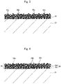
- FIG. 3 is a schematic enlarged cross-sectional view of a titanium substrate 31 and a carbon black layer 32 after the step S1 of forming the carbon black layer illustrated in FIG. 2 .
- the titanium substrate 31 in a plate shape is prepared, and the carbon black layer 32 is formed on a surface thereof.
- a plate-shaped titanium material made of a cold rolled material is prepared as the titanium substrate 31.
- the thickness of the titanium substrate 31 may be 0.05 to 1 mm, for example.
- the titanium substrate 31 is made of titanium or titanium alloy.
- titanium include types 1 to 4 (corresponding to grades 1 to 4 of ASTM) specified in the Japanese Industrial Standard H 4600.
- Examples of titanium alloy include Ti-Al, Ti-Nb, Ti-Ta, Ti-6Al-4 V, and Ti-Pd.
- the metal substrate may be a stainless steel substrate or the like as long as a carbon layer made of carbon can be formed (deposited) on the metal substrate as described below.
- a carbon black layer 32 is formed on the surface (planar surface) of the titanium substrate 31.
- the carbon black 32a is dried to form the carbon black layer 32.
- the carbon black 32a may be applied in a state in which the carbon black 32a is dispersed in a dispersion medium such as water or ethanol.
- a method of application coating using a roll coater, spray coating, or the like can be used. However, the method of application is not limited thereto as long as the carbon black layer 32 can be formed on the titanium substrate 31.
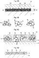
- FIG. 4 is a schematic enlarged cross-sectional view of the titanium substrate 31 and a carbon layer 35 after the step S2 of forming the mixture layer illustrated in FIG. 2 .
- heat treatment is performed on the titanium substrate 31 having formed thereon the carbon black layer 32 illustrated in FIG. 3 .
- titanium atoms are diffused from the surface of the titanium substrate 31 outward into the carbon black layer 32, and the titanium atoms diffused outward are caused to react with oxygen gas so as to generate titanium oxide 33. Consequently, a mixture layer 34 made of the carbon black 32a of the carbon black layer 32 and the titanium oxide 33 holding the carbon black 32a is formed as a part of the carbon layer 35 on the surface of the titanium substrate 31.
- the thickness of the mixture layer 34 may be in the range of 40 to 100 nm.
- the heat treatment for the titanium substrate 31 having the carbon black layer 32 formed thereon may be performed in a low oxygen atmosphere containing oxygen gas at an oxygen partial pressure of 1 to 100 Pa. If the oxygen partial pressure is less than 1 Pa, the titanium atoms cannot be oxidized sufficiently, and if the oxygen partial pressure is over 100 Pa, carbon dioxide may be generated by the reactions between carbon and oxygen.
- the heating temperature may be in the range of 550 to 700 °C.
- the heating time may be in the range of 5 to 60 seconds. Setting each of the heating temperature and the heating time to such a range can obtain the mixture layer 34 with a thickness that allows the titanium oxide 33 to sufficiently hold the carbon black 32a.
- the carbon layer 35 is formed of the mixture layer 34 in which the carbon black 32a is held by the titanium oxide 33, and redundant carbon black 32b stuck to the surface of the mixture layer 34.
- the redundant carbon black 32b is a part of the carbon black 32a of the carbon black layer 32 illustrated in FIG. 3 that is not held by the titanium oxide 33 as the titanium atoms diffused outward have not reached that part.
- the redundant carbon black 32b is removed in a subsequent step. It should be noted that if the redundant carbon black 32b is removed before a next step S3 of forming a resin layer, the carbon layer 35 described below is formed of the mixture layer 34.
- step S 1 of forming the carbon black layer and the step S2 of forming the mixture layer are performed in this embodiment, instead of such steps, the method described in Patent Literature 1 above may be used to form the carbon layer, and a carbon layer (or a carbon film) may be formed (or deposited) using plasma CVD, plasma PVD, or the like.
- a stainless steel substrate may be used as the metal substrate instead of the titanium substrate.
- FIG. 5A is a schematic enlarged cross-sectional view of the titanium substrate 31, the carbon layer 35, and a resin layer 9 after the step S3 of forming the resin layer illustrated in FIG. 2 .
- FIG. 5B is a schematic view illustrating the states of resin particles 9a, 9b and a dispersant 9c in a suspension 9A in the step S3 of forming the resin layer.
- FIG. 5C is a schematic cross-sectional view illustrating a state in which the suspension 9A is applied to the carbon layer 35.
- FIG. 5D is a schematic view illustrating the state of the dispersant 9c in the resin layer 9 after the suspension 9A illustrated in FIG. 5C is dried.
- the suspension 9A is prepared.
- the suspension 9A is obtained by dispersing in a liquid medium 9d the resin particles 9a, 9b made of thermoplastic resin as the base material of the resin layer 9.
- the suspension 9A also contains the dispersant 9c made of a fatty acid.
- the suspension 9A is applied to the surface of the carbon layer 35.
- the method of application of the suspension 9A may be any method such as, for example, roll coating, spin coating, dip coating, spray coating, die coating, ink jet printing, or gravure coating.
- the resin particles 9a, 9b are heated to a temperature of greater than or equal to the softening point thereof and the liquid medium 9d is dried so that the resin layer 9 is formed on the surface of the carbon layer 35.
- a separator material 3A including the titanium substrate 31, the carbon layer 35 covering the titanium substrate 31, and the resin layer 9 covering the carbon layer 35 can be obtained.
- the separator material 3A is in a plate shape, and is a material to be press-formed into the separator 3.
- the resin particles 9a, 9b, the dispersant 9c, and the liquid medium 9d contained in the suspension 9A will be described.
- thermoplastic resin may be the one that (1) becomes soft when heated and thus can form the resin layer 9, (2) can secure a sticking force between the resin layer 9 and the carbon layer 35, and does not peel off the carbon layer 35 (specifically, the mixture layer 34) during pressing forming described below, and (3) can be easily removed in removal of the resin layer 9 described below.
- thermoplastic resin examples include acrylic resin, vinyl resin, styrene resin, methyl methacrylate-styrene copolymer resin, polycarbonate resin, vinyl resin, polyolefin resin such as polyethylene or polypropylene, polyester resin, polyacetal resin, and nylon resin.
- thermoplastic resin can be used either alone or in combination of two or more.
- the resin particles 9a added to the suspension 9A are acrylic resin, and examples thereof include a homopolymer of (meth)acrylate ester, and a copolymer of (meth)acrylate ester and another monomer that can be copolymerized therewith.
- Specific examples of (meth)acrylate ester include methyl (meth)acrylate, ethyl (meth)acrylate, and isopropyl (meth)acrylate.
- Examples of another monomer that can be copolymerized with (meth)acrylate ester include unsaturated carboxylic acids such as (meth)acrylic acid, crotonic acid, maleic acid, fumaric acid, and itaconic acid.
- Acrylic resin has a high sticking force to carbon and titanium, and easily dissolves in a strong alkaline solvent when exposed thereto. Therefore, when acrylic resin is used for the resin particles 9a, peeling of the resin layer 9 can be suppressed in a press-forming step S4 described below, and the acrylic resin can dissolved using a strong alkaline solution in a step S5 of removing the resin layer.
- the resin particles 9b added to the suspension 9A are vinyl resin, for example, and are added as appropriate to the suspension 9A to secure the strength of the resin layer 9 in the press-forming step S4 described below.
- Vinyl resin is resin having a vinyl group, and examples thereof include polyvinyl chloride, polyvinyl acetate, polyvinylidene chloride, polyvinyl alcohol, and polyvinyl acetal.
- the resin particles 9b are added to the suspension 9A in this embodiment, the resin particles added to the suspension 9A may be only the resin particles 9a made of acrylic resin, for example, and further, a plurality of types of resin particles made of other types of the aforementioned thermoplastic resin may also be added.
- the dispersant 9c added to the suspension 9A may be a fatty acid that does not vaporize or decompose at the softening point of the thermoplastic resin forming the resin particles 9a, 9b.
- the fatty acid include a higher fatty acid with 12 to 24 carbon atoms, such as straight-chain saturated fatty acids including lauric acid, myristic acid, pentadecyl acid, palmitic acid, margaric acid, stearic acid, arachidic acid, behenic acid, and lignoceric acid.
- the fatty acid is adsorbed to the resin particles 9a made of acrylic resin and the resin particles 9b made of vinyl resin in the suspension 9A, and agglutinate around the resin particles 9a, 9b.
- the resin particles 9a, 9b can be dispersed in the suspension 9A.
- the dispersant 9c is dispersed in the resin layer 9 formed, and can be used as a lubricant in the press-forming step S4 described below.
- liquid medium 9d of the suspension 9A examples include water and alcohol, but are not particularly limited as long as the liquid medium 9d can vaporize at the softening point of thermoplastic resin forming the resin particles 9a, 9b. Further, the dispersant 9c need not be added if the resin particles 9a, 9b can be uniformly dispersed in the liquid medium 9d.
- the resin particles 9a, 9b can be dispersed on the surface of the carbon layer 35 as illustrated in FIG. 5C . Then, heating the resin particles 9a, 9b to a temperature of greater than or equal to the softening point thereof will allow a more uniform, thinner resin layer 9 to be formed over the carbon layer 35.
- the thickness of the resin layer 9 is in the range of 1 to 5 ⁇ m, for example.
- the resin layer 9 obtained through this step contains thermoplastic resin as a base material of the resin layer, and a lubricant (i.e., the dispersant 9c) dispersed in the resin layer 9, and the thermoplastic resin includes acrylic resin and vinyl resin. More specifically, the resin layer 9 is a layer in which thermoplastic resin forming the resin particles 9a, 9b is deposited by being granularly dispersed, and a fatty acid, which is the dispersant 9c, is dispersed as a lubricant in the resin layer 9, as illustrated in FIG. 5D .
- FIG. 6A is a cross-sectional view of a separator 3B after the press-forming step S4 illustrated in FIG. 2 .
- FIG. 6B is a schematic enlarged cross-sectional view of the separator 3B after the press forming illustrated in FIG. 6A .
- the separator material 3A after the step S3 of forming the resin layer is press-formed into the shape of the separator 3 such that gas flow channels 21A are formed thereon. At this time, cracks are generated in the carbon layer 35 of the separator 3B. However, since the carbon layer 35 is covered with the resin layer 9, there is no possibility that the carbon black 32a, 32b will be detached from the carbon layer 35.
- the carbon black 32a is likely to be detached from the carbon layer 35 during press forming.
- the resin layer 9 the redundant carbon black 32b on the surface of the mixture layer 34 is also likely to be detached from the carbon layer 35 during press forming, such detachment can also be avoided by the resin layer 9.
- the resin layer 9 of the separator material 3A contains acrylic resin with a high sticking force to carbon, titanium, and the like, peeling of the resin layer 9 off the carbon layer 35 can be suppressed during the press forming. Further, since the resin layer 9 contains a dispersant made of a fatty acid dispersed therein, the dispersant functions as a lubricant during the press forming, and thus, press formability can be enhanced.
- FIG. 7 is a schematic enlarged cross-sectional view of the separator 3 after the step S5 of removing the resin layer illustrated in FIG. 2 .
- This step can obtain the separator 3 by removing the resin layer 9 from the pressed-formed separator 3B.
- the resin layer 9 of the separator 3B is exposed to a strong alkaline solution with a pH of 9.6 to 13.8 for a predetermined time so that the resin layer 9 is removed.
- the strong alkaline solvent is an aqueous solution containing sodium carbonate as a main component, for example.
- the acrylic resin contained in the resin layer 9 dissolves in a strong alkaline solvent. Therefore, after the press forming, the resin layer 9 can be easily removed using a strong alkaline solvent without the separator 3 oxidized.
- the resin layer 9 contains vinyl resin in this embodiment, since the resin layer 9 also contains acrylic resin, the resin layer 9 is detached from the separator 3 due to the dissolution of the acrylic resin.
- the resin layer 9 Since the resin layer 9 is formed as a uniform, thin layer in the step S3 of forming the resin layer, the resin layer 9 can be removed from the carbon layer 35 in a short time. Since the redundant carbon black 32b remaining on the carbon layer 35 can be removed in removal of the resin layer 9, the redundant carbon black need not be removed before the press forming. Accordingly, the steps can be simplified.
- the solvent may be an organic solvent or the like as long as the resin layer 9 can be removed, and the resin layer 9 may be removed using plasma etching or the like.
- the redundant carbon black stuck to the surface of the mixture layer is removed in the step of removing the resin layer in the aforementioned embodiment
- the redundant carbon black may be removed after the step of forming the mixture layer and before the step of forming the resin layer, for example.
- the mixture layer may be formed such that redundant carbon black is not generated.
Landscapes
- Chemical & Material Sciences (AREA)
- Engineering & Computer Science (AREA)
- Chemical Kinetics & Catalysis (AREA)
- Electrochemistry (AREA)
- General Chemical & Material Sciences (AREA)
- Sustainable Development (AREA)
- Sustainable Energy (AREA)
- Life Sciences & Earth Sciences (AREA)
- Manufacturing & Machinery (AREA)
- Organic Chemistry (AREA)
- Materials Engineering (AREA)
- Nanotechnology (AREA)
- Inorganic Chemistry (AREA)
- Composite Materials (AREA)
- Fuel Cell (AREA)
- Mechanical Engineering (AREA)
- Metallurgy (AREA)
- Other Surface Treatments For Metallic Materials (AREA)
Abstract
Provided are a method for producing a fuel cell separator, and a separator material that can prevent carbon in a carbon layer formed on the surface of a metal substrate from being detached during press forming, and thus can suppress failures in the press forming. The method is a method for producing a fuel cell separator 3 having formed thereon gas flow channels 21, 22 through which fuel gas or oxidant gas to be supplied to a fuel cell stack 10 flows, the method including preparing a plate-shaped separator material 3A including a titanium substrate 31, a carbon layer 35 covering the titanium substrate 31, and a resin layer 9 covering the carbon layer 35; press-forming the prepared separator material 3A into the shape of the separator 3 such that the separator 3 has the gas flow channels 21, 22 formed thereon; and removing the resin layer 9 from the press-formed separator 3.
Description
- The present invention relates to a method for producing a fuel cell separator, and a separator material.
- A fuel cell stack has a plurality of stacked fuel cells, each including a solid polymer electrolyte membrane and anode and cathode electrodes sandwiching the solid polymer electrolyte membrane, as unit cells with separators interposed therebetween, each separator having formed thereon gas flow channels through which gas (e.g., hydrogen gas or oxidant gas) flows. Such a fuel cell separator has a role to cause current generated in the stack to flow through an adjacent cell, and therefore, a high conductive property and conductive durability are desired.
- As a method for producing a fuel cell separator, for example,
Patent Literature 1 discloses a method for producing a fuel cell separator that includes forming a coating layer containing carbon on the surface of a titanium substrate made of titanium or titanium alloy, and performing heat treatment on the titanium substrate, thereby forming a carbon layer on the surface of the titanium substrate. - Besides,
Patent Literature 2, for example, discloses a production method that includes coating the surface of a titanium substrate with carbon black so as to form a carbon black layer, and performing heat treatment on the coated substrate under a low-partial-oxygen-pressure atmosphere, thereby allowing titanium atoms in the substrate to diffuse outward into the carbon black layer. By such outward diffusion of titanium atoms, a mixture layer that contains the carbon black and titanium oxide holding the carbon black is formed. -
- Patent Literature 1:
JP 2014-146550 A - Patent Literature 2:
JP 2016-122642 A - A separator material produced with the production method described in
Patent Literature 1 or JPPatent Literature 2 as described above is further press-formed into the shape of a separator so that gas flow channels are formed thereon. During the press forming, carbon in the carbon layer formed on the metal substrate such as the titanium substrate may be detached in the form of particles or small pieces from the carbon layer. When the detached carbon sticks to a die and is accumulated on the die surface or sticks to a next separator material to be press-formed, there is a possibility that pressing defects may occur in the resulting separator. - The present invention has been made in view of the foregoing, and provides a method for producing a fuel cell separator, and a separator material that can prevent carbon in a carbon layer formed on the surface of a metal substrate from being detached during press forming, and thus can suppress failures in the press forming.
- Accordingly, the method for producing a fuel cell separator in accordance with the present invention is a method for producing a fuel cell separator, the fuel cell separator having formed thereon a gas flow channel through which one of fuel gas or oxidant gas to be supplied to a fuel cell flows, the method including: preparing a plate-shaped separator material including a metal substrate, a carbon layer covering the metal substrate, and a resin layer covering the carbon layer; press-forming the prepared separator material into the shape of the separator such that the separator has the gas flow channel formed thereon; and removing the resin layer from the pressed-formed separator.
- According to the present invention, since the carbon layer of the separator material is covered with the resin layer, even when cracks are generated in the carbon layer during press forming, the resin layer can prevent carbon in the carbon layer from being detached in the form of particles or small pieces from the carbon layer. Therefore, there is no possibility that carbon in the carbon layer will stick to a die. Consequently, pressing defects in the resulting separator due to sticking of carbon derived from the carbon layer to the die can be suppressed. Further, there is no need to apply excess machining oil to the die surface to suppress sticking of carbon in the carbon layer to the die. Therefore, since there is no possibility that the press forming of the separator will be disturbed due to the excess machining oil, the press-forming accuracy of the separator will not decrease.
- Herein, the materials of the carbon layer and the metal substrate of the prepared separator material are not particularly limited as long as the carbon layer has a sticking force to the surface of the metal substrate and the carbon layer and the metal substrate each have a conductive property, and the method for forming the carbon layer is not particularly limited, either. However, in some embodiments, the preparing may include preparing as the metal substrate a titanium substrate containing one of titanium or titanium alloy, and applying carbon black to the titanium substrate, thereby forming a carbon black layer, and performing heat treatment on the titanium substrate having the carbon black layer formed thereon, thereby diffusing titanium atoms from a surface of the titanium substrate into the carbon black layer, and thus forming a mixture layer as a part of the carbon layer on the surface of the titanium substrate, the mixture layer containing the carbon black of the carbon black layer and titanium oxide holding the carbon black.
- According to such a configuration of the separator material, the titanium substrate is covered with the carbon layer containing carbon black. Therefore, although the carbon black is likely to be detached from the carbon layer during press forming, such detachment can be avoided by the resin layer. Further, although redundant carbon black of the carbon black layer may remain on the surface of the mixture layer, and the redundant carbon black is also likely to be detached from the carbon layer during press forming, such detachment can also be avoided by the resin layer.
- Furthermore, since the redundant carbon black remaining on the mixture layer can be removed from the separator in removal of the resin layer, the redundant carbon black need not be removed before the press forming. Therefore, the steps can be simplified.
- Herein, the material of the resin layer covering the carbon layer of the prepared separator substrate is not particularly limited as long as detachment of carbon from the carbon layer can be prevented, and the method for forming the resin layer is not limited, either. However, in some embodiments, the preparing may include applying a suspension to a surface of the carbon layer, the suspension being obtained by dispersing in a liquid medium resin particles of thermoplastic resin as a base material of the resin layer, and heating the resin particles to a temperature of greater than or equal to the softening point of the resin particles and drying the liquid medium, thereby forming the resin layer on the surface of the carbon layer.
- According to such a configuration, as a suspension containing resin particles is applied to the surface of the carbon layer, the resin particles can be uniformly dispersed on the surface of the carbon layer. When the resin particles are heated to a temperature of greater than or equal to the softening point thereof, a more uniform, thinner resin layer can be formed over the carbon layer. Consequently, not only can the press-forming accuracy be enhanced, but also the resin layer can be removed from the carbon layer in a short time during the removal.
- Further, in some embodiments, the resin particles may include resin particles of acrylic resin, and the suspension may further contain a dispersant made of a fatty acid adapted to disperse the resin particles in the liquid medium.
- According to such a configuration, as the resin particles include resin particles of acrylic resin, the resin particles of acrylic resin can be dispersed in the suspension more uniformly by the dispersant made of a fatty acid. Accordingly, a more uniform, thinner resin layer can be formed over the carbon layer as described above. Since the acrylic resin contained in the resin layer has a high sticking force to carbon, titanium, and the like, the resin layer is unlikely to peel off the carbon layer during press forming. Further, since the dispersant made of a fatty acid is dispersed in the resin layer and functions as a lubricant during press forming, press formability can be enhanced. Furthermore, since the acrylic resin dissolves in a strong alkaline solvent, the resin layer can be easily removed using a strong alkaline solvent after the press forming without the separator oxidized.
- In this specification, a fuel cell separator material is also disclosed. A fuel cell separator material in accordance with the present invention is a fuel cell separator material in a plate shape, the fuel cell separator material being a material for a fuel cell separator having formed thereon a gas flow channel through which one of fuel gas or oxidant gas to be supplied to a fuel cell flows, the fuel cell separator material including: a metal substrate; a carbon layer covering the metal substrate; and a resin layer covering the carbon layer.
- According to the present invention, since the carbon layer of the separator material is covered with the resin layer, even when the separator material is press-formed into the shape of a separator and cracks are generated in the carbon layer, the resin layer can prevent carbon in the carbon layer from being detached in the form of particles or small pieces from the carbon layer. Therefore, there is no possibility that carbon in the carbon layer will stick to a die and the like. Consequently, pressing defects in the resulting separator due to sticking of carbon derived from the carbon layer to the die can be suppressed. Further, there is no need to apply excess machining oil to the die surface to suppress sticking of carbon in the carbon layer to the die. Therefore, since there is no possibility that the press forming of the separator will be disturbed due to the excess machining oil, the press-forming accuracy of the separator will not decrease.
- Herein, the materials of the carbon layer and the metal substrate of the prepared separator material are not particularly limited as long as the carbon layer has a sticking force to the surface of the metal substrate and the carbon layer and the metal substrate each have a conductive property. However, in some embodiments, the metal substrate may be a titanium substrate containing one of titanium or titanium alloy, and the carbon layer may include a mixture layer containing carbon black and titanium oxide holding the carbon black.
- Herein, the carbon layer formed over the titanium substrate of the separator material contains carbon black. Therefore, although the carbon black is likely to be detached from the carbon layer during press forming, the configuration herein can prevent such detachment of the carbon black from the carbon layer due to the presence of the resin layer.
- In some embodiments, the resin layer may contain thermoplastic resin as a base material of the resin layer and a lubricant dispersed in the resin layer; the thermoplastic resin may include acrylic resin; and the lubricant may be a fatty acid.
- According to such a configuration, since the acrylic resin contained in the resin layer has a high sticking force to carbon, titanium, and the like, the resin layer is unlikely to peel off the carbon layer during press forming. Further, since the lubricant made of a fatty acid is dispersed in the resin layer, press formability can be enhanced. Furthermore, since the acrylic resin dissolves in a strong alkaline solvent, the resin layer can be easily removed using a strong alkaline solvent after the press forming without the separator oxidized.
- According to the present invention, carbon in a carbon layer formed on the surface of a metal substrate can be prevented from being detached during press forming, and thus, failures in the press forming can be suppressed.
-
-
FIG. 1 a schematic cross-sectional view of the primary portion of a fuel cell stack including separators in accordance with an embodiment of the present invention; -
FIG. 2 is a flowchart for illustrating a method for producing the fuel cell separator illustrated inFIG. 1 ; -
FIG. 3 is a schematic enlarged cross-sectional view of a titanium substrate and a carbon black layer after a step of forming the carbon black layer illustrated inFIG. 2 ; -
FIG. 4 is a schematic enlarged cross-sectional view of the titanium substrate and the carbon layer after a step of forming a mixture layer illustrated inFIG. 2 ; -
FIG. 5A is a schematic enlarged cross-sectional view of the titanium substrate, the carbon layer, and a resin layer after a step of forming the resin layer illustrated inFIG. 2 ; -
FIG. 5B is a schematic view illustrating the states of resin particles and a dispersant in a suspension in the step of forming the resin layer; -
FIG. 5C is a schematic cross-sectional view illustrating a state in which a suspension is applied to the carbon layer; -
FIG. 5D is a schematic view illustrating the state of the dispersant in the resin layer after the suspension illustrated inFIG. 5C is dried; -
FIG. 6A is a cross-sectional view of the separator after a press-forming step illustrated inFIG. 2 ; -
FIG. 6B is a schematic enlarged cross-sectional view of the separator after the press-forming step illustrated inFIG. 6A ; and -
FIG. 7 is a schematic enlarged cross-sectional view of the separator after a step of removing the resin layer illustrated inFIG. 2 . - Hereinafter, the configuration of the present invention will be described in detail on the basis of exemplary embodiments illustrated in the accompanying drawings. Although the following embodiments illustrate examples in which the present invention is applied to a fuel cell stack or a fuel cell system including the fuel cell stack mounted on a fuel cell vehicle, the range of application of the present invention is not limited thereto.
-
FIG. 1 is a schematic cross-sectional view of the primary portion of afuel cell stack 10 includingseparators 3 in accordance with an embodiment of the present invention. As illustrated inFIG. 1 , the fuel cell stack (stacked fuel cells) 10 has a plurality of stacked cells (unit cells) 1. Eachcell 1 is a polymer electrolyte fuel cell that generates an electromotive force when an electrochemical reaction occurs between oxidant gas (for example, air) and fuel gas (for example, hydrogen gas). Thecell 1 includes a MEGA (Membrane Electrode & Gas Diffusion Layer Assembly) 2 and separators (fuel cell separators) 3 adapted to be in contact with theMEGA 2 so as to separate the MEGA (power generating portion) 2 from MEGAs 2 of adjacent fuel cells. It should be noted that in this embodiment, theMEGA 2 is sandwiched between a pair ofseparators - The
MEGA 2 is an integral structure of a membrane electrode assembly (MEA) 4 and gas diffusion layers 7, 7 arranged on opposite sides thereof. Themembrane electrode assembly 4 includes anelectrolyte membrane 5 and a pair ofelectrodes electrolyte membrane 5 therebetween. Theelectrolyte membrane 5 is a proton-conducting ion exchange membrane formed of a solid polymer material, and eachelectrode 6 is formed of a porous carbon material having a catalyst, such as platinum, carried thereon, for example. Theelectrode 6 arranged on one side of theelectrolyte membrane 5 serves as an anode, and theelectrode 6 on the other side serves as a cathode. Eachgas diffusion layer 7 is formed of a gas-permeable conductive member, such as a carbon porous body like carbon paper or carbon cloth, or a metal porous body like a metallic mesh or foam metal, for example. - In this embodiment, the
MEGA 2 is the power generation portion of thefuel cell stack 10, and theseparators 3 are in contact with thegas diffusion layers 7 of theMEGA 2. When thegas diffusion layers 7 are omitted, themembrane electrode assembly 4 is the power generation portion, and in such a case, theseparators 3 are in contact with themembrane electrode assembly 4. Therefore, the power generation portion of thefuel cell stack 10 includes themembrane electrode assembly 4 and is in contact with theseparators 3. Eachseparator 3 is a member made of metal with excellent conductivity, gas impermeability, and the like, such as titanium, titanium alloy, or stainless steel, as a base material, andcontact portions 3a on one side of theseparator 3 abut thegas diffusion layer 7 of theMEGA 2, andcontact portions 3b on the other side thereof abut one side of anadjacent separator 3. Thecontact portions MEGA 2 that is the power generating portion. - In this embodiment, each
separator 3 is formed in a wave shape. Specifically, theseparator 3 has such a shape that the shapes of waves form trapezoids with equal legs, the top portion of each wave is flat, and opposite ends of the top portion are angular with equal angles. The shapes of eachseparator 3 seen from the front side and the rear side are almost the same. The top portions (projections) of theseparator 3 are thecontact portions contact portions 3a that are the top portions of theseparator 3 are in surface contact with one of thegas diffusion layers 7 of theMEGA 2, and thecontact portions 3b that are the top portions of anotherseparator 3 are in surface contact with the othergas diffusion layer 7 of theMEGA 2. -
Gas flow channels 21 defined between thegas diffusion layer 7 on one electrode (that is, the anode) 6 side and theseparator 3 are channels through which fuel gas circulates, andgas flow channels 22 defined between thegas diffusion layer 7 on the other electrode (that is, the cathode) 6 side and theseparator 3 are channels through which oxidant gas circulates. When fuel gas is supplied to thegas flow channels 21 on one side and oxidant gas is supplied to thegas flow channels 22 on the side opposite thegas flow channels 21 with thecell 1 sandwiched therebetween, an electrochemical reaction occurs within thecell 1 so that an electromotive force is generated. - Further, two
adjacent cells 1 are arranged such that anelectrode 6 to serve as an anode and anelectrode 6 to serve as a cathode are arranged opposite each other. In addition,contact portions 3b on the rear surface side of aseparator 3, which is arranged along anelectrode 6 to serve as an anode of a givencell 1, andcontact portions 3b on the rear surface side of aseparator 3, which is arranged along anelectrode 6 to serve as a cathode of anothercell 1, are in surface contact with each other. Water as refrigerant for cooling thecells 1 circulates throughspaces 23 defined between theseparators adjacent cells 1. - A method for producing the
separator 3 in accordance with this embodiment will be described with reference toFIGS. 2 to 7 .FIG. 2 is a flowchart for illustrating the method for producing thefuel cell separator 3 illustrated inFIG. 1 . It should be noted that, while the following describes the method for producing theseparator 3 on which thegas flow channels 21 for fuel gas are formed, the method for producing theseparator 3 on which thegas flow channels 22 for oxidant gas are formed is similar, and thus, the detailed description will not be further elaborated here. - First, a step S1 of forming a carbon black layer illustrated in
FIG. 2 is performed.FIG. 3 is a schematic enlarged cross-sectional view of atitanium substrate 31 and acarbon black layer 32 after the step S1 of forming the carbon black layer illustrated inFIG. 2 . In this step, thetitanium substrate 31 in a plate shape is prepared, and thecarbon black layer 32 is formed on a surface thereof. - Specifically, first, a plate-shaped titanium material made of a cold rolled material is prepared as the
titanium substrate 31. The thickness of thetitanium substrate 31 may be 0.05 to 1 mm, for example. Thetitanium substrate 31 is made of titanium or titanium alloy. Examples of titanium includetypes 1 to 4 (corresponding togrades 1 to 4 of ASTM) specified in the Japanese Industrial Standard H 4600. Examples of titanium alloy include Ti-Al, Ti-Nb, Ti-Ta, Ti-6Al-4 V, and Ti-Pd. Although thetitanium substrate 31 is prepared as the metal substrate in this embodiment, the metal substrate may be a stainless steel substrate or the like as long as a carbon layer made of carbon can be formed (deposited) on the metal substrate as described below. - Next, a
carbon black layer 32 is formed on the surface (planar surface) of thetitanium substrate 31. Aftercarbon black 32a is applied to the surface of theprepared titanium substrate 31, thecarbon black 32a is dried to form thecarbon black layer 32. Thecarbon black 32a may be applied in a state in which thecarbon black 32a is dispersed in a dispersion medium such as water or ethanol. As a method of application, coating using a roll coater, spray coating, or the like can be used. However, the method of application is not limited thereto as long as thecarbon black layer 32 can be formed on thetitanium substrate 31. - Next, a step S2 of forming a mixture layer illustrated in
FIG. 2 is performed.FIG. 4 is a schematic enlarged cross-sectional view of thetitanium substrate 31 and acarbon layer 35 after the step S2 of forming the mixture layer illustrated inFIG. 2 . - In this step, heat treatment is performed on the
titanium substrate 31 having formed thereon thecarbon black layer 32 illustrated inFIG. 3 . By the heat treatment, titanium atoms are diffused from the surface of thetitanium substrate 31 outward into thecarbon black layer 32, and the titanium atoms diffused outward are caused to react with oxygen gas so as to generatetitanium oxide 33. Consequently, amixture layer 34 made of the carbon black 32a of thecarbon black layer 32 and thetitanium oxide 33 holding thecarbon black 32a is formed as a part of thecarbon layer 35 on the surface of thetitanium substrate 31. The thickness of themixture layer 34 may be in the range of 40 to 100 nm. - The heat treatment for the
titanium substrate 31 having thecarbon black layer 32 formed thereon may be performed in a low oxygen atmosphere containing oxygen gas at an oxygen partial pressure of 1 to 100 Pa. If the oxygen partial pressure is less than 1 Pa, the titanium atoms cannot be oxidized sufficiently, and if the oxygen partial pressure is over 100 Pa, carbon dioxide may be generated by the reactions between carbon and oxygen. The heating temperature may be in the range of 550 to 700 °C. The heating time may be in the range of 5 to 60 seconds. Setting each of the heating temperature and the heating time to such a range can obtain themixture layer 34 with a thickness that allows thetitanium oxide 33 to sufficiently hold thecarbon black 32a. - In this embodiment, the
carbon layer 35 is formed of themixture layer 34 in which thecarbon black 32a is held by thetitanium oxide 33, and redundant carbon black 32b stuck to the surface of themixture layer 34. The redundant carbon black 32b is a part of the carbon black 32a of thecarbon black layer 32 illustrated inFIG. 3 that is not held by thetitanium oxide 33 as the titanium atoms diffused outward have not reached that part. The redundant carbon black 32b is removed in a subsequent step. It should be noted that if the redundant carbon black 32b is removed before a next step S3 of forming a resin layer, thecarbon layer 35 described below is formed of themixture layer 34. - Although the
step S 1 of forming the carbon black layer and the step S2 of forming the mixture layer are performed in this embodiment, instead of such steps, the method described inPatent Literature 1 above may be used to form the carbon layer, and a carbon layer (or a carbon film) may be formed (or deposited) using plasma CVD, plasma PVD, or the like. In such a case, for example, a stainless steel substrate may be used as the metal substrate instead of the titanium substrate. - Next, the step S3 of forming a resin layer illustrated in
FIG. 2 is performed.FIG. 5A is a schematic enlarged cross-sectional view of thetitanium substrate 31, thecarbon layer 35, and aresin layer 9 after the step S3 of forming the resin layer illustrated inFIG. 2 . In addition,FIG. 5B is a schematic view illustrating the states ofresin particles dispersant 9c in asuspension 9A in the step S3 of forming the resin layer.FIG. 5C is a schematic cross-sectional view illustrating a state in which thesuspension 9A is applied to thecarbon layer 35.FIG. 5D is a schematic view illustrating the state of thedispersant 9c in theresin layer 9 after thesuspension 9A illustrated inFIG. 5C is dried. - In this step, first, the
suspension 9A is prepared. Thesuspension 9A is obtained by dispersing in a liquid medium 9d theresin particles resin layer 9. In this embodiment, thesuspension 9A also contains thedispersant 9c made of a fatty acid. Next, as illustrated inFIG. 5C , thesuspension 9A is applied to the surface of thecarbon layer 35. - The method of application of the
suspension 9A may be any method such as, for example, roll coating, spin coating, dip coating, spray coating, die coating, ink jet printing, or gravure coating. - Next, as illustrated in
FIGS. 5C and 5D , theresin particles resin layer 9 is formed on the surface of thecarbon layer 35. Accordingly, as illustrated inFIG. 5A , aseparator material 3A including thetitanium substrate 31, thecarbon layer 35 covering thetitanium substrate 31, and theresin layer 9 covering thecarbon layer 35 can be obtained. Theseparator material 3A is in a plate shape, and is a material to be press-formed into theseparator 3. Hereinafter, theresin particles dispersant 9c, and the liquid medium 9d contained in thesuspension 9A will be described. - In this embodiment, two types of the
resin particles resin layer 9, (2) can secure a sticking force between theresin layer 9 and thecarbon layer 35, and does not peel off the carbon layer 35 (specifically, the mixture layer 34) during pressing forming described below, and (3) can be easily removed in removal of theresin layer 9 described below. - Examples of such thermoplastic resin include acrylic resin, vinyl resin, styrene resin, methyl methacrylate-styrene copolymer resin, polycarbonate resin, vinyl resin, polyolefin resin such as polyethylene or polypropylene, polyester resin, polyacetal resin, and nylon resin. Such thermoplastic resin can be used either alone or in combination of two or more.
- In this embodiment, the
resin particles 9a added to thesuspension 9A are acrylic resin, and examples thereof include a homopolymer of (meth)acrylate ester, and a copolymer of (meth)acrylate ester and another monomer that can be copolymerized therewith. Specific examples of (meth)acrylate ester include methyl (meth)acrylate, ethyl (meth)acrylate, and isopropyl (meth)acrylate. Examples of another monomer that can be copolymerized with (meth)acrylate ester include unsaturated carboxylic acids such as (meth)acrylic acid, crotonic acid, maleic acid, fumaric acid, and itaconic acid. - Acrylic resin has a high sticking force to carbon and titanium, and easily dissolves in a strong alkaline solvent when exposed thereto. Therefore, when acrylic resin is used for the
resin particles 9a, peeling of theresin layer 9 can be suppressed in a press-forming step S4 described below, and the acrylic resin can dissolved using a strong alkaline solution in a step S5 of removing the resin layer. - The
resin particles 9b added to thesuspension 9A are vinyl resin, for example, and are added as appropriate to thesuspension 9A to secure the strength of theresin layer 9 in the press-forming step S4 described below. Vinyl resin is resin having a vinyl group, and examples thereof include polyvinyl chloride, polyvinyl acetate, polyvinylidene chloride, polyvinyl alcohol, and polyvinyl acetal. - In this embodiment, since vinyl resin is contained in the
resin layer 9, damages and the like to theresin layer 9 can be suppressed in the press-forming step S4 described below. Although theresin particles 9b are added to thesuspension 9A in this embodiment, the resin particles added to thesuspension 9A may be only theresin particles 9a made of acrylic resin, for example, and further, a plurality of types of resin particles made of other types of the aforementioned thermoplastic resin may also be added. - The
dispersant 9c added to thesuspension 9A may be a fatty acid that does not vaporize or decompose at the softening point of the thermoplastic resin forming theresin particles - When a fatty acid is used for the
dispersant 9c, as illustrated inFIG. 5B , the fatty acid is adsorbed to theresin particles 9a made of acrylic resin and theresin particles 9b made of vinyl resin in thesuspension 9A, and agglutinate around theresin particles resin particles suspension 9A. Further, thedispersant 9c is dispersed in theresin layer 9 formed, and can be used as a lubricant in the press-forming step S4 described below. - Examples of the liquid medium 9d of the
suspension 9A include water and alcohol, but are not particularly limited as long as the liquid medium 9d can vaporize at the softening point of thermoplastic resin forming theresin particles dispersant 9c need not be added if theresin particles - In this manner, when the
suspension 9A containing theresin particles carbon layer 35, theresin particles carbon layer 35 as illustrated inFIG. 5C . Then, heating theresin particles thinner resin layer 9 to be formed over thecarbon layer 35. In this embodiment, the thickness of theresin layer 9 is in the range of 1 to 5 µm, for example. - The
resin layer 9 obtained through this step contains thermoplastic resin as a base material of the resin layer, and a lubricant (i.e., thedispersant 9c) dispersed in theresin layer 9, and the thermoplastic resin includes acrylic resin and vinyl resin. More specifically, theresin layer 9 is a layer in which thermoplastic resin forming theresin particles dispersant 9c, is dispersed as a lubricant in theresin layer 9, as illustrated inFIG. 5D . - Next, the press-forming step S4 illustrated in
FIG. 2 is performed.FIG. 6A is a cross-sectional view of aseparator 3B after the press-forming step S4 illustrated inFIG. 2 .FIG. 6B is a schematic enlarged cross-sectional view of theseparator 3B after the press forming illustrated inFIG. 6A . - In this step, the
separator material 3A after the step S3 of forming the resin layer is press-formed into the shape of theseparator 3 such thatgas flow channels 21A are formed thereon. At this time, cracks are generated in thecarbon layer 35 of theseparator 3B. However, since thecarbon layer 35 is covered with theresin layer 9, there is no possibility that thecarbon black carbon layer 35. - Specifically, since the
titanium substrate 31 of theseparator material 3A is covered with thecarbon layer 35 containing thecarbon black 32a, thecarbon black 32a is likely to be detached from thecarbon layer 35 during press forming. However, such detachment can be avoided by theresin layer 9. In addition, although the redundant carbon black 32b on the surface of themixture layer 34 is also likely to be detached from thecarbon layer 35 during press forming, such detachment can also be avoided by theresin layer 9. - Consequently, there is no possibility that the
carbon black carbon layer 35 will stick to the die and the like. Accordingly, pressing defects in the resultingseparator 3B due to sticking of thecarbon black carbon layer 35 to the die can be suppressed. Further, there is no need to apply excess machining oil to the die surface to suppress sticking of thecarbon black carbon layer 35 to the die. Therefore, there is no possibility that the press-forming accuracy of theseparator 3B will decrease due to the excess machining oil. - In particular, in this embodiment, since the more uniform,
thinner resin layer 9 is formed over thecarbon layer 35 in the step S3 of forming the resin layer, the press-forming accuracy of theseparator 3B in the press forming can be enhanced. - In addition, since the
resin layer 9 of theseparator material 3A contains acrylic resin with a high sticking force to carbon, titanium, and the like, peeling of theresin layer 9 off thecarbon layer 35 can be suppressed during the press forming. Further, since theresin layer 9 contains a dispersant made of a fatty acid dispersed therein, the dispersant functions as a lubricant during the press forming, and thus, press formability can be enhanced. - Next, a step S5 of removing the resin layer illustrated in
FIG. 2 is performed.FIG. 7 is a schematic enlarged cross-sectional view of theseparator 3 after the step S5 of removing the resin layer illustrated inFIG. 2 . - This step can obtain the
separator 3 by removing theresin layer 9 from the pressed-formedseparator 3B. Specifically, in this embodiment, theresin layer 9 of theseparator 3B is exposed to a strong alkaline solution with a pH of 9.6 to 13.8 for a predetermined time so that theresin layer 9 is removed. The strong alkaline solvent is an aqueous solution containing sodium carbonate as a main component, for example. - As described above, the acrylic resin contained in the
resin layer 9 dissolves in a strong alkaline solvent. Therefore, after the press forming, theresin layer 9 can be easily removed using a strong alkaline solvent without theseparator 3 oxidized. Although theresin layer 9 contains vinyl resin in this embodiment, since theresin layer 9 also contains acrylic resin, theresin layer 9 is detached from theseparator 3 due to the dissolution of the acrylic resin. - Since the
resin layer 9 is formed as a uniform, thin layer in the step S3 of forming the resin layer, theresin layer 9 can be removed from thecarbon layer 35 in a short time. Since the redundant carbon black 32b remaining on thecarbon layer 35 can be removed in removal of theresin layer 9, the redundant carbon black need not be removed before the press forming. Accordingly, the steps can be simplified. - Although the
resin layer 9 is dissolved using a strong alkaline solvent in this embodiment, the solvent may be an organic solvent or the like as long as theresin layer 9 can be removed, and theresin layer 9 may be removed using plasma etching or the like. - Although the illustrative embodiments of the present invention have been described in detail above, the present invention is not limited thereto, and various design changes can be made within the spirit and scope of the present invention recited in the appended claims.
- For example, although the redundant carbon black stuck to the surface of the mixture layer is removed in the step of removing the resin layer in the aforementioned embodiment, the redundant carbon black may be removed after the step of forming the mixture layer and before the step of forming the resin layer, for example. Alternatively, in the step of forming the mixture layer, the mixture layer may be formed such that redundant carbon black is not generated.
-
- 10
- Fuel cell stack
- 3
- Separator
- 3A
- Separator material
- 3B
- Separator
- 9
- Resin layer
- 9A
- Suspension
- 9a, 9b
- Resin particles
- 9c
- Dispersant (lubricant)
- 9d
- Liquid medium
- 21, 22
- Gas flow channels
- 31
- Titanium substrate (metal substrate)
- 32
- Carbon black layer
- 32a
- Carbon black
- 32b
- Redundant carbon black
- 33
- Titanium oxide
- 34
- Mixture layer
- 35
- Carbon layer
Claims (7)
- A method for producing a fuel cell separator, the fuel cell separator having formed thereon a gas flow channel through which one of fuel gas or oxidant gas to be supplied to a fuel cell flows, the method comprising:preparing a plate-shaped separator material including a metal substrate, a carbon layer covering the metal substrate, and a resin layer covering the carbon layer;press-forming the prepared separator material into a shape of the separator such that the separator has the gas flow channel formed thereon; andremoving the resin layer from the press-formed separator.
- The method for producing the fuel cell separator according to claim 1,
wherein the preparing includespreparing as the metal substrate a titanium substrate containing one of titanium or titanium alloy, and applying carbon black to the titanium substrate, thereby forming a carbon black layer, andperforming heat treatment on the titanium substrate having the carbon black layer formed thereon, thereby diffusing titanium atoms from a surface of the titanium substrate into the carbon black layer, and thus forming a mixture layer as a part of the carbon layer on the surface of the titanium substrate, the mixture layer containing the carbon black of the carbon black layer and titanium oxide holding the carbon black. - The method for producing the fuel cell separator according to claim 1 or 2,
wherein the preparing includes applying a suspension to a surface of the carbon layer, the suspension being obtained by dispersing in a liquid medium resin particles of thermoplastic resin as a base material of the resin layer, and heating the resin particles to a temperature of greater than or equal to a softening point of the resin particles and drying the liquid medium, thereby forming the resin layer on the surface of the carbon layer. - The method for producing the fuel cell separator according to claim 3,
wherein:the resin particles include resin particles of acrylic resin, andthe suspension further contains a dispersant made of a fatty acid adapted to disperse the resin particles in the liquid medium. - A fuel cell separator material in a plate shape, the fuel cell separator material being a material for a fuel cell separator having formed thereon a gas flow channel through which one of fuel gas or oxidant gas to be supplied to a fuel cell flows, the fuel cell separator material comprising:a metal substrate;a carbon layer covering the metal substrate; anda resin layer covering the carbon layer.
- The fuel cell separator material according to claim 5,
wherein:the metal substrate is a titanium substrate containing one of titanium or titanium alloy, andthe carbon layer includes a mixture layer containing carbon black and titanium oxide holding the carbon black. - The fuel cell separator material according to claim 5 or 6,
wherein:the resin layer contains thermoplastic resin as a base material of the resin layer, and a lubricant dispersed in the resin layer,the thermoplastic resin includes acrylic resin, andthe lubricant is a fatty acid.
Applications Claiming Priority (1)
| Application Number | Priority Date | Filing Date | Title |
|---|---|---|---|
| JP2017244367A JP6973029B2 (en) | 2017-12-20 | 2017-12-20 | Manufacturing method of separator for fuel cell and separator material |
Publications (1)
| Publication Number | Publication Date |
|---|---|
| EP3503251A1 true EP3503251A1 (en) | 2019-06-26 |
Family
ID=64664114
Family Applications (1)
| Application Number | Title | Priority Date | Filing Date |
|---|---|---|---|
| EP18211249.0A Withdrawn EP3503251A1 (en) | 2017-12-20 | 2018-12-10 | Method for producing fuel cell separator, and separator material |
Country Status (6)
| Country | Link |
|---|---|
| US (1) | US10923736B2 (en) |
| EP (1) | EP3503251A1 (en) |
| JP (1) | JP6973029B2 (en) |
| KR (2) | KR102297678B1 (en) |
| CN (1) | CN110010919B (en) |
| CA (1) | CA3028108C (en) |
Families Citing this family (8)
| Publication number | Priority date | Publication date | Assignee | Title |
|---|---|---|---|---|
| JP7256103B2 (en) * | 2019-10-21 | 2023-04-11 | トヨタ自動車株式会社 | Separator and separator manufacturing method |
| WO2021157252A1 (en) | 2020-02-06 | 2021-08-12 | Nok株式会社 | Gasket with integrated separator, and manufacturing method thereof |
| JP2022073337A (en) * | 2020-10-30 | 2022-05-17 | 本田技研工業株式会社 | Fuel cell separator and manufacturing method of fuel cell separator |
| CN113066995B (en) * | 2021-03-23 | 2022-03-08 | 中国科学院化学研究所 | PEM fuel cell, high-toughness porous carbon paper and preparation method thereof |
| KR20230164005A (en) * | 2021-03-29 | 2023-12-01 | 도소 가부시키가이샤 | Thermoplastic resin, thermosetting resin, dispersion liquid composition, laminate for solid polymer fuel cell, method for producing the laminate for solid polymer fuel cell |
| JP7658940B2 (en) * | 2022-08-25 | 2025-04-08 | トヨタ自動車株式会社 | Fuel cell separator material, method for producing fuel cell separator using same, and fuel cell separator |
| KR102881248B1 (en) * | 2023-02-02 | 2025-11-05 | 현대제철 주식회사 | Metal separator and method for manufacturing the same |
| KR20250146098A (en) * | 2024-03-29 | 2025-10-13 | 현대제철 주식회사 | Method for manufacturing metal separator and metal separator manufactured therefrom |
Citations (3)
| Publication number | Priority date | Publication date | Assignee | Title |
|---|---|---|---|---|
| JP2014146550A (en) | 2013-01-30 | 2014-08-14 | Kobe Steel Ltd | Material for fuel cell separator and method for producing the same |
| JP2016122642A (en) | 2014-05-28 | 2016-07-07 | 株式会社神戸製鋼所 | Separator material for fuel cell and manufacturing method thereof |
| US20160268611A1 (en) * | 2013-11-11 | 2016-09-15 | Kabushiki Kaisha Kobe Seiko Sho (Kobe Steel, Ltd.) | Titanium separator material for fuel cells, and method for producing titanium separator material for fuel cells |
Family Cites Families (10)
| Publication number | Priority date | Publication date | Assignee | Title |
|---|---|---|---|---|
| DE60016295T2 (en) * | 1999-02-16 | 2005-05-04 | Nichias Corp. | resin composition |
| JP4743356B2 (en) * | 2000-05-15 | 2011-08-10 | 日清紡ホールディングス株式会社 | Manufacturing method of fuel cell separator, fuel cell separator, and polymer electrolyte fuel cell |
| JP2002235039A (en) * | 2001-02-08 | 2002-08-23 | Mitsubishi Electric Corp | Bright non-aqueous dispersion powder coating composition |
| EP2048731B1 (en) * | 2007-10-11 | 2010-08-25 | Nichias Corporation | Resin composition for fuel cell separator and fuel cell separator manufactured therefrom |
| JP2012160406A (en) | 2011-02-02 | 2012-08-23 | Shin Etsu Polymer Co Ltd | Hydrophilic separator, and method of manufacturing the same |
| JP6170477B2 (en) | 2013-11-11 | 2017-07-26 | 株式会社神戸製鋼所 | Titanium fuel cell separator material and method for producing titanium fuel cell separator material |
| JP5968857B2 (en) * | 2013-11-11 | 2016-08-10 | 株式会社神戸製鋼所 | Method for producing titanium fuel cell separator |
| CN106165169A (en) | 2014-04-03 | 2016-11-23 | 新日铁住金株式会社 | Fuel cell separator part composite metallic material, fuel cell separator part, fuel cell and, the manufacture method of fuel cell separator part composite metallic material |
| JP6753165B2 (en) * | 2015-07-01 | 2020-09-09 | 日本製鉄株式会社 | Titanium material for separators of polymer electrolyte fuel cells, and separators using it |
| JP6557275B2 (en) * | 2017-04-28 | 2019-08-07 | 積水化成品工業株式会社 | Acrylic resin particles and external preparations using the same |
-
2017
- 2017-12-20 JP JP2017244367A patent/JP6973029B2/en active Active
-
2018
- 2018-12-06 US US16/211,357 patent/US10923736B2/en active Active
- 2018-12-10 EP EP18211249.0A patent/EP3503251A1/en not_active Withdrawn
- 2018-12-14 KR KR1020180161717A patent/KR102297678B1/en active Active
- 2018-12-19 CN CN201811553673.4A patent/CN110010919B/en active Active
- 2018-12-19 CA CA3028108A patent/CA3028108C/en active Active
-
2020
- 2020-11-03 KR KR1020200145146A patent/KR20200127951A/en not_active Withdrawn
Patent Citations (4)
| Publication number | Priority date | Publication date | Assignee | Title |
|---|---|---|---|---|
| JP2014146550A (en) | 2013-01-30 | 2014-08-14 | Kobe Steel Ltd | Material for fuel cell separator and method for producing the same |
| US20150325863A1 (en) * | 2013-01-30 | 2015-11-12 | Kabushiki Kaisha Kobe Seiko Sho (Kobe Steel, Ltd.) | Material for fuel cell separators and method for producing same |
| US20160268611A1 (en) * | 2013-11-11 | 2016-09-15 | Kabushiki Kaisha Kobe Seiko Sho (Kobe Steel, Ltd.) | Titanium separator material for fuel cells, and method for producing titanium separator material for fuel cells |
| JP2016122642A (en) | 2014-05-28 | 2016-07-07 | 株式会社神戸製鋼所 | Separator material for fuel cell and manufacturing method thereof |
Also Published As
| Publication number | Publication date |
|---|---|
| JP6973029B2 (en) | 2021-11-24 |
| KR102297678B1 (en) | 2021-09-06 |
| KR20200127951A (en) | 2020-11-11 |
| US20190190036A1 (en) | 2019-06-20 |
| CN110010919B (en) | 2022-02-22 |
| KR20190074968A (en) | 2019-06-28 |
| JP2019114326A (en) | 2019-07-11 |
| US10923736B2 (en) | 2021-02-16 |
| CA3028108A1 (en) | 2019-06-20 |
| CN110010919A (en) | 2019-07-12 |
| CA3028108C (en) | 2021-05-11 |
Similar Documents
| Publication | Publication Date | Title |
|---|---|---|
| US10923736B2 (en) | Method for producing fuel cell separator, and separator material | |
| EP2251923A1 (en) | Method for manufacturing membrane electrode assembly for solid polymer fuel cell | |
| US9325017B2 (en) | Method for controlling ionomer and platinum distribution in a fuel cell electrode | |
| JP2008016431A (en) | Manufacturing method of membrane electrode assembly for polymer electrolyte fuel cell | |
| US11069905B2 (en) | Fuel cell separator | |
| JP4348155B2 (en) | Catalyst membrane for polymer electrolyte fuel cell, production method thereof and fuel cell using the same | |
| JP4501342B2 (en) | Method for producing separator of polymer electrolyte fuel cell | |
| CN107210467A (en) | The manufacture method of membrane electrode assembly | |
| TWI223466B (en) | Polymer electrolyte fuel cell which is improved its performance and reliability and manufacturing method of the same | |
| US11552318B2 (en) | Method of manufacturing electricity-generating assembly | |
| US20080178991A1 (en) | Method of making membrane electrode assemblies | |
| CA2649903A1 (en) | Methods of making components for electrochemical cells | |
| JP4348154B2 (en) | Catalyst membrane for polymer electrolyte fuel cell, production method thereof and fuel cell using the same | |
| JP5720321B2 (en) | Manufacturing method of gas diffusion electrode | |
| US20080248358A1 (en) | Polymer electrolyte fuel cell and production method thereof | |
| JP2013109950A (en) | Manufacturing method for membrane electrode assembly for polymer electrolyte fuel cell and membrane electrode assembly for polymer electrolyte fuel cell | |
| JP4787474B2 (en) | Method for producing laminated film for membrane-electrode assembly | |
| JP2009129667A (en) | Fuel cell | |
| JP6048015B2 (en) | Manufacturing method of membrane electrode assembly | |
| JP2010251033A (en) | Membrane / catalyst assembly manufacturing method, membrane / catalyst assembly and fuel cell | |
| JP2008047333A (en) | Manufacturing method of electrolyte membrane and manufacturing method of membrane electrode structure | |
| JP2024002714A (en) | Method for manufacturing fuel cell assembly | |
| JP2014067539A (en) | Method of producing membrane electrode assembly for fuel cell and solid polymer fuel cell | |
| JP2009272136A (en) | Method of manufacturing electrode for fuel cell, method of manufacturing membrane-electrode assembly for fuel cell, and fuel cell | |
| JP2009064723A (en) | Method for producing fuel cell catalyst layer and / or diffusion layer, produced fuel cell catalyst layer and / or diffusion layer, and method for producing fuel cell membrane electrode assembly |
Legal Events
| Date | Code | Title | Description |
|---|---|---|---|
| PUAI | Public reference made under article 153(3) epc to a published international application that has entered the european phase |
Free format text: ORIGINAL CODE: 0009012 |
|
| STAA | Information on the status of an ep patent application or granted ep patent |
Free format text: STATUS: REQUEST FOR EXAMINATION WAS MADE |
|
| 17P | Request for examination filed |
Effective date: 20181210 |
|
| AK | Designated contracting states |
Kind code of ref document: A1 Designated state(s): AL AT BE BG CH CY CZ DE DK EE ES FI FR GB GR HR HU IE IS IT LI LT LU LV MC MK MT NL NO PL PT RO RS SE SI SK SM TR |
|
| AX | Request for extension of the european patent |
Extension state: BA ME |
|
| STAA | Information on the status of an ep patent application or granted ep patent |
Free format text: STATUS: THE APPLICATION HAS BEEN WITHDRAWN |
|
| 18W | Application withdrawn |
Effective date: 20220810 |