EP3503229A1 - Intercooler provided with a thermoelectric generator for a turbocharged internal combustion engine - Google Patents
Intercooler provided with a thermoelectric generator for a turbocharged internal combustion engine Download PDFInfo
- Publication number
- EP3503229A1 EP3503229A1 EP18214934.4A EP18214934A EP3503229A1 EP 3503229 A1 EP3503229 A1 EP 3503229A1 EP 18214934 A EP18214934 A EP 18214934A EP 3503229 A1 EP3503229 A1 EP 3503229A1
- Authority
- EP
- European Patent Office
- Prior art keywords
- thermoelectric
- intercooler
- exchanger plate
- cells
- thermoelectric cell
- Prior art date
- Legal status (The legal status is an assumption and is not a legal conclusion. Google has not performed a legal analysis and makes no representation as to the accuracy of the status listed.)
- Granted
Links
Images



Classifications
-
- F—MECHANICAL ENGINEERING; LIGHTING; HEATING; WEAPONS; BLASTING
- F02—COMBUSTION ENGINES; HOT-GAS OR COMBUSTION-PRODUCT ENGINE PLANTS
- F02B—INTERNAL-COMBUSTION PISTON ENGINES; COMBUSTION ENGINES IN GENERAL
- F02B29/00—Engines characterised by provision for charging or scavenging not provided for in groups F02B25/00, F02B27/00 or F02B33/00 - F02B39/00; Details thereof
- F02B29/04—Cooling of air intake supply
- F02B29/0481—Intake air cooling by means others than heat exchangers, e.g. by rotating drum regenerators, cooling by expansion or by electrical means
-
- F—MECHANICAL ENGINEERING; LIGHTING; HEATING; WEAPONS; BLASTING
- F02—COMBUSTION ENGINES; HOT-GAS OR COMBUSTION-PRODUCT ENGINE PLANTS
- F02B—INTERNAL-COMBUSTION PISTON ENGINES; COMBUSTION ENGINES IN GENERAL
- F02B29/00—Engines characterised by provision for charging or scavenging not provided for in groups F02B25/00, F02B27/00 or F02B33/00 - F02B39/00; Details thereof
- F02B29/04—Cooling of air intake supply
- F02B29/0406—Layout of the intake air cooling or coolant circuit
- F02B29/0437—Liquid cooled heat exchangers
- F02B29/0443—Layout of the coolant or refrigerant circuit
-
- F—MECHANICAL ENGINEERING; LIGHTING; HEATING; WEAPONS; BLASTING
- F02—COMBUSTION ENGINES; HOT-GAS OR COMBUSTION-PRODUCT ENGINE PLANTS
- F02B—INTERNAL-COMBUSTION PISTON ENGINES; COMBUSTION ENGINES IN GENERAL
- F02B29/00—Engines characterised by provision for charging or scavenging not provided for in groups F02B25/00, F02B27/00 or F02B33/00 - F02B39/00; Details thereof
- F02B29/04—Cooling of air intake supply
- F02B29/045—Constructional details of the heat exchangers, e.g. pipes, plates, ribs, insulation, materials, or manufacturing and assembly
- F02B29/0462—Liquid cooled heat exchangers
-
- F—MECHANICAL ENGINEERING; LIGHTING; HEATING; WEAPONS; BLASTING
- F02—COMBUSTION ENGINES; HOT-GAS OR COMBUSTION-PRODUCT ENGINE PLANTS
- F02G—HOT GAS OR COMBUSTION-PRODUCT POSITIVE-DISPLACEMENT ENGINE PLANTS; USE OF WASTE HEAT OF COMBUSTION ENGINES; NOT OTHERWISE PROVIDED FOR
- F02G5/00—Profiting from waste heat of combustion engines, not otherwise provided for
-
- F—MECHANICAL ENGINEERING; LIGHTING; HEATING; WEAPONS; BLASTING
- F02—COMBUSTION ENGINES; HOT-GAS OR COMBUSTION-PRODUCT ENGINE PLANTS
- F02M—SUPPLYING COMBUSTION ENGINES IN GENERAL WITH COMBUSTIBLE MIXTURES OR CONSTITUENTS THEREOF
- F02M31/00—Apparatus for thermally treating combustion-air, fuel, or fuel-air mixture
- F02M31/20—Apparatus for thermally treating combustion-air, fuel, or fuel-air mixture for cooling
-
- H—ELECTRICITY
- H10—SEMICONDUCTOR DEVICES; ELECTRIC SOLID-STATE DEVICES NOT OTHERWISE PROVIDED FOR
- H10N—ELECTRIC SOLID-STATE DEVICES NOT OTHERWISE PROVIDED FOR
- H10N10/00—Thermoelectric devices comprising a junction of dissimilar materials, i.e. devices exhibiting Seebeck or Peltier effects
- H10N10/10—Thermoelectric devices comprising a junction of dissimilar materials, i.e. devices exhibiting Seebeck or Peltier effects operating with only the Peltier or Seebeck effects
- H10N10/13—Thermoelectric devices comprising a junction of dissimilar materials, i.e. devices exhibiting Seebeck or Peltier effects operating with only the Peltier or Seebeck effects characterised by the heat-exchanging means at the junction
-
- H—ELECTRICITY
- H10—SEMICONDUCTOR DEVICES; ELECTRIC SOLID-STATE DEVICES NOT OTHERWISE PROVIDED FOR
- H10N—ELECTRIC SOLID-STATE DEVICES NOT OTHERWISE PROVIDED FOR
- H10N10/00—Thermoelectric devices comprising a junction of dissimilar materials, i.e. devices exhibiting Seebeck or Peltier effects
- H10N10/10—Thermoelectric devices comprising a junction of dissimilar materials, i.e. devices exhibiting Seebeck or Peltier effects operating with only the Peltier or Seebeck effects
- H10N10/17—Thermoelectric devices comprising a junction of dissimilar materials, i.e. devices exhibiting Seebeck or Peltier effects operating with only the Peltier or Seebeck effects characterised by the structure or configuration of the cell or thermocouple forming the device
-
- Y—GENERAL TAGGING OF NEW TECHNOLOGICAL DEVELOPMENTS; GENERAL TAGGING OF CROSS-SECTIONAL TECHNOLOGIES SPANNING OVER SEVERAL SECTIONS OF THE IPC; TECHNICAL SUBJECTS COVERED BY FORMER USPC CROSS-REFERENCE ART COLLECTIONS [XRACs] AND DIGESTS
- Y02—TECHNOLOGIES OR APPLICATIONS FOR MITIGATION OR ADAPTATION AGAINST CLIMATE CHANGE
- Y02T—CLIMATE CHANGE MITIGATION TECHNOLOGIES RELATED TO TRANSPORTATION
- Y02T10/00—Road transport of goods or passengers
- Y02T10/10—Internal combustion engine [ICE] based vehicles
- Y02T10/12—Improving ICE efficiencies
Definitions
- the present invention relates to an intercooler provided with a thermoelectric generator (also called " TEG ”) for a turbocharged internal combustion heat engine.
- TEG thermoelectric generator
- thermoelectric cells In the constant effort to increase the energy efficiency of internal heat engines, it has recently been proposed to use part of the heat of the exhaust gases (which would otherwise be completely dispersed into the atmosphere through the exhaust system) to generate electrical energy through the use of thermoelectric cells.
- thermoelectric cell is able to convert heat into electrical energy (through the Seebeck, Peltier and Thomson effect) when there is a difference in temperature between its hot side and its cold side; in order to ensure effective generation of electrical energy, it is necessary to ensure that the temperature of the cold side of the thermoelectric cell remains sufficiently lower than the temperature of the hot side, and it is therefore necessary to provide constant cooling of the cold side.
- thermoelectric generator provided with a plurality of solid-state thermoelectric cells, each having a hot side that is exposed to the exhaust gases and heated by the exhaust gases themselves (which may have a temperature of 250-750°C depending on the area of the exhaust system in which the thermoelectric generator is arranged) and a cold side (opposite the hot side) that is constantly cooled by a cooling fluid (which is maintained strictly separated from the exhaust gases and generally consists of water that transfers heat to the external environment also by circulating through a radiator).
- thermoelectric generators for an exhaust system of an internal combustion engine.
- thermoelectric generator along the exhaust system allows the overall energy efficiency of the internal combustion engine to be increased; however, on the other hand, the integration of a thermoelectric generator along the exhaust system has several drawbacks as it significantly increases the cost (both because of the need to purchase special thermoelectric cells capable of withstanding the high temperatures of the exhaust gases and the chemical attack by the substances in the exhaust gases, and the need to create a liquid cooling system not otherwise present in the exhaust system), the overall dimensions and the weight (essentially due to the need to create a liquid cooling system not otherwise present in the exhaust system).
- Patent applications DE102008051843A1 and DE102012217215A1 describe an intercooler provided with a thermoelectric generator for a turbocharged internal combustion heat engine; in particular, the intercooler comprises a plurality of thermoelectric cells, each having a cold side resting on an exchanger plate, which is internally run through by a cooling fluid, and a hot side licked by the air sucked in.
- the object of the present invention is to provide an intercooler provided with a thermoelectric generator for a turbocharged internal combustion heat engine, which intercooler allows the overall energy efficiency of the internal combustion engine to be increased, and at the same time is easy and inexpensive to manufacture.
- thermoelectric generator for a turbocharged internal combustion heat engine
- number 1 indicates as a whole an internal combustion heat engine, which is provided with a drive shaft 2 for transmitting motion to the drive wheels of a vehicle.
- the internal combustion heat engine 1 comprises four cylinders 3, each of which is connected to an intake manifold 4 via at least one respective intake valve (not shown) and to an exhaust manifold 5 via at least one respective exhaust valve (not shown).
- Each cylinder 3 houses, on the inside, a respective piston that slides with reciprocating motion and is mechanically connected to the drive shaft 2; moreover, each cylinder 3 is provided with its own injector which injects the fuel directly inside the cylinder 3.
- the intake manifold 4 receives fresh air (i.e. air from the external environment) through an intake pipe 6, which is provided with an air filter 7 and is controlled by a throttle valve 8 (i.e. the throttle valve 8 adjusts the flow rate of fresh air fed by the intake pipe 6 to the intake manifold 4).
- An intercooler 9 i.e. a water-air heat exchanger
- the exhaust manifold 5 is connected to an exhaust pipe 10 that feeds the exhaust gases produced by combustion to an exhaust system, which emits the gases produced by combustion into the atmosphere and normally comprises at least one catalyst 11 and at least one silencer (not shown) arranged downstream of the catalyst 11.
- the internal combustion heat engine 1 is supercharged by a turbocharger supercharging system 12 comprising a turbocharger 13 provided with a turbine 14, which is arranged along the exhaust pipe 10 so as to rotate at high speed under the thrust of the exhaust gases expelled by the cylinders 3, and a compressor 15, which is rotated by the turbine 14 and arranged along the intake pipe 6 (upstream of the intercooler 9) so as to increase the pressure of the air fed by the intake pipe 6.
- the supercharging system 12 may also comprise an electric machine, which is mechanically connected to the shaft of the turbocharger 13 (i.e. is mechanically connected to the turbine 14 and the compressor 15) and reversible (i.e. it can be operated as an electric motor to absorb electrical energy and produce a mechanical torque or as an electrical generator to absorb mechanical energy and produce electrical energy).
- the intercooler 9 is integrated with the intake manifold 4 (i.e., it forms a single body with the intake manifold 4) and comprises a parallelepipedal box-like body 16 having an air inlet opening 17 and an air outlet opening 18, opposite and facing each other (i.e. the inlet opening 17 and the outlet opening 18 are formed through opposite and parallel walls of the box-like body 16).
- a cooling chamber 19 is defined inside the box-like body 16, the former being delimited on two opposite sides by the openings 17 and 18 and, in use, run through by a flow of air coming from the compressor 15 of the turbocharger 13 and directed toward the intake manifold 4.
- the intercooler 9 comprises a plurality of exchanger plates 20, which are stacked on top of one another inside the cooling chamber 19, are arranged parallel to an air flowing direction D from the inlet opening 17 to the outlet opening 18, are spaced apart from one another so as to define corresponding air passage channels between one another, and are internally hollow (that is, internally they have at least one channel, one chamber).
- the intercooler 9 comprises a circulation circuit 21, which allows a cooling fluid (typically water, optionally added with anti-freeze additives and/or anti-corrosion additives) to circulate inside the exchanger plates 20 (i.e. within the channels or chambers formed on the inside of the exchanger plates 20).
- a circulation path for the cooling fluid extending between an inlet opening 22 and an outlet opening 23, is defined inside each exchanger plate 20.
- the openings 22 and 23 of all the exchanger plates 20 are mutually aligned and superimposed so as to define respective channels that are connected to the remaining part of the circulation circuit 21, which is arranged outside the box-like body 16 (i.e. the cooling chamber 19) and generally comprising a circulation pump and a radiator (i.e. an air-water heat exchanger).
- the intercooler 9 comprises a plurality of solid-state thermoelectric cells 24, each of which has a substantially parallelepiped shape, is mounted on a corresponding exchanger plate 20, and has a cold side resting on the exchanger plate 20 and a hot side delimiting a corresponding air passage channel.
- Each thermoelectric cell 24 is able to convert heat into electrical energy (through the Seebeck, Peltier and Thomson effect) when there is a difference in temperature between its own hot side and its own cold side; in order to ensure effective generation of electrical energy, it is necessary to ensure that the temperature of the cold side of each thermoelectric cell 24 remains sufficiently lower than the temperature of the hot side, and it is therefore necessary to provide both constant heating to the hot side (through the intake air heated by the compressor 15 of the turbocharger 13), and constant cooling to the cold side (through the circulation of the cooling fluid inside the exchanger plates 20).
- thermoelectric generator i.e. a device that is able to convert part of the heat of the air into electrical energy and is also called "TEG" .
- each exchanger plate 20 comprises a plurality of pockets 25 (in particular, eight pockets 25), each of which has a parallelepiped shape, reproduces in negative the shape of a corresponding thermoelectric cell 24, and houses therein the thermoelectric cell 24, surrounding said thermoelectric cell 24 on five sides.
- each exchanger plate 20 comprises a plurality of seats, parallelepipedal cavities (i.e. the pockets 25), which reproduce in negative the shape of the thermoelectric cells 24 and house said thermoelectric cells 24.
- each pocket 25 has a rectangular-shaped bottom wall which is arranged in direct contact with the cold side of the corresponding thermoelectric cell 24 and a side wall, which projects perpendicularly from the bottom wall, surrounds the bottom wall on the four sides, and is arranged in direct contact with a side wall of the corresponding thermoelectric cell 24; in this way, each pocket 25 surrounds the corresponding thermoelectric cell 24 on five sides.
- the hot side of each thermoelectric cell 24 is allowed to be hit by the flow of hot air (to be cooled down) coming from the compressor 15 of the turbocharger 13, whereas the cold side of each thermoelectric cell 24 is located inside a corresponding pocket 25 and rests on a wall of the exchanger plate 20.
- each pocket 25 has a depth equal to a thickness of the corresponding thermoelectric cell 24 so that the side wall of the thermoelectric cell 24 is completely covered by the side wall of the pocket 25 and then in such a way that the hot side of the thermoelectric cell 24 is flush with an external surface of the corresponding exchanger plate 20; i.e. each thermoelectric cell 24 does not protrude from the external surface of the corresponding exchanger plate 20, but is perfectly flush with the external surface of the corresponding exchanger plate 20 (i.e. the hot side of each thermoelectric cell 24 is aligned and coplanar with the external surface of the corresponding exchanger plate 20).
- a sheet of graphite (or other similar material), which is a thermally conductive and easily deformable material (i.e. it is a "soft" material) is interposed between the cold side of each thermoelectric cell 24 and the corresponding wall of the exchanger plate 20 (i.e. the corresponding wall of the pocket 25 formed in the exchanger plate 20); the function of each sheet of graphite is to improve the contact (i.e. to increase the contact surface) between one side of the thermoelectric cell 24 and the corresponding wall of the exchanger plate 20 in order to enhance the heat exchange and evenly fill in any surface irregularities.
- each exchanger plate 20 comprises two rows of thermoelectric cells 24 (in particular, two rows of four thermoelectric cells 24 each) and a plurality of fins 26, which are interposed between the rows of thermoelectric cells 24 and are arranged parallel to the air flowing direction D from the inlet opening 17 to the outlet opening 18.
- the function of the fins 26 arranged centrally i.e. between the two rows of thermoelectric cells 24 is to increase the heat exchange surface of each exchanger plate 20 that is licked by the air passing through the cooling chamber 19 so as to make the cooling of the air more effective.
- a further function of the fins 26 arranged centrally i.e.
- thermoelectric cells 24 between the two rows of thermoelectric cells 24) is to space the thermoelectric cells 24 of a row away from the thermoelectric cells 24 of the other row so that, between the two rows, the thermoelectric cells 24 do not affect each other and in a negative way.
- the extent of the fins 26 along the air flowing direction D must be at least 70-80% of the extent of the thermoelectric cells 24 in the same air flowing direction D.
- thermoelectric cells 24 of a same row are electrically interconnected in series.
- the groups of four thermoelectric cells 24 electrically interconnected in series can in turn be connected together in series and/or in parallel.
- the intercooler 9 comprises an electronic DC-DC converter 27 (shown schematically in Figure 2 ) which is arranged outside the cooling chamber 19 (i.e. outside the box-like body 16).
- the electronic DC-DC converter 27, at the input, is connected to an electrical circuit connecting all the thermoelectric cells 24 and, at the output, provides an electric voltage that is always constant and equal to a predetermined nominal value (for example 12 Volts for charging a battery of a vehicle equipped with the internal combustion heat engine 1).
- a predetermined nominal value for example 12 Volts for charging a battery of a vehicle equipped with the internal combustion heat engine 1).
- the voltage entering the electronic DC-DC converter 27 i.e.
- thermoelectric generator constituted by the thermoelectric cells 24
- the electronic DC-DC converter 27 must continuously adjust its transformation ratio in order to maintain a constant output voltage (for example equal to 12 Volts).
- the electronic DC-DC converter 27 may be of the "buck-boost” type; the "buck-boost” converter is a type of DC-DC converter that has a continuous voltage output higher or lower than the input voltage.
- the intercooler 9 comprises an electronic control unit 28, which is connected to the electronic DC-DC converter 27 and controls the electronic DC-DC converter 27 by adjusting the equivalent electrical resistance perceived by the electrical circuit connecting all the thermoelectric cells 24 in order to pursue an optimal equivalent electrical resistance (i.e. an equivalent electrical resistance which allows the energy efficiency of the thermoelectric cells 24 to be maximized, i.e. the overall electrical power generated by the thermoelectric cells 24 to be maximized in all conditions).
- the electronic control unit 28 controls the electronic DC-DC converter 27 by adjusting the equivalent electrical resistance perceived by the electrical circuit connecting all the thermoelectric cells 24 so as to pursue an optimal equivalent electrical resistance.
- the electronic control unit 28 controls the electronic DC-DC converter 27 by adjusting the equivalent electrical resistance perceived by individual groups of thermoelectric cells 24 (for example by all eight thermoelectric cells 24 of a same exchanger plate 20 or by the four thermoelectric cells 24 of a same row of a same exchanger plate 20) or, in the limit case, by the individual thermoelectric cells 24; in fact, the various thermoelectric cells 24 operate under different conditions (for example, the thermoelectric cells 24 arranged upstream with respect to the air flowing direction D are subjected to a greater temperature shift than the thermoelectric cells 24 arranged downstream with respect to the air flowing direction D, or the thermoelectric cells 24 arranged at the centre of the cooling chamber 19 are subjected to a greater temperature shift than the thermoelectric cells 24 arranged at the edges of the cooling chamber 19), and therefore a differentiated optimization is more effective (but also more complicated) than an overall optimization.
- individual groups of thermoelectric cells 24 for example by all eight thermoelectric cells 24 of a same exchanger plate 20 or by the four thermoelectric cells 24 of a same row of a same exchange
- the electronic control unit 28 could control the electronic DC-DC converter 27 by using an MPPT ( "Maximum Power Point Tracker” ) algorithm: the thermoelectric cells 24 have a characteristic voltage/current (or equivalent electrical resistance) curve exhibiting an optimum working point, called “Maximum Power Point” , where the maximum possible electrical power can be extracted. This point of the characteristic voltage/current changes continuously according to the temperature shift to which the thermoelectric cells 24 are subjected. Thus, the electronic DC-DC converter 27 must continuously change the equivalent electrical resistance perceived by the electrical circuit connecting all the thermoelectric cells 24 to try to pursue the optimum working point ( "Maximum Power Point” ) .
- MPPT "Maximum Power Point Tracker”
- the electronic DC-DC converter 27 (controlled by the electronic control unit 28) has the double task of maintaining a constant output voltage (for example 12 Volts) and at the same time changing the input resistance perceived by the thermoelectric generator (i.e. by the electrical circuit connecting all the thermoelectric cells 24) in order to pursue the maximum efficiency working point (i.e. with the maximum generated power).
- thermoelectric cell 24 generates a different electrical power based on the variation of the electrical resistance perceived at its terminals; as shown in the graph of Figure 9 (in which the abscissa represents the electrical resistance R perceived at the terminals of a thermoelectric cell 24 and the ordinate represents the energy efficiency ⁇ of the thermoelectric cell 24), at the same temperature shift, the energy efficiency of a thermoelectric cell 24 is maximum when the electrical resistance perceived at its terminals is approximately 0.75-2 Ohms.
- each exchanger plate 20, together with the corresponding thermoelectric cells 24, is part of a generator module, which is independent and separate from the other generator modules.
- all the thermoelectric cells 24 are interconnected in series and each generator module is provided with its own control electronics, which is able to short-circuit (bypass) any non-functioning (i.e. broken-down) thermoelectric cell 24, as well as to make the terminals of each thermoelectric cell 24 perceive a variable and optimal equivalent electrical resistance, allowing the generation of electrical energy to be maximized by using an MPPT ( "Maximum Power Point Tracker" ) algorithm.
- MPPT "Maximum Power Point Tracker"
- thermoelectric cell 24 on the side connected to the two terminals of each thermoelectric cell 24) preferably creates an equivalent electrical resistance such that the voltage between the two terminals of the thermoelectric cell 24 and the electric current flowing through the two terminals of the thermoelectric cell 24 have such values as to optimize the operation of the thermoelectric generator (i.e. to maximize the generation of electrical energy).
- the intercooler 9 could comprise fifteen exchanger plates 20, each housing eight thermoelectric cells 24 (divided into two rows of four thermoelectric cells 24 each).
- the nominal electrical power of each thermoelectric cell 24 is approximately 6 Watts and hence altogether the thermoelectric generator has a nominal power of 700 Watts (as there are a total of one hundred and twenty thermoelectric cells 24).
- a good thermoelectric material has a Seebeck coefficient between 100 ⁇ V/K and 300 ⁇ V/K, therefore, to obtain a few volts at the output of the thermoelectric generator (i.e. at the input of the electronic DC-DC converter 27) many thermoelectric cells 24 must be connected in series.
- thermoelectric generator could be able to generate an electrical power high enough to supply all the low voltage electrical loads of the vehicle, and therefore could obviate any need for an alternator generating electrical energy by using part of the mechanical power of the drive shaft.
- thermoelectric generator could completely replace the traditional alternator that generates electrical energy by using part of the mechanical power of the drive shaft.
- the distance between two adjacent exchanger plates 20 is such that the flow of air is laminar; in this way, the energy efficiency of the thermoelectric cells 24 can be improved.
- the distance between the support turrets of the exchanger plates 20 is such that the flow of air is laminar; in this way, the energy efficiency of the thermoelectric cells 24 can be improved.
- the intercooler 9 described above has many advantages.
- the intercooler 9 described above allows high energy efficiency in the generation of electrical energy, as it allows excellent heat transmission from the air coming from the compressor 15 of the turbocharger 13.
- the intercooler 9 described above uses only solid-state thermoelectric cells 24 and therefore is entirely devoid of parts that move and hence subject to wear; consequently, the intercooler 9 described above requires no maintenance and has a very long operating life. In addition, the intercooler 9 described above does not generate acoustic noise or high frequency electrical noise.
- the intercooler 9 described above results in an extremely low weight increase with respect to a similar intercooler 9 devoid of thermoelectric cells 24, because in fact the weight increase is due solely to the insertion of the thermoelectric cells 24, and all the other parts of the intercooler 9 described above are also present (possibly with a different conformation) in a similar intercooler 9 devoid of thermoelectric cells 24.
- thermoelectric cells 24 are subjected to relatively limited thermal stresses and therefore do not need to be designed to withstand severe thermal stresses, with considerable savings in costs (in essence, it is possible to use standard "commercial” thermoelectric cells 24 instead of "special” thermoelectric cells 24 having much higher purchase costs).
- This result is obtained thanks to the fact that the thermoelectric cells 24 are "buried” ( “embedded” ) in the exchanger plates 20, i.e. are inserted in corresponding pockets 25, which, by surrounding the thermoelectric cells 24 on five sides, prevent said thermoelectric cells 24 from heating up too much.
- thermoelectric cell 24 can withstand a maximum temperature of about 200°C; it is therefore necessary to ensure an optimal thermal contact between the thermoelectric cells 24 and the cooling fluid (having a working temperature of 80-90°C) which flows inside the exchanger plates 25 to prevent the thermoelectric cells 24 from internally exceeding the maximum temperature of about 200°C even when they are hit by air having a temperature close to 400°C.
- intercooler 9 described above has an insignificant size increase compared to a similar intercooler 9 devoid of thermoelectric cells 24, since the total volume of the thermoelectric cells 24 is negligible relative to the overall volume of the cooling chamber 19.
Landscapes
- Engineering & Computer Science (AREA)
- Chemical & Material Sciences (AREA)
- Combustion & Propulsion (AREA)
- Mechanical Engineering (AREA)
- General Engineering & Computer Science (AREA)
- Physics & Mathematics (AREA)
- Thermal Sciences (AREA)
- Supercharger (AREA)
- Devices For Blowing Cold Air, Devices For Blowing Warm Air, And Means For Preventing Water Condensation In Air Conditioning Units (AREA)
Abstract
Description
- This Patent application claims priority from Italian Patent Application No.
102017000147426 filed on December 20, 2017 - The present invention relates to an intercooler provided with a thermoelectric generator (also called "TEG") for a turbocharged internal combustion heat engine.
- In an internal combustion heat engine, 75% of the energy produced during combustion is lost in the exhaust or in the coolant in the form of heat.
- In the constant effort to increase the energy efficiency of internal heat engines, it has recently been proposed to use part of the heat of the exhaust gases (which would otherwise be completely dispersed into the atmosphere through the exhaust system) to generate electrical energy through the use of thermoelectric cells.
- A solid-state thermoelectric cell is able to convert heat into electrical energy (through the Seebeck, Peltier and Thomson effect) when there is a difference in temperature between its hot side and its cold side; in order to ensure effective generation of electrical energy, it is necessary to ensure that the temperature of the cold side of the thermoelectric cell remains sufficiently lower than the temperature of the hot side, and it is therefore necessary to provide constant cooling of the cold side.
- It has therefore been proposed to arrange, along the exhaust system, a thermoelectric generator provided with a plurality of solid-state thermoelectric cells, each having a hot side that is exposed to the exhaust gases and heated by the exhaust gases themselves (which may have a temperature of 250-750°C depending on the area of the exhaust system in which the thermoelectric generator is arranged) and a cold side (opposite the hot side) that is constantly cooled by a cooling fluid (which is maintained strictly separated from the exhaust gases and generally consists of water that transfers heat to the external environment also by circulating through a radiator).
- By way of example, patent applications
WO2011107282 US2011083831A1 ,EP2765285A1 ,US2014305481A1 ,US2015128590A1 , andUS2016155922A1 disclose thermoelectric generators for an exhaust system of an internal combustion engine. - The integration of a thermoelectric generator along the exhaust system allows the overall energy efficiency of the internal combustion engine to be increased; however, on the other hand, the integration of a thermoelectric generator along the exhaust system has several drawbacks as it significantly increases the cost (both because of the need to purchase special thermoelectric cells capable of withstanding the high temperatures of the exhaust gases and the chemical attack by the substances in the exhaust gases, and the need to create a liquid cooling system not otherwise present in the exhaust system), the overall dimensions and the weight (essentially due to the need to create a liquid cooling system not otherwise present in the exhaust system).
- Patent applications
DE102008051843A1 andDE102012217215A1 describe an intercooler provided with a thermoelectric generator for a turbocharged internal combustion heat engine; in particular, the intercooler comprises a plurality of thermoelectric cells, each having a cold side resting on an exchanger plate, which is internally run through by a cooling fluid, and a hot side licked by the air sucked in. - The object of the present invention is to provide an intercooler provided with a thermoelectric generator for a turbocharged internal combustion heat engine, which intercooler allows the overall energy efficiency of the internal combustion engine to be increased, and at the same time is easy and inexpensive to manufacture.
- According to the present invention, an intercooler provided with a thermoelectric generator for a turbocharged internal combustion heat engine is provided, as claimed in the appended claims.
- The claims describe preferred embodiments of the present invention forming an integral part of the present specification.
- The present invention will now be described with reference to the accompanying drawings, which illustrate a non-limiting embodiment thereof, in which:
-
Figure 1 is a schematic view of a turbocharged internal combustion heat engine provided with an intercooler manufactured in accordance with the present invention; -
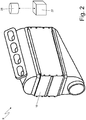
Figure 2 is a perspective view of the intercooler inFigure 1 integrated with an intake manifold; -
Figure 3 is an exploded perspective view of the intercooler inFigure 1 ; -
Figure 4 is a schematic longitudinal section view of a portion of the intercooler inFigure 1 ; -
Figure 5 is a perspective view of some exchanger plates of the intercooler inFigure 1 ; -
Figure 6 is a perspective view of a pocket and of a corresponding thermoelectric cell of an exchanger plate ofFigure 5 ; -
Figures 7 and8 are a top perspective view and a bottom perspective view, respectively, of a group of thermoelectric cells carried by an exchanger plate ofFigure 5 ; and -
Figure 9 is a diagram illustrating the performance of the energy efficiency of a thermoelectric cell as the equivalent electrical resistance changes at its terminals. - In
Figure 1 ,number 1 indicates as a whole an internal combustion heat engine, which is provided with adrive shaft 2 for transmitting motion to the drive wheels of a vehicle. - The internal
combustion heat engine 1 comprises fourcylinders 3, each of which is connected to anintake manifold 4 via at least one respective intake valve (not shown) and to anexhaust manifold 5 via at least one respective exhaust valve (not shown). Eachcylinder 3 houses, on the inside, a respective piston that slides with reciprocating motion and is mechanically connected to thedrive shaft 2; moreover, eachcylinder 3 is provided with its own injector which injects the fuel directly inside thecylinder 3. Theintake manifold 4 receives fresh air (i.e. air from the external environment) through anintake pipe 6, which is provided with anair filter 7 and is controlled by a throttle valve 8 (i.e. thethrottle valve 8 adjusts the flow rate of fresh air fed by theintake pipe 6 to the intake manifold 4). An intercooler 9 (i.e. a water-air heat exchanger), whose function is to cool the intake air so as to feed the air into thecylinders 3 at the optimal temperature for combustion, is arranged along theintake pipe 6. Theexhaust manifold 5 is connected to anexhaust pipe 10 that feeds the exhaust gases produced by combustion to an exhaust system, which emits the gases produced by combustion into the atmosphere and normally comprises at least onecatalyst 11 and at least one silencer (not shown) arranged downstream of thecatalyst 11. - The internal
combustion heat engine 1 is supercharged by aturbocharger supercharging system 12 comprising aturbocharger 13 provided with aturbine 14, which is arranged along theexhaust pipe 10 so as to rotate at high speed under the thrust of the exhaust gases expelled by thecylinders 3, and acompressor 15, which is rotated by theturbine 14 and arranged along the intake pipe 6 (upstream of the intercooler 9) so as to increase the pressure of the air fed by theintake pipe 6. According to a possible embodiment, not shown, thesupercharging system 12 may also comprise an electric machine, which is mechanically connected to the shaft of the turbocharger 13 (i.e. is mechanically connected to theturbine 14 and the compressor 15) and reversible (i.e. it can be operated as an electric motor to absorb electrical energy and produce a mechanical torque or as an electrical generator to absorb mechanical energy and produce electrical energy). - As shown in
Figures 2 and3 , theintercooler 9 is integrated with the intake manifold 4 (i.e., it forms a single body with the intake manifold 4) and comprises a parallelepipedal box-like body 16 having an air inlet opening 17 and an air outlet opening 18, opposite and facing each other (i.e. the inlet opening 17 and the outlet opening 18 are formed through opposite and parallel walls of the box-like body 16). Acooling chamber 19 is defined inside the box-like body 16, the former being delimited on two opposite sides by theopenings compressor 15 of theturbocharger 13 and directed toward theintake manifold 4. - As better shown in
Figure 4 , theintercooler 9 comprises a plurality ofexchanger plates 20, which are stacked on top of one another inside thecooling chamber 19, are arranged parallel to an air flowing direction D from the inlet opening 17 to the outlet opening 18, are spaced apart from one another so as to define corresponding air passage channels between one another, and are internally hollow (that is, internally they have at least one channel, one chamber). - As shown in
Figure 5 , theintercooler 9 comprises acirculation circuit 21, which allows a cooling fluid (typically water, optionally added with anti-freeze additives and/or anti-corrosion additives) to circulate inside the exchanger plates 20 (i.e. within the channels or chambers formed on the inside of the exchanger plates 20). A circulation path for the cooling fluid, extending between an inlet opening 22 and an outlet opening 23, is defined inside eachexchanger plate 20. Theopenings exchanger plates 20 are mutually aligned and superimposed so as to define respective channels that are connected to the remaining part of thecirculation circuit 21, which is arranged outside the box-like body 16 (i.e. the cooling chamber 19) and generally comprising a circulation pump and a radiator (i.e. an air-water heat exchanger). - As shown in
Figure 4 , theintercooler 9 comprises a plurality of solid-statethermoelectric cells 24, each of which has a substantially parallelepiped shape, is mounted on acorresponding exchanger plate 20, and has a cold side resting on theexchanger plate 20 and a hot side delimiting a corresponding air passage channel. Eachthermoelectric cell 24 is able to convert heat into electrical energy (through the Seebeck, Peltier and Thomson effect) when there is a difference in temperature between its own hot side and its own cold side; in order to ensure effective generation of electrical energy, it is necessary to ensure that the temperature of the cold side of eachthermoelectric cell 24 remains sufficiently lower than the temperature of the hot side, and it is therefore necessary to provide both constant heating to the hot side (through the intake air heated by thecompressor 15 of the turbocharger 13), and constant cooling to the cold side (through the circulation of the cooling fluid inside the exchanger plates 20). - The group of all the
thermoelectric cells 24 constitutes a thermoelectric generator (i.e. a device that is able to convert part of the heat of the air into electrical energy and is also called "TEG"). - As shown in
Figure 6 , eachexchanger plate 20 comprises a plurality of pockets 25 (in particular, eight pockets 25), each of which has a parallelepiped shape, reproduces in negative the shape of a correspondingthermoelectric cell 24, and houses therein thethermoelectric cell 24, surrounding saidthermoelectric cell 24 on five sides. In other words, eachexchanger plate 20 comprises a plurality of seats, parallelepipedal cavities (i.e. the pockets 25), which reproduce in negative the shape of thethermoelectric cells 24 and house saidthermoelectric cells 24. In particular, eachpocket 25 has a rectangular-shaped bottom wall which is arranged in direct contact with the cold side of the correspondingthermoelectric cell 24 and a side wall, which projects perpendicularly from the bottom wall, surrounds the bottom wall on the four sides, and is arranged in direct contact with a side wall of the correspondingthermoelectric cell 24; in this way, eachpocket 25 surrounds the correspondingthermoelectric cell 24 on five sides. The hot side of eachthermoelectric cell 24 is allowed to be hit by the flow of hot air (to be cooled down) coming from thecompressor 15 of theturbocharger 13, whereas the cold side of eachthermoelectric cell 24 is located inside acorresponding pocket 25 and rests on a wall of theexchanger plate 20. - According to a preferred embodiment, each
pocket 25 has a depth equal to a thickness of the correspondingthermoelectric cell 24 so that the side wall of thethermoelectric cell 24 is completely covered by the side wall of thepocket 25 and then in such a way that the hot side of thethermoelectric cell 24 is flush with an external surface of thecorresponding exchanger plate 20; i.e. eachthermoelectric cell 24 does not protrude from the external surface of thecorresponding exchanger plate 20, but is perfectly flush with the external surface of the corresponding exchanger plate 20 (i.e. the hot side of eachthermoelectric cell 24 is aligned and coplanar with the external surface of the corresponding exchanger plate 20). - According to a possible and non-limiting embodiment, a sheet of graphite (or other similar material), which is a thermally conductive and easily deformable material (i.e. it is a "soft" material) is interposed between the cold side of each
thermoelectric cell 24 and the corresponding wall of the exchanger plate 20 (i.e. the corresponding wall of thepocket 25 formed in the exchanger plate 20); the function of each sheet of graphite is to improve the contact (i.e. to increase the contact surface) between one side of thethermoelectric cell 24 and the corresponding wall of theexchanger plate 20 in order to enhance the heat exchange and evenly fill in any surface irregularities. - As shown in
Figures 4 ,7 and8 , eachexchanger plate 20 comprises two rows of thermoelectric cells 24 (in particular, two rows of fourthermoelectric cells 24 each) and a plurality offins 26, which are interposed between the rows ofthermoelectric cells 24 and are arranged parallel to the air flowing direction D from the inlet opening 17 to the outlet opening 18. The function of thefins 26 arranged centrally (i.e. between the two rows of thermoelectric cells 24) is to increase the heat exchange surface of eachexchanger plate 20 that is licked by the air passing through thecooling chamber 19 so as to make the cooling of the air more effective. A further function of thefins 26 arranged centrally (i.e. between the two rows of thermoelectric cells 24) is to space thethermoelectric cells 24 of a row away from thethermoelectric cells 24 of the other row so that, between the two rows, thethermoelectric cells 24 do not affect each other and in a negative way. In particular, in order to avoid reciprocal and negative influences between thethermoelectric cells 24 of the two rows, the extent of thefins 26 along the air flowing direction D must be at least 70-80% of the extent of thethermoelectric cells 24 in the same air flowing direction D. - According to a preferred embodiment better illustrated in
Figure 8 , in eachexchanger plate 20 the fourthermoelectric cells 24 of a same row are electrically interconnected in series. The groups of fourthermoelectric cells 24 electrically interconnected in series can in turn be connected together in series and/or in parallel. - The
intercooler 9 comprises an electronic DC-DC converter 27 (shown schematically inFigure 2 ) which is arranged outside the cooling chamber 19 (i.e. outside the box-like body 16). The electronic DC-DC converter 27, at the input, is connected to an electrical circuit connecting all thethermoelectric cells 24 and, at the output, provides an electric voltage that is always constant and equal to a predetermined nominal value (for example 12 Volts for charging a battery of a vehicle equipped with the internal combustion heat engine 1). The voltage entering the electronic DC-DC converter 27 (i.e. the voltage supplied by the thermoelectric generator constituted by the thermoelectric cells 24) changes continuously as the instantaneous air temperature from thecompressor 15 of theturbocharger 13 changes, and hence the electronic DC-DC converter 27 must continuously adjust its transformation ratio in order to maintain a constant output voltage (for example equal to 12 Volts). - By way of example, the electronic DC-
DC converter 27 may be of the "buck-boost" type; the "buck-boost" converter is a type of DC-DC converter that has a continuous voltage output higher or lower than the input voltage. - Finally, the
intercooler 9 comprises anelectronic control unit 28, which is connected to the electronic DC-DC converter 27 and controls the electronic DC-DC converter 27 by adjusting the equivalent electrical resistance perceived by the electrical circuit connecting all thethermoelectric cells 24 in order to pursue an optimal equivalent electrical resistance (i.e. an equivalent electrical resistance which allows the energy efficiency of thethermoelectric cells 24 to be maximized, i.e. the overall electrical power generated by thethermoelectric cells 24 to be maximized in all conditions). In the embodiment shown inFigure 2 , theelectronic control unit 28 controls the electronic DC-DC converter 27 by adjusting the equivalent electrical resistance perceived by the electrical circuit connecting all thethermoelectric cells 24 so as to pursue an optimal equivalent electrical resistance. According to alternative embodiments, theelectronic control unit 28 controls the electronic DC-DC converter 27 by adjusting the equivalent electrical resistance perceived by individual groups of thermoelectric cells 24 (for example by all eightthermoelectric cells 24 of asame exchanger plate 20 or by the fourthermoelectric cells 24 of a same row of a same exchanger plate 20) or, in the limit case, by the individualthermoelectric cells 24; in fact, the variousthermoelectric cells 24 operate under different conditions (for example, thethermoelectric cells 24 arranged upstream with respect to the air flowing direction D are subjected to a greater temperature shift than thethermoelectric cells 24 arranged downstream with respect to the air flowing direction D, or thethermoelectric cells 24 arranged at the centre of thecooling chamber 19 are subjected to a greater temperature shift than thethermoelectric cells 24 arranged at the edges of the cooling chamber 19), and therefore a differentiated optimization is more effective (but also more complicated) than an overall optimization. - For example, the
electronic control unit 28 could control the electronic DC-DC converter 27 by using an MPPT ("Maximum Power Point Tracker") algorithm: thethermoelectric cells 24 have a characteristic voltage/current (or equivalent electrical resistance) curve exhibiting an optimum working point, called "Maximum Power Point", where the maximum possible electrical power can be extracted. This point of the characteristic voltage/current changes continuously according to the temperature shift to which thethermoelectric cells 24 are subjected. Thus, the electronic DC-DC converter 27 must continuously change the equivalent electrical resistance perceived by the electrical circuit connecting all thethermoelectric cells 24 to try to pursue the optimum working point ("Maximum Power Point"). - In other words, the electronic DC-DC converter 27 (controlled by the electronic control unit 28) has the double task of maintaining a constant output voltage (for example 12 Volts) and at the same time changing the input resistance perceived by the thermoelectric generator (i.e. by the electrical circuit connecting all the thermoelectric cells 24) in order to pursue the maximum efficiency working point (i.e. with the maximum generated power). This is because, at the same temperature shift, a
thermoelectric cell 24 generates a different electrical power based on the variation of the electrical resistance perceived at its terminals; as shown in the graph ofFigure 9 (in which the abscissa represents the electrical resistance R perceived at the terminals of athermoelectric cell 24 and the ordinate represents the energy efficiency η of the thermoelectric cell 24), at the same temperature shift, the energy efficiency of athermoelectric cell 24 is maximum when the electrical resistance perceived at its terminals is approximately 0.75-2 Ohms. - Preferably, each
exchanger plate 20, together with the correspondingthermoelectric cells 24, is part of a generator module, which is independent and separate from the other generator modules. Preferably, in each generator module, all thethermoelectric cells 24 are interconnected in series and each generator module is provided with its own control electronics, which is able to short-circuit (bypass) any non-functioning (i.e. broken-down)thermoelectric cell 24, as well as to make the terminals of eachthermoelectric cell 24 perceive a variable and optimal equivalent electrical resistance, allowing the generation of electrical energy to be maximized by using an MPPT ("Maximum Power Point Tracker") algorithm. In other words, the control electronics of each generator module on the input side (i.e. on the side connected to the two terminals of each thermoelectric cell 24) preferably creates an equivalent electrical resistance such that the voltage between the two terminals of thethermoelectric cell 24 and the electric current flowing through the two terminals of thethermoelectric cell 24 have such values as to optimize the operation of the thermoelectric generator (i.e. to maximize the generation of electrical energy). - By way of example, the
intercooler 9 could comprise fifteenexchanger plates 20, each housing eight thermoelectric cells 24 (divided into two rows of fourthermoelectric cells 24 each). The nominal electrical power of eachthermoelectric cell 24 is approximately 6 Watts and hence altogether the thermoelectric generator has a nominal power of 700 Watts (as there are a total of one hundred and twenty thermoelectric cells 24). A good thermoelectric material has a Seebeck coefficient between 100 µV/K and 300 µV/K, therefore, to obtain a few volts at the output of the thermoelectric generator (i.e. at the input of the electronic DC-DC converter 27) manythermoelectric cells 24 must be connected in series. - According to a possible embodiment, the thermoelectric generator could be able to generate an electrical power high enough to supply all the low voltage electrical loads of the vehicle, and therefore could obviate any need for an alternator generating electrical energy by using part of the mechanical power of the drive shaft. In other words, the thermoelectric generator could completely replace the traditional alternator that generates electrical energy by using part of the mechanical power of the drive shaft.
- According to a preferred embodiment, the distance between two
adjacent exchanger plates 20 is such that the flow of air is laminar; in this way, the energy efficiency of thethermoelectric cells 24 can be improved. Similarly, the distance between the support turrets of theexchanger plates 20 is such that the flow of air is laminar; in this way, the energy efficiency of thethermoelectric cells 24 can be improved. - The embodiments described herein may be combined with each other without departing from the scope of protection of the present invention.
- The
intercooler 9 described above has many advantages. - Firstly, the
intercooler 9 described above allows high energy efficiency in the generation of electrical energy, as it allows excellent heat transmission from the air coming from thecompressor 15 of theturbocharger 13. - In addition, the
intercooler 9 described above uses only solid-statethermoelectric cells 24 and therefore is entirely devoid of parts that move and hence subject to wear; consequently, theintercooler 9 described above requires no maintenance and has a very long operating life. In addition, theintercooler 9 described above does not generate acoustic noise or high frequency electrical noise. - The
intercooler 9 described above results in an extremely low weight increase with respect to asimilar intercooler 9 devoid ofthermoelectric cells 24, because in fact the weight increase is due solely to the insertion of thethermoelectric cells 24, and all the other parts of theintercooler 9 described above are also present (possibly with a different conformation) in asimilar intercooler 9 devoid ofthermoelectric cells 24. - In the
intercooler 9 described above, thethermoelectric cells 24 are subjected to relatively limited thermal stresses and therefore do not need to be designed to withstand severe thermal stresses, with considerable savings in costs (in essence, it is possible to use standard "commercial"thermoelectric cells 24 instead of "special"thermoelectric cells 24 having much higher purchase costs). This result is obtained thanks to the fact that thethermoelectric cells 24 are "buried" ("embedded") in theexchanger plates 20, i.e. are inserted in correspondingpockets 25, which, by surrounding thethermoelectric cells 24 on five sides, prevent saidthermoelectric cells 24 from heating up too much. The air coming from thecompressor 15 of the turbocharger can have a maximum temperature close to 400°C, whereas a standard "commercial"thermoelectric cell 24 can withstand a maximum temperature of about 200°C; it is therefore necessary to ensure an optimal thermal contact between thethermoelectric cells 24 and the cooling fluid (having a working temperature of 80-90°C) which flows inside theexchanger plates 25 to prevent thethermoelectric cells 24 from internally exceeding the maximum temperature of about 200°C even when they are hit by air having a temperature close to 400°C. - Lastly, the
intercooler 9 described above has an insignificant size increase compared to asimilar intercooler 9 devoid ofthermoelectric cells 24, since the total volume of thethermoelectric cells 24 is negligible relative to the overall volume of the coolingchamber 19. -
- 1
- heat engine
- 2
- drive shaft
- 3
- cylinders
- 4
- intake manifold
- 5
- exhaust manifold
- 6
- intake pipe
- 7
- air filter
- 8
- throttle valve
- 9
- intercooler
- 10
- exhaust pipe
- 11
- catalyst
- 12
- turbocharger supercharging system
- 13
- turbocharger
- 14
- turbine
- 15
- compressor
- 16
- box-like body
- 17
- inlet opening
- 18
- outlet opening
- 19
- cooling chamber
- 20
- exchanger plates
- 21
- circulation circuit
- 22
- inlet opening
- 23
- outlet opening
- 24
- thermoelectric cells
- 25
- 26
- fins
- 27
- electronic DC-DC converter
- 28
- electronic control unit
- D
- air flowing direction
Claims (9)
- An intercooler (9) for a turbocharged internal combustion heat engine (1); the intercooler (9) comprises:a cooling chamber (19), which is provided with an air inlet opening (17) and an air outlet opening (18) opposite one another;a plurality of exchanger plates (20), which are stacked on top of one another inside the cooling chamber (19), are arranged parallel to an air flowing direction (D) from the inlet opening (17) to the outlet opening (18), are spaced apart from one another so as to define corresponding air passage channels between one another, and are internally hollow;a circulation circuit (21), which allows a cooling fluid to circulate inside the exchanger plates (20); anda plurality of thermoelectric cells (24), each of which has a parallelepiped shape, is mounted on a corresponding exchanger plate (20), and has a cold side resting on the exchanger plate (20) and a hot side delimiting a corresponding air passage channel;the intercooler (9) is characterised in that each exchanger plate (20) comprises at least one parallelepipedal pocket (25), which reproduces in negative the shape of a corresponding thermoelectric cell (24) and houses therein the thermoelectric cell (24) surrounding the thermoelectric cell (24) on five sides.
- The intercooler (9) according to claim 1, wherein each pocket (25) has a rectangular-shaped bottom wall which is arranged in direct contact with the cold side of the corresponding thermoelectric cell (24) and a side wall, which projects perpendicularly from the bottom wall, surrounds the bottom wall on the four sides, and is arranged in direct contact with a side wall of the corresponding thermoelectric cell (24).
- The intercooler (9) according to claim 2, wherein each pocket (25) has a depth equal to a thickness of the corresponding thermoelectric cell (24) so that the side wall of the thermoelectric cell (24) is completely covered by the side wall of the pocket (25) and then in such a way that the hot side of the thermoelectric cell (24) is flush with an external surface of the corresponding exchanger plate (20).
- The intercooler (9) according to claim 2 or 3, wherein each thermoelectric cell (24) does not protrude from an external surface of the corresponding exchanger plate (20) and is perfectly flush with the external surface of the corresponding exchanger plate (20).
- The intercooler (9) according to claim 2, 3 or 4, wherein the hot side of each thermoelectric cell (24) is aligned and coplanar with an external surface of the corresponding exchanger plate (20).
- The intercooler (9) according to one of the claims from 1 to 5, wherein each exchanger plate (20) comprises two rows of thermoelectric cells (24) and a plurality of fins (26), which are interposed between the rows of thermoelectric cells (24) and are arranged parallel to the air flowing direction (D) from the inlet opening (17) to the outlet opening (18).
- The intercooler (9) according to claim 6, wherein the extent of the fins (26) along the air flowing direction (D) is at least 70% of the extent of the thermoelectric cells (24) in the same air flowing direction (D).
- The intercooler (9) according to one of the claims from 1 to 7 and comprising an electronic DC-DC converter (27), which, at the input, is connected to an electrical circuit connecting all the thermoelectric cells (24) and, at the output, provides an electric voltage that is always constant and equal to a predetermined nominal value.
- The intercooler (9) according to one of the claims from 1 to 8 and comprising an electronic control unit (28), which changes the equivalent electrical resistance perceived by each thermoelectric cell (24) or by a group of thermoelectric cells (24) electrically connected to one another, so as to pursue an optimal equivalent electrical resistance.
Applications Claiming Priority (1)
| Application Number | Priority Date | Filing Date | Title |
|---|---|---|---|
| IT201700147426 | 2017-12-20 |
Publications (2)
| Publication Number | Publication Date |
|---|---|
| EP3503229A1 true EP3503229A1 (en) | 2019-06-26 |
| EP3503229B1 EP3503229B1 (en) | 2020-08-05 |
Family
ID=61187773
Family Applications (1)
| Application Number | Title | Priority Date | Filing Date |
|---|---|---|---|
| EP18214934.4A Active EP3503229B1 (en) | 2017-12-20 | 2018-12-20 | Intercooler provided with a thermoelectric generator for a turbocharged internal combustion engine |
Country Status (5)
| Country | Link |
|---|---|
| US (1) | US10865702B2 (en) |
| EP (1) | EP3503229B1 (en) |
| JP (1) | JP2019143621A (en) |
| CN (1) | CN109944680A (en) |
| BR (1) | BR102018076652A2 (en) |
Cited By (1)
| Publication number | Priority date | Publication date | Assignee | Title |
|---|---|---|---|---|
| DE102019218509A1 (en) * | 2019-11-28 | 2021-06-02 | Volkswagen Aktiengesellschaft | Internal combustion engine with a charge air cooler and with a control device for controlling or regulating an electrically operated element of a vehicle |
Families Citing this family (1)
| Publication number | Priority date | Publication date | Assignee | Title |
|---|---|---|---|---|
| US20250072287A1 (en) * | 2023-08-22 | 2025-02-27 | Atieva, Inc. | Obtaining high coefficient of performance in heating or cooling by using thermoelectric module(s) |
Citations (9)
| Publication number | Priority date | Publication date | Assignee | Title |
|---|---|---|---|---|
| US5547019A (en) * | 1994-10-28 | 1996-08-20 | Iacullo; Robert S. | Thermoelectric intercooler cooling turbocharged air |
| DE102008051843A1 (en) | 2008-10-17 | 2010-04-29 | Mahle International Gmbh | Internal-combustion engine for motor vehicle, has thermoelectric transducer comprising set of thermoelectric elements that are coupled with charged fresh air in heat-transferring manner |
| US20110083831A1 (en) | 2008-05-15 | 2011-04-14 | Bayerische Motoren Werke Aktiengesellschaft | Cooling System for a Thermoelectric Power Generator |
| WO2011107282A1 (en) | 2010-03-03 | 2011-09-09 | Faurecia Emissions Control Technologies, Germany Gmbh | Device for the utilization of exhaust-gas heat |
| DE102012217215A1 (en) | 2012-09-25 | 2014-06-12 | Bayerische Motoren Werke Aktiengesellschaft | Charge air cooler for internal combustion engine e.g. diesel engines for use in motor vehicles, has first electrical bridges whose averse surface is flowed around legs of thermoelectric device directly from charge air to be tempered |
| EP2765285A1 (en) | 2013-02-11 | 2014-08-13 | Delphi Technologies, Inc. | Heat exchanger equipped with thermal electric device for engine exhaust carbon dioxide collection system |
| US20140305481A1 (en) | 2013-04-12 | 2014-10-16 | Delphi Technologies, Inc. | Thermoelectric generator to engine exhaust manifold assembly |
| US20150128590A1 (en) | 2013-11-12 | 2015-05-14 | Hyundai America Technical Center, Inc. | Thermoelectric generator insert for engine waste heat recovery |
| US20160155922A1 (en) | 2014-11-29 | 2016-06-02 | Hyundai Motor Company | Thermoelectric generator sleeve for a catalytic converter |
Family Cites Families (24)
| Publication number | Priority date | Publication date | Assignee | Title |
|---|---|---|---|---|
| US3077080A (en) * | 1961-12-12 | 1963-02-12 | Gen Electric | Thermoelectric air conditioning apparatus |
| US3138934A (en) * | 1962-11-19 | 1964-06-30 | Kysor Industrial Corp | Thermoelectric heating and cooling system for vehicles |
| DE19954690A1 (en) * | 1999-11-13 | 2001-05-17 | Porsche Ag | Air intake for an IC motor has a cooling unit for the air drawn in fitted with Peltier elements as a compact system easily fitted to the air intake installation |
| US7171955B2 (en) * | 2003-10-20 | 2007-02-06 | Perkins Michael T | Flowing fluid conditioner |
| US20080308140A1 (en) * | 2004-08-17 | 2008-12-18 | The Furukawa Electric Co., Ltd. | Thermo-Electric Cooling Device |
| US20060118157A1 (en) * | 2004-12-03 | 2006-06-08 | Caterpillar Inc | Thermoelectric generator and control system |
| EP1965446B1 (en) * | 2007-02-28 | 2011-11-16 | Corning Incorporated | Glass-ceramic thermoelectric module |
| JP2009081970A (en) * | 2007-09-27 | 2009-04-16 | Ihi Marine United Inc | Thermoelectric power generator and power generation system using the thermoelectric power generator |
| DE102009046318A1 (en) * | 2009-11-03 | 2011-05-12 | Robert Bosch Gmbh | Thermoelectric generator and method for its production |
| DE102010054432B4 (en) * | 2010-12-14 | 2023-02-09 | Friedrich Boysen Gmbh & Co. Kg | Device for converting thermal energy into electrical energy, as well as system and exhaust system with such a device |
| DE102011005246A1 (en) * | 2011-03-08 | 2012-09-13 | Behr Gmbh & Co. Kg | Method for producing a thermoelectric module |
| JP2012209305A (en) * | 2011-03-29 | 2012-10-25 | Toyota Industries Corp | Thermoelectric conversion unit and manufacturing method of the same |
| WO2012170570A1 (en) * | 2011-06-07 | 2012-12-13 | B/E Aerospace, Inc. | Thermoelectric cooling system for a food and beverage compartment |
| JP2013008734A (en) * | 2011-06-22 | 2013-01-10 | Toyota Industries Corp | Thermoelectric conversion unit |
| US9343646B2 (en) * | 2011-10-06 | 2016-05-17 | Aktiebolaget Skf | Thermo-electric power harvesting bearing configuration |
| DE102012206127A1 (en) * | 2012-04-13 | 2013-10-17 | Behr Gmbh & Co. Kg | Thermoelectric device for use in motor car, has fluid flow channels whose one side ends are fluid communicated with two batteries respectively while other side ends are fluid communicated with other two batteries respectively |
| DE102012214704A1 (en) * | 2012-08-17 | 2014-03-27 | Behr Gmbh & Co. Kg | Thermoelectric module |
| DE102012222635A1 (en) * | 2012-12-10 | 2014-06-12 | Behr Gmbh & Co. Kg | Heat exchanger, in particular for a motor vehicle |
| DE102014208433A1 (en) * | 2014-05-06 | 2015-11-26 | MAHLE Behr GmbH & Co. KG | Thermoelectric device, in particular for a motor vehicle |
| JP6685648B2 (en) * | 2015-02-25 | 2020-04-22 | 千代田化工建設株式会社 | Power generation system |
| CN107735900A (en) * | 2015-06-10 | 2018-02-23 | 金瑟姆股份有限公司 | Vehicular battery thermoelectric device with integrated cold drawing assembly |
| JP6851945B2 (en) * | 2017-09-19 | 2021-03-31 | 株式会社東芝 | Thermoelectric generation system |
| EP3505859A1 (en) * | 2017-12-26 | 2019-07-03 | Borgwarner Emissions Systems Spain, S.L.U. | Recuperator device for recovering energy from exhaust gas heat |
| WO2020051576A1 (en) * | 2018-09-07 | 2020-03-12 | Balma Jacob A | Fine-grain dynamic solid-state cooling system |
-
2018
- 2018-12-19 JP JP2018237350A patent/JP2019143621A/en active Pending
- 2018-12-19 US US16/226,083 patent/US10865702B2/en not_active Expired - Fee Related
- 2018-12-20 CN CN201811564186.8A patent/CN109944680A/en active Pending
- 2018-12-20 BR BR102018076652A patent/BR102018076652A2/en not_active Application Discontinuation
- 2018-12-20 EP EP18214934.4A patent/EP3503229B1/en active Active
Patent Citations (9)
| Publication number | Priority date | Publication date | Assignee | Title |
|---|---|---|---|---|
| US5547019A (en) * | 1994-10-28 | 1996-08-20 | Iacullo; Robert S. | Thermoelectric intercooler cooling turbocharged air |
| US20110083831A1 (en) | 2008-05-15 | 2011-04-14 | Bayerische Motoren Werke Aktiengesellschaft | Cooling System for a Thermoelectric Power Generator |
| DE102008051843A1 (en) | 2008-10-17 | 2010-04-29 | Mahle International Gmbh | Internal-combustion engine for motor vehicle, has thermoelectric transducer comprising set of thermoelectric elements that are coupled with charged fresh air in heat-transferring manner |
| WO2011107282A1 (en) | 2010-03-03 | 2011-09-09 | Faurecia Emissions Control Technologies, Germany Gmbh | Device for the utilization of exhaust-gas heat |
| DE102012217215A1 (en) | 2012-09-25 | 2014-06-12 | Bayerische Motoren Werke Aktiengesellschaft | Charge air cooler for internal combustion engine e.g. diesel engines for use in motor vehicles, has first electrical bridges whose averse surface is flowed around legs of thermoelectric device directly from charge air to be tempered |
| EP2765285A1 (en) | 2013-02-11 | 2014-08-13 | Delphi Technologies, Inc. | Heat exchanger equipped with thermal electric device for engine exhaust carbon dioxide collection system |
| US20140305481A1 (en) | 2013-04-12 | 2014-10-16 | Delphi Technologies, Inc. | Thermoelectric generator to engine exhaust manifold assembly |
| US20150128590A1 (en) | 2013-11-12 | 2015-05-14 | Hyundai America Technical Center, Inc. | Thermoelectric generator insert for engine waste heat recovery |
| US20160155922A1 (en) | 2014-11-29 | 2016-06-02 | Hyundai Motor Company | Thermoelectric generator sleeve for a catalytic converter |
Cited By (1)
| Publication number | Priority date | Publication date | Assignee | Title |
|---|---|---|---|---|
| DE102019218509A1 (en) * | 2019-11-28 | 2021-06-02 | Volkswagen Aktiengesellschaft | Internal combustion engine with a charge air cooler and with a control device for controlling or regulating an electrically operated element of a vehicle |
Also Published As
| Publication number | Publication date |
|---|---|
| US20190186347A1 (en) | 2019-06-20 |
| BR102018076652A2 (en) | 2019-08-13 |
| CN109944680A (en) | 2019-06-28 |
| JP2019143621A (en) | 2019-08-29 |
| EP3503229B1 (en) | 2020-08-05 |
| US10865702B2 (en) | 2020-12-15 |
Similar Documents
| Publication | Publication Date | Title |
|---|---|---|
| CN101000972B (en) | Thermal control device for battery of mixed power vehicle | |
| US4753682A (en) | Apparatus of thermoelectric effect for current generation in internal combustion engine vehicles and the like, with recovery of the externally dissipated heat | |
| US20060130888A1 (en) | Thermoelectric generator | |
| US9461346B2 (en) | Method for air cooling of an electric vehicle traction battery with flow shifting | |
| US20080098750A1 (en) | Thermoelectric cooling/heating device | |
| GB2453218A (en) | Internal combustion engine cooling system | |
| WO2010014292A2 (en) | Thermoelectric power generator for variable thermal power source | |
| US20150214458A1 (en) | Thermoelectric generator system for intercooler coupled to turbocharger | |
| US20090139556A1 (en) | Thermoelectric power generator with intermediate loop | |
| GB2541006A (en) | Hybrid vehicle cooling system | |
| EP3503229B1 (en) | Intercooler provided with a thermoelectric generator for a turbocharged internal combustion engine | |
| EP0167807B1 (en) | A supercharger system for use with heat engines | |
| JP6417949B2 (en) | Thermoelectric generator | |
| US8793992B2 (en) | Thermoelectric device for use with Stirling engine | |
| WO2016188666A1 (en) | System for thermal management of an electric vehicle | |
| KR20130068326A (en) | Automotive thermoelectric generator | |
| CN110546365B (en) | Method and system for a multi-stage exhaust gas cooler | |
| CN214304040U (en) | Turbocharger and turbocharging system | |
| JP2012057579A (en) | Egr cooler of internal combustion engine | |
| CN221437672U (en) | Thermal management system of hybrid electric vehicle | |
| CN105909433B (en) | Air intlet for internal combustion engine | |
| WO2014114950A2 (en) | Thermoelectric generators | |
| JP4315070B2 (en) | Waste heat recovery device for internal combustion engine | |
| US20160326948A1 (en) | Intake air cooling device of internal combustion engine | |
| JP2017115589A (en) | Internal combustion engine |
Legal Events
| Date | Code | Title | Description |
|---|---|---|---|
| PUAI | Public reference made under article 153(3) epc to a published international application that has entered the european phase |
Free format text: ORIGINAL CODE: 0009012 |
|
| STAA | Information on the status of an ep patent application or granted ep patent |
Free format text: STATUS: THE APPLICATION HAS BEEN PUBLISHED |
|
| AK | Designated contracting states |
Kind code of ref document: A1 Designated state(s): AL AT BE BG CH CY CZ DE DK EE ES FI FR GB GR HR HU IE IS IT LI LT LU LV MC MK MT NL NO PL PT RO RS SE SI SK SM TR |
|
| AX | Request for extension of the european patent |
Extension state: BA ME |
|
| STAA | Information on the status of an ep patent application or granted ep patent |
Free format text: STATUS: REQUEST FOR EXAMINATION WAS MADE |
|
| 17P | Request for examination filed |
Effective date: 20191217 |
|
| GRAP | Despatch of communication of intention to grant a patent |
Free format text: ORIGINAL CODE: EPIDOSNIGR1 |
|
| STAA | Information on the status of an ep patent application or granted ep patent |
Free format text: STATUS: GRANT OF PATENT IS INTENDED |
|
| INTG | Intention to grant announced |
Effective date: 20200227 |
|
| GRAS | Grant fee paid |
Free format text: ORIGINAL CODE: EPIDOSNIGR3 |
|
| GRAA | (expected) grant |
Free format text: ORIGINAL CODE: 0009210 |
|
| STAA | Information on the status of an ep patent application or granted ep patent |
Free format text: STATUS: THE PATENT HAS BEEN GRANTED |
|
| AK | Designated contracting states |
Kind code of ref document: B1 Designated state(s): AL AT BE BG CH CY CZ DE DK EE ES FI FR GB GR HR HU IE IS IT LI LT LU LV MC MK MT NL NO PL PT RO RS SE SI SK SM TR |
|
| REG | Reference to a national code |
Ref country code: GB Ref legal event code: FG4D |
|
| REG | Reference to a national code |
Ref country code: CH Ref legal event code: EP |
|
| REG | Reference to a national code |
Ref country code: AT Ref legal event code: REF Ref document number: 1299965 Country of ref document: AT Kind code of ref document: T Effective date: 20200815 |
|
| REG | Reference to a national code |
Ref country code: DE Ref legal event code: R096 Ref document number: 602018006686 Country of ref document: DE |
|
| REG | Reference to a national code |
Ref country code: IE Ref legal event code: FG4D |
|
| REG | Reference to a national code |
Ref country code: LT Ref legal event code: MG4D |
|
| REG | Reference to a national code |
Ref country code: NL Ref legal event code: MP Effective date: 20200805 |
|
| REG | Reference to a national code |
Ref country code: AT Ref legal event code: MK05 Ref document number: 1299965 Country of ref document: AT Kind code of ref document: T Effective date: 20200805 |
|
| PG25 | Lapsed in a contracting state [announced via postgrant information from national office to epo] |
Ref country code: AT Free format text: LAPSE BECAUSE OF FAILURE TO SUBMIT A TRANSLATION OF THE DESCRIPTION OR TO PAY THE FEE WITHIN THE PRESCRIBED TIME-LIMIT Effective date: 20200805 Ref country code: NO Free format text: LAPSE BECAUSE OF FAILURE TO SUBMIT A TRANSLATION OF THE DESCRIPTION OR TO PAY THE FEE WITHIN THE PRESCRIBED TIME-LIMIT Effective date: 20201105 Ref country code: FI Free format text: LAPSE BECAUSE OF FAILURE TO SUBMIT A TRANSLATION OF THE DESCRIPTION OR TO PAY THE FEE WITHIN THE PRESCRIBED TIME-LIMIT Effective date: 20200805 Ref country code: LT Free format text: LAPSE BECAUSE OF FAILURE TO SUBMIT A TRANSLATION OF THE DESCRIPTION OR TO PAY THE FEE WITHIN THE PRESCRIBED TIME-LIMIT Effective date: 20200805 Ref country code: HR Free format text: LAPSE BECAUSE OF FAILURE TO SUBMIT A TRANSLATION OF THE DESCRIPTION OR TO PAY THE FEE WITHIN THE PRESCRIBED TIME-LIMIT Effective date: 20200805 Ref country code: SE Free format text: LAPSE BECAUSE OF FAILURE TO SUBMIT A TRANSLATION OF THE DESCRIPTION OR TO PAY THE FEE WITHIN THE PRESCRIBED TIME-LIMIT Effective date: 20200805 Ref country code: BG Free format text: LAPSE BECAUSE OF FAILURE TO SUBMIT A TRANSLATION OF THE DESCRIPTION OR TO PAY THE FEE WITHIN THE PRESCRIBED TIME-LIMIT Effective date: 20201105 Ref country code: GR Free format text: LAPSE BECAUSE OF FAILURE TO SUBMIT A TRANSLATION OF THE DESCRIPTION OR TO PAY THE FEE WITHIN THE PRESCRIBED TIME-LIMIT Effective date: 20201106 Ref country code: ES Free format text: LAPSE BECAUSE OF FAILURE TO SUBMIT A TRANSLATION OF THE DESCRIPTION OR TO PAY THE FEE WITHIN THE PRESCRIBED TIME-LIMIT Effective date: 20200805 Ref country code: PT Free format text: LAPSE BECAUSE OF FAILURE TO SUBMIT A TRANSLATION OF THE DESCRIPTION OR TO PAY THE FEE WITHIN THE PRESCRIBED TIME-LIMIT Effective date: 20201207 |
|
| PGFP | Annual fee paid to national office [announced via postgrant information from national office to epo] |
Ref country code: FR Payment date: 20201120 Year of fee payment: 3 Ref country code: DE Payment date: 20201119 Year of fee payment: 3 |
|
| PG25 | Lapsed in a contracting state [announced via postgrant information from national office to epo] |
Ref country code: IS Free format text: LAPSE BECAUSE OF FAILURE TO SUBMIT A TRANSLATION OF THE DESCRIPTION OR TO PAY THE FEE WITHIN THE PRESCRIBED TIME-LIMIT Effective date: 20201205 Ref country code: LV Free format text: LAPSE BECAUSE OF FAILURE TO SUBMIT A TRANSLATION OF THE DESCRIPTION OR TO PAY THE FEE WITHIN THE PRESCRIBED TIME-LIMIT Effective date: 20200805 Ref country code: RS Free format text: LAPSE BECAUSE OF FAILURE TO SUBMIT A TRANSLATION OF THE DESCRIPTION OR TO PAY THE FEE WITHIN THE PRESCRIBED TIME-LIMIT Effective date: 20200805 Ref country code: PL Free format text: LAPSE BECAUSE OF FAILURE TO SUBMIT A TRANSLATION OF THE DESCRIPTION OR TO PAY THE FEE WITHIN THE PRESCRIBED TIME-LIMIT Effective date: 20200805 Ref country code: NL Free format text: LAPSE BECAUSE OF FAILURE TO SUBMIT A TRANSLATION OF THE DESCRIPTION OR TO PAY THE FEE WITHIN THE PRESCRIBED TIME-LIMIT Effective date: 20200805 |
|
| PG25 | Lapsed in a contracting state [announced via postgrant information from national office to epo] |
Ref country code: EE Free format text: LAPSE BECAUSE OF FAILURE TO SUBMIT A TRANSLATION OF THE DESCRIPTION OR TO PAY THE FEE WITHIN THE PRESCRIBED TIME-LIMIT Effective date: 20200805 Ref country code: CZ Free format text: LAPSE BECAUSE OF FAILURE TO SUBMIT A TRANSLATION OF THE DESCRIPTION OR TO PAY THE FEE WITHIN THE PRESCRIBED TIME-LIMIT Effective date: 20200805 Ref country code: DK Free format text: LAPSE BECAUSE OF FAILURE TO SUBMIT A TRANSLATION OF THE DESCRIPTION OR TO PAY THE FEE WITHIN THE PRESCRIBED TIME-LIMIT Effective date: 20200805 Ref country code: RO Free format text: LAPSE BECAUSE OF FAILURE TO SUBMIT A TRANSLATION OF THE DESCRIPTION OR TO PAY THE FEE WITHIN THE PRESCRIBED TIME-LIMIT Effective date: 20200805 Ref country code: SM Free format text: LAPSE BECAUSE OF FAILURE TO SUBMIT A TRANSLATION OF THE DESCRIPTION OR TO PAY THE FEE WITHIN THE PRESCRIBED TIME-LIMIT Effective date: 20200805 |
|
| REG | Reference to a national code |
Ref country code: DE Ref legal event code: R097 Ref document number: 602018006686 Country of ref document: DE |
|
| PG25 | Lapsed in a contracting state [announced via postgrant information from national office to epo] |
Ref country code: AL Free format text: LAPSE BECAUSE OF FAILURE TO SUBMIT A TRANSLATION OF THE DESCRIPTION OR TO PAY THE FEE WITHIN THE PRESCRIBED TIME-LIMIT Effective date: 20200805 |
|
| PLBE | No opposition filed within time limit |
Free format text: ORIGINAL CODE: 0009261 |
|
| STAA | Information on the status of an ep patent application or granted ep patent |
Free format text: STATUS: NO OPPOSITION FILED WITHIN TIME LIMIT |
|
| PG25 | Lapsed in a contracting state [announced via postgrant information from national office to epo] |
Ref country code: SK Free format text: LAPSE BECAUSE OF FAILURE TO SUBMIT A TRANSLATION OF THE DESCRIPTION OR TO PAY THE FEE WITHIN THE PRESCRIBED TIME-LIMIT Effective date: 20200805 |
|
| 26N | No opposition filed |
Effective date: 20210507 |
|
| PG25 | Lapsed in a contracting state [announced via postgrant information from national office to epo] |
Ref country code: MC Free format text: LAPSE BECAUSE OF FAILURE TO SUBMIT A TRANSLATION OF THE DESCRIPTION OR TO PAY THE FEE WITHIN THE PRESCRIBED TIME-LIMIT Effective date: 20200805 Ref country code: SI Free format text: LAPSE BECAUSE OF FAILURE TO SUBMIT A TRANSLATION OF THE DESCRIPTION OR TO PAY THE FEE WITHIN THE PRESCRIBED TIME-LIMIT Effective date: 20200805 |
|
| REG | Reference to a national code |
Ref country code: BE Ref legal event code: MM Effective date: 20201231 |
|
| PG25 | Lapsed in a contracting state [announced via postgrant information from national office to epo] |
Ref country code: IE Free format text: LAPSE BECAUSE OF NON-PAYMENT OF DUE FEES Effective date: 20201220 Ref country code: LU Free format text: LAPSE BECAUSE OF NON-PAYMENT OF DUE FEES Effective date: 20201220 |
|
| PGFP | Annual fee paid to national office [announced via postgrant information from national office to epo] |
Ref country code: IT Payment date: 20211231 Year of fee payment: 4 |
|
| PG25 | Lapsed in a contracting state [announced via postgrant information from national office to epo] |
Ref country code: TR Free format text: LAPSE BECAUSE OF FAILURE TO SUBMIT A TRANSLATION OF THE DESCRIPTION OR TO PAY THE FEE WITHIN THE PRESCRIBED TIME-LIMIT Effective date: 20200805 Ref country code: MT Free format text: LAPSE BECAUSE OF FAILURE TO SUBMIT A TRANSLATION OF THE DESCRIPTION OR TO PAY THE FEE WITHIN THE PRESCRIBED TIME-LIMIT Effective date: 20200805 Ref country code: CY Free format text: LAPSE BECAUSE OF FAILURE TO SUBMIT A TRANSLATION OF THE DESCRIPTION OR TO PAY THE FEE WITHIN THE PRESCRIBED TIME-LIMIT Effective date: 20200805 |
|
| PG25 | Lapsed in a contracting state [announced via postgrant information from national office to epo] |
Ref country code: MK Free format text: LAPSE BECAUSE OF FAILURE TO SUBMIT A TRANSLATION OF THE DESCRIPTION OR TO PAY THE FEE WITHIN THE PRESCRIBED TIME-LIMIT Effective date: 20200805 |
|
| REG | Reference to a national code |
Ref country code: DE Ref legal event code: R119 Ref document number: 602018006686 Country of ref document: DE |
|
| PG25 | Lapsed in a contracting state [announced via postgrant information from national office to epo] |
Ref country code: BE Free format text: LAPSE BECAUSE OF NON-PAYMENT OF DUE FEES Effective date: 20201231 |
|
| REG | Reference to a national code |
Ref country code: CH Ref legal event code: PL |
|
| PG25 | Lapsed in a contracting state [announced via postgrant information from national office to epo] |
Ref country code: DE Free format text: LAPSE BECAUSE OF NON-PAYMENT OF DUE FEES Effective date: 20220701 |
|
| PG25 | Lapsed in a contracting state [announced via postgrant information from national office to epo] |
Ref country code: FR Free format text: LAPSE BECAUSE OF NON-PAYMENT OF DUE FEES Effective date: 20211231 |
|
| PG25 | Lapsed in a contracting state [announced via postgrant information from national office to epo] |
Ref country code: LI Free format text: LAPSE BECAUSE OF NON-PAYMENT OF DUE FEES Effective date: 20211231 Ref country code: CH Free format text: LAPSE BECAUSE OF NON-PAYMENT OF DUE FEES Effective date: 20211231 |
|
| GBPC | Gb: european patent ceased through non-payment of renewal fee |
Effective date: 20221220 |
|
| PG25 | Lapsed in a contracting state [announced via postgrant information from national office to epo] |
Ref country code: GB Free format text: LAPSE BECAUSE OF NON-PAYMENT OF DUE FEES Effective date: 20221220 |
|
| PG25 | Lapsed in a contracting state [announced via postgrant information from national office to epo] |
Ref country code: IT Free format text: LAPSE BECAUSE OF NON-PAYMENT OF DUE FEES Effective date: 20221220 |