EP3503064A1 - Telecommande pour vehicule - Google Patents
Telecommande pour vehicule Download PDFInfo
- Publication number
- EP3503064A1 EP3503064A1 EP18213207.6A EP18213207A EP3503064A1 EP 3503064 A1 EP3503064 A1 EP 3503064A1 EP 18213207 A EP18213207 A EP 18213207A EP 3503064 A1 EP3503064 A1 EP 3503064A1
- Authority
- EP
- European Patent Office
- Prior art keywords
- remote control
- control according
- force
- processor
- command
- Prior art date
- Legal status (The legal status is an assumption and is not a legal conclusion. Google has not performed a legal analysis and makes no representation as to the accuracy of the status listed.)
- Granted
Links
Images
Classifications
-
- G—PHYSICS
- G08—SIGNALLING
- G08C—TRANSMISSION SYSTEMS FOR MEASURED VALUES, CONTROL OR SIMILAR SIGNALS
- G08C17/00—Arrangements for transmitting signals characterised by the use of a wireless electrical link
- G08C17/02—Arrangements for transmitting signals characterised by the use of a wireless electrical link using a radio link
-
- G—PHYSICS
- G07—CHECKING-DEVICES
- G07C—TIME OR ATTENDANCE REGISTERS; REGISTERING OR INDICATING THE WORKING OF MACHINES; GENERATING RANDOM NUMBERS; VOTING OR LOTTERY APPARATUS; ARRANGEMENTS, SYSTEMS OR APPARATUS FOR CHECKING NOT PROVIDED FOR ELSEWHERE
- G07C9/00—Individual registration on entry or exit
- G07C9/00174—Electronically operated locks; Circuits therefor; Nonmechanical keys therefor, e.g. passive or active electrical keys or other data carriers without mechanical keys
- G07C9/00944—Details of construction or manufacture
-
- G—PHYSICS
- G07—CHECKING-DEVICES
- G07C—TIME OR ATTENDANCE REGISTERS; REGISTERING OR INDICATING THE WORKING OF MACHINES; GENERATING RANDOM NUMBERS; VOTING OR LOTTERY APPARATUS; ARRANGEMENTS, SYSTEMS OR APPARATUS FOR CHECKING NOT PROVIDED FOR ELSEWHERE
- G07C9/00—Individual registration on entry or exit
- G07C9/00174—Electronically operated locks; Circuits therefor; Nonmechanical keys therefor, e.g. passive or active electrical keys or other data carriers without mechanical keys
- G07C2009/00968—Electronically operated locks; Circuits therefor; Nonmechanical keys therefor, e.g. passive or active electrical keys or other data carriers without mechanical keys shape of the data carrier
- G07C2009/00984—Electronically operated locks; Circuits therefor; Nonmechanical keys therefor, e.g. passive or active electrical keys or other data carriers without mechanical keys shape of the data carrier fob
-
- G—PHYSICS
- G08—SIGNALLING
- G08C—TRANSMISSION SYSTEMS FOR MEASURED VALUES, CONTROL OR SIMILAR SIGNALS
- G08C2201/00—Transmission systems of control signals via wireless link
- G08C2201/10—Power supply of remote control devices
- G08C2201/12—Power saving techniques of remote control or controlled devices
-
- G—PHYSICS
- G08—SIGNALLING
- G08C—TRANSMISSION SYSTEMS FOR MEASURED VALUES, CONTROL OR SIMILAR SIGNALS
- G08C2201/00—Transmission systems of control signals via wireless link
- G08C2201/30—User interface
-
- H—ELECTRICITY
- H01—ELECTRIC ELEMENTS
- H01H—ELECTRIC SWITCHES; RELAYS; SELECTORS; EMERGENCY PROTECTIVE DEVICES
- H01H9/00—Details of switching devices, not covered by groups H01H1/00 - H01H7/00
- H01H9/02—Bases, casings, or covers
- H01H9/0214—Hand-held casings
- H01H9/0235—Hand-held casings specially adapted for remote control, e.g. of audio or video apparatus
Definitions
- the present invention generally relates to the field of remote control of certain functionalities of a vehicle such as a motor vehicle.
- It relates more particularly to a remote control for a vehicle.
- Vehicle remotes designed to exchange signals with an electronic control unit of the vehicle concerned are known for remotely controlling certain functions of the vehicle, for example locking or unlocking the vehicle doors.
- Commonly used remote controls include at least one push button arranged to activate a switch when the user depresses the push button.
- a force sensor makes it possible on the one hand to extend the possible functionalities of the remote control as explained below and, on the other hand, to provide greater flexibility in the configuration of the external envelope (thanks to the absence of push button).
- the Figures 1 and 4 show a remote control 1; 101 for a vehicle (here for a motor vehicle) according to the invention.
- a remote control 1; 101 makes it possible to remotely control at least one functionality (and in general several functionalities) of a vehicle 50 (schematically represented in FIG. figure 2 ), such as unlocking the doors of the vehicle 50 and / or locking the doors of the vehicle 50.
- the remote control 1; 101 represented on the Figures 1 and 4 comprises an outer casing 2; 102 formed of an upper shell 4; 104 and a lower shell 6; 106 (with the interposition of a sealing membrane 125 in the case of the figure 4 as explained below).
- the outer shell 2; 102 (that is to say the upper shell 4, 104 on the one hand and the lower shell 6; 106 on the other hand) is for example made of a relatively rigid plastic material (Young's modulus typically between 1 GPa and 10 GPa), such as polyamide (PA) or poly (butylene terephthalate) (PBT).
- the outer shell 2; 102 could be made of a metallic material, such as aluminum or zamak.
- the outer casing 2; 102 could contain at least one decoration piece made of a separate material, such as leather, wood or other type of plastic (the outer casing can in this case be formed by bi-injection).
- the upper shell 4; 104 defines, on its outer surface and at a central region C, a deformable support surface S (in particular due to the thickness of material used), generally flat, intended to receive loads from the user of the remote control 1; 101 as explained later.
- the upper shell 4; 104 also has an annular peripheral region P from which extends (towards the lower shell 6; 106) a peripheral wall 3; 103 whose end comes into contact with the lower shell 6 (with the interposition of the sealing membrane 125 on at least part of this end in the case of the figure 4 ).
- the central region C (which carries the bearing surface S), the peripheral region P and the wall 3 are here made in one piece, for example by injection of the aforementioned plastic material.
- the central region C carrying the bearing surface S and the peripheral region P are interconnected with continuity of material.
- the face of the upper shell 4; 104 bearing the bearing surface S does not have any interruption or discontinuity of material.
- transparent decorative patterns could be provided on the bearing surface S (the upper shell 4; 104 being opaque outside these transparent decorative patterns); these patterns of decorations could be backlit by a lighting device (for example light-emitting diodes) provided within the remote control 1; 101 (for example mounted on the printed circuit 20; 120).
- a lighting device for example light-emitting diodes
- the face of the upper shell 4; 104 bearing the support surface S thus extends over the entire concerned side of the remote control 1; 101.
- the dimensions of the face of the upper shell 4; 104 bearing the bearing surface S here correspond to the outer dimensions of the remote control 1; 101.
- the lower shell 6; 106 comprises a bottom wall 8; 108 and an inner wall 10; 119 connected by side walls 12; 112 so as to define a housing 14; 114 for an electric battery 16; 116.
- the lower shell 6; 106 also includes an outer peripheral wall 18; 118 which extends from the bottom wall 8; 108 towards the upper hull 4; 104, until contact with the wall 3; 103 above (with the interposition of the sealing membrane 125 on at least a portion of the thickness of the wall 103 and the outer peripheral wall 118 in the case of the figure 4 ).
- the upper shell 4; 104 and the lower shell 6; 106 thus form an outer shell 2; 102 waterproof enclosing electrical and electronic circuits as described below.
- shell lower 106 and the sealing membrane 125 also form sealed walls for a volume enclosing the electrical and electronic circuits.
- the lower shell 6; 106 (specifically the inner wall 10; 110) carries a printed circuit 20; 120 electrically powered by the electric battery 16; 116.
- the printed circuit 20; 120 carries a processor 22; 122 and a communication module 24; 124.
- Printed circuit 20; 120 also carries at least one force sensor, here two force sensors 30, 40; 130, 140.
- Each force sensor 30, 40 is mechanically coupled to the central region C forming the bearing surface S, with the interposition of an elastomer block 32, 42 in the case of the figure 1 or with the interposition of the membrane 125 in the case of the figure 4 .
- the force sensors 30, 40 may be biased due to a deformation (in this case a microdeformation) of the bearing surface S (the absence of discontinuity at the face of the upper shell 4; S support preventing relative movement of two parts of the bearing surface, except by deformation).
- a deformation in this case a microdeformation
- the figure 2 gives a schematic representation of the remote control 1; 101 in communication with an electronic control unit 52 of the vehicle 50.
- the processor 22; 122 is connected on the one hand to each of the force sensors 30, 40; 130, 140 so as to receive force values measured by the force sensors 30, 40; 130, 140 and to determine the forces exerted respectively on a plurality of zones Z1, Z2, Z3 of the central region C forming the bearing surface S.
- the processor 22; 122 is further connected to the communication module 24; 124 to control the transmission by this communication module 24; 124 of electromagnetic signals (here in practice radiofrequency signals) for the electronic control unit 52 of the vehicle 50, as described below.
- the processor 22; 122 (for example a microcontroller) comprises at least one memory (not shown, for example a rewritable non-volatile memory) which stores computer program instructions designed to implement the operation of the processor 22; 122 (especially as described in this description) when these instructions are executed by the processor 22; 122.
- memory not shown, for example a rewritable non-volatile memory
- the memory of the processor 22; 122 also stores a table associating, for each zone Z1, Z2, Z3 of the support surface S, at least one command to be transmitted to a range of force values determined at the zone Z1, Z2, Z3 concerned. .
- the processor 22; 122 can thus possibly determine a command associated with the determined force value (here by comparison of the determined force value with the different ranges of values stored in the aforementioned table for the zone Z1; Z2; Z3 concerned, then by selection of the associated command in the aforementioned table to the range of values which corresponds to the force value determined for the zone Z1; Z2; Z3 concerned).
- a single command is provided for each zone Z1; Z2; Z3 of the support surface S, 40, in association with a defined range of values above a predetermined threshold.
- the control provided for the zone Z1; Z2; Z3 concerned is selected by the processor 22; 122 (here by reading the aforementioned table stored in the memory of the processor 22; 122) and the processor 22; 122 control to the communication module 24; 124 the emission of an electromagnetic signal associated with the selected command.
- commands are provided for at least one zone Z1; Z2; Z3 of the support surface S, each command being associated with a specific range of values of the force determined by the processor 22; 122 for this zone Z1; Z2; Z3 (based on measurements by the force sensors 30, 40; 130, 140).
- the processor 22; 122 determines a first command associated with this first range of values (here by consulting the table stored in the memory of the processor 22; 122) and controls the communication module 24; 124 the emission of a first electromagnetic signal associated with this first command.
- a first command is for example an unlocking command of the doors of the vehicle 50.
- the processor 22; 122 determines a second command associated with this second range of values (here by consulting the table stored in the memory of the processor 22; 122) and controls the communication module 24; 124 the emission of a second electromagnetic signal associated with this second command.
- a second command is for example a door lock control of the vehicle 50.
- the electronic control unit 52 of the vehicle 50 receives the electromagnetic signal emitted by the communication module 24; 124 and then implements the command associated with this electromagnetic signal, for example by controlling a locking system (not shown) of the vehicle 50 locking or unlocking (if appropriate) of the vehicle 50 in the above examples.
- the remote control 1; 101 may be designed to operate either in a sleep mode (low power) or in an active mode, and include a motion detector (such as an accelerometer, for example implanted on the printed circuit board 20; 120)
- a motion detector such as an accelerometer, for example implanted on the printed circuit board 20; 120
- the remote control 1 When the remote control 1 is in standby mode and the motion detector detects a movement, the remote control 1 switches to active mode, where the aforementioned components (in particular the processor 22; 122 and the force sensors 30, 40; 130, 140) are operational and can thus operate as described above.
- the aforementioned components in particular the processor 22; 122 and the force sensors 30, 40; 130, 140
- the remote control 1; 101 switches to standby mode (where the processor 22; 122 and / or the force sensors 30, 40; 130, 140 have a reduced or even zero consumption).
- the switch from standby mode to active mode could be triggered by actuation (by the user) of a button provided on the remote control 1; 101 or by means of a biometric recognition system (for example a fingerprint recognition system).
- a biometric recognition system for example a fingerprint recognition system
- this lighting device is active (ie illuminates the translucent decor patterns) when the remote control 1; 101 is in active mode, and off when the remote control is in standby mode.
- the remote control 1; 101 may include an indicator (not shown) that provides a return to the user following the determination of a command by the processor 22; 122.
- Such an indicator may be a haptic indicator (for example a vibrator mounted within the remote control 1; 101), a light indicator (for example at least one light-emitting diode implanted within the remote control 1, possibly on the printed circuit 20; 120) or a sound indicator (made for example by means of an electro-acoustic transducer).
- a haptic indicator for example a vibrator mounted within the remote control 1; 101
- a light indicator for example at least one light-emitting diode implanted within the remote control 1, possibly on the printed circuit 20; 120
- a sound indicator made for example by means of an electro-acoustic transducer.
- the processor 22; 122 can control, following the determination of a control according to the force determined on the basis of the values measured by the force sensors 30, 40; 130, 140 as already explained, the emission of a signal by the indicator (namely a vibration in the case of the haptic indicator, a light signal in the case of a light indicator and a sound signal in the case the sound indicator).
- a signal by the indicator namely a vibration in the case of the haptic indicator, a light signal in the case of a light indicator and a sound signal in the case the sound indicator.
- the processor 22; 122 can control the emission by the indicator of a signal (selected from different signals) associated with the determined order.
- the figure 3 represents another embodiment of a remote control 60 according to the invention.
- the remote control 60 includes all the elements of the remote control 1 described above (including the two force sensors 30, 40) and will not be described in detail.
- the remote control 60 further comprises a plurality of force sensors 62, 64, 66, 68 located in the same region 70 of the support surface S.
- the force sensors 62, 64, 66, 68 are arranged in a line (here a curved line) so that the passage of a finger of the user on the bearing surface S at the region 70 and according to this line (as represented by the arrow F on the figure 3 ) is detected successively by each of the force sensors 62, 64, 66, 68.
- the processor 22 deduces the passage of the finger of the user along the line formed by the sensors 62, 64, 66, 68 and can implement an action associated with this movement.
- this action is the tilting of the remote control 1 of a first mode of operation (where the other force sensors 30, 40 are for example inactive and / or the lighting device mentioned above is extinguished ) to a second mode of operation (where the other force sensors 30, 40 are active and / or the lighting device mentioned above is active).
- this action is the determination of a command to transmit associated with this movement and the emission of an electromagnetic signal associated with this command.
Landscapes
- Engineering & Computer Science (AREA)
- Physics & Mathematics (AREA)
- General Physics & Mathematics (AREA)
- Computer Networks & Wireless Communication (AREA)
- Manufacturing & Machinery (AREA)
- Lock And Its Accessories (AREA)
- Selective Calling Equipment (AREA)
Abstract
Description
- La présente invention concerne de manière générale le domaine de la commande à distance de certaines fonctionnalités d'un véhicule tel qu'un véhicule automobile.
- Elle concerne plus particulièrement une télécommande pour véhicule.
- On connaît les télécommandes pour véhicule conçues pour échanger des signaux avec une unité électronique de commande du véhicule concerné afin de commander à distance certaines fonctionnalités du véhicule, par exemple le verrouillage ou le déverrouillage des portes du véhicule.
- Les télécommandes couramment utilisées comportent au moins un bouton poussoir agencé pour activer un commutateur lorsque l'utilisateur enfonce le bouton poussoir.
- Dans ce contexte, l'invention propose une télécommande pour véhicule comprenant :
- une enveloppe externe définissant une surface d'appui déformable ;
- au moins un capteur de force couplé à l'enveloppe externe de sorte à mesurer un effort exercé sur la surface d'appui ;
- un processeur conçu pour déterminer un effort exercé sur une zone de la surface d'appui en fonction de l'effort mesuré et pour déterminer une commande à émettre en fonction de l'effort déterminé ; et
- un module de communication conçu pour émettre un signal électromagnétique associé à la commande déterminée.
- L'utilisation d'un capteur de force permet d'une part d'élargir les fonctionnalités possibles de la télécommande comme expliqué plus loin et d'autre part une plus grande souplesse dans la configuration de l'enveloppe externe (grâce à l'absence de bouton poussoir). On peut ainsi par exemple choisir une surface extérieure s'étendant de manière continue (sans interruption de matière) sur toute l'étendue de la télécommande.
- Selon d'autres caractéristiques envisageables à titre optionnel (et donc non limitatif) :
- le processeur est conçu pour sélectionner une première commande lorsque l'effort déterminé est compris dans une première plage de valeurs et pour sélectionner une seconde commande lorsque l'effort déterminé est compris dans une seconde plage de valeurs distincte de la première plage de valeurs ;
- l'enveloppe externe comprend une coque inférieure agencée pour recevoir une batterie électrique et/ou une coque supérieure portant la surface d'appui ;
- la télécommande comprend une membrane d'étanchéité interposée d'une part entre le capteur de force et l'enveloppe externe, et d'autre part entre la coque inférieure et la coque supérieure ;
- un bloc élastomère est interposé entre le capteur de force et l'enveloppe externe ;
- la télécommande comprend un détecteur de mouvement ;
- la télécommande est conçue pour basculer d'un mode de veille à un mode actif lorsque le détecteur de mouvement détecte un mouvement ;
- la télécommande comprend un bouton ;
- la télécommande est conçue pour basculer d'un mode de veille à un mode actif en cas d'actionnement du bouton ;
- le processeur est conçu pour commander l'émission d'un signal par un indicateur lorsque la commande à émettre est déterminée ;
- l'indicateur est un indicateur haptique (par exemple un vibreur) ;
- l'indicateur est un indicateur lumineux (tel qu'une diode électroluminescente) ;
- la télécommande comprend une pluralité de capteurs de force ;
- le processeur est conçu pour détecter l'actionnement successif de certains capteurs de force au moins parmi les capteurs de force de ladite pluralité.
- La description qui va suivre en regard des dessins annexés, donnés à titre d'exemples non limitatifs, fera bien comprendre en quoi consiste l'invention et comment elle peut être réalisée.
- Sur les dessins annexés :
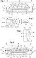
- la
figure 1 est une vue en coupe d'un exemple de réalisation d'une télécommande pour véhicule conforme à l'invention ; - la
figure 2 est une représentation schématique de la télécommande de lafigure 1 en communication avec un véhicule automobile ; - la
figure 3 représente un autre exemple de réalisation d'une telle télécommande ; et - la
figure 4 représente une variante de réalisation de la télécommande de lafigure 1 . - Les
figures 1 et 4 montrent une télécommande 1 ; 101 pour véhicule (ici pour véhicule automobile) conforme à l'invention. - Comme expliqué plus bas, une telle télécommande 1 ; 101 permet de commander à distance au moins une fonctionnalité (et en général plusieurs fonctionnalités) d'un véhicule 50 (schématiquement représenté en
figure 2 ), telle que le déverrouillage des portes du véhicule 50 et/ou le verrouillage des portes du véhicule 50. - La télécommande 1 ; 101 représentée sur les
figures 1 et 4 comprend une enveloppe externe 2 ; 102 formée d'une coque supérieure 4 ; 104 et d'une coque inférieure 6 ; 106 (avec interposition d'une membrane d'étanchéité 125 dans le cas de lafigure 4 , comme expliqué plus bas). - L'enveloppe externe 2 ; 102 (c'est-à-dire la coque supérieure 4 ; 104 d'une part et la coque inférieure 6 ; 106 d'autre part) est par exemple réalisée dans une matière plastique relativement rigide (de module d'Young compris typiquement entre 1 GPa et 10 GPa), telle que du polyamide (PA) ou du poly(téréphtalate de butylène) (PBT). En variante, l'enveloppe externe 2 ; 102 pourrait être réalisée dans une matière métallique, telle que de l'aluminium ou du zamak. Par ailleurs, selon une possibilité de réalisation, l'enveloppe externe 2 ; 102 pourrait contenir au moins une pièce de décoration réalisée dans une matière distincte, tel que du cuir, du bois ou un autre type de plastique (l'enveloppe externe pouvant dans ce cas être formé en bi-injection).
- La coque supérieure 4 ; 104 définit, sur sa surface externe et au niveau d'une région centrale C, une surface d'appui S déformable (du fait notamment de l'épaisseur de matériau utilisée), généralement plane, destiné à recevoir des sollicitations de l'utilisateur de la télécommande 1 ; 101 comme expliqué plus loin.
- La coque supérieure 4 ; 104 présente par ailleurs une région périphérique annulaire P à partir de laquelle s'étend (en direction de la coque inférieure 6 ; 106) un muret périphérique 3 ; 103 dont l'extrémité vient au contact de la coque inférieure 6 (avec interposition de la membrane d'étanchéité 125 sur une partie au moins de cette extrémité dans le cas de la
figure 4 ). - La région centrale C (qui porte la surface d'appui S), la région périphérique P et le muret 3 sont ici réalisés d'une pièce, par exemple par injection de la matière plastique précitée.
- En particulier, la région centrale C portant la surface d'appui S et la région périphérique P sont reliées entre elles avec continuité de matière. La face de la coque supérieure 4 ; 104 portant la surface d'appui S ne présente d'ailleurs aucune interruption ou discontinuité de matière.
- Du fait de cette continuité de matière, on peut prévoir en pratique de délimiter la surface d'appui S et la région périphérique P au moyen d'un motif de décor (apposé sur la face externe de la coque supérieure 4 ; 104) ou d'un relief (formé au niveau de la face externe de la coque supérieure 4 ; 104), ce afin de permettre à l'utilisateur de discerner cette surface d'appui S.
- Selon un mode de réalisation envisageable, des motifs de décor transparents pourraient être prévus sur la surface d'appui S (la coque supérieure 4 ; 104 étant opaque en dehors de ces motif de décor transparents) ; ces motifs de décors pourraient être rétroéclairés par un dispositif d'éclairage (par exemple des diodes électroluminescentes) prévu au sein de la télécommande 1 ; 101 (par exemple monté sur le circuit imprimé 20 ; 120).
- La face de la coque supérieure 4 ; 104 portant la surface d'appui S s'étend ainsi sur tout le côté concerné de la télécommande 1 ; 101. Autrement dit, les dimensions de la face de la coque supérieure 4 ; 104 portant la surface d'appui S correspondent ici aux dimensions extérieures de la télécommande 1 ; 101.
- La coque inférieure 6 ; 106 comprend quant à elle une paroi de fond 8 ; 108 et une paroi interne 10 ; 119 reliées par des parois latérales 12 ; 112 de sorte à définir un logement 14 ; 114 pour une batterie électrique 16 ; 116.
- La coque inférieure 6 ; 106 comprend également une paroi périphérique externe 18 ; 118 qui s'étend à partir de la paroi de fond 8 ; 108 en direction de la coque supérieure 4 ; 104, jusqu'au contact du muret 3 ; 103 susmentionné (avec interposition de la membrane d'étanchéité 125 sur une partie au moins de l'épaisseur du muret 103 et de la paroi périphérique externe 118 dans le cas de la
figure 4 ). - La coque supérieure 4 ; 104 et la coque inférieure 6 ; 106 forment ainsi une enveloppe externe 2 ; 102 étanche renfermant des circuits électriques et électroniques comme décrit ci-après. Dans le cas de la
figure 4 , la coque inférieure 106 et la membrane d'étanchéité 125 forment en outre des parois étanches pour un volume renfermant les circuits électriques et électroniques. - La coque inférieure 6 ; 106 (précisément la paroi interne 10 ; 110) porte un circuit imprimé 20 ; 120 alimenté électriquement par la batterie électrique 16 ; 116.
- Comme schématiquement représenté sur la
figure 1 , le circuit imprimé 20 ; 120 porte un processeur 22 ; 122 et un module de communication 24 ; 124. - Le circuit imprimé 20 ; 120 porte également au moins un capteur de force, ici deux capteurs de forces 30, 40 ; 130, 140.
- Chaque capteur de force 30, 40 est couplé mécaniquement à la région centrale C formant la surface d'appui S, avec interposition d'un bloc élastomère 32, 42 dans le cas de la
figure 1 ou avec interposition de la membrane 125 dans le cas de lafigure 4 . - Les capteurs de force 30, 40 peuvent être sollicités du fait d'une déformation (ici une microdéformation) de la surface d'appui S (l'absence de discontinuité au niveau de la face de la coque supérieure 4 ; 104 portant la surface d'appui S empêchant tout mouvement relatif de deux parties de la surface d'appui, sauf par déformation).
- La
figure 2 donne une représentation schématique de la télécommande 1 ; 101 en communication avec une unité électronique de commande 52 du véhicule 50. - Comme représenté sur cette figure, le processeur 22 ; 122 est relié d'une part à chacun des capteurs de force 30, 40 ; 130, 140 de sorte à recevoir des valeurs d'effort mesurées par les capteurs de force 30, 40 ; 130, 140 et à déterminer les efforts exercés respectivement sur une pluralité de zones Z1, Z2, Z3 de la région centrale C formant la surface d'appui S.
- Le processeur 22 ; 122 est d'autre part relié au module de communication 24 ; 124 de manière à commander l'émission par ce module de communication 24; 124 de signaux électromagnétiques (ici en pratique de signaux radiofréquences) destinées à l'unité électronique de commande 52 du véhicule 50, comme décrit plus bas.
- Le processeur 22 ; 122 (par exemple un microcontrôleur) comprend au moins une mémoire (non représentée, par exemple une mémoire non-volatile réinscriptible) qui mémorise des instructions de programme d'ordinateur conçues pour mettre en oeuvre le fonctionnement du processeur 22 ; 122 (notamment comme décrit dans la présente description) lorsque ces instructions sont exécutées par le processeur 22 ; 122.
- La mémoire du processeur 22 ; 122 mémorise par ailleurs une table associant, pour chaque zone Z1, Z2, Z3 de la surface d'appui S, au moins une commande à émettre à une plage de valeurs d'effort déterminées au niveau de la zone Z1, Z2, Z3 concernée.
- Lorsqu'un utilisateur exerce un effort sur la surface d'appui S au niveau d'une zone Z1, Z2, Z3, l'enveloppe externe 2 subit une microdéformation et le processeur 22 ; 122 détermine ainsi, sur la base des mesures réalisées par les capteurs de force 30, 40, l'effort ainsi exercé au niveau de la zone Z1, Z2, Z3 concernée.
- Le processeur 22 ; 122 peut ainsi déterminer éventuellement une commande associée à la valeur d'effort déterminée (ici par comparaison de la valeur d'effort déterminée aux différentes plages de valeurs mémorisées dans la table précitée pour la zone Z1 ; Z2 ; Z3 concernée, puis par sélection de la commande associée dans la table précitée à la plage de valeurs qui correspond à la valeur d'effort déterminée pour la zone Z1 ; Z2 ; Z3 concernée).
- Selon une première possibilité de réalisation, une seule commande est prévue pour chaque zone Z1 ; Z2 ; Z3 de la surface d'appui S, 40, en association avec une plage de valeurs définie au-dessus d'un seuil prédéterminé.
- Dans un tel cas, tant que l'effort déterminée par le processeur 22 ; 122 pour la zone Z1 ; Z2 ; Z3 concernée (sur la base des mesures effectuées par les capteurs de force 30, 40 ; 130, 140) est inférieur au seuil prédéterminé, aucune commande n'est associée (par le processeur 2 ; 122) à l'effort déterminé et aucune commande n'est émise par la télécommande 1 ; 101.
- En revanche, dès lors que l'effort déterminé par le processeur 22 ; 122 pour la zone Z1 ; Z2 ; Z3 concernée (sur la base des mesures effectuées par les capteurs de force 30, 40 ; 130, 150) est supérieur au seuil prédéterminé, la commande prévue pour la zone Z1 ; Z2 ; Z3 concernée est sélectionnée par le processeur 22 ; 122 (ici par lecture de la table précitée mémorisée dans la mémoire du processeur 22 ; 122) et le processeur 22 ; 122 commande au module de communication 24 ; 124 l'émission d'un signal électromagnétique associé à la commande sélectionnée.
- Selon une seconde possibilité de réalisation, plusieurs commandes sont prévues pour au moins une zone Z1 ; Z2 ; Z3 de la surface d'appui S, chaque commande étant associée à une plage de valeurs spécifique de l'effort déterminé par le processeur 22 ; 122 pour cette zone Z1 ; Z2 ; Z3 (sur la base des mesures effectuées par les capteurs de force 30, 40 ; 130, 140).
- Ainsi, si l'utilisateur exerce un effort compris dans une première plage de valeurs sur la zone Z1 ; Z2 ; Z3 concernée, le processeur 22 ; 122 détermine une première commande associée à cette première plage de valeurs (ici par consultation de la table mémorisée dans la mémoire du processeur 22 ; 122) et commande au module de communication 24 ; 124 l'émission d'un premier signal électromagnétique associé à cette première commande. Une telle première commande est par exemple une commande de déverrouillage des portes du véhicule 50.
- De même, si l'utilisateur exerce un effort compris dans une seconde plage de valeurs (distincte de la première plage de valeurs) sur la zone Z1 ; Z2 ; Z3 concernée, le processeur 22 ; 122 détermine une seconde commande associée à cette seconde plage de valeurs (ici par consultation de la table mémorisée dans la mémoire du processeur 22 ; 122) et commande au module de communication 24 ; 124 l'émission d'un second signal électromagnétique associé à cette seconde commande. Une telle seconde commande est par exemple une commande de verrouillage des portes du véhicule 50.
- Dans tous les cas mentionnés ci-dessus, l'unité électronique de commande 52 du véhicule 50 reçoit le signal électromagnétiques émis par le module de communication 24 ; 124 et met alors en oeuvre la commande associée à ce signal électromagnétique, par exemple en commandant à un système de verrouillage (non représenté) du véhicule 50 le verrouillage ou le déverrouillage (le cas échéant) du véhicule 50 dans les exemples précités.
- Selon un mode de réalisation envisageable, la télécommande 1 ; 101 peut être conçue pour fonctionner soit dans un mode de veille (à basse consommation), soit dans un mode actif, et comprendre un détecteur de mouvement (tel qu'un accéléromètre, par exemple implanté sur le circuit imprimé 20 ; 120)
- Lorsque la télécommande 1 est en mode veille et que le détecteur de mouvement détecte un mouvement, la télécommande 1 bascule en mode actif, où les composants mentionnés ci-dessus (en particulier le processeur 22 ; 122 et les capteurs de force 30, 40 ; 130, 140) sont opérationnels et peuvent ainsi fonctionner comme décrit plus haut.
- Par ailleurs, après un laps de temps prédéterminé en mode actif sans détection d'effort par les capteurs de force 30, 40 ; 130, 140 et/ou sans détection de mouvement par le détecteur de mouvement, la télécommande 1 ; 101 bascule en mode veille (où le processeur 22 ; 122 et/ou les capteurs de force 30, 40 ; 130, 140 ont une consommation réduite, voire nulle).
- En variante, le basculement du mode de veille au mode actif pourrait être déclenché par actionnement (par l'utilisateur) d'un bouton prévu sur la télécommande 1 ; 101 ou au moyen d'un système de reconnaissance biométrique (par exemple un système de reconnaissance d'empreintes digitales).
- Dans le cas où un dispositif d'éclairage de motifs de décor translucides est prévu comme proposé ci-dessus, ce dispositif d'éclairage est actif (c'est-à-dire éclaire les motifs de décor translucides) lorsque la télécommande 1 ; 101 est en mode actif, et éteint lorsque la télécommande est en mode de veille.
- Selon un autre mode de réalisation envisageable (éventuellement combinable avec la possibilité présentée ci-dessus), la télécommande 1 ; 101 peut comprendre un indicateur (non représenté) qui permet de fournir un retour à l'utilisateur suite à la détermination d'une commande par le processeur 22 ; 122.
- Un tel indicateur peut être un indicateur haptique (par exemple un vibreur monté au sein de la télécommande 1 ; 101), un indicateur lumineux (par exemple au moins une diode électroluminescente implantée au sein de la télécommande 1, éventuellement sur le circuit imprimé 20 ; 120) ou un indicateur sonore (réalisé par exemple au moyen d'un transducteur électro-acoustique).
- Le processeur 22 ; 122 peut commander, suite à la détermination d'une commande en fonction de l'effort déterminé sur la base des valeurs mesurées par les capteurs de force 30, 40 ; 130, 140 comme déjà expliqué, l'émission d'un signal par l'indicateur (à savoir une vibration dans le cas de l'indicateur haptique, un signal lumineux dans le cas d'un indicateur lumineux et un signal sonore dans le cas de l'indicateur sonore).
- Dans le cas où plusieurs commandes peuvent être ainsi déterminées par le processeur 22 ; 122 comme expliqué plus haut, le processeur 22 ; 122 peut commander l'émission par l'indicateur d'un signal (choisi parmi différents signaux) associé à la commande déterminée.
- La
figure 3 représente un autre exemple de réalisation d'une télécommande 60 conforme à l'invention. - La télécommande 60 comprend tous les éléments de la télécommande 1 décrite ci-dessus (y compris les deux capteurs de force 30, 40) et ne sera donc pas décrit en détail.
- La télécommande 60 comprend en outre une pluralité de capteurs de force 62, 64, 66, 68 situés dans la même région 70 de la surface d'appui S.
- Les capteurs de force 62, 64, 66, 68 sont disposés selon une ligne (ici une ligne courbe) de sorte que le passage d'un doigt de l'utilisateur sur la surface d'appui S au niveau de la région 70 et selon cette ligne (comme représenté par la flèche F sur la
figure 3 ) est détecté successivement par chacun des capteurs de force 62, 64, 66, 68. - Ainsi, lorsque les différents capteurs de force 62, 64, 66, 68 transmettent successivement au processeur 22 (dans un ordre prédéfini des capteurs 62, 64, 66, 68) une valeur d'effort mesuré supérieure à une valeur seuil (de sorte que le processeur 22 détecte l'actionnement successif de ces capteurs de force 62, 64, 66, 68), le processeur 22 en déduit le passage du doigt de l'utilisateur selon la ligne formée par les capteurs 62, 64, 66, 68 et peut mettre en oeuvre une action associée à ce mouvement.
- Selon une première possibilité de réalisation, cette action est le basculement de la télécommande 1 d'un premier mode de fonctionnement (où les autres capteurs de force 30, 40 sont par exemple inactifs et/ou le dispositif d'éclairage mentionné plus haut est éteint) vers un second mode de fonctionnement (où les autres capteurs de force 30, 40 sont actifs et/ou le dispositif d'éclairage mentionné plus haut est actif).
- Selon une seconde possibilité de réalisation, cette action est la détermination d'une commande à émettre associée à ce mouvement et l'émission d'un signal électromagnétique associé à cette commande.
Claims (12)
- Télécommande (1 ; 101) pour véhicule (50) comprenant :- une enveloppe externe (2 ; 102) définissant une surface d'appui (S) déformable ;- au moins un capteur de force (30 ; 40 ; 130 ; 140) couplé à l'enveloppe externe (2 ; 102) de sorte à mesurer un effort exercé sur la surface d'appui (S) ;- un processeur (22 ; 122) conçu pour déterminer un effort exercé sur une zone (Z1 ; Z2 ; Z3) de la surface d'appui en fonction de l'effort mesuré et pour déterminer une commande à émettre en fonction de l'effort déterminé ; et- un module de communication (24 ; 124) conçu pour émettre un signal électromagnétique associé à la commande déterminée.
- Télécommande selon la revendication 1, dans laquelle le processeur (22 ; 122) est conçu pour sélectionner une première commande lorsque l'effort déterminé est compris dans une première plage de valeurs et pour sélectionner une seconde commande lorsque l'effort déterminé est compris dans une seconde plage de valeurs distincte de la première plage de valeurs.
- Télécommande selon la revendication 1 ou 2, dans laquelle l'enveloppe externe (2 ; 102) comprend une coque inférieure (6 ; 106) agencée pour recevoir une batterie électrique (16 ; 116) et une coque supérieure (4 ; 104) portant la surface d'appui (S).
- Télécommande selon la revendication 3, comprenant une membrane d'étanchéité (125) interposée d'une part entre le capteur de force (130 ; 140) et l'enveloppe externe (102), et d'autre part entre la coque inférieure (106) et la coque supérieure (104).
- Télécommande selon l'une des revendications 1 à 3, dans laquelle un bloc élastomère (32 ; 42) est interposé entre le capteur de force (30 ; 40) et l'enveloppe externe (2).
- Télécommande selon l'une des revendications 1 à 5, comprenant un détecteur de mouvement et conçue pour basculer d'un mode de veille à un mode actif lorsque le détecteur de mouvement détecte un mouvement.
- Télécommande selon l'une des revendications 1 à 5, comprenant un bouton et conçue pour basculer d'un mode de veille à un mode actif en cas d'actionnement du bouton.
- Télécommande selon l'une des revendications 1 à 7, dans laquelle le processeur est conçu pour commander l'émission d'un signal par un indicateur lorsque la commande à émettre est déterminée.
- Télécommande selon la revendication 8, dans laquelle l'indicateur est un indicateur haptique.
- Télécommande selon la revendication 8, dans laquelle l'indicateur est un indicateur lumineux.
- Télécommande selon l'une des revendications 1 à 10, comprenant une pluralité de capteurs de force (62, 64, 66, 68).
- Télécommande selon la revendication 11, dans laquelle le processeur (22) est conçu pour détecter l'actionnement successif de certains capteurs de force au moins (62, 64, 66, 68) parmi les capteurs de force de ladite pluralité.
Applications Claiming Priority (1)
| Application Number | Priority Date | Filing Date | Title |
|---|---|---|---|
| FR1762792A FR3076044B1 (fr) | 2017-12-21 | 2017-12-21 | Telecommande pour vehicule |
Publications (2)
| Publication Number | Publication Date |
|---|---|
| EP3503064A1 true EP3503064A1 (fr) | 2019-06-26 |
| EP3503064B1 EP3503064B1 (fr) | 2024-03-13 |
Family
ID=62067624
Family Applications (1)
| Application Number | Title | Priority Date | Filing Date |
|---|---|---|---|
| EP18213207.6A Active EP3503064B1 (fr) | 2017-12-21 | 2018-12-17 | Télécommande pour véhicule |
Country Status (2)
| Country | Link |
|---|---|
| EP (1) | EP3503064B1 (fr) |
| FR (1) | FR3076044B1 (fr) |
Citations (4)
| Publication number | Priority date | Publication date | Assignee | Title |
|---|---|---|---|---|
| US20030227406A1 (en) * | 2002-06-05 | 2003-12-11 | Armstrong Brad A. | Remote controller with analog button(s) |
| US20110267294A1 (en) * | 2010-04-29 | 2011-11-03 | Nokia Corporation | Apparatus and method for providing tactile feedback for user |
| WO2013100324A1 (fr) * | 2011-12-28 | 2013-07-04 | Coway Co., Ltd. | Dispositif d'entrée basé sur un capteur de force et bidet comportant un tel dispositif |
| US20160278229A1 (en) * | 2013-10-30 | 2016-09-22 | Denso Corporation | Portable wireless key |
-
2017
- 2017-12-21 FR FR1762792A patent/FR3076044B1/fr active Active
-
2018
- 2018-12-17 EP EP18213207.6A patent/EP3503064B1/fr active Active
Patent Citations (4)
| Publication number | Priority date | Publication date | Assignee | Title |
|---|---|---|---|---|
| US20030227406A1 (en) * | 2002-06-05 | 2003-12-11 | Armstrong Brad A. | Remote controller with analog button(s) |
| US20110267294A1 (en) * | 2010-04-29 | 2011-11-03 | Nokia Corporation | Apparatus and method for providing tactile feedback for user |
| WO2013100324A1 (fr) * | 2011-12-28 | 2013-07-04 | Coway Co., Ltd. | Dispositif d'entrée basé sur un capteur de force et bidet comportant un tel dispositif |
| US20160278229A1 (en) * | 2013-10-30 | 2016-09-22 | Denso Corporation | Portable wireless key |
Also Published As
| Publication number | Publication date |
|---|---|
| EP3503064B1 (fr) | 2024-03-13 |
| FR3076044B1 (fr) | 2020-07-10 |
| FR3076044A1 (fr) | 2019-06-28 |
Similar Documents
| Publication | Publication Date | Title |
|---|---|---|
| EP2109869B1 (fr) | Dispositif de commande électrique | |
| EP0597753B1 (fr) | Terminal de communication compact et ergonomique muni de surfaces de détection de proximité | |
| WO2011061281A2 (fr) | Dispositif de commande de déverrouillage de véhicule muni d'un organe de commande externe à support surmoulé | |
| FR2917859A1 (fr) | Dispositif de commande electrique | |
| FR2876406A1 (fr) | Installation de controle d'acces a commande acoustique et dispositif de controle d'acces pour une telle installation | |
| EP2487661B1 (fr) | Télécommande sans fil à interface tactile pour équipement multimedia et de téléphonie mains-libres de véhicule automobile | |
| WO2003012230A1 (fr) | Poignee d'ouvrant pour vehicule automobile | |
| WO2008135129A2 (fr) | Dispositif de suppression du phénomène d'interférences entre zones de détection capacitives d'un capteur | |
| WO2008145716A1 (fr) | Dispositif de commande tactile à retour haptique | |
| WO2019234238A1 (fr) | Dispositif de détection d'intention de verrouillage ou de déverrouillage d'un ouvrant de véhicule automobile avec électrode ou cible supportée par un bloc de mousse | |
| EP3404506A1 (fr) | Panneau de commande pour vehicule automobile | |
| FR3096712A1 (fr) | Capteur capacitif pour vehicule automobile | |
| EP2067922B1 (fr) | Système de rideau roulant | |
| EP3503064B1 (fr) | Télécommande pour véhicule | |
| WO2003015049A1 (fr) | Perfectionnement pour telecommande a changement de mode de fonctionnement | |
| FR2781246A1 (fr) | Systeme de securite pour un ouvrant de vehicule automobile comportant des moyens de raccordement perfectionnes | |
| FR2989411A1 (fr) | Dispositif de commande de l'ouverture d'une porte. | |
| FR3079047A1 (fr) | Module de commande de porte, ensemble de commande de porte et porte de vehicule associes | |
| FR3059945B1 (fr) | Dispositif de commande en particulier pour vehicule | |
| EP2845771B1 (fr) | Ensemble structurel de véhicule automobile | |
| WO2007121817A1 (fr) | Dispositif de detection de mouvement d’une poignee de portiere de vehicule automobile | |
| FR2627883A3 (fr) | Radiocommande portative pour grilles, portails, boxes et similaires | |
| EP2096653A1 (fr) | Module de commande électrique | |
| EP1685996B1 (fr) | Véhicule automobile possedant une face d'un ouvrant recouverte d'une feuille sensible à la pression | |
| FR2865445A1 (fr) | Dispositif de controle d'acces et / ou de demarrage d'un vehicule automobile |
Legal Events
| Date | Code | Title | Description |
|---|---|---|---|
| PUAI | Public reference made under article 153(3) epc to a published international application that has entered the european phase |
Free format text: ORIGINAL CODE: 0009012 |
|
| STAA | Information on the status of an ep patent application or granted ep patent |
Free format text: STATUS: THE APPLICATION HAS BEEN PUBLISHED |
|
| AK | Designated contracting states |
Kind code of ref document: A1 Designated state(s): AL AT BE BG CH CY CZ DE DK EE ES FI FR GB GR HR HU IE IS IT LI LT LU LV MC MK MT NL NO PL PT RO RS SE SI SK SM TR |
|
| AX | Request for extension of the european patent |
Extension state: BA ME |
|
| STAA | Information on the status of an ep patent application or granted ep patent |
Free format text: STATUS: REQUEST FOR EXAMINATION WAS MADE |
|
| 17P | Request for examination filed |
Effective date: 20191218 |
|
| RBV | Designated contracting states (corrected) |
Designated state(s): AL AT BE BG CH CY CZ DE DK EE ES FI FR GB GR HR HU IE IS IT LI LT LU LV MC MK MT NL NO PL PT RO RS SE SI SK SM TR |
|
| STAA | Information on the status of an ep patent application or granted ep patent |
Free format text: STATUS: EXAMINATION IS IN PROGRESS |
|
| 17Q | First examination report despatched |
Effective date: 20200709 |
|
| RAP3 | Party data changed (applicant data changed or rights of an application transferred) |
Owner name: VALEO COMFORT AND DRIVING ASSISTANCE |
|
| P01 | Opt-out of the competence of the unified patent court (upc) registered |
Effective date: 20230528 |
|
| GRAP | Despatch of communication of intention to grant a patent |
Free format text: ORIGINAL CODE: EPIDOSNIGR1 |
|
| STAA | Information on the status of an ep patent application or granted ep patent |
Free format text: STATUS: GRANT OF PATENT IS INTENDED |
|
| INTG | Intention to grant announced |
Effective date: 20230807 |
|
| GRAJ | Information related to disapproval of communication of intention to grant by the applicant or resumption of examination proceedings by the epo deleted |
Free format text: ORIGINAL CODE: EPIDOSDIGR1 |
|
| STAA | Information on the status of an ep patent application or granted ep patent |
Free format text: STATUS: EXAMINATION IS IN PROGRESS |
|
| GRAP | Despatch of communication of intention to grant a patent |
Free format text: ORIGINAL CODE: EPIDOSNIGR1 |
|
| STAA | Information on the status of an ep patent application or granted ep patent |
Free format text: STATUS: GRANT OF PATENT IS INTENDED |
|
| INTC | Intention to grant announced (deleted) | ||
| INTG | Intention to grant announced |
Effective date: 20231113 |
|
| RAP3 | Party data changed (applicant data changed or rights of an application transferred) |
Owner name: VALEO COMFORT AND DRIVING ASSISTANCE |
|
| GRAS | Grant fee paid |
Free format text: ORIGINAL CODE: EPIDOSNIGR3 |
|
| GRAA | (expected) grant |
Free format text: ORIGINAL CODE: 0009210 |
|
| STAA | Information on the status of an ep patent application or granted ep patent |
Free format text: STATUS: THE PATENT HAS BEEN GRANTED |
|
| AK | Designated contracting states |
Kind code of ref document: B1 Designated state(s): AL AT BE BG CH CY CZ DE DK EE ES FI FR GB GR HR HU IE IS IT LI LT LU LV MC MK MT NL NO PL PT RO RS SE SI SK SM TR |
|
| REG | Reference to a national code |
Ref country code: GB Ref legal event code: FG4D Free format text: NOT ENGLISH |
|
| REG | Reference to a national code |
Ref country code: CH Ref legal event code: EP |
|
| REG | Reference to a national code |
Ref country code: DE Ref legal event code: R096 Ref document number: 602018066519 Country of ref document: DE |
|
| REG | Reference to a national code |
Ref country code: IE Ref legal event code: FG4D Free format text: LANGUAGE OF EP DOCUMENT: FRENCH |
|
| PG25 | Lapsed in a contracting state [announced via postgrant information from national office to epo] |
Ref country code: LT Free format text: LAPSE BECAUSE OF FAILURE TO SUBMIT A TRANSLATION OF THE DESCRIPTION OR TO PAY THE FEE WITHIN THE PRESCRIBED TIME-LIMIT Effective date: 20240313 |
|
| REG | Reference to a national code |
Ref country code: LT Ref legal event code: MG9D |
|
| PG25 | Lapsed in a contracting state [announced via postgrant information from national office to epo] |
Ref country code: GR Free format text: LAPSE BECAUSE OF FAILURE TO SUBMIT A TRANSLATION OF THE DESCRIPTION OR TO PAY THE FEE WITHIN THE PRESCRIBED TIME-LIMIT Effective date: 20240614 |
|
| REG | Reference to a national code |
Ref country code: NL Ref legal event code: MP Effective date: 20240313 |
|
| PG25 | Lapsed in a contracting state [announced via postgrant information from national office to epo] |
Ref country code: RS Free format text: LAPSE BECAUSE OF FAILURE TO SUBMIT A TRANSLATION OF THE DESCRIPTION OR TO PAY THE FEE WITHIN THE PRESCRIBED TIME-LIMIT Effective date: 20240613 Ref country code: HR Free format text: LAPSE BECAUSE OF FAILURE TO SUBMIT A TRANSLATION OF THE DESCRIPTION OR TO PAY THE FEE WITHIN THE PRESCRIBED TIME-LIMIT Effective date: 20240313 |
|
| PG25 | Lapsed in a contracting state [announced via postgrant information from national office to epo] |
Ref country code: ES Free format text: LAPSE BECAUSE OF FAILURE TO SUBMIT A TRANSLATION OF THE DESCRIPTION OR TO PAY THE FEE WITHIN THE PRESCRIBED TIME-LIMIT Effective date: 20240313 |
|
| PG25 | Lapsed in a contracting state [announced via postgrant information from national office to epo] |
Ref country code: RS Free format text: LAPSE BECAUSE OF FAILURE TO SUBMIT A TRANSLATION OF THE DESCRIPTION OR TO PAY THE FEE WITHIN THE PRESCRIBED TIME-LIMIT Effective date: 20240613 Ref country code: NO Free format text: LAPSE BECAUSE OF FAILURE TO SUBMIT A TRANSLATION OF THE DESCRIPTION OR TO PAY THE FEE WITHIN THE PRESCRIBED TIME-LIMIT Effective date: 20240613 Ref country code: LT Free format text: LAPSE BECAUSE OF FAILURE TO SUBMIT A TRANSLATION OF THE DESCRIPTION OR TO PAY THE FEE WITHIN THE PRESCRIBED TIME-LIMIT Effective date: 20240313 Ref country code: HR Free format text: LAPSE BECAUSE OF FAILURE TO SUBMIT A TRANSLATION OF THE DESCRIPTION OR TO PAY THE FEE WITHIN THE PRESCRIBED TIME-LIMIT Effective date: 20240313 Ref country code: GR Free format text: LAPSE BECAUSE OF FAILURE TO SUBMIT A TRANSLATION OF THE DESCRIPTION OR TO PAY THE FEE WITHIN THE PRESCRIBED TIME-LIMIT Effective date: 20240614 Ref country code: FI Free format text: LAPSE BECAUSE OF FAILURE TO SUBMIT A TRANSLATION OF THE DESCRIPTION OR TO PAY THE FEE WITHIN THE PRESCRIBED TIME-LIMIT Effective date: 20240313 Ref country code: ES Free format text: LAPSE BECAUSE OF FAILURE TO SUBMIT A TRANSLATION OF THE DESCRIPTION OR TO PAY THE FEE WITHIN THE PRESCRIBED TIME-LIMIT Effective date: 20240313 Ref country code: BG Free format text: LAPSE BECAUSE OF FAILURE TO SUBMIT A TRANSLATION OF THE DESCRIPTION OR TO PAY THE FEE WITHIN THE PRESCRIBED TIME-LIMIT Effective date: 20240313 |
|
| REG | Reference to a national code |
Ref country code: AT Ref legal event code: MK05 Ref document number: 1666511 Country of ref document: AT Kind code of ref document: T Effective date: 20240313 |
|
| PG25 | Lapsed in a contracting state [announced via postgrant information from national office to epo] |
Ref country code: SE Free format text: LAPSE BECAUSE OF FAILURE TO SUBMIT A TRANSLATION OF THE DESCRIPTION OR TO PAY THE FEE WITHIN THE PRESCRIBED TIME-LIMIT Effective date: 20240313 Ref country code: LV Free format text: LAPSE BECAUSE OF FAILURE TO SUBMIT A TRANSLATION OF THE DESCRIPTION OR TO PAY THE FEE WITHIN THE PRESCRIBED TIME-LIMIT Effective date: 20240313 |
|
| PG25 | Lapsed in a contracting state [announced via postgrant information from national office to epo] |
Ref country code: NL Free format text: LAPSE BECAUSE OF FAILURE TO SUBMIT A TRANSLATION OF THE DESCRIPTION OR TO PAY THE FEE WITHIN THE PRESCRIBED TIME-LIMIT Effective date: 20240313 |
|
| PG25 | Lapsed in a contracting state [announced via postgrant information from national office to epo] |
Ref country code: NL Free format text: LAPSE BECAUSE OF FAILURE TO SUBMIT A TRANSLATION OF THE DESCRIPTION OR TO PAY THE FEE WITHIN THE PRESCRIBED TIME-LIMIT Effective date: 20240313 |
|
| PG25 | Lapsed in a contracting state [announced via postgrant information from national office to epo] |
Ref country code: IS Free format text: LAPSE BECAUSE OF FAILURE TO SUBMIT A TRANSLATION OF THE DESCRIPTION OR TO PAY THE FEE WITHIN THE PRESCRIBED TIME-LIMIT Effective date: 20240713 |
|
| PG25 | Lapsed in a contracting state [announced via postgrant information from national office to epo] |
Ref country code: PT Free format text: LAPSE BECAUSE OF FAILURE TO SUBMIT A TRANSLATION OF THE DESCRIPTION OR TO PAY THE FEE WITHIN THE PRESCRIBED TIME-LIMIT Effective date: 20240715 Ref country code: SM Free format text: LAPSE BECAUSE OF FAILURE TO SUBMIT A TRANSLATION OF THE DESCRIPTION OR TO PAY THE FEE WITHIN THE PRESCRIBED TIME-LIMIT Effective date: 20240313 |
|
| PG25 | Lapsed in a contracting state [announced via postgrant information from national office to epo] |
Ref country code: CZ Free format text: LAPSE BECAUSE OF FAILURE TO SUBMIT A TRANSLATION OF THE DESCRIPTION OR TO PAY THE FEE WITHIN THE PRESCRIBED TIME-LIMIT Effective date: 20240313 Ref country code: EE Free format text: LAPSE BECAUSE OF FAILURE TO SUBMIT A TRANSLATION OF THE DESCRIPTION OR TO PAY THE FEE WITHIN THE PRESCRIBED TIME-LIMIT Effective date: 20240313 |
|
| PG25 | Lapsed in a contracting state [announced via postgrant information from national office to epo] |
Ref country code: AT Free format text: LAPSE BECAUSE OF FAILURE TO SUBMIT A TRANSLATION OF THE DESCRIPTION OR TO PAY THE FEE WITHIN THE PRESCRIBED TIME-LIMIT Effective date: 20240313 |
|
| PG25 | Lapsed in a contracting state [announced via postgrant information from national office to epo] |
Ref country code: PL Free format text: LAPSE BECAUSE OF FAILURE TO SUBMIT A TRANSLATION OF THE DESCRIPTION OR TO PAY THE FEE WITHIN THE PRESCRIBED TIME-LIMIT Effective date: 20240313 |
|
| PG25 | Lapsed in a contracting state [announced via postgrant information from national office to epo] |
Ref country code: SK Free format text: LAPSE BECAUSE OF FAILURE TO SUBMIT A TRANSLATION OF THE DESCRIPTION OR TO PAY THE FEE WITHIN THE PRESCRIBED TIME-LIMIT Effective date: 20240313 |
|
| PG25 | Lapsed in a contracting state [announced via postgrant information from national office to epo] |
Ref country code: SM Free format text: LAPSE BECAUSE OF FAILURE TO SUBMIT A TRANSLATION OF THE DESCRIPTION OR TO PAY THE FEE WITHIN THE PRESCRIBED TIME-LIMIT Effective date: 20240313 Ref country code: SK Free format text: LAPSE BECAUSE OF FAILURE TO SUBMIT A TRANSLATION OF THE DESCRIPTION OR TO PAY THE FEE WITHIN THE PRESCRIBED TIME-LIMIT Effective date: 20240313 Ref country code: RO Free format text: LAPSE BECAUSE OF FAILURE TO SUBMIT A TRANSLATION OF THE DESCRIPTION OR TO PAY THE FEE WITHIN THE PRESCRIBED TIME-LIMIT Effective date: 20240313 Ref country code: PT Free format text: LAPSE BECAUSE OF FAILURE TO SUBMIT A TRANSLATION OF THE DESCRIPTION OR TO PAY THE FEE WITHIN THE PRESCRIBED TIME-LIMIT Effective date: 20240715 Ref country code: PL Free format text: LAPSE BECAUSE OF FAILURE TO SUBMIT A TRANSLATION OF THE DESCRIPTION OR TO PAY THE FEE WITHIN THE PRESCRIBED TIME-LIMIT Effective date: 20240313 Ref country code: IS Free format text: LAPSE BECAUSE OF FAILURE TO SUBMIT A TRANSLATION OF THE DESCRIPTION OR TO PAY THE FEE WITHIN THE PRESCRIBED TIME-LIMIT Effective date: 20240713 Ref country code: EE Free format text: LAPSE BECAUSE OF FAILURE TO SUBMIT A TRANSLATION OF THE DESCRIPTION OR TO PAY THE FEE WITHIN THE PRESCRIBED TIME-LIMIT Effective date: 20240313 Ref country code: CZ Free format text: LAPSE BECAUSE OF FAILURE TO SUBMIT A TRANSLATION OF THE DESCRIPTION OR TO PAY THE FEE WITHIN THE PRESCRIBED TIME-LIMIT Effective date: 20240313 Ref country code: AT Free format text: LAPSE BECAUSE OF FAILURE TO SUBMIT A TRANSLATION OF THE DESCRIPTION OR TO PAY THE FEE WITHIN THE PRESCRIBED TIME-LIMIT Effective date: 20240313 |
|
| PG25 | Lapsed in a contracting state [announced via postgrant information from national office to epo] |
Ref country code: IT Free format text: LAPSE BECAUSE OF FAILURE TO SUBMIT A TRANSLATION OF THE DESCRIPTION OR TO PAY THE FEE WITHIN THE PRESCRIBED TIME-LIMIT Effective date: 20240313 |
|
| REG | Reference to a national code |
Ref country code: DE Ref legal event code: R097 Ref document number: 602018066519 Country of ref document: DE |
|
| PG25 | Lapsed in a contracting state [announced via postgrant information from national office to epo] |
Ref country code: IT Free format text: LAPSE BECAUSE OF FAILURE TO SUBMIT A TRANSLATION OF THE DESCRIPTION OR TO PAY THE FEE WITHIN THE PRESCRIBED TIME-LIMIT Effective date: 20240313 |
|
| PG25 | Lapsed in a contracting state [announced via postgrant information from national office to epo] |
Ref country code: DK Free format text: LAPSE BECAUSE OF FAILURE TO SUBMIT A TRANSLATION OF THE DESCRIPTION OR TO PAY THE FEE WITHIN THE PRESCRIBED TIME-LIMIT Effective date: 20240313 |
|
| PLBE | No opposition filed within time limit |
Free format text: ORIGINAL CODE: 0009261 |
|
| STAA | Information on the status of an ep patent application or granted ep patent |
Free format text: STATUS: NO OPPOSITION FILED WITHIN TIME LIMIT |
|
| PG25 | Lapsed in a contracting state [announced via postgrant information from national office to epo] |
Ref country code: DK Free format text: LAPSE BECAUSE OF FAILURE TO SUBMIT A TRANSLATION OF THE DESCRIPTION OR TO PAY THE FEE WITHIN THE PRESCRIBED TIME-LIMIT Effective date: 20240313 |
|
| 26N | No opposition filed |
Effective date: 20241216 |
|
| PG25 | Lapsed in a contracting state [announced via postgrant information from national office to epo] |
Ref country code: SI Free format text: LAPSE BECAUSE OF FAILURE TO SUBMIT A TRANSLATION OF THE DESCRIPTION OR TO PAY THE FEE WITHIN THE PRESCRIBED TIME-LIMIT Effective date: 20240313 |
|
| REG | Reference to a national code |
Ref country code: DE Ref legal event code: R119 Ref document number: 602018066519 Country of ref document: DE |
|
| PG25 | Lapsed in a contracting state [announced via postgrant information from national office to epo] |
Ref country code: MC Free format text: LAPSE BECAUSE OF FAILURE TO SUBMIT A TRANSLATION OF THE DESCRIPTION OR TO PAY THE FEE WITHIN THE PRESCRIBED TIME-LIMIT Effective date: 20240313 |
|
| REG | Reference to a national code |
Ref country code: CH Ref legal event code: PL |
|
| PG25 | Lapsed in a contracting state [announced via postgrant information from national office to epo] |
Ref country code: LU Free format text: LAPSE BECAUSE OF NON-PAYMENT OF DUE FEES Effective date: 20241217 |
|
| GBPC | Gb: european patent ceased through non-payment of renewal fee |
Effective date: 20241217 |
|
| REG | Reference to a national code |
Ref country code: BE Ref legal event code: MM Effective date: 20241231 |
|
| PG25 | Lapsed in a contracting state [announced via postgrant information from national office to epo] |
Ref country code: DE Free format text: LAPSE BECAUSE OF NON-PAYMENT OF DUE FEES Effective date: 20250701 |
|
| PG25 | Lapsed in a contracting state [announced via postgrant information from national office to epo] |
Ref country code: GB Free format text: LAPSE BECAUSE OF NON-PAYMENT OF DUE FEES Effective date: 20241217 Ref country code: BE Free format text: LAPSE BECAUSE OF NON-PAYMENT OF DUE FEES Effective date: 20241231 |
|
| PG25 | Lapsed in a contracting state [announced via postgrant information from national office to epo] |
Ref country code: CH Free format text: LAPSE BECAUSE OF NON-PAYMENT OF DUE FEES Effective date: 20241231 |
|
| PG25 | Lapsed in a contracting state [announced via postgrant information from national office to epo] |
Ref country code: IE Free format text: LAPSE BECAUSE OF NON-PAYMENT OF DUE FEES Effective date: 20241217 |
|
| PGFP | Annual fee paid to national office [announced via postgrant information from national office to epo] |
Ref country code: FR Payment date: 20251230 Year of fee payment: 8 |