EP3502570A1 - A flue chamber - Google Patents
A flue chamber Download PDFInfo
- Publication number
- EP3502570A1 EP3502570A1 EP18195164.1A EP18195164A EP3502570A1 EP 3502570 A1 EP3502570 A1 EP 3502570A1 EP 18195164 A EP18195164 A EP 18195164A EP 3502570 A1 EP3502570 A1 EP 3502570A1
- Authority
- EP
- European Patent Office
- Prior art keywords
- intermediate wall
- opening
- flue
- flue chamber
- cooking
- Prior art date
- Legal status (The legal status is an assumption and is not a legal conclusion. Google has not performed a legal analysis and makes no representation as to the accuracy of the status listed.)
- Granted
Links
Images



Classifications
-
- F—MECHANICAL ENGINEERING; LIGHTING; HEATING; WEAPONS; BLASTING
- F24—HEATING; RANGES; VENTILATING
- F24C—DOMESTIC STOVES OR RANGES ; DETAILS OF DOMESTIC STOVES OR RANGES, OF GENERAL APPLICATION
- F24C15/00—Details
- F24C15/20—Removing cooking fumes
- F24C15/2007—Removing cooking fumes from oven cavities
Definitions
- Present invention relates to a flue chamber suitable for use in oven-type cooking devices and providing to discharge, in a reliable manner, air which is formed within the cooking compartment of the cooking device.
- Oven-type cooking devices comprise at least one cooking compartment in which cooking process takes place and which, preferably, is heated by means of a heating element.
- various gases may be formed depending on structure of the product being heated/cooked and characteristics of the heating element being used. For example, during cooking of a liquid containing food, steam is formed within the cooking compartment as a result of evaporation of the liquid.
- gases such as carbon dioxide are formed due to burning of the gas. Such gases formed within the cooking compartment may negatively affect the cooking/heating process. For that reason, said gases should be removed from the cooking compartment.
- flue structures are used to send out the gases formed within the cooking compartment.
- Said flue structures comprise a flue which communicates with the cooking compartment on one side, and communicates with the outside on the other side through a body of the cooking device.
- Flue structures used in the cooking devices enables to practically discharge gases formed within the cooking compartment.
- temperature of the gases formed within the cooking compartment is generally high (250 - 350°C)
- colour changes are caused especially at the hearth plate flue outlet region made of inox raw material.
- the present invention provides a flue chamber suitable for use in a cooking device which comprises at least one cooking compartment and at least one flue communicating with the cooking compartment on at least one side.
- Said flue chamber comprises at least one body in the form of a hollow box which has at least one opening on at least one side, and at least one discharge hole on at least another side; at least one intermediate wall which is positioned in said body, partially closes said opening, and forms a discharge line between said discharge hole and the part of the opening that is not closed by the intermediate wall; at least one insulation element located between said intermediate wall and the body or between the intermediate wall and the opening, and having heat insulating properties; and at least one connection section located in said body and connecting the body to the cooking device through the opening.
- An object of the present invention is to develop a flue chamber suitable for use in oven-type cooking devices and providing to discharge, in a reliable manner, gases which are formed within the cooking compartment of the cooking device.
- Another object of the present invention is to develop a flue chamber which prevents colour change, associated with the discharged gases, at the hearth plate surface of the cooking device made of inox raw material.
- Yet another object of the present invention is to develop a durable and reliable flue chamber.
- Cooking device P
- Cooking compartment P1 Flue
- Hearth plate P3
- Discharge hole of the hearth plate P4
- Flue chamber S
- Body (1) Opening (1a) Discharge hole (1b) Upper wall (1c) Connection section (1d) Intermediate wall (2)
- Connection lug (2a) Insulation element (3)
- Connection element (4)
- gases which are formed within the cooking compartment during the cooking process should be discharged. Discharging said gases through a flue directly communicating with the body of the cooking device may cause particularly hearth plate of the cooking device made of inox raw material to get damaged. Therefore, with the present invention, there is developed a flue chamber for use in oven-type cooking devices and providing to discharge, in a reliable manner, gases which are formed within the cooking compartment of the cooking device, and being mounted to the flue outlet.
- the flue chamber (S) is suitable for use in a cooking device (P) which comprises at least one cooking compartment (P1) and at least one flue (P2) communicating with the cooking compartment (P1) on at least one side, the flue chamber comprising at least one body (1) in the form of a hollow box which has at least one opening (1a) on at least one side, and at least one discharge hole (1b) on at least another side; at least one intermediate wall (2) which is positioned in said body (1), partially closes said opening (1a), and forms a discharge line between said discharge hole (1b) and the part of the opening (1a) that is not closed by the intermediate wall; at least one insulation element (3) located between said intermediate wall (2) and the body (1) or between the intermediate wall (2) and the opening (1a), and having heat insulating properties; and at least one connection section (1d) located in said body (1) and connecting the body (1) to the cooking device (P) through the opening.
- the intermediate wall (2) positioned within the body (1) partially closes the opening (1a) which is located in the body (1).
- a discharge line is formed between the discharge hole (1b) and the part of the opening (1a) that is not closed by the intermediate wall (2).
- At least another side of said flue (P2) which is not communicating with the cooking compartment (P1) is connected to the section of the opening (1a) that is not closed by the intermediate wall (2).
- gases formed within the cooking compartment (P1) pass, respectively, through the flue (P2), the opening (1a), the discharge line formed within the body (1), and finally the discharge hole (1b) to be sent out. While said gases are discharged in this manner, the insulation element (3) (e.g.
- a glass wool located between said intermediate wall (2) and the body (1) or between the intermediate wall (2) and the opening (1a) prevents the heat formed within the discharge line from being transferred to the cooking device (P).
- said insulation element (3) heat exchange between the section of the opening (1a) which is closed by the intermediate wall (2) and the cooking device (P) is blocked.
- hearth plate (P3) of the cooking device (P) is prevented to get damaged due to hot gases discharged from the cooking compartment (P1).
- said intermediate wall (2) is in the form of a plate which is in connection with an upper wall (1c) of said body (1) on at least one side, and is inclined (in other words, having an acute angle with the upper wall (1c)) so as to approach to said opening (1a) as it moves away from the upper wall (1c).
- said insulation element (3) is positioned at the face of the intermediate wall (2), which is in the form of a plate, facing to the opening (1a). In here, when the body (1) is connected to the cooking device (P), said insulation element (3) is between the intermediate wall (2) and the cooking device (P). By this way, a better heat insulation is provided between the cooking device (P) and the discharge line.
- said discharge hole (1b) is positioned at an upper wall (1c) of the body (1).
- said discharge hole (1b) is, preferably, aligned coaxially with the discharge hole of the hearth plate (P4).
- said intermediate wall (2) is integral with the body (1).
- the intermediate wall (2) is attachable to and detachable from the body (1).
- the flue chamber (S) comprises at least one connection lug (2a) located at the intermediate wall (2), and at least one connection element (4), preferably in the form of a screw, to connect said connection lug (2a) to the body (1). Therefore, the flue chamber (S) can be used in a simple and practical manner.
- said flue chamber (S) comprises at least one protective layer (not shown in the figures) located on the body (1) and having high thermal endurance.
- Said protective layer is preferably in the form of a dye having high temperature endurance.
Landscapes
- Engineering & Computer Science (AREA)
- Chemical & Material Sciences (AREA)
- Combustion & Propulsion (AREA)
- Mechanical Engineering (AREA)
- General Engineering & Computer Science (AREA)
- Baking, Grill, Roasting (AREA)
- Ventilation (AREA)
Abstract
Description
- Present invention relates to a flue chamber suitable for use in oven-type cooking devices and providing to discharge, in a reliable manner, air which is formed within the cooking compartment of the cooking device.
- Oven-type cooking devices comprise at least one cooking compartment in which cooking process takes place and which, preferably, is heated by means of a heating element. When a cooking or heating process is performed within said cooking compartment, various gases may be formed depending on structure of the product being heated/cooked and characteristics of the heating element being used. For example, during cooking of a liquid containing food, steam is formed within the cooking compartment as a result of evaporation of the liquid. In addition to this, for example if a gas heater is used, gases such as carbon dioxide are formed due to burning of the gas. Such gases formed within the cooking compartment may negatively affect the cooking/heating process. For that reason, said gases should be removed from the cooking compartment.
- In the known art, flue structures are used to send out the gases formed within the cooking compartment. Said flue structures comprise a flue which communicates with the cooking compartment on one side, and communicates with the outside on the other side through a body of the cooking device. Flue structures used in the cooking devices enables to practically discharge gases formed within the cooking compartment. However, since temperature of the gases formed within the cooking compartment is generally high (250 - 350°C), during release of these gases from the hearth plate flue outlet discharges on the hearth plate by means of a flue directly through the body of the cooking device, colour changes are caused especially at the hearth plate flue outlet region made of inox raw material.
- The present invention provides a flue chamber suitable for use in a cooking device which comprises at least one cooking compartment and at least one flue communicating with the cooking compartment on at least one side. Said flue chamber comprises at least one body in the form of a hollow box which has at least one opening on at least one side, and at least one discharge hole on at least another side; at least one intermediate wall which is positioned in said body, partially closes said opening, and forms a discharge line between said discharge hole and the part of the opening that is not closed by the intermediate wall; at least one insulation element located between said intermediate wall and the body or between the intermediate wall and the opening, and having heat insulating properties; and at least one connection section located in said body and connecting the body to the cooking device through the opening.
- In the flue chamber according to the present invention, hot air coming from the cooking compartment of the cooking device via the flue passes through a discharge line, which is formed by the intermediate wall in the body, so as to be sent to the outside through the discharge hole. In here, thanks to the insulation element located between said intermediate wall and the body or between the intermediate wall and the opening, temperature of the hot air, passing through the discharge line, on the intermediate wall is prevented from being transferred to the flue outlet section of the hearth plate by heat transfer. Therefore, deteriorations are prevented in a practical and reliable manner, which may be formed due to hot gas particularly at the hearth plate surface made of inox raw material.
- An object of the present invention is to develop a flue chamber suitable for use in oven-type cooking devices and providing to discharge, in a reliable manner, gases which are formed within the cooking compartment of the cooking device.
- Another object of the present invention is to develop a flue chamber which prevents colour change, associated with the discharged gases, at the hearth plate surface of the cooking device made of inox raw material.
- Yet another object of the present invention is to develop a durable and reliable flue chamber.
- Exemplary embodiments of the flue chamber according to the present invention are shown in accompanying drawings, in which:
-
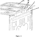
Figure 1 ; is a perspective view of use of the developed flue chamber in a cooking device. -
Figure 2 ; is a side-sectional view of the use of developed flue chamber in a cooking device. -
Figure 3 ; is a perspective view of the use of developed flue chamber with a hearth plate in a cooking device. -
Figure 4 ; is a perspective view of the developed flue chamber. -
Figure 5 ; is an exploded view of the developed flue chamber. - All the parts illustrated in figures are individually assigned a reference numeral and the corresponding terms of these numbers are listed below:
Cooking device (P) Cooking compartment (P1) Flue (P2) Hearth plate (P3) Discharge hole of the hearth plate (P4) Flue chamber (S) Body (1) Opening (1a) Discharge hole (1b) Upper wall (1c) Connection section (1d) Intermediate wall (2) Connection lug (2a) Insulation element (3) Connection element (4) - For the oven-type cooking devices, gases which are formed within the cooking compartment during the cooking process should be discharged. Discharging said gases through a flue directly communicating with the body of the cooking device may cause particularly hearth plate of the cooking device made of inox raw material to get damaged. Therefore, with the present invention, there is developed a flue chamber for use in oven-type cooking devices and providing to discharge, in a reliable manner, gases which are formed within the cooking compartment of the cooking device, and being mounted to the flue outlet.
- The flue chamber (S) according to the present invention, exemplary views of which are provided in
figures 1-4 , is suitable for use in a cooking device (P) which comprises at least one cooking compartment (P1) and at least one flue (P2) communicating with the cooking compartment (P1) on at least one side, the flue chamber comprising at least one body (1) in the form of a hollow box which has at least one opening (1a) on at least one side, and at least one discharge hole (1b) on at least another side; at least one intermediate wall (2) which is positioned in said body (1), partially closes said opening (1a), and forms a discharge line between said discharge hole (1b) and the part of the opening (1a) that is not closed by the intermediate wall; at least one insulation element (3) located between said intermediate wall (2) and the body (1) or between the intermediate wall (2) and the opening (1a), and having heat insulating properties; and at least one connection section (1d) located in said body (1) and connecting the body (1) to the cooking device (P) through the opening. - In an exemplary embodiment of the invention, the intermediate wall (2) positioned within the body (1) partially closes the opening (1a) which is located in the body (1). Here, in the body (1), a discharge line is formed between the discharge hole (1b) and the part of the opening (1a) that is not closed by the intermediate wall (2). At least another side of said flue (P2) which is not communicating with the cooking compartment (P1) is connected to the section of the opening (1a) that is not closed by the intermediate wall (2). In here, gases formed within the cooking compartment (P1) pass, respectively, through the flue (P2), the opening (1a), the discharge line formed within the body (1), and finally the discharge hole (1b) to be sent out. While said gases are discharged in this manner, the insulation element (3) (e.g. a glass wool) located between said intermediate wall (2) and the body (1) or between the intermediate wall (2) and the opening (1a) prevents the heat formed within the discharge line from being transferred to the cooking device (P). In other words, thanks to said insulation element (3), heat exchange between the section of the opening (1a) which is closed by the intermediate wall (2) and the cooking device (P) is blocked. Thus, hearth plate (P3) of the cooking device (P) is prevented to get damaged due to hot gases discharged from the cooking compartment (P1).
- In a preferred embodiment of the invention, said intermediate wall (2) is in the form of a plate which is in connection with an upper wall (1c) of said body (1) on at least one side, and is inclined (in other words, having an acute angle with the upper wall (1c)) so as to approach to said opening (1a) as it moves away from the upper wall (1c). In this embodiment, said insulation element (3) is positioned at the face of the intermediate wall (2), which is in the form of a plate, facing to the opening (1a). In here, when the body (1) is connected to the cooking device (P), said insulation element (3) is between the intermediate wall (2) and the cooking device (P). By this way, a better heat insulation is provided between the cooking device (P) and the discharge line.
- In another preferred embodiment of the present invention, said discharge hole (1b) is positioned at an upper wall (1c) of the body (1). Thus, it is provided to discharge gases, which are coming from the discharge hole, through the discharge hole (1b) in a simpler way. In this embodiment, said discharge hole (1b) is, preferably, aligned coaxially with the discharge hole of the hearth plate (P4).
- Yet in another preferred embodiment of the present invention, said intermediate wall (2) is integral with the body (1). In an alternative embodiment, the intermediate wall (2) is attachable to and detachable from the body (1). In this embodiment, the flue chamber (S) comprises at least one connection lug (2a) located at the intermediate wall (2), and at least one connection element (4), preferably in the form of a screw, to connect said connection lug (2a) to the body (1). Therefore, the flue chamber (S) can be used in a simple and practical manner.
- In another preferred embodiment of the present invention, said flue chamber (S) comprises at least one protective layer (not shown in the figures) located on the body (1) and having high thermal endurance. Said protective layer is preferably in the form of a dye having high temperature endurance. By this way, the body (1) is prevented from being damaged from the hot gas passing through the body (1).
- In the flue chamber (S) according to the present invention, hot air coming from the cooking compartment (P1) of the cooking device (P) via the flue (P2) passes through a discharge line, which is formed by the intermediate wall (2) in the body (1), so as to be sent to the outside through the discharge hole (1b). In here, thanks to the insulation element (3) located between said intermediate wall (2) and the body (1) or between the intermediate wall (2) and the opening (1a), hot air passing through the discharge line is prevented from being transferred to the hearth plate (P3). Therefore, deteriorations are prevented in a practical and reliable manner, which are formed due to the hot gas at the hearth plate (P3) made of inox raw material.
Claims (8)
- A flue chamber (S) suitable for use with a cooking device (P) which comprises at least one cooking compartment (P1) and at least one flue (P2) communicating with the cooking compartment (P1) on at least one side, characterized by comprising- at least one body (1) in the form of a hollow box which has at least one opening (1a) on at least one side, and at least one discharge hole (1b) on at least another side;- at least one intermediate wall (2) which is positioned in said body (1), partially closes said opening (1a), and forms a discharge line between said discharge hole (1b) and the part of the opening (1a) that is not closed by the intermediate wall;- at least one insulation element (3) located between said intermediate wall (2) and the body (1) or between the intermediate wall (2) and the opening (1a), and having heat insulating properties; and- at least one connection section (1d) located in said body (1) and connecting the body (1) to the cooking device (P) through the opening.
- A flue chamber (S) according to claim 1, characterized in that said intermediate wall (2) is in the form of a plate which is in connection with an upper wall (1c) of said body (1) on at least one side, and is inclined so as to approach to said opening (1a) as it moves away from the upper wall (1c).
- A flue chamber (S) according to claim 1, characterized in that said discharge hole (1b) is positioned at an upper wall (1c) of the body (1).
- A flue chamber (S) according to claim 1, characterized in that the intermediate wall (2) is integral with the body (1).
- A flue chamber (S) according to claim 1, characterized in that the intermediate wall (2) is attachable to and detachable from the body (1).
- A flue chamber (S) according to claim 5, characterized by comprising at least one connection lug (2a) located at the intermediate wall (2), and at least one connection element (4) to connect said connection lug (2a) to the body (1).
- A flue chamber (S) according to claim 1, characterized by comprising at least one protective layer located on the body (1) and having high thermal endurance.
- A flue chamber (S) according to claim 1, characterized in that said discharge hole (1b) is aligned coaxially with the discharge hole of the hearth plate (P4).
Applications Claiming Priority (1)
| Application Number | Priority Date | Filing Date | Title |
|---|---|---|---|
| TR2017/21312A TR201721312A2 (en) | 2017-12-22 | 2017-12-22 | A chimney chamber. |
Publications (2)
| Publication Number | Publication Date |
|---|---|
| EP3502570A1 true EP3502570A1 (en) | 2019-06-26 |
| EP3502570B1 EP3502570B1 (en) | 2021-03-31 |
Family
ID=63642710
Family Applications (1)
| Application Number | Title | Priority Date | Filing Date |
|---|---|---|---|
| EP18195164.1A Active EP3502570B1 (en) | 2017-12-22 | 2018-09-18 | A flue chamber |
Country Status (2)
| Country | Link |
|---|---|
| EP (1) | EP3502570B1 (en) |
| TR (1) | TR201721312A2 (en) |
Cited By (1)
| Publication number | Priority date | Publication date | Assignee | Title |
|---|---|---|---|---|
| EP4001776A1 (en) * | 2020-11-17 | 2022-05-25 | Whirlpool Corporation | Cooking appliance having a flue |
Citations (8)
| Publication number | Priority date | Publication date | Assignee | Title |
|---|---|---|---|---|
| US2158881A (en) * | 1935-05-07 | 1939-05-16 | Edison General Elec Appliance | Range |
| US2264657A (en) * | 1937-09-01 | 1941-12-02 | American Stove Co | Range |
| US2274299A (en) * | 1939-09-16 | 1942-02-24 | Tappan Stove Co | Range construction |
| US4021642A (en) * | 1975-02-28 | 1977-05-03 | General Electric Company | Oven exhaust system for range with solid cooktop |
| DE3931482A1 (en) * | 1989-09-21 | 1991-04-04 | Licentia Gmbh | Baking and roasting oven combining microwave and electric cooking - has vent opening incorporating extractor fan and selectively-opened auxiliary vent opening |
| EP2489942A1 (en) * | 2011-02-15 | 2012-08-22 | Vestel Beyaz Esya Sanayi Ve Ticaret A.S. | A cooking device flue system |
| WO2013098251A1 (en) * | 2011-12-30 | 2013-07-04 | Arcelik Anonim Sirketi | An oven comprising an exhaust duct |
| US20160178218A1 (en) * | 2014-12-19 | 2016-06-23 | Miele & Cie. Kg | Kitchen range having a cooking chamber heated by a gas heating source |
-
2017
- 2017-12-22 TR TR2017/21312A patent/TR201721312A2/en unknown
-
2018
- 2018-09-18 EP EP18195164.1A patent/EP3502570B1/en active Active
Patent Citations (8)
| Publication number | Priority date | Publication date | Assignee | Title |
|---|---|---|---|---|
| US2158881A (en) * | 1935-05-07 | 1939-05-16 | Edison General Elec Appliance | Range |
| US2264657A (en) * | 1937-09-01 | 1941-12-02 | American Stove Co | Range |
| US2274299A (en) * | 1939-09-16 | 1942-02-24 | Tappan Stove Co | Range construction |
| US4021642A (en) * | 1975-02-28 | 1977-05-03 | General Electric Company | Oven exhaust system for range with solid cooktop |
| DE3931482A1 (en) * | 1989-09-21 | 1991-04-04 | Licentia Gmbh | Baking and roasting oven combining microwave and electric cooking - has vent opening incorporating extractor fan and selectively-opened auxiliary vent opening |
| EP2489942A1 (en) * | 2011-02-15 | 2012-08-22 | Vestel Beyaz Esya Sanayi Ve Ticaret A.S. | A cooking device flue system |
| WO2013098251A1 (en) * | 2011-12-30 | 2013-07-04 | Arcelik Anonim Sirketi | An oven comprising an exhaust duct |
| US20160178218A1 (en) * | 2014-12-19 | 2016-06-23 | Miele & Cie. Kg | Kitchen range having a cooking chamber heated by a gas heating source |
Cited By (2)
| Publication number | Priority date | Publication date | Assignee | Title |
|---|---|---|---|---|
| EP4001776A1 (en) * | 2020-11-17 | 2022-05-25 | Whirlpool Corporation | Cooking appliance having a flue |
| US11933501B2 (en) | 2020-11-17 | 2024-03-19 | Whirlpool Corporation | Cooking appliance having a flue |
Also Published As
| Publication number | Publication date |
|---|---|
| TR201721312A2 (en) | 2019-07-22 |
| EP3502570B1 (en) | 2021-03-31 |
Similar Documents
| Publication | Publication Date | Title |
|---|---|---|
| US10856692B2 (en) | Thin profile multi-tube burner for gas grill | |
| JP5545422B1 (en) | Heating unit and tunnel oven equipped with it | |
| EP3502570A1 (en) | A flue chamber | |
| US9188343B2 (en) | Oven appliance and a gas burner assembly for the same | |
| US9175859B2 (en) | Burner assembly | |
| CN102379319A (en) | Infrared fuel-gas barbecue oven | |
| US20130220302A1 (en) | Porous insert for a heating element of an oven appliance | |
| US10386075B2 (en) | Cooktop appliance with a gas burner assembly | |
| KR102289739B1 (en) | Door of rice cooker with insulating structure and rice cooker having thereof | |
| US20110186036A1 (en) | Cooking Appliance | |
| CN215127193U (en) | Steaming and baking oven | |
| CN106108688A (en) | Pizza oven | |
| US2102352A (en) | Cooking range with muffle-oven | |
| JPS608561Y2 (en) | plate type cooker | |
| US1262822A (en) | Oven. | |
| KR100741799B1 (en) | Gas copy cooker | |
| US11585601B2 (en) | Flameless impingement oven | |
| JPH035484B2 (en) | ||
| KR200428834Y1 (en) | Portable Gas Oven Range | |
| US1847497A (en) | Water heating apparatus | |
| US1396211A (en) | Gas-burner | |
| KR0121043Y1 (en) | Far Infrared Heater | |
| JP3868465B1 (en) | Cooker | |
| US1456823A (en) | Gas range | |
| US146499A (en) | Improvement in lumber-driers |
Legal Events
| Date | Code | Title | Description |
|---|---|---|---|
| PUAI | Public reference made under article 153(3) epc to a published international application that has entered the european phase |
Free format text: ORIGINAL CODE: 0009012 |
|
| STAA | Information on the status of an ep patent application or granted ep patent |
Free format text: STATUS: THE APPLICATION HAS BEEN PUBLISHED |
|
| AK | Designated contracting states |
Kind code of ref document: A1 Designated state(s): AL AT BE BG CH CY CZ DE DK EE ES FI FR GB GR HR HU IE IS IT LI LT LU LV MC MK MT NL NO PL PT RO RS SE SI SK SM TR |
|
| AX | Request for extension of the european patent |
Extension state: BA ME |
|
| STAA | Information on the status of an ep patent application or granted ep patent |
Free format text: STATUS: REQUEST FOR EXAMINATION WAS MADE |
|
| 17P | Request for examination filed |
Effective date: 20191217 |
|
| RBV | Designated contracting states (corrected) |
Designated state(s): AL AT BE BG CH CY CZ DE DK EE ES FI FR GB GR HR HU IE IS IT LI LT LU LV MC MK MT NL NO PL PT RO RS SE SI SK SM TR |
|
| GRAP | Despatch of communication of intention to grant a patent |
Free format text: ORIGINAL CODE: EPIDOSNIGR1 |
|
| STAA | Information on the status of an ep patent application or granted ep patent |
Free format text: STATUS: GRANT OF PATENT IS INTENDED |
|
| INTG | Intention to grant announced |
Effective date: 20201028 |
|
| GRAJ | Information related to disapproval of communication of intention to grant by the applicant or resumption of examination proceedings by the epo deleted |
Free format text: ORIGINAL CODE: EPIDOSDIGR1 |
|
| STAA | Information on the status of an ep patent application or granted ep patent |
Free format text: STATUS: REQUEST FOR EXAMINATION WAS MADE |
|
| GRAP | Despatch of communication of intention to grant a patent |
Free format text: ORIGINAL CODE: EPIDOSNIGR1 |
|
| STAA | Information on the status of an ep patent application or granted ep patent |
Free format text: STATUS: GRANT OF PATENT IS INTENDED |
|
| GRAS | Grant fee paid |
Free format text: ORIGINAL CODE: EPIDOSNIGR3 |
|
| GRAA | (expected) grant |
Free format text: ORIGINAL CODE: 0009210 |
|
| STAA | Information on the status of an ep patent application or granted ep patent |
Free format text: STATUS: THE PATENT HAS BEEN GRANTED |
|
| INTC | Intention to grant announced (deleted) | ||
| INTG | Intention to grant announced |
Effective date: 20210212 |
|
| AK | Designated contracting states |
Kind code of ref document: B1 Designated state(s): AL AT BE BG CH CY CZ DE DK EE ES FI FR GB GR HR HU IE IS IT LI LT LU LV MC MK MT NL NO PL PT RO RS SE SI SK SM TR |
|
| REG | Reference to a national code |
Ref country code: GB Ref legal event code: FG4D Ref country code: CH Ref legal event code: EP |
|
| REG | Reference to a national code |
Ref country code: DE Ref legal event code: R096 Ref document number: 602018014649 Country of ref document: DE Ref country code: AT Ref legal event code: REF Ref document number: 1377353 Country of ref document: AT Kind code of ref document: T Effective date: 20210415 |
|
| REG | Reference to a national code |
Ref country code: IE Ref legal event code: FG4D |
|
| REG | Reference to a national code |
Ref country code: LT Ref legal event code: MG9D |
|
| PG25 | Lapsed in a contracting state [announced via postgrant information from national office to epo] |
Ref country code: NO Free format text: LAPSE BECAUSE OF FAILURE TO SUBMIT A TRANSLATION OF THE DESCRIPTION OR TO PAY THE FEE WITHIN THE PRESCRIBED TIME-LIMIT Effective date: 20210630 Ref country code: BG Free format text: LAPSE BECAUSE OF FAILURE TO SUBMIT A TRANSLATION OF THE DESCRIPTION OR TO PAY THE FEE WITHIN THE PRESCRIBED TIME-LIMIT Effective date: 20210630 Ref country code: HR Free format text: LAPSE BECAUSE OF FAILURE TO SUBMIT A TRANSLATION OF THE DESCRIPTION OR TO PAY THE FEE WITHIN THE PRESCRIBED TIME-LIMIT Effective date: 20210331 Ref country code: FI Free format text: LAPSE BECAUSE OF FAILURE TO SUBMIT A TRANSLATION OF THE DESCRIPTION OR TO PAY THE FEE WITHIN THE PRESCRIBED TIME-LIMIT Effective date: 20210331 |
|
| PG25 | Lapsed in a contracting state [announced via postgrant information from national office to epo] |
Ref country code: LV Free format text: LAPSE BECAUSE OF FAILURE TO SUBMIT A TRANSLATION OF THE DESCRIPTION OR TO PAY THE FEE WITHIN THE PRESCRIBED TIME-LIMIT Effective date: 20210331 Ref country code: RS Free format text: LAPSE BECAUSE OF FAILURE TO SUBMIT A TRANSLATION OF THE DESCRIPTION OR TO PAY THE FEE WITHIN THE PRESCRIBED TIME-LIMIT Effective date: 20210331 Ref country code: SE Free format text: LAPSE BECAUSE OF FAILURE TO SUBMIT A TRANSLATION OF THE DESCRIPTION OR TO PAY THE FEE WITHIN THE PRESCRIBED TIME-LIMIT Effective date: 20210331 |
|
| REG | Reference to a national code |
Ref country code: NL Ref legal event code: MP Effective date: 20210331 |
|
| REG | Reference to a national code |
Ref country code: AT Ref legal event code: MK05 Ref document number: 1377353 Country of ref document: AT Kind code of ref document: T Effective date: 20210331 |
|
| PG25 | Lapsed in a contracting state [announced via postgrant information from national office to epo] |
Ref country code: LT Free format text: LAPSE BECAUSE OF FAILURE TO SUBMIT A TRANSLATION OF THE DESCRIPTION OR TO PAY THE FEE WITHIN THE PRESCRIBED TIME-LIMIT Effective date: 20210331 Ref country code: EE Free format text: LAPSE BECAUSE OF FAILURE TO SUBMIT A TRANSLATION OF THE DESCRIPTION OR TO PAY THE FEE WITHIN THE PRESCRIBED TIME-LIMIT Effective date: 20210331 Ref country code: CZ Free format text: LAPSE BECAUSE OF FAILURE TO SUBMIT A TRANSLATION OF THE DESCRIPTION OR TO PAY THE FEE WITHIN THE PRESCRIBED TIME-LIMIT Effective date: 20210331 Ref country code: AT Free format text: LAPSE BECAUSE OF FAILURE TO SUBMIT A TRANSLATION OF THE DESCRIPTION OR TO PAY THE FEE WITHIN THE PRESCRIBED TIME-LIMIT Effective date: 20210331 Ref country code: NL Free format text: LAPSE BECAUSE OF FAILURE TO SUBMIT A TRANSLATION OF THE DESCRIPTION OR TO PAY THE FEE WITHIN THE PRESCRIBED TIME-LIMIT Effective date: 20210331 Ref country code: SM Free format text: LAPSE BECAUSE OF FAILURE TO SUBMIT A TRANSLATION OF THE DESCRIPTION OR TO PAY THE FEE WITHIN THE PRESCRIBED TIME-LIMIT Effective date: 20210331 |
|
| PG25 | Lapsed in a contracting state [announced via postgrant information from national office to epo] |
Ref country code: IS Free format text: LAPSE BECAUSE OF FAILURE TO SUBMIT A TRANSLATION OF THE DESCRIPTION OR TO PAY THE FEE WITHIN THE PRESCRIBED TIME-LIMIT Effective date: 20210731 Ref country code: PT Free format text: LAPSE BECAUSE OF FAILURE TO SUBMIT A TRANSLATION OF THE DESCRIPTION OR TO PAY THE FEE WITHIN THE PRESCRIBED TIME-LIMIT Effective date: 20210802 Ref country code: PL Free format text: LAPSE BECAUSE OF FAILURE TO SUBMIT A TRANSLATION OF THE DESCRIPTION OR TO PAY THE FEE WITHIN THE PRESCRIBED TIME-LIMIT Effective date: 20210331 Ref country code: RO Free format text: LAPSE BECAUSE OF FAILURE TO SUBMIT A TRANSLATION OF THE DESCRIPTION OR TO PAY THE FEE WITHIN THE PRESCRIBED TIME-LIMIT Effective date: 20210331 Ref country code: SK Free format text: LAPSE BECAUSE OF FAILURE TO SUBMIT A TRANSLATION OF THE DESCRIPTION OR TO PAY THE FEE WITHIN THE PRESCRIBED TIME-LIMIT Effective date: 20210331 |
|
| REG | Reference to a national code |
Ref country code: DE Ref legal event code: R097 Ref document number: 602018014649 Country of ref document: DE |
|
| PG25 | Lapsed in a contracting state [announced via postgrant information from national office to epo] |
Ref country code: ES Free format text: LAPSE BECAUSE OF FAILURE TO SUBMIT A TRANSLATION OF THE DESCRIPTION OR TO PAY THE FEE WITHIN THE PRESCRIBED TIME-LIMIT Effective date: 20210331 Ref country code: AL Free format text: LAPSE BECAUSE OF FAILURE TO SUBMIT A TRANSLATION OF THE DESCRIPTION OR TO PAY THE FEE WITHIN THE PRESCRIBED TIME-LIMIT Effective date: 20210331 Ref country code: DK Free format text: LAPSE BECAUSE OF FAILURE TO SUBMIT A TRANSLATION OF THE DESCRIPTION OR TO PAY THE FEE WITHIN THE PRESCRIBED TIME-LIMIT Effective date: 20210331 |
|
| PLBE | No opposition filed within time limit |
Free format text: ORIGINAL CODE: 0009261 |
|
| STAA | Information on the status of an ep patent application or granted ep patent |
Free format text: STATUS: NO OPPOSITION FILED WITHIN TIME LIMIT |
|
| 26N | No opposition filed |
Effective date: 20220104 |
|
| REG | Reference to a national code |
Ref country code: DE Ref legal event code: R119 Ref document number: 602018014649 Country of ref document: DE |
|
| REG | Reference to a national code |
Ref country code: CH Ref legal event code: PL |
|
| REG | Reference to a national code |
Ref country code: BE Ref legal event code: MM Effective date: 20210930 |
|
| PG25 | Lapsed in a contracting state [announced via postgrant information from national office to epo] |
Ref country code: IS Free format text: LAPSE BECAUSE OF FAILURE TO SUBMIT A TRANSLATION OF THE DESCRIPTION OR TO PAY THE FEE WITHIN THE PRESCRIBED TIME-LIMIT Effective date: 20210731 Ref country code: MC Free format text: LAPSE BECAUSE OF FAILURE TO SUBMIT A TRANSLATION OF THE DESCRIPTION OR TO PAY THE FEE WITHIN THE PRESCRIBED TIME-LIMIT Effective date: 20210331 |
|
| PG25 | Lapsed in a contracting state [announced via postgrant information from national office to epo] |
Ref country code: LU Free format text: LAPSE BECAUSE OF NON-PAYMENT OF DUE FEES Effective date: 20210918 Ref country code: IE Free format text: LAPSE BECAUSE OF NON-PAYMENT OF DUE FEES Effective date: 20210918 Ref country code: DE Free format text: LAPSE BECAUSE OF NON-PAYMENT OF DUE FEES Effective date: 20220401 Ref country code: BE Free format text: LAPSE BECAUSE OF NON-PAYMENT OF DUE FEES Effective date: 20210930 |
|
| PG25 | Lapsed in a contracting state [announced via postgrant information from national office to epo] |
Ref country code: LI Free format text: LAPSE BECAUSE OF NON-PAYMENT OF DUE FEES Effective date: 20210930 Ref country code: CH Free format text: LAPSE BECAUSE OF NON-PAYMENT OF DUE FEES Effective date: 20210930 |
|
| PGFP | Annual fee paid to national office [announced via postgrant information from national office to epo] |
Ref country code: GB Payment date: 20220920 Year of fee payment: 5 |
|
| PGFP | Annual fee paid to national office [announced via postgrant information from national office to epo] |
Ref country code: FR Payment date: 20220921 Year of fee payment: 5 |
|
| PG25 | Lapsed in a contracting state [announced via postgrant information from national office to epo] |
Ref country code: CY Free format text: LAPSE BECAUSE OF FAILURE TO SUBMIT A TRANSLATION OF THE DESCRIPTION OR TO PAY THE FEE WITHIN THE PRESCRIBED TIME-LIMIT Effective date: 20210331 |
|
| PG25 | Lapsed in a contracting state [announced via postgrant information from national office to epo] |
Ref country code: HU Free format text: LAPSE BECAUSE OF FAILURE TO SUBMIT A TRANSLATION OF THE DESCRIPTION OR TO PAY THE FEE WITHIN THE PRESCRIBED TIME-LIMIT; INVALID AB INITIO Effective date: 20180918 Ref country code: GR Free format text: LAPSE BECAUSE OF FAILURE TO SUBMIT A TRANSLATION OF THE DESCRIPTION OR TO PAY THE FEE WITHIN THE PRESCRIBED TIME-LIMIT Effective date: 20210331 |
|
| PG25 | Lapsed in a contracting state [announced via postgrant information from national office to epo] |
Ref country code: MK Free format text: LAPSE BECAUSE OF FAILURE TO SUBMIT A TRANSLATION OF THE DESCRIPTION OR TO PAY THE FEE WITHIN THE PRESCRIBED TIME-LIMIT Effective date: 20210331 |
|
| GBPC | Gb: european patent ceased through non-payment of renewal fee |
Effective date: 20230918 |
|
| PG25 | Lapsed in a contracting state [announced via postgrant information from national office to epo] |
Ref country code: GB Free format text: LAPSE BECAUSE OF NON-PAYMENT OF DUE FEES Effective date: 20230918 |
|
| PG25 | Lapsed in a contracting state [announced via postgrant information from national office to epo] |
Ref country code: GB Free format text: LAPSE BECAUSE OF NON-PAYMENT OF DUE FEES Effective date: 20230918 Ref country code: FR Free format text: LAPSE BECAUSE OF NON-PAYMENT OF DUE FEES Effective date: 20230930 |
|
| PG25 | Lapsed in a contracting state [announced via postgrant information from national office to epo] |
Ref country code: MT Free format text: LAPSE BECAUSE OF FAILURE TO SUBMIT A TRANSLATION OF THE DESCRIPTION OR TO PAY THE FEE WITHIN THE PRESCRIBED TIME-LIMIT Effective date: 20210331 |
|
| PGFP | Annual fee paid to national office [announced via postgrant information from national office to epo] |
Ref country code: TR Payment date: 20250917 Year of fee payment: 8 Ref country code: IT Payment date: 20250923 Year of fee payment: 8 |