EP3502495A1 - Connecting rod manufacturing method and connecting rod - Google Patents
Connecting rod manufacturing method and connecting rod Download PDFInfo
- Publication number
- EP3502495A1 EP3502495A1 EP18206843.7A EP18206843A EP3502495A1 EP 3502495 A1 EP3502495 A1 EP 3502495A1 EP 18206843 A EP18206843 A EP 18206843A EP 3502495 A1 EP3502495 A1 EP 3502495A1
- Authority
- EP
- European Patent Office
- Prior art keywords
- holes
- hole
- fracture
- connecting rod
- circumferential surface
- Prior art date
- Legal status (The legal status is an assumption and is not a legal conclusion. Google has not performed a legal analysis and makes no representation as to the accuracy of the status listed.)
- Granted
Links
Images






Classifications
-
- B—PERFORMING OPERATIONS; TRANSPORTING
- B23—MACHINE TOOLS; METAL-WORKING NOT OTHERWISE PROVIDED FOR
- B23K—SOLDERING OR UNSOLDERING; WELDING; CLADDING OR PLATING BY SOLDERING OR WELDING; CUTTING BY APPLYING HEAT LOCALLY, e.g. FLAME CUTTING; WORKING BY LASER BEAM
- B23K26/00—Working by laser beam, e.g. welding, cutting or boring
- B23K26/36—Removing material
- B23K26/38—Removing material by boring or cutting
-
- F—MECHANICAL ENGINEERING; LIGHTING; HEATING; WEAPONS; BLASTING
- F16—ENGINEERING ELEMENTS AND UNITS; GENERAL MEASURES FOR PRODUCING AND MAINTAINING EFFECTIVE FUNCTIONING OF MACHINES OR INSTALLATIONS; THERMAL INSULATION IN GENERAL
- F16C—SHAFTS; FLEXIBLE SHAFTS; ELEMENTS OR CRANKSHAFT MECHANISMS; ROTARY BODIES OTHER THAN GEARING ELEMENTS; BEARINGS
- F16C9/00—Bearings for crankshafts or connecting-rods; Attachment of connecting-rods
- F16C9/04—Connecting-rod bearings; Attachments thereof
- F16C9/045—Connecting-rod bearings; Attachments thereof the bearing cap of the connecting rod being split by fracturing
-
- B—PERFORMING OPERATIONS; TRANSPORTING
- B21—MECHANICAL METAL-WORKING WITHOUT ESSENTIALLY REMOVING MATERIAL; PUNCHING METAL
- B21D—WORKING OR PROCESSING OF SHEET METAL OR METAL TUBES, RODS OR PROFILES WITHOUT ESSENTIALLY REMOVING MATERIAL; PUNCHING METAL
- B21D53/00—Making other particular articles
- B21D53/84—Making other particular articles other parts for engines, e.g. connecting-rods
-
- B—PERFORMING OPERATIONS; TRANSPORTING
- B23—MACHINE TOOLS; METAL-WORKING NOT OTHERWISE PROVIDED FOR
- B23D—PLANING; SLOTTING; SHEARING; BROACHING; SAWING; FILING; SCRAPING; LIKE OPERATIONS FOR WORKING METAL BY REMOVING MATERIAL, NOT OTHERWISE PROVIDED FOR
- B23D31/00—Shearing machines or shearing devices covered by none or more than one of the groups B23D15/00 - B23D29/00; Combinations of shearing machines
- B23D31/002—Breaking machines, i.e. pre-cutting and subsequent breaking
-
- B—PERFORMING OPERATIONS; TRANSPORTING
- B23—MACHINE TOOLS; METAL-WORKING NOT OTHERWISE PROVIDED FOR
- B23K—SOLDERING OR UNSOLDERING; WELDING; CLADDING OR PLATING BY SOLDERING OR WELDING; CUTTING BY APPLYING HEAT LOCALLY, e.g. FLAME CUTTING; WORKING BY LASER BEAM
- B23K26/00—Working by laser beam, e.g. welding, cutting or boring
- B23K26/36—Removing material
- B23K26/38—Removing material by boring or cutting
- B23K26/382—Removing material by boring or cutting by boring
-
- F—MECHANICAL ENGINEERING; LIGHTING; HEATING; WEAPONS; BLASTING
- F16—ENGINEERING ELEMENTS AND UNITS; GENERAL MEASURES FOR PRODUCING AND MAINTAINING EFFECTIVE FUNCTIONING OF MACHINES OR INSTALLATIONS; THERMAL INSULATION IN GENERAL
- F16C—SHAFTS; FLEXIBLE SHAFTS; ELEMENTS OR CRANKSHAFT MECHANISMS; ROTARY BODIES OTHER THAN GEARING ELEMENTS; BEARINGS
- F16C7/00—Connecting-rods or like links pivoted at both ends; Construction of connecting-rod heads
- F16C7/02—Constructions of connecting-rods with constant length
-
- F—MECHANICAL ENGINEERING; LIGHTING; HEATING; WEAPONS; BLASTING
- F16—ENGINEERING ELEMENTS AND UNITS; GENERAL MEASURES FOR PRODUCING AND MAINTAINING EFFECTIVE FUNCTIONING OF MACHINES OR INSTALLATIONS; THERMAL INSULATION IN GENERAL
- F16C—SHAFTS; FLEXIBLE SHAFTS; ELEMENTS OR CRANKSHAFT MECHANISMS; ROTARY BODIES OTHER THAN GEARING ELEMENTS; BEARINGS
- F16C7/00—Connecting-rods or like links pivoted at both ends; Construction of connecting-rod heads
- F16C7/02—Constructions of connecting-rods with constant length
- F16C7/023—Constructions of connecting-rods with constant length for piston engines, pumps or the like
-
- F—MECHANICAL ENGINEERING; LIGHTING; HEATING; WEAPONS; BLASTING
- F16—ENGINEERING ELEMENTS AND UNITS; GENERAL MEASURES FOR PRODUCING AND MAINTAINING EFFECTIVE FUNCTIONING OF MACHINES OR INSTALLATIONS; THERMAL INSULATION IN GENERAL
- F16C—SHAFTS; FLEXIBLE SHAFTS; ELEMENTS OR CRANKSHAFT MECHANISMS; ROTARY BODIES OTHER THAN GEARING ELEMENTS; BEARINGS
- F16C2220/00—Shaping
- F16C2220/80—Shaping by separating parts, e.g. by severing, cracking
-
- F—MECHANICAL ENGINEERING; LIGHTING; HEATING; WEAPONS; BLASTING
- F16—ENGINEERING ELEMENTS AND UNITS; GENERAL MEASURES FOR PRODUCING AND MAINTAINING EFFECTIVE FUNCTIONING OF MACHINES OR INSTALLATIONS; THERMAL INSULATION IN GENERAL
- F16C—SHAFTS; FLEXIBLE SHAFTS; ELEMENTS OR CRANKSHAFT MECHANISMS; ROTARY BODIES OTHER THAN GEARING ELEMENTS; BEARINGS
- F16C2240/00—Specified values or numerical ranges of parameters; Relations between them
- F16C2240/30—Angles, e.g. inclinations
-
- F—MECHANICAL ENGINEERING; LIGHTING; HEATING; WEAPONS; BLASTING
- F16—ENGINEERING ELEMENTS AND UNITS; GENERAL MEASURES FOR PRODUCING AND MAINTAINING EFFECTIVE FUNCTIONING OF MACHINES OR INSTALLATIONS; THERMAL INSULATION IN GENERAL
- F16C—SHAFTS; FLEXIBLE SHAFTS; ELEMENTS OR CRANKSHAFT MECHANISMS; ROTARY BODIES OTHER THAN GEARING ELEMENTS; BEARINGS
- F16C2240/00—Specified values or numerical ranges of parameters; Relations between them
- F16C2240/40—Linear dimensions, e.g. length, radius, thickness, gap
- F16C2240/44—Hole or pocket sizes
-
- F—MECHANICAL ENGINEERING; LIGHTING; HEATING; WEAPONS; BLASTING
- F16—ENGINEERING ELEMENTS AND UNITS; GENERAL MEASURES FOR PRODUCING AND MAINTAINING EFFECTIVE FUNCTIONING OF MACHINES OR INSTALLATIONS; THERMAL INSULATION IN GENERAL
- F16C—SHAFTS; FLEXIBLE SHAFTS; ELEMENTS OR CRANKSHAFT MECHANISMS; ROTARY BODIES OTHER THAN GEARING ELEMENTS; BEARINGS
- F16C2360/00—Engines or pumps
- F16C2360/22—Internal combustion engines
Definitions
- the present invention relates to a connecting rod manufacturing method and a connecting rod.
- a connecting rod manufacturing method involves forming, in an inner circumferential surface of a through-hole formed at an end of the connecting rod, a plurality of holes so as to extend in the same direction along an axial direction of the through-hole, and then fracture-splitting the end into a rod part and a cap part using these holes as a fracture start portion (e.g., see International Publication No. WO 2004/007980 ).
- the rod part and the cap part after fracture are assembled with the fracture surfaces positioned relative to each other. It is therefore desirable that the rod part and the cap part be fractured by brittle fracture and that the surface properties of the fracture surfaces be secured.
- a location at which an initial crack occurs upon fracture may vary due to variations in shape and position of the holes etc.
- ductile fracture may occur at portions of the rod part and the cap part, which would degrade the surface properties of the fracture surfaces and reduce the positioning accuracy of the fracture surfaces.
- the present invention provides a connecting rod manufacturing method and a connecting rod that allow the surface properties of the fracture surfaces of the rod part and the cap part to be secured.
- a first aspect of the present invention relates to a connecting rod manufacturing method including: forming, in an inner circumferential surface of a through-hole formed at an end of the connecting rod, a plurality of first holes as fracture start portions such that the first holes are arrayed in an axial direction of the through-hole and extend in a first direction,; forming a plurality of second holes as the fracture start portions, each between adjacent ones of the first holes, such that the second holes are arrayed in the axial direction and extend in a second direction different from the first direction relative to the first holes; and fracture-splitting the end of the connecting rod into the rod part and the cap part using the fracture start portions as start points.
- first holes and the second holes extend in different directions and the second holes are each formed between adjacent ones of the first holes, each region surrounded by the inner circumferential surface of the through-hole and the first and second holes that are adjacent to each other constitutes a region that contributes little to fracture strength. Accordingly, the fracture strength at the fracture start portions can be reduced compared with when merely a plurality of holes extending in the same direction is formed as fracture start portions. Therefore, an even initial crack is formed upon fracture, as this initial crack occurs so as to provide communication between the first holes and the second holes arrayed in the axial direction of the connecting rod. With the initial crack thus evenly formed, variations in subsequent propagation of the crack are reduced and brittle fracture can be secured. Thus, the surface properties of the fracture surfaces of the rod part and the cap part can be secured.
- the first hole and the second hole that are adjacent to each other may partially communicate with each other.
- the first hole and the second hole that are adjacent to each other may communicate with each other at ends opening in the inner circumferential surface.
- the first hole may communicate with one second hole, located at one end of three second holes that are adjacent to one another, at ends opening in the inner circumferential surface, communicate with another second hole, located at the other end of the three second holes, at leading ends, and communicate with the other second hole, located between the one end and the other end of the three second holes, at intermediate portions.
- the first hole may communicate with one of two second holes that are adjacent to each other at ends opening in the inner circumferential surface, and communicate with the other one of the two second holes at leading ends.
- the two second holes may extend in a direction orthogonal to the inner circumferential surface of the through-hole.
- the second hole may communicate with one of two first holes that are adjacent to each other at intermediate portions, and communicate with the other one of the two first holes at intermediate portions.
- the second hole may be shorter than the first hole.
- the connecting rod manufacturing method may further include cooling the fracture start portions between forming the first holes and forming the second holes.
- the fracture start portions may include a first fracture start portion and a second fracture start portion facing each other across the center of the through-hole.
- the first holes or the second holes may be formed as the second fracture start portion by laser beam machining, while cooling of the first fracture start portion is in progress after the first holes are formed as the first fracture start portion by laser beam machining and before the second holes are formed as the first fracture start portion.
- a relationship between an inside diameter d of each of the first hole and the second hole of which leading ends are adjacent to each other and a distance A in the axial direction between the leading ends may satisfy - (d / 4) ⁇ A ⁇ d.
- a relative angle ⁇ between axes of the first hole and the second hole may satisfy 30° ⁇ ⁇ ⁇ 150°.
- a second aspect of the present invention relates to a connecting rod including: a rod part having a fracture surface; and a cap part that has a fracture surface, and defines a through-hole together with the rod part in a state where the fracture surfaces are positioned relative to each other.
- a plurality of first holes that is arrayed in an axial direction of the through-hole and extends in a first direction from an inner circumferential surface of the through-hole, and a plurality of second holes that is arrayed in the axial direction and extends from the inner circumferential surface in a second direction different from the first direction relative to the first holes, are present between the fracture surfaces.
- the present invention can provide a connecting rod manufacturing method and a connecting rod that allow the surface properties of the fracture surfaces of the rod part and the cap part to be secured.
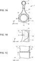
- FIG. 1A is a view illustrating a base member 1 of a connecting rod of an internal combustion engine.
- the base member 1 is a steel member formed by casting or forging.
- the base member 1 has a through-hole 12 formed at a small end 11 located on one end side in a Y-direction that is a long-side direction, and has a through-hole 14 formed at a big end 13 located on the other end side in the Y-direction.
- the connecting rod is installed in the internal combustion engine, with a piston pin and a crank pin inserted into the through-hole 12 and the through-hole 14, respectively.
- the base member 1 has a rod part 20 and a cap part 30 that are continuous with each other in the Y-direction.
- the small end 11, the through-hole 12, and a half of the circle of the through-hole 14 are formed.
- the cap part 30, the other half of the circle of the through-hole 14 is formed.
- the rod part 20 and the cap part 30 are intended to be fracture-split using fracture start portions 50, 60 formed in an inner circumferential surface of the through-hole 14 as start points.
- the fracture start portions 50, 60 are formed at positions respectively on both sides of the through-hole 14 in an X-direction that is a short-side direction.
- the rod part 20 and the cap part 30 are fracture-split from the fracture start portions 50, 60 as start points, as a predetermined jig is inserted into the through-hole 14 and a tensile load is applied so as to separate the rod part 20 and the cap part 30 from each other in the Y-direction.
- a pair of split pieces is set inside the through-hole 14 side by side in the Y-direction, and a tapered member is inserted between these split pieces. Then, impact is exerted from above on the tapered member such that the tapered member separates the pair of split pieces from each other in the Y-direction.
- the rod part 20 and the cap part 30 have bolt holes 15, 16 into which bolts for connecting the rod part 20 and the cap part 30 to each other after fracture splitting are inserted.
- the bolt holes 15, 16 are also formed at positions respectively on both sides of the through-hole 14 in the X-direction.
- FIG. 1B is a partially enlarged view of FIG. 1A
- FIG. 1C is a view along arrow C in FIG. 1B
- the fracture start portion 50 is composed of a plurality of holes formed so as to be arrayed in a Z-direction that is a thickness direction of the base member 1 as well as an axial direction of the through-hole 14. These holes are formed such that axes thereof are included in a plane orthogonal to the Y-direction.
- the same description applies to the fracture start portion 60.
- the fracture start portions 50, 60 are examples of the first and second fracture start portions.
- FIG. 2A is a view of section I-I in FIG. 1C .
- the fracture start portion 50 is composed of pluralities of holes 51, 55.
- the holes 51, 55 extend in different directions from the inner circumferential surface of the through-hole 14.
- the holes 51 extend parallel to one another and the holes 55 extend parallel to one another.
- the holes 51, 55 are formed by laser beam machining. The same description applies to the fracture start portion 60.
- the holes 51, 55 are examples of the first and second holes.
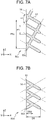
- FIG. 2B is a partially enlarged view of FIG. 2A . Hatching is omitted in FIG. 2B .
- the holes 51, 55 are formed in an X-shape as seen in a sectional view, and the holes 51, 55 communicate with each other at leading ends. Inside diameters d of the holes 51, 55 are set to be approximately equal. As will be described later in detail, a depth D1 and a depth D5 in the X-direction of the hole 51 and the hole 55, respectively, are set to be approximately equal. As will be described later in detail, a pitch P1 in the Z-direction of the adjacent holes 51 and a pitch P5 in the Z-direction of the adjacent holes 55 are set to be approximately equal within a predetermined range.
- a relative angle ⁇ between the axes of the holes 51, 55 is set to be within a predetermined angle range.
- a distance A in the Z-direction between leading ends of the holes 51, 55 of which the leading ends are adjacent to each other is set to be within a predetermined range.
- the hole 51 communicates with one hole 55, located at one end of three holes 55 that are adjacent to one another, at ends opening in the inner circumferential surface of the through-hole 14, communicates with another hole 55, located at the other end of the three holes 55, at leading ends, and communicates with the other hole 55, located between the one end and the other end of the three holes 55, at intermediate portions. This means that one hole 51 communicates with three holes 55.
- the hole 55 communicates with one hole 51, located at one end of three holes 51 that are adjacent to one another, at the ends opening in the inner circumferential surface of the through-hole 14, communicates with another hole 51, located at the other end of the three holes 51, at the leading ends, and communicates with the other hole 51, located between the one end and the other end of the three holes 51, at intermediate portions.
- one hole 55 communicates with three holes 51.
- the holes 51, 55 communicate with each other at many portions.
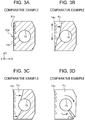
- FIG. 3A to FIG. 3D are views illustrating propagation of a crack upon fracture in the comparative example.
- a fracture start portion 50v that is the comparative example is composed only of a plurality of holes 51v extending in the same direction.
- the depth of the hole 51v is relatively small and the radius of curvature of a leading end thereof is relatively large.
- the holes 51v vary widely in pitch and depth. As shown in FIG. 3B to FIG.
- a crack upon fracture, a crack propagates from the fracture start portion 50v as a start point, from an inner circumferential surface side toward an outer circumferential surface side of a through-hole 14v.
- the locations at which the initial crack occurs upon fracture is likely to vary in the Z-direction as shown in FIG. 3B .
- the propagation of the crack in the X-direction also varies among positions in the Z-direction as shown in FIG. 3C , so that the location at which portions of the crack join each other after propagating around the bolt hole 15 also varies as shown in FIG. 3D .
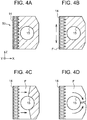
- FIG. 4A to FIG. 4D are views illustrating propagation of a crack upon fracture in the embodiment.
- an initial crack occurs roughly at the same time, without variations among positions in the Z-direction.
- the holes 51 and the holes 55 extend in different directions and the holes 55 are each formed between adjacent ones of the holes 51.
- each region surrounded by the inner circumferential surface of the through-hole 14 and the holes 51, 55 that are adjacent to each other constitutes a region that contributes little to the fracture strength. Accordingly, the fracture strength is reduced when such holes 51, 55 are formed, compared with when merely a plurality of holes extending in the same direction at a constant pitch is formed as a fracture start portion.
- an even initial crack is formed upon fracture, as this initial crack occurs so as to provide communication between the holes 51, 55 arrayed in the Z-direction.
- stress concentrated at the leading end of the hole 51 affects the leading end of the adjacent hole 55
- stress concentrated at the leading end of the hole 55 affects the leading end of the adjacent hole 51, which seems to facilitate the occurrence of a crack so as to provide communication between the holes 51, 55 arrayed in the Z-direction.
- variations in propagation of the crack in the X-direction among positions in the Z-direction are suppressed as shown in FIG. 4C , and portions of the crack join each other after propagating around the bolt hole 15 as shown in FIG. 4D .
- the distance between the leading ends, the relative angle, etc. of the holes 51, 55 in the embodiment are set to be within predetermined ranges. This will be described later in detail.
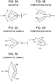
- FIG. 5A is an enlarged view of the leading ends of the holes 51, 55 of the embodiment. Hatching is omitted in FIG. 5A to facilitate understanding.
- the distance A between the leading ends of the holes 51, 55 is set to approximately zero, and the relative angle ⁇ between the axes of the holes 51, 55 is set to approximately 60°. Since the distance A is set to zero, the holes 51, 55 communicate with each other at the adjoining leading ends.
- FIG. 5B is an enlarged view of leading ends of a hole 51w and a hole 55w of a comparative example. Reference signs similar to those of the embodiment will be used in the comparative examples to omit an overlapping description.
- the following description assumes that the inside diameters of the holes of the comparative examples are d and equal to the inside diameters of the holes 51, 55.
- a distance Aw between the leading ends of the holes 51w, 55w is set to be larger than the inside diameter d. This may make it difficult to cause interference between stress concentrated upon fracture at the leading end of the hole 51w and that at the leading end of the hole 55w. Accordingly, the location at which the initial crack occurs upon fracture may be more likely to vary among positions in the Z-direction.
- the distance A satisfy A ⁇ d. Since the distance A between the holes 51, 55 of the embodiment is set to approximately zero, it is easy to cause interference between stress concentrated upon fracture at the leading end of the hole 51 and that at the leading end of the hole 55. Thus, an even initial crack is formed as this initial crack occurs so as to provide communication between the holes 51, 55 arrayed in the Z-direction.
- FIG. 5C is an enlarged view of holes 51x, 55x of a comparative example.
- a distance Ax between leading ends of the holes 51x, 55x is set to a value smaller than - (d / 4).
- the holes 51x, 55x are formed so as to have a large amount of overlap at the leading ends.
- these holes are formed by laser beam machining as described above.
- a large amount of overlap between leading ends as with the holes 51x, 55x means that a large amount of heat has been applied by laser irradiation to the leading ends of the holes 51x, 55x located at the same position, which may make the radii of curvature of the leading ends too large.
- the distance A satisfy - (d / 4) ⁇ A. Since the distance A between the holes 51, 55 of the embodiment is set to zero as described above, making the radii of curvature of the leading ends too large is avoided, so that the factor of stress concentration is secured and brittle fracture is secured.
- FIG. 5D is an enlarged view of holes 51y, 55y of a comparative example.
- a relative angle ⁇ y between axes of the holes 51y, 55y is set to be smaller than 30°. This case also means that the amount of overlap between the leading ends of the holes 51y, 55y is large, and that a larger amount of heat has been applied by laser irradiation to a region where the holes 51y, 55y overlap each other. Accordingly, also in this case, the radii of curvature of the leading ends may be too large, and ductile fracture may be more likely to occur. It is therefore preferable that the relative angle ⁇ satisfy 30° ⁇ ⁇ . Since the relative angle ⁇ between the holes 51, 55 of the embodiment is set to approximately 60°, making the radii of curvature of the leading ends too large is avoided.
- FIG. 5E is an enlarged view of holes 51z, 55z of a comparative example.
- a relative angle ⁇ z between axes of the holes 51z, 55z is set to be larger than 150°.
- a laser beam is required to be applied to the inner circumferential surface of the through-hole 14 at too steep an angle, making it difficult to form the holes 51z, 55z as well as to secure the depth of the holes 51z, 55z.
- the relative angle ⁇ satisfy ⁇ ⁇ 150°. Since the relative angle ⁇ between the holes 51, 55 of the embodiment is set to substantially 60°, it is easy to form the holes 51, 55 as well as to secure the depth of the holes 51, 55.
- the distance A satisfy - (d / 4) ⁇ A ⁇ d and that the relative angle ⁇ satisfy 30° ⁇ ⁇ ⁇ 150°. It is more preferable that the distance A satisfy - (d / 8) ⁇ A ⁇ d / 2 and that the relative angle ⁇ satisfy 15° ⁇ ⁇ ⁇ 75°.
- each of the pitches PI, P5 be about twice the inside diameter d of the hole.
- the pitch is too narrow, a large number of holes are required to be formed in a narrow region by laser beam machining.
- the temperature of the base member 1 rises, which may affect the dimensional accuracy of the holes during laser beam machining.
- the manufacturing cost may increase due to the increased number of times of laser irradiation.
- the holes 51, 55 that are adjacent to each other communicate with each other at the open ends opening in the inner circumferential surface of the through-hole 14. This is because the fracture strength on the inner circumferential surface side of the through-hole 14 can be reduced and brittle fracture can be thereby secured when the open ends communicate with each other, compared with when the open ends are separated from each other without communicating with each other.
- the holes 51, 55 before fracture are exposed in the form of grooves.
- the same holes 51, 55 as in the state before fracture are defined again between the fracture surfaces.
- the same description applies to the fracture start portion 60.
- a connecting rod that has been manufactured by fastening together the rod part 20 and the cap part 30 after fracture can be checked as to whether the holes 51, 55 of the fracture start portion 50 satisfy the above requirements.
- FIG. 6A to FIG. 7B are enlarged views of holes that are the modified examples.
- the same components as in the embodiment will be denoted by the same reference signs to omit an overlapping description.
- Holes 51a, 55a of a fracture start portion 50a shown in FIG. 6A are formed in a V-shape as seen in a sectional view.
- the holes 51a, 55a do not communicate with each other at intermediate portions, and a relative angle ⁇ a therebetween is set to approximately 30°.
- the hole 51a communicates with one of two holes 55a that are adjacent to each other at ends opening in the inner circumferential surface of the through-hole 14, and communicates with the other one of the two holes 55a at leading ends.
- the hole 55a communicates with one of two holes 51a that are adjacent to each other at the ends opening in the inner circumferential surface of the through-hole 14, and communicates with the other one of the two holes 51a at the leading ends.
- the fracture strength can be reduced in each region surrounded by the holes 51a, 55a that are adjacent to each other and the inner circumferential surface of the through-hole 14, and brittle fracture can be thereby secured.
- Holes 51, 55b of a fracture start portion 50b shown in FIG. 6B are formed in a V-shape as seen in a sectional view.
- the holes 55b extend substantially parallel to the X-direction.
- the holes 55b extend in a radial direction of the through-hole 14.
- the holes may extend in a direction orthogonal to the inner circumferential surface of the through-hole 14.
- a relative angle ⁇ b between axes of the holes 51, 55b is set to approximately 30°.
- a pitch P5c of holes 55c of a fracture start portion 50c shown in FIG. 7A is set to be approximately three times the pitch P1 of the holes 51, and thus the pitch ratio is set to 1:3.
- a smaller number of the holes 55c are required relative to the holes 51, so that the number of times of laser irradiation for forming the holes 55c can be reduced and the manufacturing process can be simplified.
- the hole 55c communicates with four holes 51, the fracture strength can be reduced and brittle fracture can be thereby secured.
- regions surrounded by the hole 55c, the four holes 51 communicating with this hole 55c, and the inner circumferential surface of the through-hole 14 are secured, so that the fracture strength can be reduced and brittle fracture can be thereby secured.
- the relative angle between these holes may be so large as to make it difficult to apply a laser beam to the inner circumferential surface of the through-hole 14. It is therefore preferable that the pitch ratio be between 1:1 and 1:3.
- a relative angle ⁇ c between axes of the holes 51, 55c is set to approximately 90°. In this modified example, it is not absolutely necessary that the hole 55c communicates with four holes 51, as long as the hole 55c communicates with one of two holes 51 that are adjacent to each other at intermediate portions, and communicates with the other one of these two holes 51 at intermediate portions.
- a depth D5d of a hole 55d shown in FIG. 7B is set to half the depth D1 of the hole 51, and thus the ratio between the depths of the holes is set to 1:0.5.
- the hole 55d is formed to be shorter than the hole 51.
- regions between the holes 51, 55d and the inner circumferential surface of the through-hole 14 are secured, so that the fracture strength can be reduced and brittle fracture can be thereby secured.
- the hole 55d communicates with the hole 51 at an intermediate portion of the hole 51, the fracture strength can be further reduced and brittle fracture can be thereby secured.
- the depth of the hole 55d is smaller than the depth of the hole 51, the hole 55d can be formed by laser beam machining at lower laser output power and in a shorter time, which can reduce the manufacturing cost.
- the present invention is not limited to this arrangement and the open ends may be separated as shown in FIG. 7A .
- FIG. 8 is a flowchart showing the process of forming the fracture start portions 50, 60.
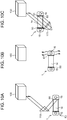
- FIG. 9A to FIG. 10C are views illustrating the process of forming the fracture start portions 50, 60.
- the holes 51 are formed by applying a laser beam from a laser oscillator 100 to a part of the inner circumferential surface of the through-hole 14 of the base member 1 on the side of the bolt hole 15 while controlling the travel direction of the laser beam using a prism 110 disposed on one side of the base member 1 (step S1).
- step S1 is an example of the first process of forming the holes 51 as the fracture start portion 50 so as to be arrayed in the Z-direction and extend in the first direction.
- step S3 the vicinity of the holes 51 in the base member 1 that has reached a high temperature as a result of laser irradiation is cooled (step S3).
- This cooling may be cooling by natural heat release or may be forced cooling using a fan etc.
- the holes 55 are formed by applying a laser beam from the laser oscillator 100 to a part of the inner circumferential surface of the through-hole 14 on the side of the bolt hole 15 while controlling the travel direction of the laser beam using a prism 120 disposed on the other side of the base member 1 (step S5).
- the process of step S5 is an example of the second process of forming the holes 55, in addition to the holes 51, as the fracture start portion 50 so as to be arrayed in the Z-direction and extend in the second direction different from the first direction relative to the holes 51.
- the vicinity of the holes 55 in the base member 1 is cooled in the same manner as described above (step S7).
- step S9 the base member 1 is reversed (step S9), and the holes 61 are formed in a part of the inner circumferential surface of the through-hole 14 on the side of the bolt hole 16 using the prism 110 again (step S11).
- step S11 the holes 61 are formed so as to be parallel to the holes 51.
- step S11 is an example of the above-described first process.
- step S13 the vicinity of the holes 61 in the base member 1 is cooled (step S13).
- the holes 65 are formed by applying a laser beam to a part of the inner circumferential surface of the through-hole 14 on the side of the bolt hole 16 using the prism 120 again (step S15).
- the holes 65 are formed so as to be parallel to the holes 55.
- step S15 is an example of the above-described second process.
- step S17 the vicinity of the holes 65 in the base member 1 is cooled in the same manner as described above (step S17).
- the fracture start portions 50, 60 are formed in the base member 1.
- the holes 61, 65 are examples of the first and second holes.
- the reason for cooling an irradiated part after laser irradiation as described above is as follows.
- a laser beam is applied to a part again that has reached a high temperature as a result of laser irradiation, this part reaches an even higher temperature, which may cause the hole to become larger beyond a desired hole diameter or a desired radius of curvature of the leading end.
- brittle fracture may fail to be secured due to the reduced dimensional accuracy of the hole, especially the increased radius of curvature of the leading end of the hole.
- an irradiated part should be cooled after laser irradiation, before a laser beam is applied again as in the embodiment.
- FIG. 11 is a flowchart showing the modified example of the process of forming the fracture start portions 50, 60.
- FIG. 12A to FIG. 12D are views illustrating the modified example of the process of forming the fracture start portions 50, 60.
- the holes 51 are formed in a part of the inner circumferential surface of the through-hole 14 on the side of the bolt hole 15 in the same manner as described above (step S1a).
- the process of step S1a is an example of the above-described first process.
- step S3a the base member 1 is reversed (step S3a), and the holes 61 are formed in a part of the inner circumferential surface of the through-hole 14 on the side of the bolt hole 16 using the prism 110, while the vicinity of the holes 51 in the base member 1 is cooled (step S5a).
- the process of step S5a is an example of the process of forming the holes 61 as the fracture start portion 60 by laser beam machining, while the third process of cooling the fracture start portion 50 is in progress after the holes 51 are formed as the fracture start portion 50 by laser beam machining in the first process and before the holes 55 are formed as the fracture start portion 50 in the second process.
- step S9a is an example of the process of forming the holes 55 as the fracture start portion 50 by laser beam machining, while the third process of cooling the fracture start portion 60 is in progress after the holes 61 are formed as the fracture start portion 60 by laser beam machining in the first process and before the holes 65 are formed as the fracture start portion 60 in the second process.
- the fracture start portion 50 is formed.
- step S11a the base member 1 is reversed (step S11a), and the holes 65 are formed in a part of the inner circumferential surface of the through-hole 14 on the side of the bolt hole 16, while the vicinity of the holes 55 in the base member 1 is cooled (step S13a).
- step S15a the vicinity of the holes 65 in the base member 1 is cooled (step S15a).
- the fracture start portion 60 is formed.
- the fracture start portions 50, 60 may be formed by using a plurality of laser oscillators 100 disposed at different positions.
- a mirror that reflects a laser beam may be used instead of the prisms 110, 120.
- An assist gas may be used to discharge material melted by laser irradiation from a hole being machined.
Landscapes
- Engineering & Computer Science (AREA)
- General Engineering & Computer Science (AREA)
- Mechanical Engineering (AREA)
- Physics & Mathematics (AREA)
- Optics & Photonics (AREA)
- Plasma & Fusion (AREA)
- Shafts, Cranks, Connecting Bars, And Related Bearings (AREA)
- Fuel-Injection Apparatus (AREA)
Abstract
Description
- The present invention relates to a connecting rod manufacturing method and a connecting rod.
- A connecting rod manufacturing method is known that involves forming, in an inner circumferential surface of a through-hole formed at an end of the connecting rod, a plurality of holes so as to extend in the same direction along an axial direction of the through-hole, and then fracture-splitting the end into a rod part and a cap part using these holes as a fracture start portion (e.g., see International Publication No.
WO 2004/007980 ). - The rod part and the cap part after fracture are assembled with the fracture surfaces positioned relative to each other. It is therefore desirable that the rod part and the cap part be fractured by brittle fracture and that the surface properties of the fracture surfaces be secured.
- However, a location at which an initial crack occurs upon fracture may vary due to variations in shape and position of the holes etc. As a result, ductile fracture may occur at portions of the rod part and the cap part, which would degrade the surface properties of the fracture surfaces and reduce the positioning accuracy of the fracture surfaces.
- Therefore, the present invention provides a connecting rod manufacturing method and a connecting rod that allow the surface properties of the fracture surfaces of the rod part and the cap part to be secured.
- A first aspect of the present invention relates to a connecting rod manufacturing method including: forming, in an inner circumferential surface of a through-hole formed at an end of the connecting rod, a plurality of first holes as fracture start portions such that the first holes are arrayed in an axial direction of the through-hole and extend in a first direction,; forming a plurality of second holes as the fracture start portions, each between adjacent ones of the first holes, such that the second holes are arrayed in the axial direction and extend in a second direction different from the first direction relative to the first holes; and fracture-splitting the end of the connecting rod into the rod part and the cap part using the fracture start portions as start points.
- Since the first holes and the second holes extend in different directions and the second holes are each formed between adjacent ones of the first holes, each region surrounded by the inner circumferential surface of the through-hole and the first and second holes that are adjacent to each other constitutes a region that contributes little to fracture strength. Accordingly, the fracture strength at the fracture start portions can be reduced compared with when merely a plurality of holes extending in the same direction is formed as fracture start portions. Therefore, an even initial crack is formed upon fracture, as this initial crack occurs so as to provide communication between the first holes and the second holes arrayed in the axial direction of the connecting rod. With the initial crack thus evenly formed, variations in subsequent propagation of the crack are reduced and brittle fracture can be secured. Thus, the surface properties of the fracture surfaces of the rod part and the cap part can be secured.
- The first hole and the second hole that are adjacent to each other may partially communicate with each other.
- The first hole and the second hole that are adjacent to each other may communicate with each other at ends opening in the inner circumferential surface.
- The first hole may communicate with one second hole, located at one end of three second holes that are adjacent to one another, at ends opening in the inner circumferential surface, communicate with another second hole, located at the other end of the three second holes, at leading ends, and communicate with the other second hole, located between the one end and the other end of the three second holes, at intermediate portions.
- The first hole may communicate with one of two second holes that are adjacent to each other at ends opening in the inner circumferential surface, and communicate with the other one of the two second holes at leading ends.
- The two second holes may extend in a direction orthogonal to the inner circumferential surface of the through-hole.
- The second hole may communicate with one of two first holes that are adjacent to each other at intermediate portions, and communicate with the other one of the two first holes at intermediate portions.
- The second hole may be shorter than the first hole.
- The connecting rod manufacturing method may further include cooling the fracture start portions between forming the first holes and forming the second holes.
- The fracture start portions may include a first fracture start portion and a second fracture start portion facing each other across the center of the through-hole. The first holes or the second holes may be formed as the second fracture start portion by laser beam machining, while cooling of the first fracture start portion is in progress after the first holes are formed as the first fracture start portion by laser beam machining and before the second holes are formed as the first fracture start portion.
- A relationship between an inside diameter d of each of the first hole and the second hole of which leading ends are adjacent to each other and a distance A in the axial direction between the leading ends may satisfy - (d / 4) ≤ A ≤ d.
- A relative angle α between axes of the first hole and the second hole may satisfy 30° ≤ α ≤ 150°.
- A second aspect of the present invention relates to a connecting rod including: a rod part having a fracture surface; and a cap part that has a fracture surface, and defines a through-hole together with the rod part in a state where the fracture surfaces are positioned relative to each other. In the second aspect of the present invention, in the state where the fracture surfaces are positioned relative to each other, a plurality of first holes that is arrayed in an axial direction of the through-hole and extends in a first direction from an inner circumferential surface of the through-hole, and a plurality of second holes that is arrayed in the axial direction and extends from the inner circumferential surface in a second direction different from the first direction relative to the first holes, are present between the fracture surfaces.
- The present invention can provide a connecting rod manufacturing method and a connecting rod that allow the surface properties of the fracture surfaces of the rod part and the cap part to be secured.
- Features, advantages, and technical and industrial significance of exemplary embodiments of the invention will be described below with reference to the accompanying drawings, in which like numerals denote like elements, and wherein:
-
FIG. 1A is a view illustrating a base member of a connecting rod of an internal combustion engine; -
FIG. 1B is a partially enlarged view ofFIG. 1A ; -
FIG. 1C is a view along arrow C inFIG. 1B ; -
FIG. 2A is a view of section I-I inFIG. 1C ; -
FIG. 2B is a partially enlarged view ofFIG. 2A ; -
FIG. 3A is a view illustrating propagation of a crack upon fracture in a comparative example; -
FIG. 3B is a view illustrating the propagation of the crack upon fracture in the comparative example; -
FIG. 3C is a view illustrating the propagation of the crack upon fracture in the comparative example; -
FIG. 3D is a view illustrating the propagation of the crack upon fracture in the comparative example; -
FIG. 4A is a view illustrating propagation of a crack upon fracture in the embodiment; -
FIG. 4B is a view illustrating the propagation of the crack upon fracture in the embodiment; -
FIG. 4C is a view illustrating the propagation of the crack upon fracture in the embodiment; -
FIG. 4D is a view illustrating the propagation of the crack upon fracture in the embodiment; -
FIG. 5A is an enlarged view of leading ends of holes in the embodiment; -
FIG. 5B is an enlarged view of leading ends of holes in a comparative example; -
FIG. 5C is an enlarged view of leading ends of holes in a comparative example; -
FIG. 5D is an enlarged view of leading ends of holes in a comparative example; -
FIG. 5E is an enlarged view of leading ends of holes in a comparative example; -
FIG. 6A is an enlarged view of holes that are a modified example; -
FIG. 6B is an enlarged view of holes that are a modified example; -
FIG. 7A is an enlarged view of holes that are a modified example; -
FIG. 7B is an enlarged view of holes that are a modified example; -
FIG. 8 is a flowchart showing a fracture start portion formation process; -
FIG. 9A is a view illustrating the fracture start portion formation process; -
FIG. 9B is a view illustrating the fracture start portion formation process; -
FIG. 9C is a view illustrating the fracture start portion formation process; -
FIG. 10A is a view illustrating the fracture start portion formation process; -
FIG. 10B is a view illustrating the fracture start portion formation process; -
FIG. 10C is a view illustrating the fracture start portion formation process; -
FIG. 11 is a flowchart showing a modified example of the fracture start portion formation process; -
FIG. 12A is a view illustrating the modified example of the fracture start portion formation process; -
FIG. 12B is a view illustrating the modified example of the fracture start portion formation process; -
FIG. 12C is a view illustrating the modified example of the fracture start portion formation process; and -
FIG. 12D is a view illustrating the modified example of the fracture start portion formation process. -
FIG. 1A is a view illustrating abase member 1 of a connecting rod of an internal combustion engine. Thebase member 1 is a steel member formed by casting or forging. Thebase member 1 has a through-hole 12 formed at asmall end 11 located on one end side in a Y-direction that is a long-side direction, and has a through-hole 14 formed at abig end 13 located on the other end side in the Y-direction. Upon completion, the connecting rod is installed in the internal combustion engine, with a piston pin and a crank pin inserted into the through-hole 12 and the through-hole 14, respectively. - The
base member 1 has arod part 20 and acap part 30 that are continuous with each other in the Y-direction. In therod part 20, thesmall end 11, the through-hole 12, and a half of the circle of the through-hole 14 are formed. In thecap part 30, the other half of the circle of the through-hole 14 is formed. As will be described later in detail, therod part 20 and thecap part 30 are intended to be fracture-split usingfracture start portions hole 14 as start points. The fracture startportions hole 14 in an X-direction that is a short-side direction. Therod part 20 and thecap part 30 are fracture-split from thefracture start portions hole 14 and a tensile load is applied so as to separate therod part 20 and thecap part 30 from each other in the Y-direction. Specifically, a pair of split pieces is set inside the through-hole 14 side by side in the Y-direction, and a tapered member is inserted between these split pieces. Then, impact is exerted from above on the tapered member such that the tapered member separates the pair of split pieces from each other in the Y-direction. As the pair of split pieces are thus separated from each other, a tensile load is applied so as to separate therod part 20 and thecap part 30 from each other in the Y-direction, causing fracture splitting from thefracture start portions rod part 20 and thecap part 30 have bolt holes 15, 16 into which bolts for connecting therod part 20 and thecap part 30 to each other after fracture splitting are inserted. The bolt holes 15, 16 are also formed at positions respectively on both sides of the through-hole 14 in the X-direction. -
FIG. 1B is a partially enlarged view ofFIG. 1A, and FIG. 1C is a view along arrow C inFIG. 1B . The fracture startportion 50 is composed of a plurality of holes formed so as to be arrayed in a Z-direction that is a thickness direction of thebase member 1 as well as an axial direction of the through-hole 14. These holes are formed such that axes thereof are included in a plane orthogonal to the Y-direction. The same description applies to thefracture start portion 60. The fracture startportions -
FIG. 2A is a view of section I-I inFIG. 1C . As shown inFIG. 2A , thefracture start portion 50 is composed of pluralities ofholes holes hole 14. Theholes 51 extend parallel to one another and theholes 55 extend parallel to one another. Theholes fracture start portion 60. Theholes -
FIG. 2B is a partially enlarged view ofFIG. 2A . Hatching is omitted inFIG. 2B . Theholes holes holes hole 51 and thehole 55, respectively, are set to be approximately equal. As will be described later in detail, a pitch P1 in the Z-direction of theadjacent holes 51 and a pitch P5 in the Z-direction of theadjacent holes 55 are set to be approximately equal within a predetermined range. A relative angle α between the axes of theholes holes - The
hole 51 communicates with onehole 55, located at one end of threeholes 55 that are adjacent to one another, at ends opening in the inner circumferential surface of the through-hole 14, communicates with anotherhole 55, located at the other end of the threeholes 55, at leading ends, and communicates with theother hole 55, located between the one end and the other end of the threeholes 55, at intermediate portions. This means that onehole 51 communicates with threeholes 55. Similarly, thehole 55 communicates with onehole 51, located at one end of threeholes 51 that are adjacent to one another, at the ends opening in the inner circumferential surface of the through-hole 14, communicates with anotherhole 51, located at the other end of the threeholes 51, at the leading ends, and communicates with theother hole 51, located between the one end and the other end of the threeholes 51, at intermediate portions. This means that onehole 55 communicates with threeholes 51. Thus, theholes - Next, propagation of a crack upon fracture of the
rod part 20 and thecap part 30 will be described using a comparative example.FIG. 3A to FIG. 3D are views illustrating propagation of a crack upon fracture in the comparative example. Unlike thefracture start portion 50 of the embodiment, afracture start portion 50v that is the comparative example is composed only of a plurality ofholes 51v extending in the same direction. The depth of thehole 51v is relatively small and the radius of curvature of a leading end thereof is relatively large. Moreover, theholes 51v vary widely in pitch and depth. As shown inFIG. 3B to FIG. 3D , upon fracture, a crack propagates from thefracture start portion 50v as a start point, from an inner circumferential surface side toward an outer circumferential surface side of a through-hole 14v. However, when theholes 51v vary widely in pitch and depth as described above, the location at which the initial crack occurs upon fracture is likely to vary in the Z-direction as shown inFIG. 3B . As a result, the propagation of the crack in the X-direction also varies among positions in the Z-direction as shown inFIG. 3C , so that the location at which portions of the crack join each other after propagating around thebolt hole 15 also varies as shown inFIG. 3D . When the location at which the initial crack occurs thus varies, ductile fracture accompanied by plastic deformation of material is likely to occur during propagation of the crack. Moreover, when the depth of thehole 51v is relatively small and the radius of curvature of the leading end thereof is relatively large, the factor of stress concentration around the leading end of thehole 51v is low and therefore less stress is concentrated at the leading end of thehole 51v upon fracture. This results in a higher likelihood of ductile fracture also upon occurrence of an initial crack that occurs from around theholes 51v. For these reasons, the surface properties of fracture surfaces Fv may degrade and the positioning accuracy of the fracture surfaces Fv may decrease. The factor of stress concentration around the leading end of a hole is lower as the depth of the hole is smaller and the radius of curvature of the leading end of the hole is larger. -
FIG. 4A to FIG. 4D are views illustrating propagation of a crack upon fracture in the embodiment. As shown inFIG. 4B , an initial crack occurs roughly at the same time, without variations among positions in the Z-direction. This is because theholes 51 and theholes 55 extend in different directions and theholes 55 are each formed between adjacent ones of theholes 51. Thus, each region surrounded by the inner circumferential surface of the through-hole 14 and theholes such holes holes hole 51 affects the leading end of theadjacent hole 55, and stress concentrated at the leading end of thehole 55 affects the leading end of theadjacent hole 51, which seems to facilitate the occurrence of a crack so as to provide communication between theholes FIG. 4C , and portions of the crack join each other after propagating around thebolt hole 15 as shown inFIG. 4D . With the crack thus propagating evenly, plastic deformation is suppressed, brittle fracture is secured, and the surface properties of fracture surfaces F are secured. Accordingly, the positioning accuracy of the fracture surfaces F is secured. From the viewpoint of securing such brittle fracture, the distance between the leading ends, the relative angle, etc. of theholes - Next, the distance between the leading ends and the relative angle of the
holes FIG. 5A is an enlarged view of the leading ends of theholes FIG. 5A to facilitate understanding. The distance A between the leading ends of theholes holes holes -
FIG. 5B is an enlarged view of leading ends of ahole 51w and ahole 55w of a comparative example. Reference signs similar to those of the embodiment will be used in the comparative examples to omit an overlapping description. The following description assumes that the inside diameters of the holes of the comparative examples are d and equal to the inside diameters of theholes holes hole 51w and that at the leading end of thehole 55w. Accordingly, the location at which the initial crack occurs upon fracture may be more likely to vary among positions in the Z-direction. It is therefore preferable that the distance A satisfy A ≤ d. Since the distance A between theholes hole 51 and that at the leading end of thehole 55. Thus, an even initial crack is formed as this initial crack occurs so as to provide communication between theholes -
FIG. 5C is an enlarged view ofholes holes holes holes holes holes -
FIG. 5D is an enlarged view ofholes holes holes holes holes -
FIG. 5E is an enlarged view ofholes holes hole 14 at too steep an angle, making it difficult to form theholes holes holes holes holes holes - As has been described above, to realize brittle fracture, it is preferable that the distance A satisfy - (d / 4) ≤ A ≤ d and that the relative angle α satisfy 30° ≤ α ≤ 150°. It is more preferable that the distance A satisfy - (d / 8) ≤ A≤ d / 2 and that the relative angle α satisfy 15° ≤ α ≤ 75°.
- It is preferable that each of the pitches PI, P5 be about twice the inside diameter d of the hole. When the pitch is too narrow, a large number of holes are required to be formed in a narrow region by laser beam machining. As a larger amount of heat is applied to the
base member 1 by laser irradiation, the temperature of thebase member 1 rises, which may affect the dimensional accuracy of the holes during laser beam machining. Moreover, the manufacturing cost may increase due to the increased number of times of laser irradiation. - As shown in
FIG. 2B , it is preferable that theholes hole 14. This is because the fracture strength on the inner circumferential surface side of the through-hole 14 can be reduced and brittle fracture can be thereby secured when the open ends communicate with each other, compared with when the open ends are separated from each other without communicating with each other. - In the fracture surfaces of the
rod part 20 and thecap part 30, theholes same holes fracture start portion 60. Thus, also a connecting rod that has been manufactured by fastening together therod part 20 and thecap part 30 after fracture can be checked as to whether theholes fracture start portion 50 satisfy the above requirements. - Next, a plurality of modified examples will be described.
FIG. 6A to FIG. 7B are enlarged views of holes that are the modified examples. In these modified examples, too, the same components as in the embodiment will be denoted by the same reference signs to omit an overlapping description.Holes fracture start portion 50a shown inFIG. 6A are formed in a V-shape as seen in a sectional view. Unlike theholes holes hole 51a communicates with one of twoholes 55a that are adjacent to each other at ends opening in the inner circumferential surface of the through-hole 14, and communicates with the other one of the twoholes 55a at leading ends. Similarly, thehole 55a communicates with one of twoholes 51a that are adjacent to each other at the ends opening in the inner circumferential surface of the through-hole 14, and communicates with the other one of the twoholes 51a at the leading ends. Also in this case, the fracture strength can be reduced in each region surrounded by theholes hole 14, and brittle fracture can be thereby secured. -
Holes fracture start portion 50b shown inFIG. 6B are formed in a V-shape as seen in a sectional view. Theholes 55b extend substantially parallel to the X-direction. In other words, theholes 55b extend in a radial direction of the through-hole 14. Like theholes 55b, the holes may extend in a direction orthogonal to the inner circumferential surface of the through-hole 14. Also in this case, the fracture strength can be reduced in each region surrounded by theholes hole 14, and brittle fracture can be thereby secured. A relative angle αb between axes of theholes - A pitch P5c of
holes 55c of afracture start portion 50c shown inFIG. 7A is set to be approximately three times the pitch P1 of theholes 51, and thus the pitch ratio is set to 1:3. Thus, a smaller number of theholes 55c are required relative to theholes 51, so that the number of times of laser irradiation for forming theholes 55c can be reduced and the manufacturing process can be simplified. Moreover, since thehole 55c communicates with fourholes 51, the fracture strength can be reduced and brittle fracture can be thereby secured. Also in this case, regions surrounded by thehole 55c, the fourholes 51 communicating with thishole 55c, and the inner circumferential surface of the through-hole 14 are secured, so that the fracture strength can be reduced and brittle fracture can be thereby secured. However, when holes extending in different directions communicate with each other and have a pitch ratio larger than 1:3, the relative angle between these holes may be so large as to make it difficult to apply a laser beam to the inner circumferential surface of the through-hole 14. It is therefore preferable that the pitch ratio be between 1:1 and 1:3. A relative angle αc between axes of theholes hole 55c communicates with fourholes 51, as long as thehole 55c communicates with one of twoholes 51 that are adjacent to each other at intermediate portions, and communicates with the other one of these twoholes 51 at intermediate portions. - A depth D5d of a
hole 55d shown inFIG. 7B is set to half the depth D1 of thehole 51, and thus the ratio between the depths of the holes is set to 1:0.5. Thus, thehole 55d is formed to be shorter than thehole 51. Also in this case, regions between theholes hole 14 are secured, so that the fracture strength can be reduced and brittle fracture can be thereby secured. Since thehole 55d communicates with thehole 51 at an intermediate portion of thehole 51, the fracture strength can be further reduced and brittle fracture can be thereby secured. Moreover, since the depth of thehole 55d is smaller than the depth of thehole 51, thehole 55d can be formed by laser beam machining at lower laser output power and in a shorter time, which can reduce the manufacturing cost. - Although it is preferable that two holes that are adjacent to each other and extend in different directions communicate with each other at the open ends as shown in
FIG. 6A, FIG. 6B , andFIG. 7B , the present invention is not limited to this arrangement and the open ends may be separated as shown inFIG. 7A . - Next, a process of forming the
fracture start portions FIG. 8 is a flowchart showing the process of forming thefracture start portions FIG. 9A to FIG. 10C are views illustrating the process of forming thefracture start portions FIG. 9A , theholes 51 are formed by applying a laser beam from alaser oscillator 100 to a part of the inner circumferential surface of the through-hole 14 of thebase member 1 on the side of thebolt hole 15 while controlling the travel direction of the laser beam using aprism 110 disposed on one side of the base member 1 (step S1). The process of step S1 is an example of the first process of forming theholes 51 as thefracture start portion 50 so as to be arrayed in the Z-direction and extend in the first direction. Next, as shown inFIG. 9B , the vicinity of theholes 51 in thebase member 1 that has reached a high temperature as a result of laser irradiation is cooled (step S3). This cooling may be cooling by natural heat release or may be forced cooling using a fan etc. - Next, as shown in
FIG. 9C , theholes 55 are formed by applying a laser beam from thelaser oscillator 100 to a part of the inner circumferential surface of the through-hole 14 on the side of thebolt hole 15 while controlling the travel direction of the laser beam using aprism 120 disposed on the other side of the base member 1 (step S5). The process of step S5 is an example of the second process of forming theholes 55, in addition to theholes 51, as thefracture start portion 50 so as to be arrayed in the Z-direction and extend in the second direction different from the first direction relative to theholes 51. Next, the vicinity of theholes 55 in thebase member 1 is cooled in the same manner as described above (step S7). Next, as shown inFIG. 10A , thebase member 1 is reversed (step S9), and theholes 61 are formed in a part of the inner circumferential surface of the through-hole 14 on the side of thebolt hole 16 using theprism 110 again (step S11). Thus, theholes 61 are formed so as to be parallel to theholes 51. The process of step S11 is an example of the above-described first process. Next, as shown inFIG. 10B , the vicinity of theholes 61 in thebase member 1 is cooled (step S13). Next, theholes 65 are formed by applying a laser beam to a part of the inner circumferential surface of the through-hole 14 on the side of thebolt hole 16 using theprism 120 again (step S15). Thus, theholes 65 are formed so as to be parallel to theholes 55. The process of step S15 is an example of the above-described second process. Next, the vicinity of theholes 65 in thebase member 1 is cooled in the same manner as described above (step S17). Thus, thefracture start portions base member 1. Theholes - The reason for cooling an irradiated part after laser irradiation as described above is as follows. When a laser beam is applied to a part again that has reached a high temperature as a result of laser irradiation, this part reaches an even higher temperature, which may cause the hole to become larger beyond a desired hole diameter or a desired radius of curvature of the leading end. Thus, brittle fracture may fail to be secured due to the reduced dimensional accuracy of the hole, especially the increased radius of curvature of the leading end of the hole. To secure brittle fracture, therefore, an irradiated part should be cooled after laser irradiation, before a laser beam is applied again as in the embodiment.
- Next, a modified example of the process of forming the
fracture start portions FIG. 11 is a flowchart showing the modified example of the process of forming thefracture start portions FIG. 12A to FIG. 12D are views illustrating the modified example of the process of forming thefracture start portions FIG. 12A , theholes 51 are formed in a part of the inner circumferential surface of the through-hole 14 on the side of thebolt hole 15 in the same manner as described above (step S1a). The process of step S1a is an example of the above-described first process. Next, as shown inFIG. 12B , thebase member 1 is reversed (step S3a), and theholes 61 are formed in a part of the inner circumferential surface of the through-hole 14 on the side of thebolt hole 16 using theprism 110, while the vicinity of theholes 51 in thebase member 1 is cooled (step S5a). The process of step S5a is an example of the process of forming theholes 61 as thefracture start portion 60 by laser beam machining, while the third process of cooling thefracture start portion 50 is in progress after theholes 51 are formed as thefracture start portion 50 by laser beam machining in the first process and before theholes 55 are formed as thefracture start portion 50 in the second process. Next, as shown inFIG. 12C , thebase member 1 is reversed (step S7a), and theholes 55 are formed in a part of the inner circumferential surface of the through-hole 14 on the side of thebolt hole 15 using theprism 120, while the vicinity of theholes 61 in thebase member 1 is cooled (step S9a). The process of step S9a is an example of the process of forming theholes 55 as thefracture start portion 50 by laser beam machining, while the third process of cooling thefracture start portion 60 is in progress after theholes 61 are formed as thefracture start portion 60 by laser beam machining in the first process and before theholes 65 are formed as thefracture start portion 60 in the second process. Thus, thefracture start portion 50 is formed. Next, as shown inFIG. 12D , thebase member 1 is reversed (step S11a), and theholes 65 are formed in a part of the inner circumferential surface of the through-hole 14 on the side of thebolt hole 16, while the vicinity of theholes 55 in thebase member 1 is cooled (step S13a). Next, the vicinity of theholes 65 in thebase member 1 is cooled (step S15a). Thus, thefracture start portion 60 is formed. - It is possible to form the
fracture start portions base member 1 in a short time by applying a laser beam to another part while cooling a part having been irradiated with a laser beam, as has been described above. Thus, the manufacturing cost of the connecting rod can be reduced. - While the case where the
fracture start portions laser oscillator 100 has been described in the above process, the present invention is not limited to this example. The fracture startportions laser oscillators 100 disposed at different positions. A mirror that reflects a laser beam may be used instead of theprisms - While the embodiments of the present invention have been described in detail above, the present invention is not limited to these specific embodiments but can be changed or modified in various ways within the scope of the gist of the invention described in the claims.
Claims (13)
- A connecting rod manufacturing method comprising:forming, in an inner circumferential surface of a through-hole (14) formed at an end of the connecting rod, a plurality of first holes (51) as fracture start portions (50, 60) such that the first holes are arrayed in an axial direction of the through-hole (14) and extend in a first direction;forming a plurality of second holes (55) as the fracture start portions (50, 60), each between adjacent ones of the first holes, such that the second holes are arrayed in the axial direction and extend in a second direction different from the first direction relative to the first holes (51); andfracture-splitting the end of the connecting rod into a rod part (20) and a cap part (30) using the fracture start portions (50, 60) as start points.
- The connecting rod manufacturing method according to claim 1, wherein the first hole (51) and the second hole (55) that are adjacent to each other partially communicate with each other.
- The connecting rod manufacturing method according to claim 1 or 2, wherein the first hole (51) and the second hole (55) that are adjacent to each other communicate with each other at ends opening in the inner circumferential surface.
- The connecting rod manufacturing method according to any one of claims 1 to 3, wherein the first hole (51) communicates with one second hole, located at one end of three of the second holes (55) that are adjacent to one another, at ends opening in the inner circumferential surface, communicates with another second hole, located at the other end of the three second holes (55), at leading ends, and communicates with the other second hole, located between the one end and the other end of the three second holes (55), at intermediate portions.
- The connecting rod manufacturing method according to any one of claims 1 to 3, wherein the first hole (51a) communicates with one of two second holes (55a) that are adjacent to each other at ends opening in the inner circumferential surface, and communicates with the other one of the two second holes (55a) at leading ends.
- The connecting rod manufacturing method according to claim 5, wherein the two second holes (55b) extend in a direction orthogonal to the inner circumferential surface of the through-hole.
- The connecting rod manufacturing method according to claim 1 or 2, wherein the second hole (55c) communicates with one of two first holes (51) that are adjacent to each other at intermediate portions, and communicates with the other one of the two first holes (51) at intermediate portions.
- The connecting rod manufacturing method according to claim 1 or 2, wherein the second hole (55d) is shorter than the first hole.
- The connecting rod manufacturing method according to any one of claims 1 to 8, further comprising cooling the fracture start portions (50, 60) between forming the first holes (51) and forming the second holes (55).
- The connecting rod manufacturing method according to claim 9, wherein:the fracture start portions (50, 60) include a first fracture start portion (50) and a second fracture start portion (60) facing each other across a center of the through-hole (14); andthe first holes (51) or the second holes (55) are formed as the second fracture start portion (60) by laser beam machining, while cooling of the first fracture start portion (50) is in progress after the first holes (51) are formed as the first fracture start portion (50) by laser beam machining and before the second holes (55) are formed as the first fracture start portion (50).
- The connecting rod manufacturing method according to any one of claims 1 to 10, wherein a relationship between an inside diameter d of each of the first hole (51) and the second hole (55) of which leading ends are adjacent to each other and a distance A in the axial direction between the leading ends satisfies - (d / 4) ≤ A ≤ d.
- The connecting rod manufacturing method according to any one of claims 1 to 11, wherein a relative angle α between axes of the first hole (51) and the second hole (55) satisfies 30° ≤ α ≤ 150°.
- A connecting rod comprising:a rod part (20) having a fracture surface; anda cap part (30) that has a fracture surface, and defines a through-hole (14) together with the rod part (20) in a state where the fracture surfaces are positioned relative to each other, whereinin the state where the fracture surfaces are positioned relative to each other, a plurality of first holes (51) that is arrayed in an axial direction of the through-hole (14) and extends in a first direction from an inner circumferential surface of the through-hole (14), and a plurality of second holes (55) that is arrayed in the axial direction and extends from the inner circumferential surface in a second direction different from the first direction relative to the first holes (51), are present between the fracture surfaces.
Applications Claiming Priority (1)
| Application Number | Priority Date | Filing Date | Title |
|---|---|---|---|
| JP2017248195A JP6958340B2 (en) | 2017-12-25 | 2017-12-25 | Manufacturing method of connecting rod and connecting rod |
Publications (2)
| Publication Number | Publication Date |
|---|---|
| EP3502495A1 true EP3502495A1 (en) | 2019-06-26 |
| EP3502495B1 EP3502495B1 (en) | 2021-07-07 |
Family
ID=64331964
Family Applications (1)
| Application Number | Title | Priority Date | Filing Date |
|---|---|---|---|
| EP18206843.7A Active EP3502495B1 (en) | 2017-12-25 | 2018-11-16 | Connecting rod manufacturing method and connecting rod |
Country Status (7)
| Country | Link |
|---|---|
| US (1) | US10480565B2 (en) |
| EP (1) | EP3502495B1 (en) |
| JP (1) | JP6958340B2 (en) |
| KR (1) | KR102256027B1 (en) |
| CN (1) | CN109989995B (en) |
| BR (1) | BR102018076968A2 (en) |
| RU (1) | RU2694986C1 (en) |
Families Citing this family (1)
| Publication number | Priority date | Publication date | Assignee | Title |
|---|---|---|---|---|
| JP7635643B2 (en) | 2020-06-12 | 2025-02-26 | トヨタ自動車株式会社 | Manufacturing method of connecting rod |
Citations (4)
| Publication number | Priority date | Publication date | Assignee | Title |
|---|---|---|---|---|
| DE19534360A1 (en) * | 1995-02-06 | 1996-08-08 | Mauser Werke Oberndorf Maschin | Breaking metal workpiece, esp. connecting rod, into two parts |
| WO2004007980A1 (en) | 2002-07-11 | 2004-01-22 | Yamaha Hatsudoki Kabushiki Kaisha | Connecting rod split construction |
| DE102004026297A1 (en) * | 2004-01-21 | 2005-09-01 | Daimlerchrysler Ag | Split bearing for especially connecting rod has at least in sections a zigzag form separation notching which has sections which lie outside design parting plane |
| WO2012136858A1 (en) * | 2011-04-06 | 2012-10-11 | Mauser-Werke Oberndorf Maschinenbau Gmbh | Method for fracture splitting workpieces, workpiece, and laser unit |
Family Cites Families (19)
| Publication number | Priority date | Publication date | Assignee | Title |
|---|---|---|---|---|
| US3994054A (en) * | 1975-01-06 | 1976-11-30 | Brunswick Corporation | Multiple part tubular member and method and apparatus for manufacture thereof |
| JPS5844890B2 (en) * | 1981-07-30 | 1983-10-06 | ヤマハ発動機株式会社 | Engine connecting rod semi-finished products |
| DE3136247A1 (en) * | 1981-09-12 | 1983-03-31 | Skf Kugellagerfabriken Gmbh, 8720 Schweinfurt | Method of producing a ring split at at least one point of its periphery in a longitudinal centre plane |
| ES2129240T5 (en) * | 1995-02-06 | 2007-06-16 | Mauser-Werke Oberndorf Maschinenbau Gmbh | PROCEDURE FOR SEPARATION WITH RUPTURE OF WORK PIECES. |
| DE19531365C2 (en) * | 1995-08-25 | 1998-11-05 | Knorr Bremse Systeme | Method of manufacturing a connecting rod, especially for compressors |
| JP2000502149A (en) * | 1995-12-19 | 2000-02-22 | バイエリッシェ モートーレン ウエルケ アクチエンゲゼルシャフト | Method for forming a breach position for breaking off a component, in particular a connecting rod of an internal combustion engine |
| JPH10128481A (en) * | 1996-10-25 | 1998-05-19 | Honda Motor Co Ltd | Manufacturing method of connecting rod |
| DE19751640A1 (en) | 1997-11-21 | 1999-05-27 | Bayerische Motoren Werke Ag | Forged connecting rod consisting of carbon steel, with fracture separated bearing cap |
| JP2000110825A (en) * | 1998-10-01 | 2000-04-18 | Honda Motor Co Ltd | Manufacture of connecting rod |
| US6217222B1 (en) * | 1998-11-18 | 2001-04-17 | Skf Usa Inc. | Notching construction and method |
| DE19854462A1 (en) * | 1998-11-25 | 2000-06-15 | Daimler Chrysler Ag | Split connecting rods, in particular for internal combustion engines and methods of manufacture |
| JP4297341B2 (en) * | 2003-11-12 | 2009-07-15 | 株式会社安永 | Fracture start part forming method and break start part forming apparatus for ductile metal parts |
| EP1724476B1 (en) * | 2005-05-20 | 2011-11-02 | Yamaha Hatsudoki Kabushiki Kaisha | Split-type connecting rod |
| JP5340822B2 (en) * | 2009-06-22 | 2013-11-13 | 株式会社安永 | Method for forming fracture start portion of metal part |
| EP2694242A1 (en) | 2011-04-06 | 2014-02-12 | Mauser-Werke Oberndorf Maschinenbau GmbH | Method for fracture splitting workpieces, workpiece, and laser unit |
| DE102012112539A1 (en) * | 2012-03-12 | 2013-09-12 | Mauser-Werke Oberndorf Maschinenbau Gmbh | Method and device for fracture separation of a workpiece |
| JP6027364B2 (en) * | 2012-07-27 | 2016-11-16 | 富士重工業株式会社 | Manufacturing method of connecting rod |
| DE102015106956A1 (en) * | 2014-09-29 | 2016-03-31 | Mauser-Werke Oberndorf Maschinenbau Gmbh | Process for fracture separation of workpieces and workpiece blank |
| DE102017201648A1 (en) * | 2016-03-31 | 2017-10-05 | Dr. Ing. H.C. F. Porsche Ag | Method for processing a surface of a metallic component and metallic component |
-
2017
- 2017-12-25 JP JP2017248195A patent/JP6958340B2/en not_active Expired - Fee Related
-
2018
- 2018-11-16 EP EP18206843.7A patent/EP3502495B1/en active Active
- 2018-11-21 KR KR1020180144365A patent/KR102256027B1/en not_active Expired - Fee Related
- 2018-11-29 CN CN201811443488.XA patent/CN109989995B/en not_active Expired - Fee Related
- 2018-12-12 US US16/217,241 patent/US10480565B2/en active Active
- 2018-12-21 RU RU2018145492A patent/RU2694986C1/en active
- 2018-12-21 BR BR102018076968-5A patent/BR102018076968A2/en not_active Application Discontinuation
Patent Citations (4)
| Publication number | Priority date | Publication date | Assignee | Title |
|---|---|---|---|---|
| DE19534360A1 (en) * | 1995-02-06 | 1996-08-08 | Mauser Werke Oberndorf Maschin | Breaking metal workpiece, esp. connecting rod, into two parts |
| WO2004007980A1 (en) | 2002-07-11 | 2004-01-22 | Yamaha Hatsudoki Kabushiki Kaisha | Connecting rod split construction |
| DE102004026297A1 (en) * | 2004-01-21 | 2005-09-01 | Daimlerchrysler Ag | Split bearing for especially connecting rod has at least in sections a zigzag form separation notching which has sections which lie outside design parting plane |
| WO2012136858A1 (en) * | 2011-04-06 | 2012-10-11 | Mauser-Werke Oberndorf Maschinenbau Gmbh | Method for fracture splitting workpieces, workpiece, and laser unit |
Also Published As
| Publication number | Publication date |
|---|---|
| BR102018076968A2 (en) | 2019-07-09 |
| CN109989995B (en) | 2021-08-06 |
| JP6958340B2 (en) | 2021-11-02 |
| JP2019113145A (en) | 2019-07-11 |
| KR102256027B1 (en) | 2021-05-25 |
| RU2694986C1 (en) | 2019-07-18 |
| CN109989995A (en) | 2019-07-09 |
| EP3502495B1 (en) | 2021-07-07 |
| US10480565B2 (en) | 2019-11-19 |
| KR20190077216A (en) | 2019-07-03 |
| US20190195273A1 (en) | 2019-06-27 |
Similar Documents
| Publication | Publication Date | Title |
|---|---|---|
| CN103124841B (en) | Piston and the manufacture method of piston for internal combustion engine | |
| US7418886B2 (en) | Split type connecting rod | |
| EP3502495B1 (en) | Connecting rod manufacturing method and connecting rod | |
| BRPI1010032A2 (en) | lubrication recess of a connecting rod | |
| CN100390427C (en) | Fracture Slitting Structure of Connecting Rod | |
| US20100011574A1 (en) | Engine and method for improved crankcase fatigue strength with fracture-split main bearing caps | |
| JP2014142004A (en) | Method of processing aluminum alloy die cast split-type connecting rod | |
| KR20130132869A (en) | Tubular pressure accumulator, in particular for mixture compressing spark-ignition internal combustion engines | |
| CN113260491A (en) | Metal member breaking device, connecting rod breaking device, metal member breaking method, connecting rod breaking method, metal member manufacturing method, and connecting rod manufacturing method | |
| JP2005096066A (en) | Connecting rod fracture splitting apparatus and connecting rod fracture splitting method | |
| JP5883644B2 (en) | Manufacturing method of connecting rod | |
| CN102725100B (en) | How to break the connecting rod | |
| CN105164433B (en) | Bent axle for piston-mode motor | |
| JP2004211731A (en) | Split split structure of connecting rod | |
| US11371551B2 (en) | Manufacturing method for connecting rod | |
| BR112019017999A2 (en) | piston pin for internal combustion engines, system, engine and use of such a piston pin | |
| JP2000002231A (en) | Manufacturing method of connecting rod | |
| JP2012082845A (en) | Method of manufacturing fracture-split conrod | |
| EP3705742A1 (en) | Connecting rod for internal combustion engine and method for producing said connecting rod | |
| WO2016175184A1 (en) | Butterfly valve and manufacturing method therefor | |
| JPS63195408A (en) | Manufacture of connecting rod of engine | |
| US20210379789A1 (en) | Method for fracturing metal component, and method for fracturing connecting rod | |
| JPH07286553A (en) | Manufacture of cylinder block | |
| JP2015021610A (en) | Manufacturing method of connecting rod, and connecting rod manufactured by the manufacturing method | |
| JPH0118291B2 (en) |
Legal Events
| Date | Code | Title | Description |
|---|---|---|---|
| PUAI | Public reference made under article 153(3) epc to a published international application that has entered the european phase |
Free format text: ORIGINAL CODE: 0009012 |
|
| STAA | Information on the status of an ep patent application or granted ep patent |
Free format text: STATUS: REQUEST FOR EXAMINATION WAS MADE |
|
| 17P | Request for examination filed |
Effective date: 20181116 |
|
| AK | Designated contracting states |
Kind code of ref document: A1 Designated state(s): AL AT BE BG CH CY CZ DE DK EE ES FI FR GB GR HR HU IE IS IT LI LT LU LV MC MK MT NL NO PL PT RO RS SE SI SK SM TR |
|
| AX | Request for extension of the european patent |
Extension state: BA ME |
|
| GRAP | Despatch of communication of intention to grant a patent |
Free format text: ORIGINAL CODE: EPIDOSNIGR1 |
|
| STAA | Information on the status of an ep patent application or granted ep patent |
Free format text: STATUS: GRANT OF PATENT IS INTENDED |
|
| INTG | Intention to grant announced |
Effective date: 20210409 |
|
| GRAS | Grant fee paid |
Free format text: ORIGINAL CODE: EPIDOSNIGR3 |
|
| GRAA | (expected) grant |
Free format text: ORIGINAL CODE: 0009210 |
|
| STAA | Information on the status of an ep patent application or granted ep patent |
Free format text: STATUS: THE PATENT HAS BEEN GRANTED |
|
| AK | Designated contracting states |
Kind code of ref document: B1 Designated state(s): AL AT BE BG CH CY CZ DE DK EE ES FI FR GB GR HR HU IE IS IT LI LT LU LV MC MK MT NL NO PL PT RO RS SE SI SK SM TR |
|
| REG | Reference to a national code |
Ref country code: GB Ref legal event code: FG4D |
|
| REG | Reference to a national code |
Ref country code: AT Ref legal event code: REF Ref document number: 1408856 Country of ref document: AT Kind code of ref document: T Effective date: 20210715 |
|
| REG | Reference to a national code |
Ref country code: DE Ref legal event code: R096 Ref document number: 602018019630 Country of ref document: DE |
|
| REG | Reference to a national code |
Ref country code: IE Ref legal event code: FG4D |
|
| REG | Reference to a national code |
Ref country code: LT Ref legal event code: MG9D |
|
| REG | Reference to a national code |
Ref country code: NL Ref legal event code: MP Effective date: 20210707 |
|
| REG | Reference to a national code |
Ref country code: AT Ref legal event code: MK05 Ref document number: 1408856 Country of ref document: AT Kind code of ref document: T Effective date: 20210707 |
|
| PG25 | Lapsed in a contracting state [announced via postgrant information from national office to epo] |
Ref country code: AT Free format text: LAPSE BECAUSE OF FAILURE TO SUBMIT A TRANSLATION OF THE DESCRIPTION OR TO PAY THE FEE WITHIN THE PRESCRIBED TIME-LIMIT Effective date: 20210707 Ref country code: BG Free format text: LAPSE BECAUSE OF FAILURE TO SUBMIT A TRANSLATION OF THE DESCRIPTION OR TO PAY THE FEE WITHIN THE PRESCRIBED TIME-LIMIT Effective date: 20211007 Ref country code: LT Free format text: LAPSE BECAUSE OF FAILURE TO SUBMIT A TRANSLATION OF THE DESCRIPTION OR TO PAY THE FEE WITHIN THE PRESCRIBED TIME-LIMIT Effective date: 20210707 Ref country code: NO Free format text: LAPSE BECAUSE OF FAILURE TO SUBMIT A TRANSLATION OF THE DESCRIPTION OR TO PAY THE FEE WITHIN THE PRESCRIBED TIME-LIMIT Effective date: 20211007 Ref country code: NL Free format text: LAPSE BECAUSE OF FAILURE TO SUBMIT A TRANSLATION OF THE DESCRIPTION OR TO PAY THE FEE WITHIN THE PRESCRIBED TIME-LIMIT Effective date: 20210707 Ref country code: PT Free format text: LAPSE BECAUSE OF FAILURE TO SUBMIT A TRANSLATION OF THE DESCRIPTION OR TO PAY THE FEE WITHIN THE PRESCRIBED TIME-LIMIT Effective date: 20211108 Ref country code: SE Free format text: LAPSE BECAUSE OF FAILURE TO SUBMIT A TRANSLATION OF THE DESCRIPTION OR TO PAY THE FEE WITHIN THE PRESCRIBED TIME-LIMIT Effective date: 20210707 Ref country code: RS Free format text: LAPSE BECAUSE OF FAILURE TO SUBMIT A TRANSLATION OF THE DESCRIPTION OR TO PAY THE FEE WITHIN THE PRESCRIBED TIME-LIMIT Effective date: 20210707 Ref country code: HR Free format text: LAPSE BECAUSE OF FAILURE TO SUBMIT A TRANSLATION OF THE DESCRIPTION OR TO PAY THE FEE WITHIN THE PRESCRIBED TIME-LIMIT Effective date: 20210707 Ref country code: FI Free format text: LAPSE BECAUSE OF FAILURE TO SUBMIT A TRANSLATION OF THE DESCRIPTION OR TO PAY THE FEE WITHIN THE PRESCRIBED TIME-LIMIT Effective date: 20210707 Ref country code: ES Free format text: LAPSE BECAUSE OF FAILURE TO SUBMIT A TRANSLATION OF THE DESCRIPTION OR TO PAY THE FEE WITHIN THE PRESCRIBED TIME-LIMIT Effective date: 20210707 |
|
| PGFP | Annual fee paid to national office [announced via postgrant information from national office to epo] |
Ref country code: DE Payment date: 20210929 Year of fee payment: 4 |
|
| PG25 | Lapsed in a contracting state [announced via postgrant information from national office to epo] |
Ref country code: PL Free format text: LAPSE BECAUSE OF FAILURE TO SUBMIT A TRANSLATION OF THE DESCRIPTION OR TO PAY THE FEE WITHIN THE PRESCRIBED TIME-LIMIT Effective date: 20210707 Ref country code: LV Free format text: LAPSE BECAUSE OF FAILURE TO SUBMIT A TRANSLATION OF THE DESCRIPTION OR TO PAY THE FEE WITHIN THE PRESCRIBED TIME-LIMIT Effective date: 20210707 Ref country code: GR Free format text: LAPSE BECAUSE OF FAILURE TO SUBMIT A TRANSLATION OF THE DESCRIPTION OR TO PAY THE FEE WITHIN THE PRESCRIBED TIME-LIMIT Effective date: 20211008 |
|
| PGFP | Annual fee paid to national office [announced via postgrant information from national office to epo] |
Ref country code: FR Payment date: 20211018 Year of fee payment: 4 |
|
| REG | Reference to a national code |
Ref country code: DE Ref legal event code: R097 Ref document number: 602018019630 Country of ref document: DE |
|
| PG25 | Lapsed in a contracting state [announced via postgrant information from national office to epo] |
Ref country code: DK Free format text: LAPSE BECAUSE OF FAILURE TO SUBMIT A TRANSLATION OF THE DESCRIPTION OR TO PAY THE FEE WITHIN THE PRESCRIBED TIME-LIMIT Effective date: 20210707 |
|
| PLBE | No opposition filed within time limit |
Free format text: ORIGINAL CODE: 0009261 |
|
| STAA | Information on the status of an ep patent application or granted ep patent |
Free format text: STATUS: NO OPPOSITION FILED WITHIN TIME LIMIT |
|
| PG25 | Lapsed in a contracting state [announced via postgrant information from national office to epo] |
Ref country code: SM Free format text: LAPSE BECAUSE OF FAILURE TO SUBMIT A TRANSLATION OF THE DESCRIPTION OR TO PAY THE FEE WITHIN THE PRESCRIBED TIME-LIMIT Effective date: 20210707 Ref country code: SK Free format text: LAPSE BECAUSE OF FAILURE TO SUBMIT A TRANSLATION OF THE DESCRIPTION OR TO PAY THE FEE WITHIN THE PRESCRIBED TIME-LIMIT Effective date: 20210707 Ref country code: RO Free format text: LAPSE BECAUSE OF FAILURE TO SUBMIT A TRANSLATION OF THE DESCRIPTION OR TO PAY THE FEE WITHIN THE PRESCRIBED TIME-LIMIT Effective date: 20210707 Ref country code: EE Free format text: LAPSE BECAUSE OF FAILURE TO SUBMIT A TRANSLATION OF THE DESCRIPTION OR TO PAY THE FEE WITHIN THE PRESCRIBED TIME-LIMIT Effective date: 20210707 Ref country code: CZ Free format text: LAPSE BECAUSE OF FAILURE TO SUBMIT A TRANSLATION OF THE DESCRIPTION OR TO PAY THE FEE WITHIN THE PRESCRIBED TIME-LIMIT Effective date: 20210707 Ref country code: AL Free format text: LAPSE BECAUSE OF FAILURE TO SUBMIT A TRANSLATION OF THE DESCRIPTION OR TO PAY THE FEE WITHIN THE PRESCRIBED TIME-LIMIT Effective date: 20210707 |
|
| 26N | No opposition filed |
Effective date: 20220408 |
|
| PG25 | Lapsed in a contracting state [announced via postgrant information from national office to epo] |
Ref country code: MC Free format text: LAPSE BECAUSE OF FAILURE TO SUBMIT A TRANSLATION OF THE DESCRIPTION OR TO PAY THE FEE WITHIN THE PRESCRIBED TIME-LIMIT Effective date: 20210707 |
|
| REG | Reference to a national code |
Ref country code: CH Ref legal event code: PL |
|
| PG25 | Lapsed in a contracting state [announced via postgrant information from national office to epo] |
Ref country code: LU Free format text: LAPSE BECAUSE OF NON-PAYMENT OF DUE FEES Effective date: 20211116 Ref country code: IT Free format text: LAPSE BECAUSE OF FAILURE TO SUBMIT A TRANSLATION OF THE DESCRIPTION OR TO PAY THE FEE WITHIN THE PRESCRIBED TIME-LIMIT Effective date: 20210707 Ref country code: BE Free format text: LAPSE BECAUSE OF NON-PAYMENT OF DUE FEES Effective date: 20211130 |
|
| REG | Reference to a national code |
Ref country code: BE Ref legal event code: MM Effective date: 20211130 |
|
| PG25 | Lapsed in a contracting state [announced via postgrant information from national office to epo] |
Ref country code: IE Free format text: LAPSE BECAUSE OF NON-PAYMENT OF DUE FEES Effective date: 20211116 |
|
| REG | Reference to a national code |
Ref country code: DE Ref legal event code: R119 Ref document number: 602018019630 Country of ref document: DE |
|
| PG25 | Lapsed in a contracting state [announced via postgrant information from national office to epo] |
Ref country code: CY Free format text: LAPSE BECAUSE OF FAILURE TO SUBMIT A TRANSLATION OF THE DESCRIPTION OR TO PAY THE FEE WITHIN THE PRESCRIBED TIME-LIMIT Effective date: 20210707 |
|
| GBPC | Gb: european patent ceased through non-payment of renewal fee |
Effective date: 20221116 |
|
| PG25 | Lapsed in a contracting state [announced via postgrant information from national office to epo] |
Ref country code: LI Free format text: LAPSE BECAUSE OF NON-PAYMENT OF DUE FEES Effective date: 20220630 Ref country code: HU Free format text: LAPSE BECAUSE OF FAILURE TO SUBMIT A TRANSLATION OF THE DESCRIPTION OR TO PAY THE FEE WITHIN THE PRESCRIBED TIME-LIMIT; INVALID AB INITIO Effective date: 20181116 Ref country code: CH Free format text: LAPSE BECAUSE OF NON-PAYMENT OF DUE FEES Effective date: 20220630 |
|
| PG25 | Lapsed in a contracting state [announced via postgrant information from national office to epo] |
Ref country code: GB Free format text: LAPSE BECAUSE OF NON-PAYMENT OF DUE FEES Effective date: 20221116 Ref country code: DE Free format text: LAPSE BECAUSE OF NON-PAYMENT OF DUE FEES Effective date: 20230601 |
|
| PG25 | Lapsed in a contracting state [announced via postgrant information from national office to epo] |
Ref country code: FR Free format text: LAPSE BECAUSE OF NON-PAYMENT OF DUE FEES Effective date: 20221130 |
|
| PG25 | Lapsed in a contracting state [announced via postgrant information from national office to epo] |
Ref country code: MK Free format text: LAPSE BECAUSE OF FAILURE TO SUBMIT A TRANSLATION OF THE DESCRIPTION OR TO PAY THE FEE WITHIN THE PRESCRIBED TIME-LIMIT Effective date: 20210707 |
|
| PG25 | Lapsed in a contracting state [announced via postgrant information from national office to epo] |
Ref country code: MT Free format text: LAPSE BECAUSE OF FAILURE TO SUBMIT A TRANSLATION OF THE DESCRIPTION OR TO PAY THE FEE WITHIN THE PRESCRIBED TIME-LIMIT Effective date: 20210707 |
|
| PG25 | Lapsed in a contracting state [announced via postgrant information from national office to epo] |
Ref country code: TR Free format text: LAPSE BECAUSE OF FAILURE TO SUBMIT A TRANSLATION OF THE DESCRIPTION OR TO PAY THE FEE WITHIN THE PRESCRIBED TIME-LIMIT Effective date: 20210707 |