EP3502046A1 - Method and apparatus for manufacturing micro-molded product by using metal wire - Google Patents
Method and apparatus for manufacturing micro-molded product by using metal wire Download PDFInfo
- Publication number
- EP3502046A1 EP3502046A1 EP17841592.3A EP17841592A EP3502046A1 EP 3502046 A1 EP3502046 A1 EP 3502046A1 EP 17841592 A EP17841592 A EP 17841592A EP 3502046 A1 EP3502046 A1 EP 3502046A1
- Authority
- EP
- European Patent Office
- Prior art keywords
- metal wire
- molded product
- micro
- gripper
- metal
- Prior art date
- Legal status (The legal status is an assumption and is not a legal conclusion. Google has not performed a legal analysis and makes no representation as to the accuracy of the status listed.)
- Granted
Links
Images



Classifications
-
- B—PERFORMING OPERATIONS; TRANSPORTING
- B81—MICROSTRUCTURAL TECHNOLOGY
- B81C—PROCESSES OR APPARATUS SPECIALLY ADAPTED FOR THE MANUFACTURE OR TREATMENT OF MICROSTRUCTURAL DEVICES OR SYSTEMS
- B81C99/00—Subject matter not provided for in other groups of this subclass
- B81C99/0005—Apparatus specially adapted for the manufacture or treatment of microstructural devices or systems, or methods for manufacturing the same
-
- B—PERFORMING OPERATIONS; TRANSPORTING
- B21—MECHANICAL METAL-WORKING WITHOUT ESSENTIALLY REMOVING MATERIAL; PUNCHING METAL
- B21C—MANUFACTURE OF METAL SHEETS, WIRE, RODS, TUBES, PROFILES OR LIKE SEMI-MANUFACTURED PRODUCTS OTHERWISE THAN BY ROLLING; AUXILIARY OPERATIONS USED IN CONNECTION WITH METAL-WORKING WITHOUT ESSENTIALLY REMOVING MATERIAL
- B21C23/00—Extruding metal; Impact extrusion
- B21C23/002—Extruding materials of special alloys so far as the composition of the alloy requires or permits special extruding methods of sequences
-
- B—PERFORMING OPERATIONS; TRANSPORTING
- B21—MECHANICAL METAL-WORKING WITHOUT ESSENTIALLY REMOVING MATERIAL; PUNCHING METAL
- B21C—MANUFACTURE OF METAL SHEETS, WIRE, RODS, TUBES, PROFILES OR LIKE SEMI-MANUFACTURED PRODUCTS OTHERWISE THAN BY ROLLING; AUXILIARY OPERATIONS USED IN CONNECTION WITH METAL-WORKING WITHOUT ESSENTIALLY REMOVING MATERIAL
- B21C25/00—Profiling tools for metal extruding
- B21C25/02—Dies
-
- B—PERFORMING OPERATIONS; TRANSPORTING
- B21—MECHANICAL METAL-WORKING WITHOUT ESSENTIALLY REMOVING MATERIAL; PUNCHING METAL
- B21C—MANUFACTURE OF METAL SHEETS, WIRE, RODS, TUBES, PROFILES OR LIKE SEMI-MANUFACTURED PRODUCTS OTHERWISE THAN BY ROLLING; AUXILIARY OPERATIONS USED IN CONNECTION WITH METAL-WORKING WITHOUT ESSENTIALLY REMOVING MATERIAL
- B21C29/00—Cooling or heating extruded work or parts of the extrusion press
- B21C29/04—Cooling or heating extruded work or parts of the extrusion press of press heads, dies, or mandrels
-
- B—PERFORMING OPERATIONS; TRANSPORTING
- B21—MECHANICAL METAL-WORKING WITHOUT ESSENTIALLY REMOVING MATERIAL; PUNCHING METAL
- B21C—MANUFACTURE OF METAL SHEETS, WIRE, RODS, TUBES, PROFILES OR LIKE SEMI-MANUFACTURED PRODUCTS OTHERWISE THAN BY ROLLING; AUXILIARY OPERATIONS USED IN CONNECTION WITH METAL-WORKING WITHOUT ESSENTIALLY REMOVING MATERIAL
- B21C31/00—Control devices for metal extruding, e.g. for regulating the pressing speed or temperature of metal; Measuring devices, e.g. for temperature of metal, combined with or specially adapted for use in connection with extrusion presses
-
- B—PERFORMING OPERATIONS; TRANSPORTING
- B21—MECHANICAL METAL-WORKING WITHOUT ESSENTIALLY REMOVING MATERIAL; PUNCHING METAL
- B21C—MANUFACTURE OF METAL SHEETS, WIRE, RODS, TUBES, PROFILES OR LIKE SEMI-MANUFACTURED PRODUCTS OTHERWISE THAN BY ROLLING; AUXILIARY OPERATIONS USED IN CONNECTION WITH METAL-WORKING WITHOUT ESSENTIALLY REMOVING MATERIAL
- B21C37/00—Manufacture of metal sheets, rods, wire, tubes, profiles or like semi-manufactured products, not otherwise provided for; Manufacture of tubes of special shape
- B21C37/04—Manufacture of metal sheets, rods, wire, tubes, profiles or like semi-manufactured products, not otherwise provided for; Manufacture of tubes of special shape of rods or wire
- B21C37/045—Manufacture of wire or rods with particular section or properties
-
- B—PERFORMING OPERATIONS; TRANSPORTING
- B21—MECHANICAL METAL-WORKING WITHOUT ESSENTIALLY REMOVING MATERIAL; PUNCHING METAL
- B21C—MANUFACTURE OF METAL SHEETS, WIRE, RODS, TUBES, PROFILES OR LIKE SEMI-MANUFACTURED PRODUCTS OTHERWISE THAN BY ROLLING; AUXILIARY OPERATIONS USED IN CONNECTION WITH METAL-WORKING WITHOUT ESSENTIALLY REMOVING MATERIAL
- B21C37/00—Manufacture of metal sheets, rods, wire, tubes, profiles or like semi-manufactured products, not otherwise provided for; Manufacture of tubes of special shape
- B21C37/04—Manufacture of metal sheets, rods, wire, tubes, profiles or like semi-manufactured products, not otherwise provided for; Manufacture of tubes of special shape of rods or wire
- B21C37/047—Manufacture of metal sheets, rods, wire, tubes, profiles or like semi-manufactured products, not otherwise provided for; Manufacture of tubes of special shape of rods or wire of fine wires
-
- B—PERFORMING OPERATIONS; TRANSPORTING
- B21—MECHANICAL METAL-WORKING WITHOUT ESSENTIALLY REMOVING MATERIAL; PUNCHING METAL
- B21F—WORKING OR PROCESSING OF METAL WIRE
- B21F13/00—Splitting wire
-
- B—PERFORMING OPERATIONS; TRANSPORTING
- B21—MECHANICAL METAL-WORKING WITHOUT ESSENTIALLY REMOVING MATERIAL; PUNCHING METAL
- B21F—WORKING OR PROCESSING OF METAL WIRE
- B21F3/00—Coiling wire into particular forms
- B21F3/02—Coiling wire into particular forms helically
-
- B—PERFORMING OPERATIONS; TRANSPORTING
- B81—MICROSTRUCTURAL TECHNOLOGY
- B81C—PROCESSES OR APPARATUS SPECIALLY ADAPTED FOR THE MANUFACTURE OR TREATMENT OF MICROSTRUCTURAL DEVICES OR SYSTEMS
- B81C99/00—Subject matter not provided for in other groups of this subclass
- B81C99/0075—Manufacture of substrate-free structures
- B81C99/0085—Manufacture of substrate-free structures using moulds and master templates, e.g. for hot-embossing
-
- B—PERFORMING OPERATIONS; TRANSPORTING
- B81—MICROSTRUCTURAL TECHNOLOGY
- B81B—MICROSTRUCTURAL DEVICES OR SYSTEMS, e.g. MICROMECHANICAL DEVICES
- B81B2201/00—Specific applications of microelectromechanical systems
- B81B2201/03—Microengines and actuators
- B81B2201/035—Microgears
Definitions
- the present invention relates generally to a method and an apparatus for manufacturing a micro-molded product by using a metal wire. More particularly, the present invention relates to a method and an apparatus for manufacturing a micro-molded product by using a metal wire, wherein a molding temperature is controlled to be included in a supercooled liquid temperature section or a specific high temperature deformation temperature section of the metal wire.
- microforming is a method for mass production of micro-parts, including microextrusion (gear, shaft, and the like), blow molding (various three-dimensional plate parts), embossing, and microstamping (nano-/micro-scaled surface patterns), and is a technique for forming nano-/micro-scaled surface patterns or for manufacturing metal micro-parts that can be applied to nano-/micro-systems.
- Manufacturing of micro-parts using microforming can increase price competitiveness through mass production and also make it possible to manufacture three-dimensional micro-parts having a size of several tens of micrometers to several millimeters, which are difficult to be formed by a conventional manufacturing method and thus are manufactured only by MEMS or lithography.
- metal alloys form a crystalline phase having an ordered atomic arrangement upon being solidified from a liquid phase.
- some alloys can maintain their disordered atomic structure of the liquid phase in a solid phase when the cooling rate applied to the solidification is high enough to exceed a critical value and to limit nucleation and growth of the crystalline phase.
- These alloys are generally called amorphous alloys or metallic glasses.
- An amorphous metal has a much higher tensile strength than a crystalline metal due to the characteristics of an atomic structure and has other excellent properties such as toughness and corrosion resistance and is thus used in microforming.
- the superplastic deformation of materials is a phenomenon in which deformation stability is increased at a specific deformation condition (temperature, strain rate, and the like), thus exhibiting a high elongation of several hundred percent or more.
- Superplastically deformed material exhibits a low flow stress of several MPa.
- Patent Document 1 Korean Patent No. 10-0893574
- an objective of the present invention is to provide a method of manufacturing a micro-molded product by using a metal wire, wherein a molding temperature is controlled to be included in a supercooled liquid temperature section or a specific high temperature deformation temperature section of the metal wire, thus providing excellent mechanical properties, material homogeneity, and moldability.
- Another objective of the present invention is to provide an apparatus for manufacturing a micro-molded product by using a metal wire, wherein a magnetorheological fluid (MR fluid) is used when a micro-wire is fed during microextrusion, whereby the wire is fed without undergoing deformation or breakage.
- MR fluid magnetorheological fluid
- Still another objective of the present invention is to provide a micro-molded product, wherein three-dimensional micro-parts are manufactured in a size of several tens of micrometers to several millimeters and thus mass-production thereof is possible, thus finding application in microrobots, micro-system parts, biomedical system parts, electronic device parts, and the like.
- a method of manufacturing a micro-molded product by using a metal wire including: feeding the metal wire to a molding device by using a magnetorheological fluid (MR fluid); and manufacturing the metal wire into a molded product.
- MR fluid magnetorheological fluid
- the feeding of the metal wire may include: holding the metal wire by applying a magnetic field to the magnetorheological fluid and then moving the metal wire; and feeding the metal wire to the molding device by removing the magnetic field.
- the manufacturing of the metal wire into the molded product may include: extruding the metal wire by using an extrusion die having a shape corresponding to a shape of the molded product; and cutting the extruded metal wire into a size of a final micro-molded product.
- the method may further include, before the cutting the extruded metal wire, rotating the extrusion die or the extruded wire to manufacture the micro-molded product in a helical shape.
- the metal wire may have a diameter of 10 ⁇ m to 500 ⁇ m.
- the metal wire may be a crystalline metal or alloy, or an amorphous metal or alloy.
- an apparatus for manufacturing a micro-molded product by using a metal wire including: a metal wire feeding part feeding the metal wire by using a magnetorheological fluid (MR fluid); and a forming part manufacturing the fed metal wire into a molded-product.
- MR fluid magnetorheological fluid
- the metal wire feeding part may include: a gripper having a flexible dual-cylindrical structure and holding the metal wire through partial solidification of the magnetorheological fluid that is filled in the gripper; an electromagnet provided in a part of sectioned regions of an outer periphery of the gripper; and a moving rail moving the electromagnet along a longitudinal direction of the gripper, wherein the metal wire may be moved in a held state in conjunction with movement of the electromagnet.
- the metal wire feeding part may include: a gripper having a flexible dual-cylindrical structure and holding the metal wire through partial solidification of the magnetorheological fluid that is filled in the gripper; and an electromagnet provided on an outer periphery of the gripper in a longitudinal direction of the gripper, wherein when an electric current is applied to a part of sectioned regions of the electromagnet, the metal wire may be held, and when the part of the sectioned regions to which the electric current is applied is moved, the metal wire may be moved thereby.
- the forming part may include: an extrusion die extruding the metal wire into a shape of a molded product; and a cutting device cutting the extruded wire into a size of a final micro-molded product.
- the apparatus may further include a rotary motor rotating the extrusion die or the extruded wire to manufacture a micro-molded product having a helical shape.
- a molding temperature it is possible to control a molding temperature to be included in a supercooled liquid temperature section or a specific high temperature deformation temperature section of the metal wire, thus providing excellent mechanical properties, material homogeneity, and moldability.
- MR fluid magnetorheological fluid
- micro-parts having a size of several tens of micrometers to several millimeters and thus mass production thereof is possible, thus finding application in microrobots, micro-system parts, biomedical system parts, electronic device parts, and the like.
- Microforming is a method for mass production of micro-parts, including microextrusion (gear, shaft, and the like), blow molding (various three-dimensional plate parts), embossing, and microstamping (nano-/micro-scaled surface patterns), and is a technique for forming nano-/micro-scaled surface patterns or for manufacturing metal micro-parts that can be applied to nano-/micro-systems.
- a method of manufacturing a micro-molded product by using a metal wire according to the present invention includes: feeding the metal wire to a molding device by using a magnetorheological fluid (MR fluid); and manufacturing the metal wire into a molded product.
- the metal wire may have a diameter of 10 ⁇ m to 500 ⁇ m and may be a micro-wire.
- the magnetorheological fluid may include a magneto-caloric rheological fluid.
- the feeding of the metal wire is a step of feeding the metal wire to the molding device by using the behavior of the magnetorheological fluid that behaves in response to application or interruption of a magnetic field.
- the feeding of the metal wire includes: holding the metal wire by applying the magnetic field to the magnetorheological fluid and then moving the metal wire; and feeding the metal wire to the molding device by removing the magnetic field from the magnetorheological fluid.
- the magnetorheological fluid which is a material of which rheological properties are rapidly changed by application of a magnetic field, changes to a solid having a high yield strength from a freely flowable liquid upon application of a magnetic field.
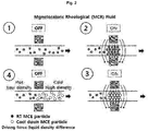
- FIG. 1 is a view showing a shape of a magnetorheological fluid before and after a magnetic field is applied
- FIG. 2 is a view showing the behavior of the magnetorheological fluid.
- the magnetorheological fluid is a suspension in which magnetic particles are dispersed in a nonmagnetic solution and exhibits magnetorheological phenomenon in which rheological behavior and electrical, thermal, mechanical, and physical properties are changed depending on the strength of a magnetic field externally applied.
- the magnetorheological fluid can control a mechanical force, for example, has a high yield stress of 10 to 100 kPa or more upon application of an external magnetic field and can control the mechanical force through application of the magnetic field without the need of an additional apparatus, thus simplifying the design of application apparatuses. Furthermore, altering the strength of the applied magnetic field can control the properties of the fluid. Accordingly, the rheological properties can be changed by controlling the magnetic field, thus precisely controlling the flow characteristic.
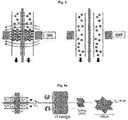
- FIG. 3 is a view showing metal wire feeding by using the magnetorheological fluid according to an embodiment of the present invention.
- the feeding of the metal wire includes holding the metal wire by applying the magnetic field to the magnetorheological fluid and then moving the metal wire; and feeding the metal wire to the molding device by removing the magnetic field from the magnetorheological fluid.
- the metal wire is moved in the magnetorheological fluid which behaves like a solid upon application of the magnetic field, and then when the magnetic field is removed, the metal wire is separated from the magnetorheological fluid, which behaves like a liquid, and fed to the molding device.
- FIG. 4A is a view showing a method of manufacturing a micro-molded product by using a metal wire according to the embodiment of the present invention
- FIG. 4B is a view showing a mold shape of an extrusion die.
- the manufacturing of the metal wire into the molded product includes extruding and cutting.
- the extruding is a step of extruding the metal wire into a mold shape of an extrusion die
- the cutting is a step of cutting the extruded wire into a size of a final micro-molded product.
- the metal wire may be a crystalline metal or alloy, or an amorphous metal or alloy. Furthermore, the temperature of the extrusion die is controlled to be included in a supercooled liquid temperature section of the amorphous metal or alloy or a high temperature deformation temperature section of the crystalline metal (for example, the superplasticity temperature or the softening temperature).
- the method further includes, before the cutting the extruded wire, rotating the extrusion die or the extruded wire to manufacture a micro-molded product in a helical shape.
- rotating the extrusion die or the extruded wire to manufacture a micro-molded product in a helical shape.
- the temperature of the extrusion die is controlled to a temperature between a glass transition temperature Tg and a crystallization temperature Tx of the amorphous alloy.
- the controlling of the temperature of the extrusion die to the temperature between the glass transition temperature Tg and the crystallization temperature Tx of the amorphous alloy makes it possible to manufacture a micro-molded product by using the amorphous alloy having excellent mechanical properties, material homogeneity, and moldability.
- the amorphous alloy wire into a micro-molded product by controlling the temperature of the extrusion die to the temperature between the glass transition temperature Tg and the crystallization temperature Tx of the amorphous alloy.
- the amorphous alloy in a supercooled liquid temperature section ⁇ Tx exhibits Newtonian viscous flow with low viscosity and little deformation limitation, rather than plastic deformation. In this section, it is not only possible to perform forming with a small load, but also perform microforming due to excellent moldability.
- the crystalline metal and alloy is softened at a high temperature to exhibit plastic deformation.
- a metal and an alloy which show superplastic deformation at a specific temperature section, are controlled in temperature, thus exhibiting an elongation of several hundred percent or more.
- An apparatus for manufacturing a micro-molded product by using a metal wire includes a forming part (not shown) and a metal wire feeding part.
- the forming part serves to manufacture the metal wire 10 into a molded product.
- the forming part includes: an extrusion die for extruding the metal wire into the shape of the molded product; and a cutting device for cutting the extruded wire into a size of a final micro-molded product and may further include a rotary motor for rotating the extrusion die or the extruded wire to manufacture a micro-molded product having a helical shape.
- the temperature of the forming part at the temperature of the section ⁇ T (section equal to or less than the crystallization temperature Tx) is maintained.
- the amorphous wire having a diameter of 10 ⁇ m to 500 ⁇ m is fed to a hot forming press having a groove that has a shape corresponding to a cross-section shape of the final micro-molded product, and then the molded product such as an extruded gear having a specific cross-section shape is cut to a desirable length.
- the extrusion die may use different molds having different grooves depending on the purpose, and the final micro-molded product may be 10 ⁇ m to 100 mm in length of each edge.
- the metal wire feeding part 100 feeds the metal wire by using a magnetorheological fluid.
- the metal wire feeding part feeds the metal wire 10 to the forming part by using the behavior of the magnetorheological fluid that behaves in response to application or interruption of a magnetic field.
- FIG. 7A is a cross-sectional view showing the metal wire feeding part according to the embodiment of the present invention
- FIG. 7B is a sectional view showing the metal wire feeding part according to the embodiment of the present invention.
- the metal wire feeding part 100 includes a gripper 110, an electromagnet 120, and a moving rail 130.
- the gripper 110 has a flexible dual-cylindrical structure composed of an inner tube 111 and an outer tube 112.
- the gripper is filled with the magnetorheological fluid 113 between the inner tube 111 and the outer tube 112, such that the metal wire 10 fed into the inner tube 111 is held through partial solidification of the magnetorheological fluid 113.
- FIGS. 8A and 8B are views showing a metal wire feeding method.
- the gripper 110 is configured such that only the inner tube 111 is made of a flexible material as shown in FIG. 8A , or both the inner and outer tubes 111 and 112 are made of a flexible material as shown in FIG. 8B .
- the inner tube 111 has to be made of a stretchable material such that the metal wire 10 fed into the inner tube 111 is held through partial solidification of the magnetorheological fluid 113.
- the electromagnets 120 are provided in a part of sectioned regions of the outer periphery of the outer tube 112 and allow the magnetorheological fluid 113 present in the gripper 110 to be attracted and solidified or to be dispersed through generation or removal of a magnetic field upon application or interruption of an electric current.
- the moving rail 130 moves the electromagnets 120 along a longitudinal direction of the outer tube. Accordingly, the metal wire 10 is moved in a state of being held by the magnetorheological fluid 113 in conjunction with movement of the electromagnets.
- FIG. 9 is a view showing a metal wire feeding part according to another embodiment of the present invention.
- the metal wire feeding part 100 includes a gripper 110 and electromagnets 120.
- the gripper 110 has a flexible dual-cylindrical structure composed of an inner tube 111 and an outer tube 112.
- the gripper is filled with a magnetorheological fluid 113 between the inner tube 111 and the outer tube 112, such that a metal wire 10 fed into the inner tube 111 is held through partial solidification of the magnetorheological fluid 113.
- the electromagnets 120 are provided on the outer periphery of the outer tube 112 in a longitudinal direction of the outer tube and allow the magnetorheological fluid 113 present in the gripper 110 to be attracted and solidified or to be dispersed through generation or removal of a magnetic field upon application or interruption of an electric current.
- the metal wire 10 When the electric current is applied to a part of sectioned regions of the electromagnets 120, the metal wire 10 is held by the magnetorheological fluid 112 being solidified. When the part of the sectioned regions to which the electric current is applied is moved, the metal wire 10 is moved along the inner tube 111. In other words, when the part of the sectioned regions of the electromagnets 120 to which the electric current is applied is moved in a moving direction of the metal wire 10, that is, in a direction toward a nozzle 140, the metal wire 10 is moved thereby.
- the method and apparatus for manufacturing the micro-molded product according to the present invention can manufacture a micro-molded product by using an amorphous or crystalline alloy having excellent mechanical properties, material homogeneity, and moldability. Furthermore, the magnetorheological fluid is used when a micro-metal wire is fed during microextrusion, whereby it is possible for the micro-metal wire to be fed without undergoing deformation or breakage.
- micro-parts having a size of several tens of micrometers to several millimeters in a three-dimensional shape and also to mass-produce micro-parts, thus significantly increasing the production amount of extrudable micro-parts such as micro-gears.
- the manufacturing of micro-gears using a conventional MEMS process has a large number of processes and takes a long time for each process, while having a high rate of occurrence of defective products, it takes a long time to obtain a finished product.
- extrusion molding on the basis of a conventional metal forming technology concept makes it possible for a product to be freely formed in a short period of time within the durability of a mold.
- micro-parts such as micro-gears by using a minimum number of devices such as a piezoelectric actuator, a thermocouple, and a heater controller.
- the micro-molded product manufactured by using the metal wire according to the present invention can find wide application, such as in microrobots, micro-system parts, biomedical system parts, electronic device parts, and the like.
- metal wire 100 metal wire feeding part 110: gripper 111: inner tube 112: outer tube 113: magnetorheological fluid 120: electromagnet 130: moving rail 140: nozzle
Landscapes
- Engineering & Computer Science (AREA)
- Mechanical Engineering (AREA)
- Manufacturing & Machinery (AREA)
- Microelectronics & Electronic Packaging (AREA)
- Micromachines (AREA)
- Metal Extraction Processes (AREA)
Abstract
Description
- The present invention relates generally to a method and an apparatus for manufacturing a micro-molded product by using a metal wire. More particularly, the present invention relates to a method and an apparatus for manufacturing a micro-molded product by using a metal wire, wherein a molding temperature is controlled to be included in a supercooled liquid temperature section or a specific high temperature deformation temperature section of the metal wire.
- As well known in the art, microforming is a method for mass production of micro-parts, including microextrusion (gear, shaft, and the like), blow molding (various three-dimensional plate parts), embossing, and microstamping (nano-/micro-scaled surface patterns), and is a technique for forming nano-/micro-scaled surface patterns or for manufacturing metal micro-parts that can be applied to nano-/micro-systems.
- Manufacturing of micro-parts using microforming can increase price competitiveness through mass production and also make it possible to manufacture three-dimensional micro-parts having a size of several tens of micrometers to several millimeters, which are difficult to be formed by a conventional manufacturing method and thus are manufactured only by MEMS or lithography.
- Most metal alloys form a crystalline phase having an ordered atomic arrangement upon being solidified from a liquid phase. However, some alloys can maintain their disordered atomic structure of the liquid phase in a solid phase when the cooling rate applied to the solidification is high enough to exceed a critical value and to limit nucleation and growth of the crystalline phase. These alloys are generally called amorphous alloys or metallic glasses.
- An amorphous metal has a much higher tensile strength than a crystalline metal due to the characteristics of an atomic structure and has other excellent properties such as toughness and corrosion resistance and is thus used in microforming.
- The superplastic deformation of materials is a phenomenon in which deformation stability is increased at a specific deformation condition (temperature, strain rate, and the like), thus exhibiting a high elongation of several hundred percent or more. Superplastically deformed material exhibits a low flow stress of several MPa. When superplastic deformation is used in the industrial field, even complex parts can be easily manufactured with a low processing force, leading to a great increase in degree of freedom of parts design.
- However, in microextrusion, when a metal alloy wire having superplastic deformation behavior and an amorphous metal are fed, the wire is deformed or broken. This results in a problem of feeding raw materials for microforming, and thus it is necessary to develop technology to solve this problem.
- (Patent Document 1) Korean Patent No.
10-0893574 - Accordingly, the present invention has been made keeping in mind the above problems occurring in the related art, and an objective of the present invention is to provide a method of manufacturing a micro-molded product by using a metal wire, wherein a molding temperature is controlled to be included in a supercooled liquid temperature section or a specific high temperature deformation temperature section of the metal wire, thus providing excellent mechanical properties, material homogeneity, and moldability.
- Another objective of the present invention is to provide an apparatus for manufacturing a micro-molded product by using a metal wire, wherein a magnetorheological fluid (MR fluid) is used when a micro-wire is fed during microextrusion, whereby the wire is fed without undergoing deformation or breakage.
- Still another objective of the present invention is to provide a micro-molded product, wherein three-dimensional micro-parts are manufactured in a size of several tens of micrometers to several millimeters and thus mass-production thereof is possible, thus finding application in microrobots, micro-system parts, biomedical system parts, electronic device parts, and the like.
- However, the above objectives are described only for illustrative purposes and should not be construed as limiting the spirit and scope of the present invention.
- In order to accomplish the above objectives, there is provided a method of manufacturing a micro-molded product by using a metal wire, the method including: feeding the metal wire to a molding device by using a magnetorheological fluid (MR fluid); and manufacturing the metal wire into a molded product.
- The feeding of the metal wire may include: holding the metal wire by applying a magnetic field to the magnetorheological fluid and then moving the metal wire; and feeding the metal wire to the molding device by removing the magnetic field.
- The manufacturing of the metal wire into the molded product may include: extruding the metal wire by using an extrusion die having a shape corresponding to a shape of the molded product; and cutting the extruded metal wire into a size of a final micro-molded product.
- The method may further include, before the cutting the extruded metal wire, rotating the extrusion die or the extruded wire to manufacture the micro-molded product in a helical shape.
- The metal wire may have a diameter of 10 µm to 500 µm.
- The metal wire may be a crystalline metal or alloy, or an amorphous metal or alloy.
- A temperature of the extrusion die may be controlled to be included in a supercooled liquid temperature section of the amorphous metal or alloy or a high temperature deformation temperature section of the crystalline metal.
- According to another aspect of the present invention, there is provided an apparatus for manufacturing a micro-molded product by using a metal wire, the apparatus including: a metal wire feeding part feeding the metal wire by using a magnetorheological fluid (MR fluid); and a forming part manufacturing the fed metal wire into a molded-product.
- The metal wire feeding part may include: a gripper having a flexible dual-cylindrical structure and holding the metal wire through partial solidification of the magnetorheological fluid that is filled in the gripper; an electromagnet provided in a part of sectioned regions of an outer periphery of the gripper; and a moving rail moving the electromagnet along a longitudinal direction of the gripper, wherein the metal wire may be moved in a held state in conjunction with movement of the electromagnet.
- The metal wire feeding part may include: a gripper having a flexible dual-cylindrical structure and holding the metal wire through partial solidification of the magnetorheological fluid that is filled in the gripper; and an electromagnet provided on an outer periphery of the gripper in a longitudinal direction of the gripper, wherein when an electric current is applied to a part of sectioned regions of the electromagnet, the metal wire may be held, and when the part of the sectioned regions to which the electric current is applied is moved, the metal wire may be moved thereby.
- The forming part may include: an extrusion die extruding the metal wire into a shape of a molded product; and a cutting device cutting the extruded wire into a size of a final micro-molded product.
- The apparatus may further include a rotary motor rotating the extrusion die or the extruded wire to manufacture a micro-molded product having a helical shape.
- According to a method and an apparatus for manufacturing a micro-molded product by using a metal wire according to the present invention, it is possible to control a molding temperature to be included in a supercooled liquid temperature section or a specific high temperature deformation temperature section of the metal wire, thus providing excellent mechanical properties, material homogeneity, and moldability.
- Furthermore, a magnetorheological fluid (MR fluid) is used when a micro-wire is fed during microextrusion, whereby it is possible for the wire to be fed without undergoing deformation or breakage.
- Furthermore, it is possible to manufacture three-dimensional micro-parts having a size of several tens of micrometers to several millimeters and thus mass production thereof is possible, thus finding application in microrobots, micro-system parts, biomedical system parts, electronic device parts, and the like.
- The above effects of the present invention are described only for illustrative purposes and should not be construed as limiting the present invention.
-
-
FIG. 1 is a view showing a shape of a magnetorheological fluid before and after a magnetic field is applied. -
FIG. 2 is a view showing a behavior of the magnetorheological fluid. -
FIG. 3 is a view showing metal wire feeding by using the magnetorheological fluid according to an embodiment of the present invention. -
FIG. 4A is a view showing a method of manufacturing a micro-molded product by using a metal wire according to the embodiment of the present invention. -
FIG. 4B is a view showing a mold shape of an extrusion die. -
FIG. 5 is a view showing a typical DSC curve (schematic) for an amorphous alloy. -
FIG. 6 is a view showing an amorphous alloy wire and a crystallization temperature thereof. -
FIG. 7A is a cross-sectional view showing a metal wire feeding part according to the embodiment of the present invention. -
FIG. 7B is a sectional view showing the metal wire feeding part according to the embodiment of the present invention. -
FIG. 8A is a view showing a metal wire feeding method in which an inner tube of a gripper according to the embodiment of the present invention is made of a flexible material. -
FIG. 8B is a view showing the metal wire feeding method in which the inner tube and an outer tube of the gripper according to the embodiment of the present invention are made of a flexible material. - FIG. 9 is a view showing a metal wire feeding part according to another embodiment of the present invention.
- Hereinbelow, exemplary embodiments of the present invention will be described in detail with reference to the accompanying drawings. The embodiments of the present invention are presented to make complete disclosure of the present invention and help those who are ordinarily skilled in the art best understand the invention. Various changes to the following embodiments are possible and the scope of the present invention is not limited to the following embodiments. The expression "and/or" is interpreted to include each of enumerated items, and all combinations including one or more items selected from among the enumerated items. The same reference numerals are used throughout the different drawings to designate the same or similar components. Further, various elements and regions in the drawings are schematically drawn. Accordingly, the spirit and the scope of the present invention are not limited by the relative size or spacing drawn in the accompanying drawings.
- Microforming is a method for mass production of micro-parts, including microextrusion (gear, shaft, and the like), blow molding (various three-dimensional plate parts), embossing, and microstamping (nano-/micro-scaled surface patterns), and is a technique for forming nano-/micro-scaled surface patterns or for manufacturing metal micro-parts that can be applied to nano-/micro-systems.
- A method of manufacturing a micro-molded product by using a metal wire according to the present invention includes: feeding the metal wire to a molding device by using a magnetorheological fluid (MR fluid); and manufacturing the metal wire into a molded product. The metal wire may have a diameter of 10 µm to 500 µm and may be a micro-wire. The magnetorheological fluid may include a magneto-caloric rheological fluid.
- The feeding of the metal wire is a step of feeding the metal wire to the molding device by using the behavior of the magnetorheological fluid that behaves in response to application or interruption of a magnetic field. The feeding of the metal wire includes: holding the metal wire by applying the magnetic field to the magnetorheological fluid and then moving the metal wire; and feeding the metal wire to the molding device by removing the magnetic field from the magnetorheological fluid.
- The magnetorheological fluid, which is a material of which rheological properties are rapidly changed by application of a magnetic field, changes to a solid having a high yield strength from a freely flowable liquid upon application of a magnetic field.
-
FIG. 1 is a view showing a shape of a magnetorheological fluid before and after a magnetic field is applied, andFIG. 2 is a view showing the behavior of the magnetorheological fluid. For example, as shown inFIGS. 1 and2 , the magnetorheological fluid is a suspension in which magnetic particles are dispersed in a nonmagnetic solution and exhibits magnetorheological phenomenon in which rheological behavior and electrical, thermal, mechanical, and physical properties are changed depending on the strength of a magnetic field externally applied. - The magnetorheological fluid can control a mechanical force, for example, has a high yield stress of 10 to 100 kPa or more upon application of an external magnetic field and can control the mechanical force through application of the magnetic field without the need of an additional apparatus, thus simplifying the design of application apparatuses. Furthermore, altering the strength of the applied magnetic field can control the properties of the fluid. Accordingly, the rheological properties can be changed by controlling the magnetic field, thus precisely controlling the flow characteristic.
- As a result, when the micro-wire is fed by using the magnetorheological fluid to manufacture the micro-molded product, it is possible for the wire to be fed without undergoing deformation or breakage.
-
FIG. 3 is a view showing metal wire feeding by using the magnetorheological fluid according to an embodiment of the present invention. The feeding of the metal wire includes holding the metal wire by applying the magnetic field to the magnetorheological fluid and then moving the metal wire; and feeding the metal wire to the molding device by removing the magnetic field from the magnetorheological fluid. The metal wire is moved in the magnetorheological fluid which behaves like a solid upon application of the magnetic field, and then when the magnetic field is removed, the metal wire is separated from the magnetorheological fluid, which behaves like a liquid, and fed to the molding device. -
FIG. 4A is a view showing a method of manufacturing a micro-molded product by using a metal wire according to the embodiment of the present invention, andFIG. 4B is a view showing a mold shape of an extrusion die. The manufacturing of the metal wire into the molded product includes extruding and cutting. The extruding is a step of extruding the metal wire into a mold shape of an extrusion die, and the cutting is a step of cutting the extruded wire into a size of a final micro-molded product. - The metal wire may be a crystalline metal or alloy, or an amorphous metal or alloy. Furthermore, the temperature of the extrusion die is controlled to be included in a supercooled liquid temperature section of the amorphous metal or alloy or a high temperature deformation temperature section of the crystalline metal (for example, the superplasticity temperature or the softening temperature).
- Furthermore, the method further includes, before the cutting the extruded wire, rotating the extrusion die or the extruded wire to manufacture a micro-molded product in a helical shape. In other words, during a process of cooling the molten amorphous metal or alloy, a molding device, the die, and the wire are rotated, thus manufacturing a helical-shaped gear.
- Furthermore, the temperature of the extrusion die is controlled to a temperature between a glass transition temperature Tg and a crystallization temperature Tx of the amorphous alloy. The controlling of the temperature of the extrusion die to the temperature between the glass transition temperature Tg and the crystallization temperature Tx of the amorphous alloy makes it possible to manufacture a micro-molded product by using the amorphous alloy having excellent mechanical properties, material homogeneity, and moldability.
-
FIG. 5 is a view showing a typical DSC curve (schematic) for the amorphous alloy, andFIG. 6 is a view showing an amorphous alloy wire and the crystallization temperature thereof. The amorphous alloy, which is produced by a manufacturing process in which a liquid alloy is rapidly cooled and solidified without being crystallized under a supercooled state while being cooled below a melting point, has excellent mechanical properties, material homogeneity, and moldability. The amorphous alloy wire may be a commercially available amorphous wire and is formed in a specific temperature section ΔT (a section equal to or less than the crystallization temperature Tx). - As a result, it is possible to form the amorphous alloy wire into a micro-molded product by controlling the temperature of the extrusion die to the temperature between the glass transition temperature Tg and the crystallization temperature Tx of the amorphous alloy. The amorphous alloy in a supercooled liquid temperature section ΔTx exhibits Newtonian viscous flow with low viscosity and little deformation limitation, rather than plastic deformation. In this section, it is not only possible to perform forming with a small load, but also perform microforming due to excellent moldability.
- Furthermore, the crystalline metal and alloy is softened at a high temperature to exhibit plastic deformation. In particular, a metal and an alloy, which show superplastic deformation at a specific temperature section, are controlled in temperature, thus exhibiting an elongation of several hundred percent or more.
- An apparatus for manufacturing a micro-molded product by using a metal wire includes a forming part (not shown) and a metal wire feeding part.
- The forming part serves to manufacture the
metal wire 10 into a molded product. The forming part includes: an extrusion die for extruding the metal wire into the shape of the molded product; and a cutting device for cutting the extruded wire into a size of a final micro-molded product and may further include a rotary motor for rotating the extrusion die or the extruded wire to manufacture a micro-molded product having a helical shape. - When forming an amorphous metal or alloy, the temperature of the forming part at the temperature of the section ΔT (section equal to or less than the crystallization temperature Tx) is maintained. The amorphous wire having a diameter of 10 µm to 500 µm is fed to a hot forming press having a groove that has a shape corresponding to a cross-section shape of the final micro-molded product, and then the molded product such as an extruded gear having a specific cross-section shape is cut to a desirable length. The extrusion die may use different molds having different grooves depending on the purpose, and the final micro-molded product may be 10 µm to 100 mm in length of each edge.
- The metal
wire feeding part 100 feeds the metal wire by using a magnetorheological fluid. The metal wire feeding part feeds themetal wire 10 to the forming part by using the behavior of the magnetorheological fluid that behaves in response to application or interruption of a magnetic field. -
FIG. 7A is a cross-sectional view showing the metal wire feeding part according to the embodiment of the present invention, andFIG. 7B is a sectional view showing the metal wire feeding part according to the embodiment of the present invention. The metalwire feeding part 100 includes agripper 110, anelectromagnet 120, and a movingrail 130. - The
gripper 110 has a flexible dual-cylindrical structure composed of aninner tube 111 and anouter tube 112. The gripper is filled with themagnetorheological fluid 113 between theinner tube 111 and theouter tube 112, such that themetal wire 10 fed into theinner tube 111 is held through partial solidification of themagnetorheological fluid 113. -
FIGS. 8A and8B are views showing a metal wire feeding method. Thegripper 110 is configured such that only theinner tube 111 is made of a flexible material as shown inFIG. 8A , or both the inner andouter tubes FIG. 8B . Theinner tube 111 has to be made of a stretchable material such that themetal wire 10 fed into theinner tube 111 is held through partial solidification of themagnetorheological fluid 113. - The
electromagnets 120 are provided in a part of sectioned regions of the outer periphery of theouter tube 112 and allow themagnetorheological fluid 113 present in thegripper 110 to be attracted and solidified or to be dispersed through generation or removal of a magnetic field upon application or interruption of an electric current. - The moving
rail 130 moves theelectromagnets 120 along a longitudinal direction of the outer tube. Accordingly, themetal wire 10 is moved in a state of being held by themagnetorheological fluid 113 in conjunction with movement of the electromagnets. - FIG. 9 is a view showing a metal wire feeding part according to another embodiment of the present invention. The metal
wire feeding part 100 includes agripper 110 andelectromagnets 120. - The
gripper 110 has a flexible dual-cylindrical structure composed of aninner tube 111 and anouter tube 112. The gripper is filled with amagnetorheological fluid 113 between theinner tube 111 and theouter tube 112, such that ametal wire 10 fed into theinner tube 111 is held through partial solidification of themagnetorheological fluid 113. - The
electromagnets 120 are provided on the outer periphery of theouter tube 112 in a longitudinal direction of the outer tube and allow themagnetorheological fluid 113 present in thegripper 110 to be attracted and solidified or to be dispersed through generation or removal of a magnetic field upon application or interruption of an electric current. - When the electric current is applied to a part of sectioned regions of the
electromagnets 120, themetal wire 10 is held by themagnetorheological fluid 112 being solidified. When the part of the sectioned regions to which the electric current is applied is moved, themetal wire 10 is moved along theinner tube 111. In other words, when the part of the sectioned regions of theelectromagnets 120 to which the electric current is applied is moved in a moving direction of themetal wire 10, that is, in a direction toward anozzle 140, themetal wire 10 is moved thereby. - The method and apparatus for manufacturing the micro-molded product according to the present invention can manufacture a micro-molded product by using an amorphous or crystalline alloy having excellent mechanical properties, material homogeneity, and moldability. Furthermore, the magnetorheological fluid is used when a micro-metal wire is fed during microextrusion, whereby it is possible for the micro-metal wire to be fed without undergoing deformation or breakage.
- Furthermore, it is possible to manufacture micro-parts having a size of several tens of micrometers to several millimeters in a three-dimensional shape and also to mass-produce micro-parts, thus significantly increasing the production amount of extrudable micro-parts such as micro-gears. Because the manufacturing of micro-gears using a conventional MEMS process has a large number of processes and takes a long time for each process, while having a high rate of occurrence of defective products, it takes a long time to obtain a finished product. However, the use of extrusion molding on the basis of a conventional metal forming technology concept makes it possible for a product to be freely formed in a short period of time within the durability of a mold.
- Furthermore, in manufacturing of micro gears using the MEMS process, large devices such as a spin coater (JC-101), a mask aligner (MA6), a non-MESC Multiplex ICP, and a wet station are required in processes such as PR coating, exposure, dry, and etching. However, through the use of extrusion molding, it is possible to manufacture micro-parts such as micro-gears by using a minimum number of devices such as a piezoelectric actuator, a thermocouple, and a heater controller.
- In other words, it is possible to solve problems such as high manufacturing cost, long process time, shortage of production facilities, limited use of materials, and the like, which are disadvantages of a conventional printing method. Furthermore, when the apparatus for manufacturing the micro-molded product according to the present invention is used, manufacturing cost other than mold manufacturing cost is low, which is advantageous over the conventional MEMS process.
- Accordingly, the micro-molded product manufactured by using the metal wire according to the present invention can find wide application, such as in microrobots, micro-system parts, biomedical system parts, electronic device parts, and the like.
- Although the exemplary embodiments of the present invention have been described for illustrative purposes, those skilled in the art will appreciate that various modifications, additions and substitutions are possible, without departing from the scope and spirit of the invention as disclosed in the accompanying claims.
-
<Description of the Reference Numerals in the Drawings> 10: metal wire 100: metal wire feeding part 110: gripper 111: inner tube 112: outer tube 113: magnetorheological fluid 120: electromagnet 130: moving rail 140: nozzle
Claims (12)
- A method of manufacturing a micro-molded product by using a metal wire, the method comprising:feeding the metal wire to a molding device by using a magnetorheological fluid (MR fluid); andmanufacturing the metal wire into a molded product.
- The method of claim 1, wherein the feeding of the metal wire includes:holding the metal wire by applying a magnetic field to the magnetorheological fluid and then moving the metal wire; andfeeding the metal wire to the molding device by removing the magnetic field.
- The method of claim 1, wherein the manufacturing of the metal wire into the molded product includes:extruding the metal wire by using an extrusion die having a shape corresponding to a shape of the molded product; andcutting the extruded metal wire into a size of a final micro-molded product.
- The method of claim 3, further comprising:before the cutting the extruded metal wire,rotating the extrusion die or the extruded wire to manufacture the micro-molded product in a helical shape.
- The method of claim 1, wherein the metal wire has a diameter of 10 µm to 500 µm.
- The method of claim 3, wherein the metal wire is a crystalline metal or alloy, or an amorphous metal or alloy.
- The method of claim 6, wherein a temperature of the extrusion die is controlled to be included in a supercooled liquid temperature section of the amorphous metal or alloy or a high temperature deformation temperature section of the crystalline metal.
- An apparatus for manufacturing a micro-molded product by using a metal wire, the apparatus comprising:a metal wire feeding part feeding the metal wire by using a magnetorheological fluid (MR fluid); anda forming part manufacturing the fed metal wire into a molded-product.
- The apparatus of claim 8, wherein the metal wire feeding part includes:a gripper having a flexible dual-cylindrical structure and holding the metal wire through partial solidification of the magnetorheological fluid that is filled in the gripper;an electromagnet provided in a part of sectioned regions of an outer periphery of the gripper; anda moving rail moving the electromagnet along a longitudinal direction of the gripper,wherein the metal wire is moved in a held state in conjunction with movement of the electromagnet.
- The apparatus of claim 8, wherein the metal wire feeding part includes:a gripper having a flexible dual-cylindrical structure and holding the metal wire through partial solidification of the magnetorheological fluid that is filled in the gripper; andan electromagnet provided on an outer periphery of the gripper in a longitudinal direction of the gripper,wherein when an electric current is applied to a part of sectioned regions of the electromagnet, the metal wire is held, and when the part of the sectioned regions to which the electric current is applied is moved, the metal wire is moved thereby.
- The apparatus of claim 8, wherein the forming part includes:an extrusion die extruding the metal wire into a shape of a molded product; anda cutting device cutting the extruded wire into a size of a final micro-molded product.
- The apparatus of claim 11, further comprising:
a rotary motor rotating the extrusion die or the extruded wire to manufacture a micro-molded product having a helical shape.
Applications Claiming Priority (2)
| Application Number | Priority Date | Filing Date | Title |
|---|---|---|---|
| KR1020160105688A KR101839689B1 (en) | 2016-08-19 | 2016-08-19 | Method for manufacturing and device for manufacturing micro-size extruded article using amorphous alloy wire |
| PCT/KR2017/004257 WO2018034408A1 (en) | 2016-08-19 | 2017-04-21 | Method and apparatus for manufacturing micro-molded product by using metal wire |
Publications (3)
| Publication Number | Publication Date |
|---|---|
| EP3502046A1 true EP3502046A1 (en) | 2019-06-26 |
| EP3502046A4 EP3502046A4 (en) | 2019-08-14 |
| EP3502046B1 EP3502046B1 (en) | 2023-05-03 |
Family
ID=61196849
Family Applications (1)
| Application Number | Title | Priority Date | Filing Date |
|---|---|---|---|
| EP17841592.3A Active EP3502046B1 (en) | 2016-08-19 | 2017-04-21 | Method and apparatus for manufacturing micro-molded product by using metal wire |
Country Status (3)
| Country | Link |
|---|---|
| EP (1) | EP3502046B1 (en) |
| KR (1) | KR101839689B1 (en) |
| WO (1) | WO2018034408A1 (en) |
Family Cites Families (9)
| Publication number | Priority date | Publication date | Assignee | Title |
|---|---|---|---|---|
| US6123788A (en) * | 1993-04-19 | 2000-09-26 | Electrocopper Products Limited | Copper wire and process for making copper wire |
| US5970581A (en) | 1998-06-22 | 1999-10-26 | Bic Corporation | Controllable fluid gripping devices |
| US6537471B2 (en) * | 1999-12-14 | 2003-03-25 | Microhelix, Inc. | Method for producing ultra thin wall extrusions |
| KR100623348B1 (en) * | 2005-03-08 | 2006-09-13 | 엘에스전선 주식회사 | Chiller of extrusion die |
| KR100893574B1 (en) * | 2007-02-15 | 2009-04-17 | 부산대학교 산학협력단 | Extrusion apparatus for manufacturing micro parts |
| DE102007017588A1 (en) * | 2007-04-13 | 2008-10-16 | Fraunhofer-Gesellschaft zur Förderung der angewandten Forschung e.V. | Blocking device with field-controllable fluid |
| KR20090115471A (en) * | 2008-05-02 | 2009-11-05 | 한국과학기술원 | Apparatus and method for grain refinement of tubular material using ECA process |
| US9248484B2 (en) * | 2010-07-06 | 2016-02-02 | Alfred R. Austen | Method and apparatus for applying uniaxial compression stresses to a moving wire |
| KR101659584B1 (en) * | 2015-01-22 | 2016-09-23 | 주식회사 다원시스 | Hybrid heating method and system for filler wire process |
-
2016
- 2016-08-19 KR KR1020160105688A patent/KR101839689B1/en active Active
-
2017
- 2017-04-21 EP EP17841592.3A patent/EP3502046B1/en active Active
- 2017-04-21 WO PCT/KR2017/004257 patent/WO2018034408A1/en not_active Ceased
Also Published As
| Publication number | Publication date |
|---|---|
| KR20180020785A (en) | 2018-02-28 |
| EP3502046A4 (en) | 2019-08-14 |
| KR101839689B1 (en) | 2018-03-16 |
| WO2018034408A1 (en) | 2018-02-22 |
| EP3502046B1 (en) | 2023-05-03 |
Similar Documents
| Publication | Publication Date | Title |
|---|---|---|
| DE69838178T2 (en) | METHOD AND DEVICE FOR PATIENT CRYSTALLIZATION AMORPHIDE PLASTIC OBJECTS | |
| CN103443321B (en) | The injection molding of the metallic glass undertaken by rapid capacitor discharge | |
| EP2825331A1 (en) | Multi step processing method for the fabrication of complex articles made of metallic glasses | |
| CN108728779B (en) | A flexible forming system and forming method for an amorphous alloy plate | |
| EP3181267B1 (en) | Method for integrally forming non-metal part and metal part | |
| JP2019535636A (en) | Addition manufacturing system and glass article manufacturing method | |
| CN109317528A (en) | A metal alloy material extrusion die | |
| CN104226777B (en) | A kind of deep camber thin-wall member resisting medium external pressure shaping method | |
| KR20120038964A (en) | Device and method for producing thick-walled plastic molded parts having reduced shrinkage sites by injection molding or embossing | |
| JP2017024011A (en) | Magnesium-based alloy pipe and method for manufacturing the same | |
| EP3502046B1 (en) | Method and apparatus for manufacturing micro-molded product by using metal wire | |
| CN103582616B (en) | The shaped device of glass ware forming product | |
| KR20160086946A (en) | A method and system for fabricating bulk metallic glass sheets | |
| CN101801862A (en) | Method for producing glass molded body | |
| TWI589535B (en) | Forming die set, and optical element manufacturing method | |
| US20160318095A1 (en) | Molding and De-Molding of Metallic Glass Using Non-Disposable Molds | |
| CN103343309B (en) | Method for manufacturing memory alloy spacecraft unlocking drive element | |
| CN105344972B (en) | A kind of quick forming method of non-crystaline amorphous metal part | |
| CN101722204A (en) | Extrusion process for titanium alloy profile material | |
| KR100893574B1 (en) | Extrusion apparatus for manufacturing micro parts | |
| Anyasodor et al. | Investigations into fundamentals and forming system design for micro-tube expansion with pressurized media | |
| CN103911562A (en) | Non-phosphorus palladium-based block metal glass with wide supercooled liquid region and preparation method thereof | |
| CN108908932A (en) | A kind of auxiliary thermal of 3D printer based on continuous temperature control between multi-region | |
| WO2014182258A2 (en) | Construction element based on single and multilayered metal glass and method of production of thereof | |
| US10941472B2 (en) | Systems and methods for drawing high aspect ratio metallic glass-based materials |
Legal Events
| Date | Code | Title | Description |
|---|---|---|---|
| STAA | Information on the status of an ep patent application or granted ep patent |
Free format text: STATUS: THE INTERNATIONAL PUBLICATION HAS BEEN MADE |
|
| PUAI | Public reference made under article 153(3) epc to a published international application that has entered the european phase |
Free format text: ORIGINAL CODE: 0009012 |
|
| STAA | Information on the status of an ep patent application or granted ep patent |
Free format text: STATUS: REQUEST FOR EXAMINATION WAS MADE |
|
| 17P | Request for examination filed |
Effective date: 20190318 |
|
| AK | Designated contracting states |
Kind code of ref document: A1 Designated state(s): AL AT BE BG CH CY CZ DE DK EE ES FI FR GB GR HR HU IE IS IT LI LT LU LV MC MK MT NL NO PL PT RO RS SE SI SK SM TR |
|
| AX | Request for extension of the european patent |
Extension state: BA ME |
|
| A4 | Supplementary search report drawn up and despatched |
Effective date: 20190711 |
|
| RIC1 | Information provided on ipc code assigned before grant |
Ipc: B21C 25/00 20060101ALI20190705BHEP Ipc: B21F 3/02 20060101ALI20190705BHEP Ipc: B21C 23/00 20060101ALI20190705BHEP Ipc: B21F 13/00 20060101ALI20190705BHEP Ipc: B81C 99/00 20100101AFI20190705BHEP |
|
| DAV | Request for validation of the european patent (deleted) | ||
| DAX | Request for extension of the european patent (deleted) | ||
| STAA | Information on the status of an ep patent application or granted ep patent |
Free format text: STATUS: EXAMINATION IS IN PROGRESS |
|
| 17Q | First examination report despatched |
Effective date: 20210723 |
|
| GRAP | Despatch of communication of intention to grant a patent |
Free format text: ORIGINAL CODE: EPIDOSNIGR1 |
|
| STAA | Information on the status of an ep patent application or granted ep patent |
Free format text: STATUS: GRANT OF PATENT IS INTENDED |
|
| INTG | Intention to grant announced |
Effective date: 20230126 |
|
| GRAS | Grant fee paid |
Free format text: ORIGINAL CODE: EPIDOSNIGR3 |
|
| GRAA | (expected) grant |
Free format text: ORIGINAL CODE: 0009210 |
|
| STAA | Information on the status of an ep patent application or granted ep patent |
Free format text: STATUS: THE PATENT HAS BEEN GRANTED |
|
| AK | Designated contracting states |
Kind code of ref document: B1 Designated state(s): AL AT BE BG CH CY CZ DE DK EE ES FI FR GB GR HR HU IE IS IT LI LT LU LV MC MK MT NL NO PL PT RO RS SE SI SK SM TR |
|
| REG | Reference to a national code |
Ref country code: GB Ref legal event code: FG4D |
|
| REG | Reference to a national code |
Ref country code: DE Ref legal event code: R096 Ref document number: 602017068403 Country of ref document: DE |
|
| REG | Reference to a national code |
Ref country code: AT Ref legal event code: REF Ref document number: 1564470 Country of ref document: AT Kind code of ref document: T Effective date: 20230515 Ref country code: CH Ref legal event code: EP |
|
| REG | Reference to a national code |
Ref country code: IE Ref legal event code: FG4D |
|
| REG | Reference to a national code |
Ref country code: LT Ref legal event code: MG9D |
|
| REG | Reference to a national code |
Ref country code: NL Ref legal event code: MP Effective date: 20230503 |
|
| REG | Reference to a national code |
Ref country code: AT Ref legal event code: MK05 Ref document number: 1564470 Country of ref document: AT Kind code of ref document: T Effective date: 20230503 |
|
| P01 | Opt-out of the competence of the unified patent court (upc) registered |
Effective date: 20230907 |
|
| PG25 | Lapsed in a contracting state [announced via postgrant information from national office to epo] |
Ref country code: SE Free format text: LAPSE BECAUSE OF FAILURE TO SUBMIT A TRANSLATION OF THE DESCRIPTION OR TO PAY THE FEE WITHIN THE PRESCRIBED TIME-LIMIT Effective date: 20230503 Ref country code: PT Free format text: LAPSE BECAUSE OF FAILURE TO SUBMIT A TRANSLATION OF THE DESCRIPTION OR TO PAY THE FEE WITHIN THE PRESCRIBED TIME-LIMIT Effective date: 20230904 Ref country code: NO Free format text: LAPSE BECAUSE OF FAILURE TO SUBMIT A TRANSLATION OF THE DESCRIPTION OR TO PAY THE FEE WITHIN THE PRESCRIBED TIME-LIMIT Effective date: 20230803 Ref country code: NL Free format text: LAPSE BECAUSE OF FAILURE TO SUBMIT A TRANSLATION OF THE DESCRIPTION OR TO PAY THE FEE WITHIN THE PRESCRIBED TIME-LIMIT Effective date: 20230503 Ref country code: ES Free format text: LAPSE BECAUSE OF FAILURE TO SUBMIT A TRANSLATION OF THE DESCRIPTION OR TO PAY THE FEE WITHIN THE PRESCRIBED TIME-LIMIT Effective date: 20230503 Ref country code: AT Free format text: LAPSE BECAUSE OF FAILURE TO SUBMIT A TRANSLATION OF THE DESCRIPTION OR TO PAY THE FEE WITHIN THE PRESCRIBED TIME-LIMIT Effective date: 20230503 |
|
| PG25 | Lapsed in a contracting state [announced via postgrant information from national office to epo] |
Ref country code: RS Free format text: LAPSE BECAUSE OF FAILURE TO SUBMIT A TRANSLATION OF THE DESCRIPTION OR TO PAY THE FEE WITHIN THE PRESCRIBED TIME-LIMIT Effective date: 20230503 Ref country code: PL Free format text: LAPSE BECAUSE OF FAILURE TO SUBMIT A TRANSLATION OF THE DESCRIPTION OR TO PAY THE FEE WITHIN THE PRESCRIBED TIME-LIMIT Effective date: 20230503 Ref country code: LV Free format text: LAPSE BECAUSE OF FAILURE TO SUBMIT A TRANSLATION OF THE DESCRIPTION OR TO PAY THE FEE WITHIN THE PRESCRIBED TIME-LIMIT Effective date: 20230503 Ref country code: LT Free format text: LAPSE BECAUSE OF FAILURE TO SUBMIT A TRANSLATION OF THE DESCRIPTION OR TO PAY THE FEE WITHIN THE PRESCRIBED TIME-LIMIT Effective date: 20230503 Ref country code: IS Free format text: LAPSE BECAUSE OF FAILURE TO SUBMIT A TRANSLATION OF THE DESCRIPTION OR TO PAY THE FEE WITHIN THE PRESCRIBED TIME-LIMIT Effective date: 20230903 Ref country code: HR Free format text: LAPSE BECAUSE OF FAILURE TO SUBMIT A TRANSLATION OF THE DESCRIPTION OR TO PAY THE FEE WITHIN THE PRESCRIBED TIME-LIMIT Effective date: 20230503 Ref country code: GR Free format text: LAPSE BECAUSE OF FAILURE TO SUBMIT A TRANSLATION OF THE DESCRIPTION OR TO PAY THE FEE WITHIN THE PRESCRIBED TIME-LIMIT Effective date: 20230804 |
|
| PG25 | Lapsed in a contracting state [announced via postgrant information from national office to epo] |
Ref country code: FI Free format text: LAPSE BECAUSE OF FAILURE TO SUBMIT A TRANSLATION OF THE DESCRIPTION OR TO PAY THE FEE WITHIN THE PRESCRIBED TIME-LIMIT Effective date: 20230503 |
|
| PG25 | Lapsed in a contracting state [announced via postgrant information from national office to epo] |
Ref country code: SK Free format text: LAPSE BECAUSE OF FAILURE TO SUBMIT A TRANSLATION OF THE DESCRIPTION OR TO PAY THE FEE WITHIN THE PRESCRIBED TIME-LIMIT Effective date: 20230503 |
|
| PG25 | Lapsed in a contracting state [announced via postgrant information from national office to epo] |
Ref country code: SM Free format text: LAPSE BECAUSE OF FAILURE TO SUBMIT A TRANSLATION OF THE DESCRIPTION OR TO PAY THE FEE WITHIN THE PRESCRIBED TIME-LIMIT Effective date: 20230503 Ref country code: SK Free format text: LAPSE BECAUSE OF FAILURE TO SUBMIT A TRANSLATION OF THE DESCRIPTION OR TO PAY THE FEE WITHIN THE PRESCRIBED TIME-LIMIT Effective date: 20230503 Ref country code: RO Free format text: LAPSE BECAUSE OF FAILURE TO SUBMIT A TRANSLATION OF THE DESCRIPTION OR TO PAY THE FEE WITHIN THE PRESCRIBED TIME-LIMIT Effective date: 20230503 Ref country code: EE Free format text: LAPSE BECAUSE OF FAILURE TO SUBMIT A TRANSLATION OF THE DESCRIPTION OR TO PAY THE FEE WITHIN THE PRESCRIBED TIME-LIMIT Effective date: 20230503 Ref country code: DK Free format text: LAPSE BECAUSE OF FAILURE TO SUBMIT A TRANSLATION OF THE DESCRIPTION OR TO PAY THE FEE WITHIN THE PRESCRIBED TIME-LIMIT Effective date: 20230503 Ref country code: CZ Free format text: LAPSE BECAUSE OF FAILURE TO SUBMIT A TRANSLATION OF THE DESCRIPTION OR TO PAY THE FEE WITHIN THE PRESCRIBED TIME-LIMIT Effective date: 20230503 |
|
| REG | Reference to a national code |
Ref country code: DE Ref legal event code: R097 Ref document number: 602017068403 Country of ref document: DE |
|
| PLBE | No opposition filed within time limit |
Free format text: ORIGINAL CODE: 0009261 |
|
| STAA | Information on the status of an ep patent application or granted ep patent |
Free format text: STATUS: NO OPPOSITION FILED WITHIN TIME LIMIT |
|
| 26N | No opposition filed |
Effective date: 20240206 |
|
| PG25 | Lapsed in a contracting state [announced via postgrant information from national office to epo] |
Ref country code: SI Free format text: LAPSE BECAUSE OF FAILURE TO SUBMIT A TRANSLATION OF THE DESCRIPTION OR TO PAY THE FEE WITHIN THE PRESCRIBED TIME-LIMIT Effective date: 20230503 |
|
| PG25 | Lapsed in a contracting state [announced via postgrant information from national office to epo] |
Ref country code: SI Free format text: LAPSE BECAUSE OF FAILURE TO SUBMIT A TRANSLATION OF THE DESCRIPTION OR TO PAY THE FEE WITHIN THE PRESCRIBED TIME-LIMIT Effective date: 20230503 Ref country code: IT Free format text: LAPSE BECAUSE OF FAILURE TO SUBMIT A TRANSLATION OF THE DESCRIPTION OR TO PAY THE FEE WITHIN THE PRESCRIBED TIME-LIMIT Effective date: 20230503 |
|
| PG25 | Lapsed in a contracting state [announced via postgrant information from national office to epo] |
Ref country code: BG Free format text: LAPSE BECAUSE OF FAILURE TO SUBMIT A TRANSLATION OF THE DESCRIPTION OR TO PAY THE FEE WITHIN THE PRESCRIBED TIME-LIMIT Effective date: 20230503 |
|
| PG25 | Lapsed in a contracting state [announced via postgrant information from national office to epo] |
Ref country code: MC Free format text: LAPSE BECAUSE OF FAILURE TO SUBMIT A TRANSLATION OF THE DESCRIPTION OR TO PAY THE FEE WITHIN THE PRESCRIBED TIME-LIMIT Effective date: 20230503 |
|
| PG25 | Lapsed in a contracting state [announced via postgrant information from national office to epo] |
Ref country code: MC Free format text: LAPSE BECAUSE OF FAILURE TO SUBMIT A TRANSLATION OF THE DESCRIPTION OR TO PAY THE FEE WITHIN THE PRESCRIBED TIME-LIMIT Effective date: 20230503 Ref country code: BG Free format text: LAPSE BECAUSE OF FAILURE TO SUBMIT A TRANSLATION OF THE DESCRIPTION OR TO PAY THE FEE WITHIN THE PRESCRIBED TIME-LIMIT Effective date: 20230503 |
|
| REG | Reference to a national code |
Ref country code: CH Ref legal event code: PL |
|
| PG25 | Lapsed in a contracting state [announced via postgrant information from national office to epo] |
Ref country code: LU Free format text: LAPSE BECAUSE OF NON-PAYMENT OF DUE FEES Effective date: 20240421 |
|
| GBPC | Gb: european patent ceased through non-payment of renewal fee |
Effective date: 20240421 |
|
| REG | Reference to a national code |
Ref country code: BE Ref legal event code: MM Effective date: 20240430 |
|
| PG25 | Lapsed in a contracting state [announced via postgrant information from national office to epo] |
Ref country code: LU Free format text: LAPSE BECAUSE OF NON-PAYMENT OF DUE FEES Effective date: 20240421 |
|
| PG25 | Lapsed in a contracting state [announced via postgrant information from national office to epo] |
Ref country code: BE Free format text: LAPSE BECAUSE OF NON-PAYMENT OF DUE FEES Effective date: 20240430 |
|
| PG25 | Lapsed in a contracting state [announced via postgrant information from national office to epo] |
Ref country code: GB Free format text: LAPSE BECAUSE OF NON-PAYMENT OF DUE FEES Effective date: 20240421 |
|
| PG25 | Lapsed in a contracting state [announced via postgrant information from national office to epo] |
Ref country code: FR Free format text: LAPSE BECAUSE OF NON-PAYMENT OF DUE FEES Effective date: 20240430 |
|
| PG25 | Lapsed in a contracting state [announced via postgrant information from national office to epo] |
Ref country code: GB Free format text: LAPSE BECAUSE OF NON-PAYMENT OF DUE FEES Effective date: 20240421 Ref country code: FR Free format text: LAPSE BECAUSE OF NON-PAYMENT OF DUE FEES Effective date: 20240430 Ref country code: BE Free format text: LAPSE BECAUSE OF NON-PAYMENT OF DUE FEES Effective date: 20240430 Ref country code: CH Free format text: LAPSE BECAUSE OF NON-PAYMENT OF DUE FEES Effective date: 20240430 |
|
| PG25 | Lapsed in a contracting state [announced via postgrant information from national office to epo] |
Ref country code: IE Free format text: LAPSE BECAUSE OF NON-PAYMENT OF DUE FEES Effective date: 20240421 |
|
| PGFP | Annual fee paid to national office [announced via postgrant information from national office to epo] |
Ref country code: DE Payment date: 20250320 Year of fee payment: 9 |
|
| PG25 | Lapsed in a contracting state [announced via postgrant information from national office to epo] |
Ref country code: CY Free format text: LAPSE BECAUSE OF FAILURE TO SUBMIT A TRANSLATION OF THE DESCRIPTION OR TO PAY THE FEE WITHIN THE PRESCRIBED TIME-LIMIT; INVALID AB INITIO Effective date: 20170421 |
|
| PG25 | Lapsed in a contracting state [announced via postgrant information from national office to epo] |
Ref country code: HU Free format text: LAPSE BECAUSE OF FAILURE TO SUBMIT A TRANSLATION OF THE DESCRIPTION OR TO PAY THE FEE WITHIN THE PRESCRIBED TIME-LIMIT; INVALID AB INITIO Effective date: 20170421 |