EP3502001A1 - Can lid - Google Patents
Can lid Download PDFInfo
- Publication number
- EP3502001A1 EP3502001A1 EP17843351.2A EP17843351A EP3502001A1 EP 3502001 A1 EP3502001 A1 EP 3502001A1 EP 17843351 A EP17843351 A EP 17843351A EP 3502001 A1 EP3502001 A1 EP 3502001A1
- Authority
- EP
- European Patent Office
- Prior art keywords
- sliding member
- tab
- lid body
- lid
- section
- Prior art date
- Legal status (The legal status is an assumption and is not a legal conclusion. Google has not performed a legal analysis and makes no representation as to the accuracy of the status listed.)
- Withdrawn
Links
- 238000003780 insertion Methods 0.000 claims abstract description 59
- 230000037431 insertion Effects 0.000 claims abstract description 59
- 230000004048 modification Effects 0.000 description 43
- 238000012986 modification Methods 0.000 description 43
- 238000000034 method Methods 0.000 description 13
- 230000008569 process Effects 0.000 description 11
- 238000005452 bending Methods 0.000 description 9
- 230000000694 effects Effects 0.000 description 9
- 235000013361 beverage Nutrition 0.000 description 6
- 229910052782 aluminium Inorganic materials 0.000 description 2
- XAGFODPZIPBFFR-UHFFFAOYSA-N aluminium Chemical compound [Al] XAGFODPZIPBFFR-UHFFFAOYSA-N 0.000 description 2
- 230000008859 change Effects 0.000 description 2
- 230000003811 curling process Effects 0.000 description 2
- 229910052751 metal Inorganic materials 0.000 description 2
- 239000002184 metal Substances 0.000 description 2
- 239000000853 adhesive Substances 0.000 description 1
- 230000001070 adhesive effect Effects 0.000 description 1
- 238000005422 blasting Methods 0.000 description 1
- 238000010586 diagram Methods 0.000 description 1
- 239000000463 material Substances 0.000 description 1
- 230000000149 penetrating effect Effects 0.000 description 1
- 230000004044 response Effects 0.000 description 1
Images


Classifications
-
- B—PERFORMING OPERATIONS; TRANSPORTING
- B65—CONVEYING; PACKING; STORING; HANDLING THIN OR FILAMENTARY MATERIAL
- B65D—CONTAINERS FOR STORAGE OR TRANSPORT OF ARTICLES OR MATERIALS, e.g. BAGS, BARRELS, BOTTLES, BOXES, CANS, CARTONS, CRATES, DRUMS, JARS, TANKS, HOPPERS, FORWARDING CONTAINERS; ACCESSORIES, CLOSURES, OR FITTINGS THEREFOR; PACKAGING ELEMENTS; PACKAGES
- B65D17/00—Rigid or semi-rigid containers specially constructed to be opened by cutting or piercing, or by tearing of frangible members or portions
- B65D17/28—Rigid or semi-rigid containers specially constructed to be opened by cutting or piercing, or by tearing of frangible members or portions at lines or points of weakness
- B65D17/32—Rigid or semi-rigid containers specially constructed to be opened by cutting or piercing, or by tearing of frangible members or portions at lines or points of weakness having non-detachable members or portions
-
- B—PERFORMING OPERATIONS; TRANSPORTING
- B65—CONVEYING; PACKING; STORING; HANDLING THIN OR FILAMENTARY MATERIAL
- B65D—CONTAINERS FOR STORAGE OR TRANSPORT OF ARTICLES OR MATERIALS, e.g. BAGS, BARRELS, BOTTLES, BOXES, CANS, CARTONS, CRATES, DRUMS, JARS, TANKS, HOPPERS, FORWARDING CONTAINERS; ACCESSORIES, CLOSURES, OR FITTINGS THEREFOR; PACKAGING ELEMENTS; PACKAGES
- B65D17/00—Rigid or semi-rigid containers specially constructed to be opened by cutting or piercing, or by tearing of frangible members or portions
- B65D17/28—Rigid or semi-rigid containers specially constructed to be opened by cutting or piercing, or by tearing of frangible members or portions at lines or points of weakness
- B65D17/34—Arrangement or construction of pull or lift tabs
-
- B—PERFORMING OPERATIONS; TRANSPORTING
- B65—CONVEYING; PACKING; STORING; HANDLING THIN OR FILAMENTARY MATERIAL
- B65D—CONTAINERS FOR STORAGE OR TRANSPORT OF ARTICLES OR MATERIALS, e.g. BAGS, BARRELS, BOTTLES, BOXES, CANS, CARTONS, CRATES, DRUMS, JARS, TANKS, HOPPERS, FORWARDING CONTAINERS; ACCESSORIES, CLOSURES, OR FITTINGS THEREFOR; PACKAGING ELEMENTS; PACKAGES
- B65D17/00—Rigid or semi-rigid containers specially constructed to be opened by cutting or piercing, or by tearing of frangible members or portions
- B65D17/28—Rigid or semi-rigid containers specially constructed to be opened by cutting or piercing, or by tearing of frangible members or portions at lines or points of weakness
- B65D17/401—Rigid or semi-rigid containers specially constructed to be opened by cutting or piercing, or by tearing of frangible members or portions at lines or points of weakness characterised by having the line of weakness provided in an end wall
- B65D17/4012—Rigid or semi-rigid containers specially constructed to be opened by cutting or piercing, or by tearing of frangible members or portions at lines or points of weakness characterised by having the line of weakness provided in an end wall for opening partially by means of a tearing tab
-
- B—PERFORMING OPERATIONS; TRANSPORTING
- B65—CONVEYING; PACKING; STORING; HANDLING THIN OR FILAMENTARY MATERIAL
- B65D—CONTAINERS FOR STORAGE OR TRANSPORT OF ARTICLES OR MATERIALS, e.g. BAGS, BARRELS, BOTTLES, BOXES, CANS, CARTONS, CRATES, DRUMS, JARS, TANKS, HOPPERS, FORWARDING CONTAINERS; ACCESSORIES, CLOSURES, OR FITTINGS THEREFOR; PACKAGING ELEMENTS; PACKAGES
- B65D1/00—Containers having bodies formed in one piece, e.g. by casting metallic material, by moulding plastics, by blowing vitreous material, by throwing ceramic material, by moulding pulped fibrous material, by deep-drawing operations performed on sheet material
- B65D1/12—Cans, casks, barrels, or drums
- B65D1/14—Cans, casks, barrels, or drums characterised by shape
- B65D1/16—Cans, casks, barrels, or drums characterised by shape of curved cross-section, e.g. cylindrical
- B65D1/165—Cylindrical cans
-
- B—PERFORMING OPERATIONS; TRANSPORTING
- B65—CONVEYING; PACKING; STORING; HANDLING THIN OR FILAMENTARY MATERIAL
- B65D—CONTAINERS FOR STORAGE OR TRANSPORT OF ARTICLES OR MATERIALS, e.g. BAGS, BARRELS, BOTTLES, BOXES, CANS, CARTONS, CRATES, DRUMS, JARS, TANKS, HOPPERS, FORWARDING CONTAINERS; ACCESSORIES, CLOSURES, OR FITTINGS THEREFOR; PACKAGING ELEMENTS; PACKAGES
- B65D2517/00—Containers specially constructed to be opened by cutting, piercing or tearing of wall portions, e.g. preserving cans or tins
- B65D2517/0001—Details
- B65D2517/001—Action for opening container
- B65D2517/0014—Action for opening container pivot tab and push-down tear panel
-
- B—PERFORMING OPERATIONS; TRANSPORTING
- B65—CONVEYING; PACKING; STORING; HANDLING THIN OR FILAMENTARY MATERIAL
- B65D—CONTAINERS FOR STORAGE OR TRANSPORT OF ARTICLES OR MATERIALS, e.g. BAGS, BARRELS, BOTTLES, BOXES, CANS, CARTONS, CRATES, DRUMS, JARS, TANKS, HOPPERS, FORWARDING CONTAINERS; ACCESSORIES, CLOSURES, OR FITTINGS THEREFOR; PACKAGING ELEMENTS; PACKAGES
- B65D2517/00—Containers specially constructed to be opened by cutting, piercing or tearing of wall portions, e.g. preserving cans or tins
- B65D2517/0001—Details
- B65D2517/001—Action for opening container
- B65D2517/002—Unusual opening actions
-
- B—PERFORMING OPERATIONS; TRANSPORTING
- B65—CONVEYING; PACKING; STORING; HANDLING THIN OR FILAMENTARY MATERIAL
- B65D—CONTAINERS FOR STORAGE OR TRANSPORT OF ARTICLES OR MATERIALS, e.g. BAGS, BARRELS, BOTTLES, BOXES, CANS, CARTONS, CRATES, DRUMS, JARS, TANKS, HOPPERS, FORWARDING CONTAINERS; ACCESSORIES, CLOSURES, OR FITTINGS THEREFOR; PACKAGING ELEMENTS; PACKAGES
- B65D85/00—Containers, packaging elements or packages, specially adapted for particular articles or materials
- B65D85/70—Containers, packaging elements or packages, specially adapted for particular articles or materials for materials not otherwise provided for
- B65D85/72—Containers, packaging elements or packages, specially adapted for particular articles or materials for materials not otherwise provided for for edible or potable liquids, semiliquids, or plastic or pasty materials
Definitions
- the present invention relates to a can lid provided in a can for storing a beverage or food.
- a can lid provided in a can for storing a beverage or food has a tab for opening the lid along a score scribed on the lid body.
- the tab is generally fixed to the lid body by a rivet.
- An object of the present invention is to provide a can lid that enables a tab to be easily pulled up.
- the present invention adopts the following means.
- a can lid according to the present invention is a can lid that has a lid body having a scribed score, and a tab fixed to the lid body, wherein the tab includes
- This configuration allows the rear end of the tab to be moved in a direction away from the surface of the lid body since the sliding member is in sliding contact with the protruding section while the sliding member is caused to slide from the initial position.
- This configuration enables the rotation-stopping protrusion that restricts movement of the tab in the rotation direction to have a function of moving the rear end of the tab in a direction away from the surface of the lid body.
- Such protruding section formed on the sliding member in this manner even allows the rear end of the tab to be moved in a direction away from the surface of the lid body.
- a distance from an end surface on the lid body side to an end surface on the tab side in the insertion section may be shorter on a leading end side of the insertion section in a slide direction than on a rear end side.
- This configuration enables an operation for causing the sliding member to slide to be performed more easily.
- a tab can be easily pulled up.
- a can lid in the present invention is provided in a can for storing a beverage or food.
- Can lids provided in beverage cans are commonly partially-open type can lids in which only a part of a lid body opens, while can lids provided in food cans are commonly full aperture type can lids in which approximately an entire area of a lid body opens.
- the following embodiments will be described using a partially-open type can lid provided in a beverage can as an example.
- the can lid 10 according to the first embodiment has a lid body 100, a tab 200 fixed to the lid body 100, and a sliding member 300 attached to the lid body 100.
- the lid body 100, the tab 200, and the sliding member 300 constituting the can lid 10 are all made of a metal such as aluminum.
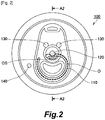
- the lid body 100 has a scribed score 110, a first rivet 120 for fixing the tab 200, and a pair of protruding sections 130. As indicated by dotted lines in Figs. 1 and 2 , an area bordered by the score 110 is a predetermined opening area O. An area depicted by an xx line in Fig. 2 is an opening start area OS. The opening start area OS is present in a vicinity of the first rivet 120.
- the pair of protruding sections 130 each having an approximately conical shape and formed in an area facing the tab 200 function as a rotation-stopping protrusion that restricts movement of the tab 200 in a rotation direction.
- the lid body 100 is provided with a second rivet 140 which rotatably supports the sliding member 300. The second rivet 140 may be provided by a riveting process to the lid body 100 or bonding a member to be the second rivet 140.
- the tab 200 has a through-hole 210 to be fixed by the first rivet 120, a leading end 220 on one side of the through-hole 210, and a rear end 230 on an opposite side to the leading end 220.
- the tab 200 has a U-shaped hole 240 which allows the tab 200 to easily deform when pulled up.
- the tab 200 has a finger hooking ring 250 on which one can hook a finger.
- the leading end 220 of the tab 200 is positioned inside the predetermined opening area O of the lid body 100.
- the rear end 230 of the tab 200 is positioned on an opposite side to the leading end 220 relative to a portion where the tab 200 is fixed to the lid body 100 (a portion where the first rivet 120 is provided).
- a user When opening the predetermined opening area O, a user normally hooks a finger on the rear end 230 or the finger hooking ring 250 and pulls up the tab 200.
- the sliding member 300 has an insertion section 310 which causes the rear end 230 of the tab 200 to move in a direction in which the rear end 230 separates from a surface of the lid body 100 and a through-hole 320 which allows the sliding member 300 to be rotatably supported by the second rivet 140 provided on the lid body 100.
- a tab-side end edge of the insertion section 310 has a thickness that allows the insertion section 310 to be inserted between the lid body 100 and the tab 200, and the sliding member 300 attached to the lid body 100 can be rotated around the second rivet 140. W hen the sliding member 300 is rotated clockwise in Fig. 1 , the sliding member 300 can slide (rotate) in a state where a part (the insertion section 310) of the sliding member 300 has penetrated into a gap between the lid body 100 and the tab 200.
- Fig. 8 is a plan view of the can lid representing a state where the sliding member 300 has been rotated clockwise by a prescribed angle from an initial position shown in Fig. 1 .
- Fig. 9 is a sectional view taken along A4-A4 in Fig. 8 .
- the insertion section 310 does not penetrate into a gap between the lid body 100 and the tab 200 (see Fig. 1 ).
- the sliding member 300 is configured such that rotating (sliding) the sliding member 300 causes the insertion section 310 to penetrate into the gap between the lid body 100 and the tab 200.
- the sliding member 300 While the sliding member 300 is caused to rotate (slide), after the insertion section 310 penetrates into the gap between the lid body 100 and the tab 200, the insertion section 310 comes into contact with the protruding section 130 and subsequently runs on the protruding section 130.
- the insertion section 310 is configured to run on a left-side protruding section 130 in Fig. 2 in the pair of protruding sections 130 shown in the drawing.
- the rear end 230 When the insertion section 310 runs on and is in sliding contact with the protruding section 130, the rear end 230 is caused to move in a direction in which the rear end 230 separates from the surface of the lid body 100 using the first rivet 120 as a fulcrum. This forms a gap between the rear end 230 and the lid body 100 (see Fig. 9 ).
- sliding the sliding member 300 of the can lid 10 according to the first embodiment from its initial position causes the rear end 230 of the tab 200 to move in a direction in which the rear end 230 separates from the surface of the lid body 100.
- This allows a user to insert a finger into a gap formed between the rear end 230 and the lid body 100 so that the tab 200 can be easily pulled up.
- making the sliding member 300 run on the protruding section 130 as a rotation-stopping protrusion for restricting movement of the tab 200 in the rotation direction causes the rear end of the tab 200 to move further in a direction in which the rear end separates from the surface of the lid body.
- the first embodiment includes a protruding section 130 that is in sliding contact with the sliding member 300 while the sliding member 300 is caused to slide from its initial position 130, and the protruding section 130 is formed on the lid body 100.
- a protruding section may be formed on the tab.
- the tab 200 of the first embodiment may have a protruding section on it that protrudes toward the lid body 100.
- Such protruding section may be configured so that the insertion section 310 penetrates between the protruding section (not shown) formed on the tab 200 and the lid body 100 after the insertion section 310 penetrates into the gap between the lid body 100 and the tab 200 while the sliding member 300 is caused to rotate (slide) from its initial position.
- the sliding member of the first embodiment may have a protruding section that is in sliding contact with the lid body or the tab while the sliding member is caused to slide from its initial position.
- the insertion section 310 of the sliding member 300 of the first embodiment may have a protruding section 310X as shown in Fig. 6 .
- the protruding section 310X may be provided on at least one of both surfaces of the insertion section 310. When the insertion section 310 penetrates into the gap between the lid body 100 and the tab 200, the protruding section 310X is in sliding contact with the lid body 100 or the tab 200 while the sliding member 300 is caused to rotate (slide) from its initial position.
- the insertion section 310 of the sliding member 300 of the first embodiment does not penetrate into the gap between the lid body 100 and the tab 200 in an initial state.
- the rear end 230 of the tab 200 moves by a certain distance in a direction in which the rear end 230 separates from the surface of the lid body 100 using the first rivet 120 as a fulcrum.
- the protruding section can be provided.
- the protruding section may be provided on any of the lid body 100, the tab 200, and the sliding member 300 as described above.
- the protruding section may be provided on two or more of the lid body 100, the tab 200, and the sliding member 300.
- the tab 200 may have a grasping surface without forming the finger hooking ring 250, and the grasping surface as a whole may be configured as a protruding section or a protruding section may be provided on a part of the grasping surface, the protruding section protruding toward the lid body 100 side.
- Various methods are possible for attaching the sliding member such as fixing by an adhesive for example and not limited to the above described method using the second rivet 140.
- Fig. 10 is a schematic sectional view of the sliding member according to the first modification and is a sectional view corresponding to a cross section taken along B-B in a diagram representing a case where the protruding section 310X shown in Fig. 6 is not provided.
- the sliding member according to the first modification is configured to be sloped toward a leading end side so that a height of the insertion section 310 in a thickness direction is greater on a left side in Fig. 10 than on a right side (i.e. H1 ⁇ H2 as shown in Fig. 10 ).
- Such a configuration makes it easier to cause the insertion section 310 to enter the gap between the lid body 100 and the tab 200 while the sliding member is caused to slide and enables the rear end 230 of the tab 200 to be gradually moved in a direction in which the rear end 230 separates from the surface of the lid body 100.
- the sloped configuration described above is realized by applying a bending process to an outer edge (on the leading end side) of the insertion section 310.
- the sloped configuration described above can also be realized by varying a thickness of a metal plate which is made of aluminum or the like and which constitutes the insertion section 310.
- a length in the insertion section 310 of the first modification from an end surface on the lid body side to an end surface on the tab side is configured to gradually change because of an inclined surface provided on an upper side as shown in Fig. 10 .
- a length in the insertion section from an end surface on the lid body side to an end surface on the tab side can be configured to change in stages by providing a stair-like step.
- the sliding member according to the first modification allows a large gap to be formed between the rear end 230 and the lid body 100 by sliding the sliding member. This allows a protruding section (the protruding section 130 or the like) described above to be omitted.
- a protruding section the protruding section 130 or the like
- the sliding member according to the first modification and a protruding section may be used in combination.
- Fig. 11 is an external view of the sliding member according to the second modification.
- a plan view of the sliding member In the left side of Fig. 11 is shown a plan view of the sliding member and in the right side the sliding member as viewed in a direction indicated by an arrow depicted in the plan view.
- a sliding member 300A according to the second modification has a projection 330 as an operating section for operating the sliding member 300A.
- the projection 330 allows a user to hook a finger on the projection 330, thereby the sliding member 300A can be easily caused to slide.
- FIG. 12 is an external view of the sliding member according to the third modification.
- a plan view of the sliding member In the left side of Fig. 12 is shown a plan view of the sliding member and in the right side the sliding member as viewed in a direction indicated by an arrow depicted in the plan view.
- a sliding member 300B according to the third modification has a recess 340 as an operating section for operating the sliding member 300B.
- the recess 340 allows a user to hook a finger on the recess 340, thereby the sliding member 300B can be easily caused to slide.
- Fig. 13 is an external view (a plan view) of the sliding member according to the fourth modification.
- a sliding member 300C according to the fourth modification has a hole 350 as an operating section for operating the sliding member 300C.
- the hole 350 allows a user to hook a finger on the hole 350, thereby the sliding member 300C can be easily caused to slide.
- Fig. 14 is an external view (a plan view) of the sliding member according to the fifth modification.
- a sliding member 300D according to the fifth modification has a non-slip structure section 360 as an operating section for operating the sliding member 300D.
- the non-slip structure section 360 has a structure which increases frictional resistance so as to prevent a finger from slipping.
- the non-slip structure section 360 which prevents a finger from slipping allows a user to easily cause the sliding member 300D to slide.
- An example non-slip structure section 360 may be a minute textured surface on a metallic sliding member 300D obtained through a blasting process.
- An example operating section is a projection (the second modification), a recess (the third modification), a hole (the fourth modification), or a non-slip structure section (the fifth modification) as described above, but not limited to them.
- the operating section may have at least any one of a projection, a recess, a hole, and a non-slip structure section, that is, the operating section may be configured by appropriately combining two or more of a projection, a recess, a hole, and a non-slip structure section.
- Fig. 15 is a plan view of a can lid according to a second embodiment.
- Fig. 15 shows main structures of the lid body and the tab only in a simplified manner.
- Fig. 15 shows a state where a sliding member 300E is at its initial position.
- the can lid 10 according to the second embodiment has a lid body 100, a tab 200 fixed to the lid body 100, and a sliding member 300E attached to the lid body 100.
- the sliding member 300E according to the second embodiment is rotatably supported by a second rivet 140E provided on the lid body 100. A position of the second rivet 140E differs from that of the first embodiment.
- the sliding member 300E is configured so as to penetrate into the gap between the lid body 100 and the tab 200 at an initial position of the sliding member 300E.
- the sliding member 300E has a rectangular plate-like member.
- the one end side of the sliding member 300E is rotatably supported by the second rivet 140E.
- a projection 330E as an operating section is formed on the other end side of the sliding member 300E.
- a portion near the projection 330E functions as an insertion section 310E.
- the sliding member 300E of the can lid 10 according to the second embodiment is caused to rotate (slide) in a direction indicated by an arrow R in Fig. 15
- the insertion section 310E is caused to come into contact with the protruding section 130E provided on the lid body 100 and subsequently run on and be in sliding contact with the protruding section 130E.
- the rear end 230 of the tab 200 moves in a direction in which the rear end 230 separates from the surface of the lid body 100 using the first rivet 120 as a fulcrum. This forms a gap between the rear end 230 and the lid body 100 in a similar manner to the first embodiment.
- a rotation-stopping protrusion of the second embodiment that restricts movement of the tab 200 in the rotation direction can be used as the protruding section 130E.
- a protruding section may be provided on the tab 200 instead of on the lid body 100 in the second embodiment as in the first embodiment.
- the insertion section 310E may be configured to have different heights in a thickness direction of the insertion section 310E between a leading end side and a rear end side in a slide direction as in the first modification shown in Fig. 10 .
- An operating section may not be limited to the projection 330E but various configurations may be adopted for the operating section as presented in the above described third to fifth modifications.
- the sliding member 300E of the second embodiment is rotatably supported by the second rivet 140E provided outside the finger hooking ring 250 in the tab 200 and on a right side in Fig. 15 .
- a position where the sliding member 300E is rotatably supported is not limited to the above described example. The position may be arranged inside the finger hooking ring 250 or arranged outside the finger hooking ring 250 and on an upper side in Fig. 15 . Further, a direction in which the sliding member 300E is caused to slide (rotate) from its initial position is not limited to the above described example.
- Fig. 16 shows a third embodiment.
- Fig. 16 is a plan view of a can lid according to the third embodiment.
- Fig. 16 shows main structures of the lid body and the tab only in a simplified manner.
- Fig. 16 shows a state where a sliding member 300F is at its initial position.
- the can lid 10 has a lid body 100, a tab 200 fixed to the lid body 100, and a sliding member 300F attached to the lid body 100.
- the sliding member 300F according to the third embodiment is rotatably supported by a first rivet 120 for fixing the tab 200.
- the first rivet 120 has a function of fixing the tab 200 as well as rotatably supporting the sliding member 300F.
- the sliding member 300F does not penetrate into the gap between the lid body 100 and the tab 200 at an initial position in a similar manner to the first embodiment.
- the sliding member 300F has an approximately fan-shaped plate-like member, an insertion section 310F formed on the leading end side in a rotation (slide) direction, and a projection 330F as an operating section formed on the rear end side.
- the sliding member 300F of the can lid 10 according to the third embodiment is caused to rotate (slide) in a direction indicated by an arrow R in Fig. 16
- the insertion section 310F is caused to come into contact with the protruding section 130F after penetrating into the gap between the lid body 100 and the tab 200 and subsequently run on and be in sliding contact with the protruding section 130F.
- the rear end 230 of the tab 200 moves in a direction in which the rear end 230 separates from the surface of the lid body 100 using the first rivet 120 as a fulcrum. This forms a gap between the rear end 230 and the lid body 100 in a similar manner to the first embodiment.
- a rotation-stopping protrusion of the third embodiment that restricts movement of the tab 200 in the rotation direction can be used as the protruding section 130F.
- a protruding section may be provided on the tab 200 or the sliding member 300F instead of on the lid body 100 in the third embodiment as in the first embodiment.
- the insertion section 310F may be configured to have different heights in a thickness direction of the insertion section 310F between a leading end side and a rear end side in a slide direction as in the first modification shown in Fig. 10 .
- An operating section may not be limited to the projection 330F but various configurations may be adopted for the operating section as in the above described third to fifth modifications.
- Fig. 17 shows a fourth embodiment.
- Fig. 17 is a plan view of a can lid according to the fourth embodiment. It should be noted that a sectional view of a part near a sliding member is also shown to the left of the plan view.
- Fig. 17 shows main structures of the lid body and the tab only in a simplified manner.
- Fig. 17 shows a state where a sliding member 300G is at its initial position.
- the can lid 10 according to the fourth embodiment has a lid body 100, a tab 200 fixed to the lid body 100 and a sliding member 300G.
- the sliding member 300G according to the fourth embodiment has a rectangular plate-like member and bent sections 371G and 372G provided at both ends in a direction perpendicular to a slide direction (a direction indicated by an arrow S in Fig. 17 ).
- a curling process is applied to linear sections 251 and 252 on both sides across the finger hooking ring 250.
- the sliding member 300G is attached so that the bent sections 371G and 372G described above are inserted into the linear sections 251 and 252 to which the curling process is performed in the tab 200.
- the fourth embodiment does not have a rivet for rotatably supporting the sliding member contrary to the respective embodiments described above.
- the sliding member 300G has a projection 330G at a center thereof.
- the sliding member 300G is arranged inside the gap between the lid body 100 and the tab 200.
- the sliding member 300G is arranged so that the projection 330G protrudes through the finger hooking ring 250 from a rear surface side (the lid body 100 side) toward a front surface side of the tab 200. Portions near both sides of the projection 330G respectively function as an insertion section 310G.
- the pair of insertion sections 310G are caused to come into contact with the pair of protruding sections 130G provided on the lid body 100 and subsequently run on and be in sliding contact with the protruding sections 130G.
- the rear end 230 of the tab 200 moves in a direction in which the rear end 230 separates from the surface of the lid body 100 using the first rivet 120 as a fulcrum. This forms a gap between the rear end 230 and the lid body 100 in a similar manner to the first embodiment.
- Both ends of the projection 330G in the sliding member 300G of the fourth embodiment is guided by both side surfaces of the finger hooking ring 250 provided in the tab 200, thereby the slide direction of the sliding member 300G is determined.
- a rotation-stopping protrusion of the fourth embodiment that restricts movement of the tab 200 in the rotation direction can be used as the protruding section 130G.
- a protruding section may be provided on the tab 200 instead of on the lid body 100 in the fourth embodiment as in the first embodiment.
- the insertion section 310G may be configured to have different heights in a thickness direction of the insertion section 310G between a leading end side and a rear end side in a slide direction as in the first modification shown in Fig. 10 .
- the sliding member 300G in the fourth embodiment is configured to slide in a vertical direction in Fig. 17
- the sliding member 300G may be configured to slide in a horizontal direction in Fig. 17 .
- a protruding section that is in sliding contact with the sliding member 300G while the sliding member 300G is caused to slide from an initial position may be provided on the lid body 100 or the tab 200.
- the sliding member 300G in the fourth embodiment is caused to slide downward in Fig. 17 from its initial position
- the sliding member 300G may be caused to slide upward in Fig. 17 from its initial position.
- a protruding section may be provided on an upper side in Fig. 17 with respect to the sliding member 300G.
- Fig. 18 shows a fifth embodiment.
- Fig. 18 is a plan view of a can lid according to the fifth embodiment.
- Fig. 18 shows main structures of the lid body and the tab only in a simplified manner.
- Fig. 18 shows a state where a sliding member 300H is at its initial position.
- the can lid 10 has a lid body 100, a tab 200 fixed to the lid body 100 and a sliding member 300H.
- the sliding member 300H according to the fifth embodiment has a pair of projections 330H as an operating section. Each of the pair of projections 330H is positioned near each of both sides of the tab 200.
- the lid body 100 has a pair of guiding projections 150 for determining a slide direction of the sliding member 300H.
- the fifth embodiment does not have a rivet for rotatably supporting the sliding member as in the fourth embodiment.
- the sliding member 300H has an approximately rectangular plate-like member and each of the projections 330H described above is provided near each of both ends of the sliding member 300H.
- the sliding member 300H is arranged inside the gap between the lid body 100 and the tab 200.
- the sliding member 300H is arranged so that both ends of the sliding member 300H are sandwiched between the pair of guiding projections 150.
- a portion of the sliding member 300H sandwiched between the lid body 100 and the tab 200 in an initial state functions as an insertion section 310H. Therefore, the insertion sections 310H are provided in pairs.
- a rotation-stopping protrusion of the fifth embodiment that restricts movement of the tab 200 in the rotation direction can be used as the protruding section 130H.
- a protruding section may be provided on the tab 200 instead of on the lid body 100 in the fifth embodiment as in the first embodiment.
- the insertion section 310H may be configured to have different heights in a thickness direction of the insertion section 310H between a leading end side and a rear end side in a slide direction as in the first modification shown in Fig. 10 .
- An operating section may not be limited to the projection 330H but various configurations may be adopted for the operating section as in the above described third to fifth modifications.
- the sliding member 300H of the fifth embodiment is arranged inside the gap between the lid body 100 and the tab 200 in an initial state.
- the sliding member 300H may be configured to be arranged outside the tab 200 (an upper side in Fig. 18 ) in the initial state and to enter the gap between the lid body 100 and the tab 200 while the sliding member 300H is caused to slide.
- Fig. 19 shows a sixth embodiment.
- Fig. 19 is a plan view of a can lid according to the sixth embodiment. It should be noted that a sectional view of a part near a sliding member and a side view are also shown to the right of the plan view.
- Fig. 19 shows main structures of the lid body and the tab only in a simplified manner.
- Fig. 19 shows a state where a sliding member 300I is at its initial position.
- the can lid 10 has a lid body 100, a tab 200 fixed to the lid body 100, and a sliding member 300I.
- the sixth embodiment does not have a rivet for rotatably supporting the sliding member as in the fourth and fifth embodiments.
- the sliding member 300I according to the sixth embodiment is attached to the tab 200 in a circumscribing manner around one linear section 251 of linear sections on both sides across the finger hooking ring 250.
- the sliding member 300I has a rectangular plate-like member and is attached to the linear section 251 by applying a bending process to the plate-like member. While the bending process of the sixth embodiment is performed so that leading ends of both ends of the plate-like member come into contact with each other, a gap may be formed between the leading ends. While the bending process of the sixth embodiment is applied to the sliding member 3001 from a front surface side toward a rear surface side (the lid body 100 side) of the tab 200, the bending process may be applied from the rear surface side toward the front surface side. According to the configuration described above, the sliding member 300I can be caused to slide along the linear section 251.
- a portion in the sliding member 300I of the sixth embodiment which is sandwiched between the lid body 100 and the tab 200 functions as an insertion section 3101.
- the sliding member 3001 of the can lid 10 according to the sixth embodiment configured as described above is caused to slide in a direction indicated by an arrow S in Fig. 19 , the insertion section 3101 is caused to come into contact with the protruding section 1301 provided on the lid body 100 and subsequently run on and be in sliding contact with the protruding section 1301.
- the rear end 230 of the tab 200 moves in a direction in which the rear end 230 separates from the surface of the lid body 100 using the first rivet 120 as a fulcrum. This forms a gap between the rear end 230 and the lid body 100 in a similar manner to the first embodiment.
- a rotation-stopping protrusion of the sixth embodiment that restricts movement of the tab 200 in the rotation direction can be used as the protruding section 130I. Since a range of motion of the sliding member 300I of the sixth embodiment is narrow, a plate-like section 380I which extends toward the protruding section 1301 as shown in the bottom-right side in Fig. 19 may be provided to ensure that the sliding member 3001 runs on the protruding section 1301.
- the sliding member 3001 of the sixth embodiment is attached to the linear section 251 which extends linearly.
- some tabs have a finger hooking ring with both sides thereof extending in curved lines. Even in this case, as long as a width of the portion extending in a curved line is constant, a similar sliding member to that of the sixth embodiment may be caused to slide and move, hence a similar configuration to the sixth embodiment may be adopted.
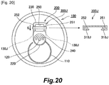
- Fig. 20 shows a seventh embodiment.
- Fig. 20 is a plan view of a can lid according to the seventh embodiment. It should be noted that a sectional view of a part near a sliding member is also shown to the right of the plan view.
- Fig. 20 shows main structures of the lid body and the tab only in a simplified manner.
- Fig. 20 shows a state where a sliding member 300J is at its initial position.
- the can lid 10 has a lid body 100, a tab 200 fixed to the lid body 100, and a sliding member 300J.
- the seventh embodiment does not have a rivet for rotatably supporting the sliding member as in the fourth to sixth embodiments.
- the sliding member 300J according to the seventh embodiment is attached to the tab 200 in a circumscribing manner around both linear sections 251 and 252 on both sides of the tab 200.
- the sliding member 300J has a rectangular plate-like member and is attached to the tab 200 by applying a bending process to the plate-like member. While the bending process of the seventh embodiment is performed so that a gap is formed between leading ends of both ends of the plate-like member, the leading ends may come into contact with each other. While the bending process of the seventh embodiment is applied to the sliding member 300J from a front surface side toward a rear surface side (the lid body 100 side) of the tab 200, the bending process may be applied from the rear surface side toward the front surface side. According to the configuration described above, the sliding member 300J can be caused to slide along the tab 200.
- a portion in the sliding member 300J of the seventh embodiment which is sandwiched between the lid body 100 and the tab 200 functions as an insertion section 310J.
- the sliding member 300J of the can lid 10 according to the seventh embodiment configured as described above is caused to slide in a direction indicated by an arrow S in Fig. 20
- the insertion section 310J is caused to come into contact with the protruding section 130J provided on the lid body 100 and subsequently run on and slide against the protruding section 130J.
- the rear end 230 of the tab 200 moves in a direction in which the rear end 230 separates from the surface of the lid body 100 using the first rivet 120 as a fulcrum. This form a gap between the rear end 230 and the lid body 100 in a similar manner to the first embodiment.
- the seventh embodiment can achieve similar effects to the first embodiment.
- a rotation-stopping protrusion of the seventh embodiment that restricts movement of the tab 200 in the rotation direction can be used as the protruding section 130J.
- a plate-like section which extends toward the protruding section 130J may be provided to ensure that the sliding member 300J runs on the protruding section 130J in the seventh embodiment as in the sixth embodiment.
- Fig. 21 shows an eighth embodiment.
- Fig. 21 is a plan view of a can lid according to the eighth embodiment. It should be noted that a side view (a view from a left side in the plan view) of a part near a sliding member is also shown below the plan view.
- Fig. 21 shows main structures of the lid body and the tab only in a simplified manner.
- Fig. 21 shows a state where a sliding member 300K is at its initial position.
- the can lid 10 has a lid body 100, a tab 200 fixed to the lid body 100 and a sliding member 300K.
- the sliding member 300K according to the eighth embodiment is rotatably provided with respect to the tab 200. More specifically, the sliding member 300K according to the eighth embodiment has a shaft 370K to be inserted to a through-hole 260 provided in the tab 200, an insertion section 310K fixed to the side of one end of the shaft 370K, and a knob 380K fixed to the side of another end of the shaft 370K. According to this configuration, the insertion section 310K can be caused to rotate (slide) by rotating the knob 380K in a direction indicated by an arrow R.
- the insertion section 310K of the can lid 10 When the insertion section 310K of the can lid 10 according to the eighth embodiment configured as described above is caused to slide by rotating the knob 380K, the insertion section 310K is caused to come into contact with the protruding section 130K provided on the lid body 100 and subsequently run on and be in sliding contact with the protruding section 130K.
- the rear end 230 of the tab 200 moves in a direction in which the rear end 230 separates from the surface of the lid body 100 using the first rivet 120 as a fulcrum. This forms a gap between the rear end 230 and the lid body 100 in a similar manner to the first embodiment.
- a protruding section may be provided on the tab 200 instead of on the lid body 100 in the eighth embodiment as in the first embodiment.
- the insertion section 310K may be configured to have different heights in a thickness direction of the insertion section 310K between a leading end side and a rear end side in a slide direction as in the first modification shown in Fig. 10 .
- the above described respective embodiments are examples which relate to a partially-open type can lid provided in a beverage can.
- the can lid according to the present invention may be applied to a full aperture-type can lid provided in food cans and the like.
Abstract
Description
- The present invention relates to a can lid provided in a can for storing a beverage or food.
- A can lid provided in a can for storing a beverage or food has a tab for opening the lid along a score scribed on the lid body. The tab is generally fixed to the lid body by a rivet. In order to form an opening in the lid body of such a can lid, one has to hook a finger on an end side of the tab and pull up the tab. Therefore, a tab of a can lid having no gap or a slight gap between a lid body and the tab sometimes cannot be easily pulled up.
-
- [PTL 1]
Japanese Patent Application Laid-open No.2001-315776 - [PTL 2]
Japanese Utility Model Application Laid-open No.H05-40133 - [PTL 3]
Japanese Patent Application Laid-open No.2015-42562 - An object of the present invention is to provide a can lid that enables a tab to be easily pulled up.
- In response to the above issue, the present invention adopts the following means.
- A can lid according to the present invention is a can lid that has
a lid body having a scribed score, and
a tab fixed to the lid body, wherein
the tab includes - a leading end positioned inside a predetermined opening area bordered by the score, and
- a rear end positioned on an opposite side to the leading end relative to a portion where the tab is fixed to the lid body, and
- According to the present invention, by causing the sliding member to slide, the rear end of the tab can be moved in a direction away from the surface of the lid body. This allows the tab to be more easily pulled up than a tab with the rear end thereof in contact with the surface of the lid body or a tab with the rear end thereof not in contact with the surface of the lid body but a slight gap formed between the rear end thereof and the surface of the lid body.
- A protruding section may be provided on at least one of the lid body and the tab, the protruding section being configured to be in sliding contact with the sliding member while the sliding member is caused to slide from the initial position.
- This configuration allows the rear end of the tab to be moved in a direction away from the surface of the lid body since the sliding member is in sliding contact with the protruding section while the sliding member is caused to slide from the initial position.
- A rotation-stopping protrusion may be provided in an area opposing the tab in the lid body, the rotation-stopping protrusion being configured to restrict movement of the tab in a rotation direction, and the rotation-stopping protrusion may have a protruding section that is configured to be in sliding contact with the sliding member while the sliding member is caused to slide from the initial position.
- This configuration enables the rotation-stopping protrusion that restricts movement of the tab in the rotation direction to have a function of moving the rear end of the tab in a direction away from the surface of the lid body.
- A protruding section may be provided on the sliding member, the protruding section being configured to be in sliding contact with the lid body or the tab while the sliding member is caused to slide from the initial position.
- Such protruding section formed on the sliding member in this manner even allows the rear end of the tab to be moved in a direction away from the surface of the lid body.
- A distance from an end surface on the lid body side to an end surface on the tab side in the insertion section may be shorter on a leading end side of the insertion section in a slide direction than on a rear end side.
- Such configuration even allows the rear end of the tab to be moved in a direction away from the surface of the lid body.
- The sliding member may have an operating section for operating the sliding member. In this case, the operating section may have at least any one of a projection, a recess, a hole, and a non-slip structure section.
- This configuration enables an operation for causing the sliding member to slide to be performed more easily.
- It should be noted that the respective components described above may be combined with each other to the greatest extent allowable.
- As described above, according to the present invention, a tab can be easily pulled up.
-
-
Fig. 1 is a plan view of a can lid according to a first embodiment. -
Fig. 2 is a plan view of a lid body according to the first embodiment. -
Fig. 3 is a schematic sectional view of the lid body according to the first embodiment. -
Fig. 4 is a plan view of a tab according to the first embodiment. -
Fig. 5 is a schematic sectional view of the tab according to the first embodiment. -
Fig. 6 is a plan view of a sliding member according to the first embodiment. -
Fig. 7 is a schematic sectional view of the can lid according to the first embodiment. -
Fig. 8 is a plan view of the can lid showing a situation in which the sliding member is operated according to the first embodiment. -
Fig. 9 is a schematic sectional view of the can lid showing a situation in which the sliding member is operated according to the first embodiment. -
Fig. 10 is a schematic sectional view of a sliding member according to a first modification. -
Fig. 11 is an external view of a sliding member according to a second modification. -
Fig. 12 is an external view of a sliding member according to a third modification. -
Fig. 13 is an external view of a sliding member according to a fourth modification. -
Fig. 14 is an external view of a sliding member according to a fifth modification. -
Fig. 15 is a plan view of a can lid according to a second embodiment. -
Fig. 16 is a plan view of a can lid according to a third embodiment. -
Fig. 17 is a plan view of a can lid according to a fourth embodiment. -
Fig. 18 is a plan view of a can lid according to a fifth embodiment. -
Fig. 19 is a plan view and a partial sectional view of a can lid according to a sixth embodiment. -
Fig. 20 is a plan view and a partial sectional view of a can lid according to a seventh embodiment. -
Fig. 21 is a plan view and a partial side view of a can lid according to an eighth embodiment. - Modes for implementing the present invention will now be exemplarily described in detail based on embodiments with reference to the drawings. It is to be understood that dimensions, materials, shapes, relative arrangements, and the like of components described in the embodiments are not intended to limit the scope of the present invention to the embodiments described below unless specifically stated to the contrary. A can lid in the present invention is provided in a can for storing a beverage or food. Can lids provided in beverage cans are commonly partially-open type can lids in which only a part of a lid body opens, while can lids provided in food cans are commonly full aperture type can lids in which approximately an entire area of a lid body opens. The following embodiments will be described using a partially-open type can lid provided in a beverage can as an example.
- A can lid according to a first embodiment of the present invention will be described with reference to
Figs. 1 to 9 .Fig. 1 is a plan view of the can lid according to the first embodiment.Fig. 2 is a plan view of a lid body according to the first embodiment.Fig. 3 is a schematic sectional view of the lid body according to the first embodiment and represents a sectional view taken along A2-A2 inFig. 2 .Fig. 4 is a plan view of a tab according to the first embodiment.Fig. 5 is a schematic sectional view of the tab according to the first embodiment and represents a sectional view taken along A3-A3 inFig. 4 .Fig. 6 is a plan view of a sliding member according to the first embodiment.Fig. 7 is a schematic sectional view of the can lid according to the first embodiment and represents a sectional view taken along A1-A1 inFig. 1 .Fig. 8 is a plan view of the can lid showing a situation in which the sliding member is operated according to the first embodiment.Fig. 9 is a schematic sectional view of the can lid showing a situation in which the sliding member is operated according to the first embodiment and represents a sectional view taken along A4-A4 inFig. 8 . - A configuration of a
can lid 10 according to the first embodiment will be described with reference toFigs. 1 to 7 . Thecan lid 10 according to the first embodiment has alid body 100, atab 200 fixed to thelid body 100, and a slidingmember 300 attached to thelid body 100. Thelid body 100, thetab 200, and the slidingmember 300 constituting thecan lid 10 are all made of a metal such as aluminum. - The
lid body 100 has a scribedscore 110, afirst rivet 120 for fixing thetab 200, and a pair of protrudingsections 130. As indicated by dotted lines inFigs. 1 and2 , an area bordered by thescore 110 is a predetermined opening area O. An area depicted by an xx line inFig. 2 is an opening start area OS. The opening start area OS is present in a vicinity of thefirst rivet 120. The pair of protrudingsections 130 each having an approximately conical shape and formed in an area facing thetab 200 function as a rotation-stopping protrusion that restricts movement of thetab 200 in a rotation direction. Thelid body 100 is provided with asecond rivet 140 which rotatably supports the slidingmember 300. Thesecond rivet 140 may be provided by a riveting process to thelid body 100 or bonding a member to be thesecond rivet 140. - The
tab 200 has a through-hole 210 to be fixed by thefirst rivet 120, aleading end 220 on one side of the through-hole 210, and arear end 230 on an opposite side to theleading end 220. Thetab 200 has aU-shaped hole 240 which allows thetab 200 to easily deform when pulled up. Thetab 200 has afinger hooking ring 250 on which one can hook a finger. In a state where thetab 200 is fixed to thelid body 100, theleading end 220 of thetab 200 is positioned inside the predetermined opening area O of thelid body 100. Therear end 230 of thetab 200 is positioned on an opposite side to theleading end 220 relative to a portion where thetab 200 is fixed to the lid body 100 (a portion where thefirst rivet 120 is provided). When opening the predetermined opening area O, a user normally hooks a finger on therear end 230 or thefinger hooking ring 250 and pulls up thetab 200. - The sliding
member 300 has aninsertion section 310 which causes therear end 230 of thetab 200 to move in a direction in which therear end 230 separates from a surface of thelid body 100 and a through-hole 320 which allows the slidingmember 300 to be rotatably supported by thesecond rivet 140 provided on thelid body 100. A tab-side end edge of theinsertion section 310 has a thickness that allows theinsertion section 310 to be inserted between thelid body 100 and thetab 200, and the slidingmember 300 attached to thelid body 100 can be rotated around thesecond rivet 140. W hen the slidingmember 300 is rotated clockwise inFig. 1 , the slidingmember 300 can slide (rotate) in a state where a part (the insertion section 310) of the slidingmember 300 has penetrated into a gap between thelid body 100 and thetab 200. - An operation of the tab that is caused by sliding the sliding
member 300 will be described with reference toFigs. 8 and9 .Fig. 8 is a plan view of the can lid representing a state where the slidingmember 300 has been rotated clockwise by a prescribed angle from an initial position shown inFig. 1 .Fig. 9 is a sectional view taken along A4-A4 inFig. 8 . In a state where the slidingmember 300 is at the initial position, theinsertion section 310 does not penetrate into a gap between thelid body 100 and the tab 200 (seeFig. 1 ). The slidingmember 300 is configured such that rotating (sliding) the slidingmember 300 causes theinsertion section 310 to penetrate into the gap between thelid body 100 and thetab 200. - While the sliding
member 300 is caused to rotate (slide), after theinsertion section 310 penetrates into the gap between thelid body 100 and thetab 200, theinsertion section 310 comes into contact with the protrudingsection 130 and subsequently runs on the protrudingsection 130. Theinsertion section 310 is configured to run on a left-side protruding section 130 inFig. 2 in the pair of protrudingsections 130 shown in the drawing. When theinsertion section 310 runs on and is in sliding contact with the protrudingsection 130, therear end 230 is caused to move in a direction in which therear end 230 separates from the surface of thelid body 100 using thefirst rivet 120 as a fulcrum. This forms a gap between therear end 230 and the lid body 100 (seeFig. 9 ). - As described above, sliding the sliding
member 300 of thecan lid 10 according to the first embodiment from its initial position causes therear end 230 of thetab 200 to move in a direction in which therear end 230 separates from the surface of thelid body 100. This allows a user to insert a finger into a gap formed between therear end 230 and thelid body 100 so that thetab 200 can be easily pulled up. In addition, making the slidingmember 300 run on the protrudingsection 130 as a rotation-stopping protrusion for restricting movement of thetab 200 in the rotation direction causes the rear end of thetab 200 to move further in a direction in which the rear end separates from the surface of the lid body. - The first embodiment includes a protruding
section 130 that is in sliding contact with the slidingmember 300 while the slidingmember 300 is caused to slide from itsinitial position 130, and the protrudingsection 130 is formed on thelid body 100. However, such a protruding section may be formed on the tab. For example, thetab 200 of the first embodiment may have a protruding section on it that protrudes toward thelid body 100. Such protruding section may be configured so that theinsertion section 310 penetrates between the protruding section (not shown) formed on thetab 200 and thelid body 100 after theinsertion section 310 penetrates into the gap between thelid body 100 and thetab 200 while the slidingmember 300 is caused to rotate (slide) from its initial position. This allows therear end 230 of thetab 200 to move in a direction in which therear end 230 separates from the surface of thelid body 100 using thefirst rivet 120 as a fulcrum when the slidingmember 300 is caused to slide in a similar manner to the first embodiment. - The sliding member of the first embodiment may have a protruding section that is in sliding contact with the lid body or the tab while the sliding member is caused to slide from its initial position. For example, the
insertion section 310 of the slidingmember 300 of the first embodiment may have a protrudingsection 310X as shown inFig. 6 . The protrudingsection 310X may be provided on at least one of both surfaces of theinsertion section 310. When theinsertion section 310 penetrates into the gap between thelid body 100 and thetab 200, the protrudingsection 310X is in sliding contact with thelid body 100 or thetab 200 while the slidingmember 300 is caused to rotate (slide) from its initial position. Providing the protrudingsection 310X on both surfaces of theinsertion section 310 causes each protrudingsection 310X to be in sliding contact with both thelid body 100 and thetab 200. This allows therear end 230 of thetab 200 to move in a direction in which therear end 230 separates from the surface of thelid body 100 using thefirst rivet 120 as a fulcrum when the slidingmember 300 is caused to slide in a similar manner to the first embodiment. - The
insertion section 310 of the slidingmember 300 of the first embodiment does not penetrate into the gap between thelid body 100 and thetab 200 in an initial state. When theinsertion section 310 penetrates into the gap between thelid body 100 and thetab 200 while the slidingmember 300 is caused to slide, therear end 230 of thetab 200 moves by a certain distance in a direction in which therear end 230 separates from the surface of thelid body 100 using thefirst rivet 120 as a fulcrum. In order to increase the gap between therear end 230 of thetab 200 and the surface of thelid body 100 to the greatest extent allowable, the protruding section can be provided. The protruding section may be provided on any of thelid body 100, thetab 200, and the slidingmember 300 as described above. The protruding section may be provided on two or more of thelid body 100, thetab 200, and the slidingmember 300. Thetab 200 may have a grasping surface without forming thefinger hooking ring 250, and the grasping surface as a whole may be configured as a protruding section or a protruding section may be provided on a part of the grasping surface, the protruding section protruding toward thelid body 100 side. Various methods are possible for attaching the sliding member such as fixing by an adhesive for example and not limited to the above described method using thesecond rivet 140. - Several modifications of a sliding member applicable to the can lid according to the first embodiment will now be described.
- A sliding member according to a first modification will be described with reference to
Fig. 10. Fig. 10 is a schematic sectional view of the sliding member according to the first modification and is a sectional view corresponding to a cross section taken along B-B in a diagram representing a case where the protrudingsection 310X shown inFig. 6 is not provided. The sliding member according to the first modification is configured to be sloped toward a leading end side so that a height of theinsertion section 310 in a thickness direction is greater on a left side inFig. 10 than on a right side (i.e. H1 < H2 as shown inFig. 10 ). Such a configuration makes it easier to cause theinsertion section 310 to enter the gap between thelid body 100 and thetab 200 while the sliding member is caused to slide and enables therear end 230 of thetab 200 to be gradually moved in a direction in which therear end 230 separates from the surface of thelid body 100. - In the first modification, the sloped configuration described above is realized by applying a bending process to an outer edge (on the leading end side) of the
insertion section 310. The sloped configuration described above can also be realized by varying a thickness of a metal plate which is made of aluminum or the like and which constitutes theinsertion section 310. A length in theinsertion section 310 of the first modification from an end surface on the lid body side to an end surface on the tab side is configured to gradually change because of an inclined surface provided on an upper side as shown inFig. 10 . A length in the insertion section from an end surface on the lid body side to an end surface on the tab side can be configured to change in stages by providing a stair-like step. - The sliding member according to the first modification allows a large gap to be formed between the
rear end 230 and thelid body 100 by sliding the sliding member. This allows a protruding section (the protrudingsection 130 or the like) described above to be omitted. Of course the sliding member according to the first modification and a protruding section may be used in combination. - A sliding member according to a second modification will be described with reference to
Fig. 11. Fig. 11 is an external view of the sliding member according to the second modification. In the left side ofFig. 11 is shown a plan view of the sliding member and in the right side the sliding member as viewed in a direction indicated by an arrow depicted in the plan view. - A sliding
member 300A according to the second modification has aprojection 330 as an operating section for operating the slidingmember 300A. Theprojection 330 allows a user to hook a finger on theprojection 330, thereby the slidingmember 300A can be easily caused to slide. - A sliding member according to a third modification will be described with reference to
Fig. 12. Fig. 12 is an external view of the sliding member according to the third modification. In the left side ofFig. 12 is shown a plan view of the sliding member and in the right side the sliding member as viewed in a direction indicated by an arrow depicted in the plan view. - A sliding
member 300B according to the third modification has arecess 340 as an operating section for operating the slidingmember 300B. Therecess 340 allows a user to hook a finger on therecess 340, thereby the slidingmember 300B can be easily caused to slide. - A sliding member according to a fourth modification will be described with reference to
Fig. 13. Fig. 13 is an external view (a plan view) of the sliding member according to the fourth modification. - A sliding
member 300C according to the fourth modification has ahole 350 as an operating section for operating the slidingmember 300C. Thehole 350 allows a user to hook a finger on thehole 350, thereby the slidingmember 300C can be easily caused to slide. - A sliding member according to a fifth modification will be described with reference to
Fig. 14. Fig. 14 is an external view (a plan view) of the sliding member according to the fifth modification. - A sliding
member 300D according to the fifth modification has anon-slip structure section 360 as an operating section for operating the slidingmember 300D. Thenon-slip structure section 360 has a structure which increases frictional resistance so as to prevent a finger from slipping. Thenon-slip structure section 360 which prevents a finger from slipping allows a user to easily cause the slidingmember 300D to slide. An examplenon-slip structure section 360 may be a minute textured surface on a metallic slidingmember 300D obtained through a blasting process. - An example operating section is a projection (the second modification), a recess (the third modification), a hole (the fourth modification), or a non-slip structure section (the fifth modification) as described above, but not limited to them. The operating section may have at least any one of a projection, a recess, a hole, and a non-slip structure section, that is, the operating section may be configured by appropriately combining two or more of a projection, a recess, a hole, and a non-slip structure section.
- Hereinafter, configurations in which the sliding member is configured differently from the first embodiment described above will be presented in second to eighth embodiments. Since other configurations and effects of such as the lid body and the tab are approximately the same as those of the first embodiment, the same components will be denoted by the same reference characters and a description thereof will be omitted.
-
Fig. 15 is a plan view of a can lid according to a second embodiment.Fig. 15 shows main structures of the lid body and the tab only in a simplified manner.Fig. 15 shows a state where a slidingmember 300E is at its initial position. - As shown in
Fig. 15 , thecan lid 10 according to the second embodiment has alid body 100, atab 200 fixed to thelid body 100, and a slidingmember 300E attached to thelid body 100. The slidingmember 300E according to the second embodiment is rotatably supported by asecond rivet 140E provided on thelid body 100. A position of thesecond rivet 140E differs from that of the first embodiment. - The sliding
member 300E is configured so as to penetrate into the gap between thelid body 100 and thetab 200 at an initial position of the slidingmember 300E. The slidingmember 300E has a rectangular plate-like member. The one end side of the slidingmember 300E is rotatably supported by thesecond rivet 140E. Aprojection 330E as an operating section is formed on the other end side of the slidingmember 300E. A portion near theprojection 330E functions as aninsertion section 310E. - When the sliding
member 300E of thecan lid 10 according to the second embodiment is caused to rotate (slide) in a direction indicated by an arrow R inFig. 15 , theinsertion section 310E is caused to come into contact with the protrudingsection 130E provided on thelid body 100 and subsequently run on and be in sliding contact with the protrudingsection 130E. Thus, therear end 230 of thetab 200 moves in a direction in which therear end 230 separates from the surface of thelid body 100 using thefirst rivet 120 as a fulcrum. This forms a gap between therear end 230 and thelid body 100 in a similar manner to the first embodiment. - As described above, the second embodiment can achieve similar effects to the first embodiment. A rotation-stopping protrusion of the second embodiment that restricts movement of the
tab 200 in the rotation direction can be used as the protrudingsection 130E. A protruding section may be provided on thetab 200 instead of on thelid body 100 in the second embodiment as in the first embodiment. Theinsertion section 310E may be configured to have different heights in a thickness direction of theinsertion section 310E between a leading end side and a rear end side in a slide direction as in the first modification shown inFig. 10 . An operating section may not be limited to theprojection 330E but various configurations may be adopted for the operating section as presented in the above described third to fifth modifications. - The sliding
member 300E of the second embodiment is rotatably supported by thesecond rivet 140E provided outside thefinger hooking ring 250 in thetab 200 and on a right side inFig. 15 . A position where the slidingmember 300E is rotatably supported is not limited to the above described example. The position may be arranged inside thefinger hooking ring 250 or arranged outside thefinger hooking ring 250 and on an upper side inFig. 15 . Further, a direction in which the slidingmember 300E is caused to slide (rotate) from its initial position is not limited to the above described example. -
Fig. 16 shows a third embodiment.Fig. 16 is a plan view of a can lid according to the third embodiment.Fig. 16 shows main structures of the lid body and the tab only in a simplified manner.Fig. 16 shows a state where a slidingmember 300F is at its initial position. - As shown in
Fig. 16 , thecan lid 10 according to the third embodiment has alid body 100, atab 200 fixed to thelid body 100, and a slidingmember 300F attached to thelid body 100. The slidingmember 300F according to the third embodiment is rotatably supported by afirst rivet 120 for fixing thetab 200. In other words, thefirst rivet 120 has a function of fixing thetab 200 as well as rotatably supporting the slidingmember 300F. - The sliding
member 300F does not penetrate into the gap between thelid body 100 and thetab 200 at an initial position in a similar manner to the first embodiment. The slidingmember 300F has an approximately fan-shaped plate-like member, aninsertion section 310F formed on the leading end side in a rotation (slide) direction, and aprojection 330F as an operating section formed on the rear end side. - When the sliding
member 300F of thecan lid 10 according to the third embodiment is caused to rotate (slide) in a direction indicated by an arrow R inFig. 16 , theinsertion section 310F is caused to come into contact with the protrudingsection 130F after penetrating into the gap between thelid body 100 and thetab 200 and subsequently run on and be in sliding contact with the protrudingsection 130F. Thus, therear end 230 of thetab 200 moves in a direction in which therear end 230 separates from the surface of thelid body 100 using thefirst rivet 120 as a fulcrum. This forms a gap between therear end 230 and thelid body 100 in a similar manner to the first embodiment. - As described above, the third embodiment can achieve similar effects to the first embodiment. A rotation-stopping protrusion of the third embodiment that restricts movement of the
tab 200 in the rotation direction can be used as the protrudingsection 130F. A protruding section may be provided on thetab 200 or the slidingmember 300F instead of on thelid body 100 in the third embodiment as in the first embodiment. Theinsertion section 310F may be configured to have different heights in a thickness direction of theinsertion section 310F between a leading end side and a rear end side in a slide direction as in the first modification shown inFig. 10 . An operating section may not be limited to theprojection 330F but various configurations may be adopted for the operating section as in the above described third to fifth modifications. -
Fig. 17 shows a fourth embodiment.Fig. 17 is a plan view of a can lid according to the fourth embodiment. It should be noted that a sectional view of a part near a sliding member is also shown to the left of the plan view.Fig. 17 shows main structures of the lid body and the tab only in a simplified manner.Fig. 17 shows a state where a slidingmember 300G is at its initial position. - As shown in
Fig. 17 , thecan lid 10 according to the fourth embodiment has alid body 100, atab 200 fixed to thelid body 100 and a slidingmember 300G. The slidingmember 300G according to the fourth embodiment has a rectangular plate-like member andbent sections Fig. 17 ). In thetab 200, a curling process is applied tolinear sections finger hooking ring 250. The slidingmember 300G is attached so that thebent sections linear sections tab 200. Thus, the fourth embodiment does not have a rivet for rotatably supporting the sliding member contrary to the respective embodiments described above. - The sliding
member 300G according to the fourth embodiment has aprojection 330G at a center thereof. The slidingmember 300G is arranged inside the gap between thelid body 100 and thetab 200. The slidingmember 300G is arranged so that theprojection 330G protrudes through thefinger hooking ring 250 from a rear surface side (thelid body 100 side) toward a front surface side of thetab 200. Portions near both sides of theprojection 330G respectively function as aninsertion section 310G. - When the sliding
member 300G of thecan lid 10 according to the fourth embodiment configured as described above is caused to slide in a direction indicated by an arrow S inFig. 17 , the pair ofinsertion sections 310G are caused to come into contact with the pair of protrudingsections 130G provided on thelid body 100 and subsequently run on and be in sliding contact with the protrudingsections 130G. Thus, therear end 230 of thetab 200 moves in a direction in which therear end 230 separates from the surface of thelid body 100 using thefirst rivet 120 as a fulcrum. This forms a gap between therear end 230 and thelid body 100 in a similar manner to the first embodiment. Both ends of theprojection 330G in the slidingmember 300G of the fourth embodiment is guided by both side surfaces of thefinger hooking ring 250 provided in thetab 200, thereby the slide direction of the slidingmember 300G is determined. - As described above, the fourth embodiment can achieve similar effects to the first embodiment. A rotation-stopping protrusion of the fourth embodiment that restricts movement of the
tab 200 in the rotation direction can be used as the protrudingsection 130G. A protruding section may be provided on thetab 200 instead of on thelid body 100 in the fourth embodiment as in the first embodiment. Theinsertion section 310G may be configured to have different heights in a thickness direction of theinsertion section 310G between a leading end side and a rear end side in a slide direction as in the first modification shown inFig. 10 . - While the sliding
member 300G in the fourth embodiment is configured to slide in a vertical direction inFig. 17 , the slidingmember 300G may be configured to slide in a horizontal direction inFig. 17 . In this case, a protruding section that is in sliding contact with the slidingmember 300G while the slidingmember 300G is caused to slide from an initial position may be provided on thelid body 100 or thetab 200. While the slidingmember 300G in the fourth embodiment is caused to slide downward inFig. 17 from its initial position, the slidingmember 300G may be caused to slide upward inFig. 17 from its initial position. In this case, a protruding section may be provided on an upper side inFig. 17 with respect to the slidingmember 300G. -
Fig. 18 shows a fifth embodiment.Fig. 18 is a plan view of a can lid according to the fifth embodiment.Fig. 18 shows main structures of the lid body and the tab only in a simplified manner.Fig. 18 shows a state where a slidingmember 300H is at its initial position. - As shown in
Fig. 18 , thecan lid 10 according to the fifth embodiment has alid body 100, atab 200 fixed to thelid body 100 and a slidingmember 300H. The slidingmember 300H according to the fifth embodiment has a pair ofprojections 330H as an operating section. Each of the pair ofprojections 330H is positioned near each of both sides of thetab 200. Thelid body 100 has a pair of guidingprojections 150 for determining a slide direction of the slidingmember 300H. The fifth embodiment does not have a rivet for rotatably supporting the sliding member as in the fourth embodiment. - The sliding
member 300H according to the fifth embodiment has an approximately rectangular plate-like member and each of theprojections 330H described above is provided near each of both ends of the slidingmember 300H. The slidingmember 300H is arranged inside the gap between thelid body 100 and thetab 200. The slidingmember 300H is arranged so that both ends of the slidingmember 300H are sandwiched between the pair of guidingprojections 150. A portion of the slidingmember 300H sandwiched between thelid body 100 and thetab 200 in an initial state functions as aninsertion section 310H. Therefore, theinsertion sections 310H are provided in pairs. - When the sliding
member 300H of thecan lid 10 according to the fifth embodiment configured as described above is caused to slide in a direction indicated by an arrow S inFig. 18 , the pair ofinsertion sections 310H are caused to come into contact with the pair of protrudingsections 130H provided on thelid body 100 and subsequently run on and be in sliding contact with the protrudingsections 130H. Thus, therear end 230 of thetab 200 moves in a direction in which therear end 230 separates from the surface of thelid body 100 using thefirst rivet 120 as a fulcrum. This forms a gap between therear end 230 and thelid body 100 in a similar manner to the first embodiment. Both ends of the slidingmember 300H of the fifth embodiment are guided by the pair of guidingprojections 150 provided on thelid body 100, thereby the slide direction of the slidingmember 300H is determined. - As described above, the fifth embodiment can achieve similar effects to the first embodiment. A rotation-stopping protrusion of the fifth embodiment that restricts movement of the
tab 200 in the rotation direction can be used as the protrudingsection 130H. A protruding section may be provided on thetab 200 instead of on thelid body 100 in the fifth embodiment as in the first embodiment. Theinsertion section 310H may be configured to have different heights in a thickness direction of theinsertion section 310H between a leading end side and a rear end side in a slide direction as in the first modification shown inFig. 10 . An operating section may not be limited to theprojection 330H but various configurations may be adopted for the operating section as in the above described third to fifth modifications. The slidingmember 300H of the fifth embodiment is arranged inside the gap between thelid body 100 and thetab 200 in an initial state. The slidingmember 300H may be configured to be arranged outside the tab 200 (an upper side inFig. 18 ) in the initial state and to enter the gap between thelid body 100 and thetab 200 while the slidingmember 300H is caused to slide. -
Fig. 19 shows a sixth embodiment.Fig. 19 is a plan view of a can lid according to the sixth embodiment. It should be noted that a sectional view of a part near a sliding member and a side view are also shown to the right of the plan view.Fig. 19 shows main structures of the lid body and the tab only in a simplified manner.Fig. 19 shows a state where a sliding member 300I is at its initial position. - As shown in
Fig. 19 , thecan lid 10 according to the sixth embodiment has alid body 100, atab 200 fixed to thelid body 100, and a sliding member 300I. The sixth embodiment does not have a rivet for rotatably supporting the sliding member as in the fourth and fifth embodiments. - The sliding member 300I according to the sixth embodiment is attached to the
tab 200 in a circumscribing manner around onelinear section 251 of linear sections on both sides across thefinger hooking ring 250. The sliding member 300I has a rectangular plate-like member and is attached to thelinear section 251 by applying a bending process to the plate-like member. While the bending process of the sixth embodiment is performed so that leading ends of both ends of the plate-like member come into contact with each other, a gap may be formed between the leading ends. While the bending process of the sixth embodiment is applied to the slidingmember 3001 from a front surface side toward a rear surface side (thelid body 100 side) of thetab 200, the bending process may be applied from the rear surface side toward the front surface side. According to the configuration described above, the sliding member 300I can be caused to slide along thelinear section 251. - A portion in the sliding member 300I of the sixth embodiment which is sandwiched between the
lid body 100 and thetab 200 functions as an insertion section 3101. - When the sliding
member 3001 of thecan lid 10 according to the sixth embodiment configured as described above is caused to slide in a direction indicated by an arrow S inFig. 19 , the insertion section 3101 is caused to come into contact with the protrudingsection 1301 provided on thelid body 100 and subsequently run on and be in sliding contact with the protrudingsection 1301. Thus, therear end 230 of thetab 200 moves in a direction in which therear end 230 separates from the surface of thelid body 100 using thefirst rivet 120 as a fulcrum. This forms a gap between therear end 230 and thelid body 100 in a similar manner to the first embodiment. - As described above, the sixth embodiment can achieve similar effects to the first embodiment. A rotation-stopping protrusion of the sixth embodiment that restricts movement of the
tab 200 in the rotation direction can be used as the protruding section 130I. Since a range of motion of the sliding member 300I of the sixth embodiment is narrow, a plate-like section 380I which extends toward the protrudingsection 1301 as shown in the bottom-right side inFig. 19 may be provided to ensure that the slidingmember 3001 runs on the protrudingsection 1301. The slidingmember 3001 of the sixth embodiment is attached to thelinear section 251 which extends linearly. However, some tabs have a finger hooking ring with both sides thereof extending in curved lines. Even in this case, as long as a width of the portion extending in a curved line is constant, a similar sliding member to that of the sixth embodiment may be caused to slide and move, hence a similar configuration to the sixth embodiment may be adopted. -
Fig. 20 shows a seventh embodiment.Fig. 20 is a plan view of a can lid according to the seventh embodiment. It should be noted that a sectional view of a part near a sliding member is also shown to the right of the plan view.Fig. 20 shows main structures of the lid body and the tab only in a simplified manner.Fig. 20 shows a state where a slidingmember 300J is at its initial position. - As shown in
Fig. 20 , thecan lid 10 according to the seventh embodiment has alid body 100, atab 200 fixed to thelid body 100, and a slidingmember 300J. The seventh embodiment does not have a rivet for rotatably supporting the sliding member as in the fourth to sixth embodiments. - The sliding
member 300J according to the seventh embodiment is attached to thetab 200 in a circumscribing manner around bothlinear sections tab 200. The slidingmember 300J has a rectangular plate-like member and is attached to thetab 200 by applying a bending process to the plate-like member. While the bending process of the seventh embodiment is performed so that a gap is formed between leading ends of both ends of the plate-like member, the leading ends may come into contact with each other. While the bending process of the seventh embodiment is applied to the slidingmember 300J from a front surface side toward a rear surface side (thelid body 100 side) of thetab 200, the bending process may be applied from the rear surface side toward the front surface side. According to the configuration described above, the slidingmember 300J can be caused to slide along thetab 200. - A portion in the sliding
member 300J of the seventh embodiment which is sandwiched between thelid body 100 and thetab 200 functions as aninsertion section 310J. - When the sliding
member 300J of thecan lid 10 according to the seventh embodiment configured as described above is caused to slide in a direction indicated by an arrow S inFig. 20 , theinsertion section 310J is caused to come into contact with the protrudingsection 130J provided on thelid body 100 and subsequently run on and slide against the protrudingsection 130J. Thus, therear end 230 of thetab 200 moves in a direction in which therear end 230 separates from the surface of thelid body 100 using thefirst rivet 120 as a fulcrum. This form a gap between therear end 230 and thelid body 100 in a similar manner to the first embodiment. - As described above, the seventh embodiment can achieve similar effects to the first embodiment. A rotation-stopping protrusion of the seventh embodiment that restricts movement of the
tab 200 in the rotation direction can be used as the protrudingsection 130J. A plate-like section which extends toward the protrudingsection 130J may be provided to ensure that the slidingmember 300J runs on the protrudingsection 130J in the seventh embodiment as in the sixth embodiment. -
Fig. 21 shows an eighth embodiment.Fig. 21 is a plan view of a can lid according to the eighth embodiment. It should be noted that a side view (a view from a left side in the plan view) of a part near a sliding member is also shown below the plan view.Fig. 21 shows main structures of the lid body and the tab only in a simplified manner.Fig. 21 shows a state where a slidingmember 300K is at its initial position. - As shown in
Fig. 21 , thecan lid 10 according to the eighth embodiment has alid body 100, atab 200 fixed to thelid body 100 and a slidingmember 300K. - The sliding
member 300K according to the eighth embodiment is rotatably provided with respect to thetab 200. More specifically, the slidingmember 300K according to the eighth embodiment has ashaft 370K to be inserted to a through-hole 260 provided in thetab 200, aninsertion section 310K fixed to the side of one end of theshaft 370K, and aknob 380K fixed to the side of another end of theshaft 370K. According to this configuration, theinsertion section 310K can be caused to rotate (slide) by rotating theknob 380K in a direction indicated by an arrow R. - When the
insertion section 310K of thecan lid 10 according to the eighth embodiment configured as described above is caused to slide by rotating theknob 380K, theinsertion section 310K is caused to come into contact with the protrudingsection 130K provided on thelid body 100 and subsequently run on and be in sliding contact with the protrudingsection 130K. Thus, therear end 230 of thetab 200 moves in a direction in which therear end 230 separates from the surface of thelid body 100 using thefirst rivet 120 as a fulcrum. This forms a gap between therear end 230 and thelid body 100 in a similar manner to the first embodiment. - As described above, the eighth embodiment can achieve similar effects to the first embodiment. A protruding section may be provided on the
tab 200 instead of on thelid body 100 in the eighth embodiment as in the first embodiment. Theinsertion section 310K may be configured to have different heights in a thickness direction of theinsertion section 310K between a leading end side and a rear end side in a slide direction as in the first modification shown inFig. 10 . - The above described respective embodiments are examples which relate to a partially-open type can lid provided in a beverage can. However, the can lid according to the present invention may be applied to a full aperture-type can lid provided in food cans and the like.
-
- 10
- Can lid
- 100
- Lid body
- 110
- Score
- 120
- First rivet
- 130, 130E, 130F, 130G, 130H, 130I, 130J, 130K
- Protruding section
- 140, 140E
- Second rivet
- 150
- Guiding projection
- 200
- Tab
- 210
- Through-hole
- 220
- Leading end
- 230
- Rear end
- 240
- U-shaped hole
- 250
- Finger hooking ring
- 251, 252
- Linear section
- 260
- Through-hole
- 300, 300A, 300B, 300C, 300D, 300E, 300F, 300G, 300H, 3001, 300J, 300K
- Sliding member
- 310, 310E, 310F, 310G, 310H, 310I, 310J, 310K
- Insertion section
- 310X
- Protruding section
- 320
- Through-hole
- 330, 330E, 330F, 330G, 330H
- Projection
- 340
- Recess
- 350
- Hole
- 360
- Non-slip structure section
- 371G, 372G
- Bent section
- 370K
- Shaft
- 380I
- Plate-like section
- 380K
- Knob
- O
- Predetermined opening area
- OS
- Opening start area
Claims (7)
- A can lid comprising:a lid body having a scribed score; anda tab fixed to the lid body, whereinthe tab includesa leading end positioned inside a predetermined opening area bordered by the score, anda rear end positioned on an opposite side to the leading end relative to a portion where the tab is fixed to the lid body, andthe can lid has a sliding member which is configured to slide in a state where a part thereof penetrates into a gap between the lid body and the tab, the sliding member having an insertion section which is configured to move the rear end of the tab in a direction away from a surface of the lid body when the sliding member is caused to slide from an initial position.
- The can lid according to claim 1, wherein a protruding section is provided on at least one of the lid body and the tab, the protruding section being configured to be in sliding contact with the sliding member while the sliding member is caused to slide from the initial position.
- The can lid according to claim 1, wherein a rotation-stopping protrusion is provided in an area opposing the tab in the lid body, the rotation-stopping protrusion being configured to restrict movement of the tab in a rotation direction, and the rotation-stopping protrusion has a protruding section that is configured to be in sliding contact with the sliding member while the sliding member is caused to slide from the initial position.
- The can lid according to claim 1, 2, or 3, wherein a protruding section is provided on the sliding member, the protruding section being configured to be in sliding contact with the lid body or the tab while the sliding member is caused to slide from the initial position.
- The can lid according to any one of claims 1 to 4, wherein a distance from an end surface on the lid body side to an end surface on the tab side in the insertion section is shorter on a leading end side of the insertion section in a slide direction than on a rear end side.
- The can lid according to any one of claims 1 to 5, wherein the sliding member has an operating section for operating the sliding member.
- The can lid according to claim 6, wherein the operating section has at least any one of a projection, a recess, a hole, and a non-slip structure section.
Applications Claiming Priority (2)
| Application Number | Priority Date | Filing Date | Title |
|---|---|---|---|
| JP2016161975A JP6972520B2 (en) | 2016-08-22 | 2016-08-22 | Can lid |
| PCT/JP2017/028073 WO2018037865A1 (en) | 2016-08-22 | 2017-08-02 | Can lid |
Publications (2)
| Publication Number | Publication Date |
|---|---|
| EP3502001A1 true EP3502001A1 (en) | 2019-06-26 |
| EP3502001A4 EP3502001A4 (en) | 2020-04-29 |
Family
ID=61245703
Family Applications (1)
| Application Number | Title | Priority Date | Filing Date |
|---|---|---|---|
| EP17843351.2A Withdrawn EP3502001A4 (en) | 2016-08-22 | 2017-08-02 | Can lid |
Country Status (6)
| Country | Link |
|---|---|
| US (1) | US20190177034A1 (en) |
| EP (1) | EP3502001A4 (en) |
| JP (1) | JP6972520B2 (en) |
| KR (1) | KR102164757B1 (en) |
| CN (1) | CN109789946A (en) |
| WO (1) | WO2018037865A1 (en) |
Families Citing this family (2)
| Publication number | Priority date | Publication date | Assignee | Title |
|---|---|---|---|---|
| KR102195102B1 (en) * | 2020-02-12 | 2020-12-24 | 서경배 | Can end of food and beverage container |
| WO2021162410A1 (en) * | 2020-02-12 | 2021-08-19 | 서경배 | Cover for food and beverage container |
Family Cites Families (22)
| Publication number | Priority date | Publication date | Assignee | Title |
|---|---|---|---|---|
| US3250425A (en) * | 1964-02-17 | 1966-05-10 | Continental Can Co | Rotatable pull tab to break scored tear strip |
| US4887712A (en) * | 1988-06-15 | 1989-12-19 | Wells Robert A | Reclosable self-opening can end |
| US4872597A (en) * | 1988-10-13 | 1989-10-10 | Hisao Hanafusa | Beverage container with dual dispensing tabs |
| US5248053A (en) * | 1990-02-02 | 1993-09-28 | Lundgren James F | Operating lever for beverage container lever operated opener |
| JPH0540133A (en) | 1991-08-06 | 1993-02-19 | Fujitsu Ltd | Signal-waveform measuring apparatus |
| JP2587404Y2 (en) | 1991-10-29 | 1998-12-16 | 北海製罐株式会社 | Easy open can lid |
| US5224618A (en) * | 1992-06-22 | 1993-07-06 | Garbiso Michael J | Easy opening tab for container |
| JPH08580U (en) * | 1993-08-16 | 1996-04-02 | 勝彦 小玉 | Can lid opening device |
| JP3363261B2 (en) * | 1994-06-27 | 2003-01-08 | 松下電工株式会社 | Sphygmomanometer |
| JPH0826275A (en) * | 1994-07-11 | 1996-01-30 | Mitsubishi Materials Corp | Can lid and manufacture therefor |
| JP3027910U (en) * | 1996-02-13 | 1996-08-20 | 日本プライズ産業株式会社 | Beverage cans and beverage containers |
| DE29812116U1 (en) * | 1998-07-10 | 1998-11-19 | Schley Alexander | Resealable beverage can lid |
| JP2000185736A (en) * | 1998-10-14 | 2000-07-04 | Kazunori Mototsu | Can container with pull-tab |
| JP2001315776A (en) * | 2000-05-09 | 2001-11-13 | Tetsuo Okuyama | Stay on tab can cover and opening member used for the same |
| CN2454295Y (en) * | 2000-11-02 | 2001-10-17 | 翟宏国 | Rotary pry-pull opening type sealing cover |
| KR20040008368A (en) * | 2002-07-18 | 2004-01-31 | 박창복 | Can for beverage |
| KR200335552Y1 (en) * | 2003-07-08 | 2003-12-11 | 윤만석 | opener structure for beverage can |
| JP4466944B2 (en) * | 2003-09-03 | 2010-05-26 | 大和製罐株式会社 | Easy-to-open can lid |
| US7631777B1 (en) * | 2007-09-10 | 2009-12-15 | Bukowski Bryan A | Can and bottle covers |
| CN203143168U (en) * | 2013-04-11 | 2013-08-21 | 滁州学院 | Improved pop can cap |
| JP2015042562A (en) | 2014-06-20 | 2015-03-05 | 光広 今村 | Beverage can and method for opening beverage can |
| CN105416765A (en) * | 2015-11-27 | 2016-03-23 | 苏州市职业大学 | Ring-pull can lid |
-
2016
- 2016-08-22 JP JP2016161975A patent/JP6972520B2/en active Active
-
2017
- 2017-08-02 EP EP17843351.2A patent/EP3502001A4/en not_active Withdrawn
- 2017-08-02 US US16/327,356 patent/US20190177034A1/en not_active Abandoned
- 2017-08-02 KR KR1020197008001A patent/KR102164757B1/en active IP Right Grant
- 2017-08-02 WO PCT/JP2017/028073 patent/WO2018037865A1/en active Application Filing
- 2017-08-02 CN CN201780051353.6A patent/CN109789946A/en active Pending
Also Published As
| Publication number | Publication date |
|---|---|
| EP3502001A4 (en) | 2020-04-29 |
| KR20190040042A (en) | 2019-04-16 |
| KR102164757B1 (en) | 2020-10-13 |
| WO2018037865A1 (en) | 2018-03-01 |
| CN109789946A (en) | 2019-05-21 |
| US20190177034A1 (en) | 2019-06-13 |
| JP2018030590A (en) | 2018-03-01 |
| JP6972520B2 (en) | 2021-11-24 |
Similar Documents
| Publication | Publication Date | Title |
|---|---|---|
| EP2822417B1 (en) | Locking double carabineer | |
| KR101728847B1 (en) | Push-in fastener assembly | |
| EP3502001A1 (en) | Can lid | |
| US9982700B2 (en) | Fastener | |
| US9341210B2 (en) | Fastener | |
| EP2489590A1 (en) | Wing panel and aircraft main wing | |
| JPWO2015064525A1 (en) | Stop | |
| US7646592B2 (en) | Expansion card retention device and methods thereof | |
| KR20200042524A (en) | Clamps for trinkets, assembly sets and trinkets for trinkets | |
| US20160235224A1 (en) | Heavy-Duty Plastic Picture Hanger Having Dual-Hooks And Hook-Above-Nail Arrangements | |
| US20120227226A1 (en) | Clip | |
| CN101467223B (en) | Device for absorption of noise | |
| JP6196096B2 (en) | Clip mounting seat for interior parts or exterior parts | |
| EP2881600A1 (en) | Fixture | |
| EP3364051B1 (en) | A method for mounting a sheet like member onto a mounted member by utilizing a fastening device and mounting structure | |
| JP7348391B2 (en) | Fastener | |
| JP2020034024A (en) | Fastener | |
| WO2012157614A1 (en) | Hole plug | |
| JP6115376B2 (en) | Panel fixing structure and automatic transaction device | |
| JP6783020B2 (en) | Fender and bumper mounting structure | |
| US9808053B2 (en) | Magnetic clasp for jewelry | |
| JP2011027214A (en) | Fastener | |
| JP5859919B2 (en) | Clip and fastener with the clip | |
| JP4283885B2 (en) | Hole cap | |
| RU184567U1 (en) | DEVICE FOR FASTENING THE FACING ELEMENT IN THE PLACE OF PAIRING TWO SURFACES |
Legal Events
| Date | Code | Title | Description |
|---|---|---|---|
| STAA | Information on the status of an ep patent application or granted ep patent |
Free format text: STATUS: THE INTERNATIONAL PUBLICATION HAS BEEN MADE |
|
| PUAI | Public reference made under article 153(3) epc to a published international application that has entered the european phase |
Free format text: ORIGINAL CODE: 0009012 |
|
| STAA | Information on the status of an ep patent application or granted ep patent |
Free format text: STATUS: REQUEST FOR EXAMINATION WAS MADE |
|
| 17P | Request for examination filed |
Effective date: 20190304 |
|
| AK | Designated contracting states |
Kind code of ref document: A1 Designated state(s): AL AT BE BG CH CY CZ DE DK EE ES FI FR GB GR HR HU IE IS IT LI LT LU LV MC MK MT NL NO PL PT RO RS SE SI SK SM TR |
|
| AX | Request for extension of the european patent |
Extension state: BA ME |
|
| DAV | Request for validation of the european patent (deleted) | ||
| DAX | Request for extension of the european patent (deleted) | ||
| A4 | Supplementary search report drawn up and despatched |
Effective date: 20200326 |
|
| RIC1 | Information provided on ipc code assigned before grant |
Ipc: B65D 17/28 20060101AFI20200321BHEP |
|
| GRAP | Despatch of communication of intention to grant a patent |
Free format text: ORIGINAL CODE: EPIDOSNIGR1 |
|
| STAA | Information on the status of an ep patent application or granted ep patent |
Free format text: STATUS: GRANT OF PATENT IS INTENDED |
|
| INTG | Intention to grant announced |
Effective date: 20201215 |
|
| STAA | Information on the status of an ep patent application or granted ep patent |
Free format text: STATUS: THE APPLICATION IS DEEMED TO BE WITHDRAWN |
|
| 18D | Application deemed to be withdrawn |
Effective date: 20210427 |