EP3501981A1 - Aircraft with active support - Google Patents
Aircraft with active support Download PDFInfo
- Publication number
- EP3501981A1 EP3501981A1 EP18210365.5A EP18210365A EP3501981A1 EP 3501981 A1 EP3501981 A1 EP 3501981A1 EP 18210365 A EP18210365 A EP 18210365A EP 3501981 A1 EP3501981 A1 EP 3501981A1
- Authority
- EP
- European Patent Office
- Prior art keywords
- aircraft
- wing
- active support
- movement
- actuator
- Prior art date
- Legal status (The legal status is an assumption and is not a legal conclusion. Google has not performed a legal analysis and makes no representation as to the accuracy of the status listed.)
- Withdrawn
Links
Images



Classifications
-
- B—PERFORMING OPERATIONS; TRANSPORTING
- B64—AIRCRAFT; AVIATION; COSMONAUTICS
- B64F—GROUND OR AIRCRAFT-CARRIER-DECK INSTALLATIONS SPECIALLY ADAPTED FOR USE IN CONNECTION WITH AIRCRAFT; DESIGNING, MANUFACTURING, ASSEMBLING, CLEANING, MAINTAINING OR REPAIRING AIRCRAFT, NOT OTHERWISE PROVIDED FOR; HANDLING, TRANSPORTING, TESTING OR INSPECTING AIRCRAFT COMPONENTS, NOT OTHERWISE PROVIDED FOR
- B64F5/00—Designing, manufacturing, assembling, cleaning, maintaining or repairing aircraft, not otherwise provided for; Handling, transporting, testing or inspecting aircraft components, not otherwise provided for
- B64F5/10—Manufacturing or assembling aircraft, e.g. jigs therefor
-
- B—PERFORMING OPERATIONS; TRANSPORTING
- B64—AIRCRAFT; AVIATION; COSMONAUTICS
- B64C—AEROPLANES; HELICOPTERS
- B64C13/00—Control systems or transmitting systems for actuating flying-control surfaces, lift-increasing flaps, air brakes, or spoilers
- B64C13/02—Initiating means
- B64C13/16—Initiating means actuated automatically, e.g. responsive to gust detectors
-
- B—PERFORMING OPERATIONS; TRANSPORTING
- B64—AIRCRAFT; AVIATION; COSMONAUTICS
- B64C—AEROPLANES; HELICOPTERS
- B64C17/00—Aircraft stabilisation not otherwise provided for
- B64C17/02—Aircraft stabilisation not otherwise provided for by gravity or inertia-actuated apparatus
-
- B—PERFORMING OPERATIONS; TRANSPORTING
- B64—AIRCRAFT; AVIATION; COSMONAUTICS
- B64C—AEROPLANES; HELICOPTERS
- B64C13/00—Control systems or transmitting systems for actuating flying-control surfaces, lift-increasing flaps, air brakes, or spoilers
-
- B—PERFORMING OPERATIONS; TRANSPORTING
- B64—AIRCRAFT; AVIATION; COSMONAUTICS
- B64C—AEROPLANES; HELICOPTERS
- B64C17/00—Aircraft stabilisation not otherwise provided for
-
- B—PERFORMING OPERATIONS; TRANSPORTING
- B64—AIRCRAFT; AVIATION; COSMONAUTICS
- B64C—AEROPLANES; HELICOPTERS
- B64C17/00—Aircraft stabilisation not otherwise provided for
- B64C17/02—Aircraft stabilisation not otherwise provided for by gravity or inertia-actuated apparatus
- B64C17/04—Aircraft stabilisation not otherwise provided for by gravity or inertia-actuated apparatus by pendular bodies
-
- B—PERFORMING OPERATIONS; TRANSPORTING
- B64—AIRCRAFT; AVIATION; COSMONAUTICS
- B64C—AEROPLANES; HELICOPTERS
- B64C25/00—Alighting gear
- B64C25/02—Undercarriages
- B64C25/08—Undercarriages non-fixed, e.g. jettisonable
-
- B—PERFORMING OPERATIONS; TRANSPORTING
- B64—AIRCRAFT; AVIATION; COSMONAUTICS
- B64C—AEROPLANES; HELICOPTERS
- B64C3/00—Wings
-
- B—PERFORMING OPERATIONS; TRANSPORTING
- B64—AIRCRAFT; AVIATION; COSMONAUTICS
- B64C—AEROPLANES; HELICOPTERS
- B64C5/00—Stabilising surfaces
- B64C5/08—Stabilising surfaces mounted on, or supported by, wings
-
- B—PERFORMING OPERATIONS; TRANSPORTING
- B64—AIRCRAFT; AVIATION; COSMONAUTICS
- B64C—AEROPLANES; HELICOPTERS
- B64C5/00—Stabilising surfaces
- B64C5/10—Stabilising surfaces adjustable
-
- B—PERFORMING OPERATIONS; TRANSPORTING
- B64—AIRCRAFT; AVIATION; COSMONAUTICS
- B64D—EQUIPMENT FOR FITTING IN OR TO AIRCRAFT; FLIGHT SUITS; PARACHUTES; ARRANGEMENT OR MOUNTING OF POWER PLANTS OR PROPULSION TRANSMISSIONS IN AIRCRAFT
- B64D27/00—Arrangement or mounting of power plants in aircraft; Aircraft characterised by the type or position of power plants
- B64D27/02—Aircraft characterised by the type or position of power plants
- B64D27/04—Aircraft characterised by the type or position of power plants of piston type
-
- B—PERFORMING OPERATIONS; TRANSPORTING
- B64—AIRCRAFT; AVIATION; COSMONAUTICS
- B64D—EQUIPMENT FOR FITTING IN OR TO AIRCRAFT; FLIGHT SUITS; PARACHUTES; ARRANGEMENT OR MOUNTING OF POWER PLANTS OR PROPULSION TRANSMISSIONS IN AIRCRAFT
- B64D37/00—Arrangements in connection with fuel supply for power plant
- B64D37/02—Tanks
- B64D37/04—Arrangement thereof in or on aircraft
-
- B—PERFORMING OPERATIONS; TRANSPORTING
- B64—AIRCRAFT; AVIATION; COSMONAUTICS
- B64D—EQUIPMENT FOR FITTING IN OR TO AIRCRAFT; FLIGHT SUITS; PARACHUTES; ARRANGEMENT OR MOUNTING OF POWER PLANTS OR PROPULSION TRANSMISSIONS IN AIRCRAFT
- B64D45/00—Aircraft indicators or protectors not otherwise provided for
-
- B—PERFORMING OPERATIONS; TRANSPORTING
- B64—AIRCRAFT; AVIATION; COSMONAUTICS
- B64D—EQUIPMENT FOR FITTING IN OR TO AIRCRAFT; FLIGHT SUITS; PARACHUTES; ARRANGEMENT OR MOUNTING OF POWER PLANTS OR PROPULSION TRANSMISSIONS IN AIRCRAFT
- B64D47/00—Equipment not otherwise provided for
-
- F—MECHANICAL ENGINEERING; LIGHTING; HEATING; WEAPONS; BLASTING
- F15—FLUID-PRESSURE ACTUATORS; HYDRAULICS OR PNEUMATICS IN GENERAL
- F15D—FLUID DYNAMICS, i.e. METHODS OR MEANS FOR INFLUENCING THE FLOW OF GASES OR LIQUIDS
- F15D1/00—Influencing flow of fluids
- F15D1/002—Influencing flow of fluids by influencing the boundary layer
- F15D1/0065—Influencing flow of fluids by influencing the boundary layer using active means, e.g. supplying external energy or injecting fluid
- F15D1/007—Influencing flow of fluids by influencing the boundary layer using active means, e.g. supplying external energy or injecting fluid comprising surfaces being moved by external supplied energy
-
- F—MECHANICAL ENGINEERING; LIGHTING; HEATING; WEAPONS; BLASTING
- F16—ENGINEERING ELEMENTS AND UNITS; GENERAL MEASURES FOR PRODUCING AND MAINTAINING EFFECTIVE FUNCTIONING OF MACHINES OR INSTALLATIONS; THERMAL INSULATION IN GENERAL
- F16F—SPRINGS; SHOCK-ABSORBERS; MEANS FOR DAMPING VIBRATION
- F16F15/00—Suppression of vibrations in systems; Means or arrangements for avoiding or reducing out-of-balance forces, e.g. due to motion
-
- G—PHYSICS
- G05—CONTROLLING; REGULATING
- G05D—SYSTEMS FOR CONTROLLING OR REGULATING NON-ELECTRIC VARIABLES
- G05D1/00—Control of position, course, altitude or attitude of land, water, air or space vehicles, e.g. using automatic pilots
- G05D1/0055—Control of position, course, altitude or attitude of land, water, air or space vehicles, e.g. using automatic pilots with safety arrangements
- G05D1/0066—Control of position, course, altitude or attitude of land, water, air or space vehicles, e.g. using automatic pilots with safety arrangements for limitation of acceleration or stress
-
- G—PHYSICS
- G05—CONTROLLING; REGULATING
- G05D—SYSTEMS FOR CONTROLLING OR REGULATING NON-ELECTRIC VARIABLES
- G05D1/00—Control of position, course, altitude or attitude of land, water, air or space vehicles, e.g. using automatic pilots
- G05D1/80—Arrangements for reacting to or preventing system or operator failure
- G05D1/83—Limitation of acceleration or structural stress
-
- B—PERFORMING OPERATIONS; TRANSPORTING
- B64—AIRCRAFT; AVIATION; COSMONAUTICS
- B64C—AEROPLANES; HELICOPTERS
- B64C2230/00—Boundary layer controls
-
- Y—GENERAL TAGGING OF NEW TECHNOLOGICAL DEVELOPMENTS; GENERAL TAGGING OF CROSS-SECTIONAL TECHNOLOGIES SPANNING OVER SEVERAL SECTIONS OF THE IPC; TECHNICAL SUBJECTS COVERED BY FORMER USPC CROSS-REFERENCE ART COLLECTIONS [XRACs] AND DIGESTS
- Y02—TECHNOLOGIES OR APPLICATIONS FOR MITIGATION OR ADAPTATION AGAINST CLIMATE CHANGE
- Y02T—CLIMATE CHANGE MITIGATION TECHNOLOGIES RELATED TO TRANSPORTATION
- Y02T50/00—Aeronautics or air transport
- Y02T50/40—Weight reduction
Definitions
- the present invention relates to an aircraft responsive to a dynamic input, and a method of reducing loads on an aircraft structure.
- LAFs have been developed which, in addition to acting to affect steady state loads (initial conditions), act to respond to dynamic loads such as those which develop during a gust encounter.
- a gust LAF system reduces the effect of gust loads on the aircraft by measuring the upward acceleration of the aircraft and comparing that with the acceleration commanded by the pilot. Any discrepancy may be added as a correction signal by the flight control system to signals controlling the deflection of the control surfaces in order to counteract the accelerations caused by wind gusts, thereby also reduce the wing bending moments.
- a first aspect of the invention provides an aircraft comprising a structure at least part of which is capable of generating aerodynamic lift, and a body having a mass movably mounted to a portion of the structure by an active support, wherein the active support includes an actuator configured to move the body relative to the portion of the structure, and a controller for controlling movement of the actuator in response to a dynamic input, wherein the active support is configured to provide a range of movement for the body in at least one degree of freedom, and the actuator is configured to move the body across the entire range of movement in said one degree of freedom in a time period of less than 3 seconds, and wherein the actuator is configured to move the body sufficiently rapidly to generate an inertial force that is equal to or greater than any aerodynamic force generated by the body during that movement of the body.
- a further aspect of the invention provides a method of reducing loads on an aircraft structure having at least a part capable of generating aerodynamic lift, and a body having a mass movably mounted to a portion of the structure by an active support, wherein the active support includes an actuator configured to move the body relative to the portion of the structure, wherein the active support is configured to provide a range of movement for the body in at least one degree of freedom, and the actuator is configured to move the body across the entire range of movement in said one degree of freedom in a time period of less than 3 seconds, the method comprising moving the body relative to the portion of the structure in response to a dynamic input and sufficiently rapidly to generate an inertial force equal to or greater than any aerodynamic force generated by the body during that movement of the body.
- the invention is advantageous in that the mass can be used to affect the dynamic response of at least the portion of the aircraft structure to which the mass is mounted so the loads developed during an event causing movement of the aircraft structure can be reduced.
- the magnitude of the mass may be selected according to the intended dynamic response of the structure. For example, a relatively larger mass may be used where the dynamic response is relatively slower, whereas a relatively smaller mass may be used where the dynamic response is relatively faster.
- the active support in this context is any support structure which allows flexibility or movement between the body and the structure and which movement is actively controlled by the actuator.
- the active support may include a spring, either within the actuator or as a separate part, acting to bias the active support to one or more positions.
- the active support may include a damper, either within the actuator or as a separate component, acting to dissipate kinetic energy.
- the body may include one or more of: a wing tip fuel tank, auxiliary fuel tank, podded fuel tank, a main engine, an auxiliary power unit, a landing gear, a wing tip device or payload (e.g. passengers, cargo, ordnance, etc.) of the aircraft.
- a wing tip fuel tank e.g. a wing tip fuel tank, auxiliary fuel tank, podded fuel tank, a main engine, an auxiliary power unit, a landing gear, a wing tip device or payload (e.g. passengers, cargo, ordnance, etc.) of the aircraft.
- the invention may be used to reduce aircraft wing loads by controlling the dynamic response of a relatively heavy mass attached to the wing by the active support.
- the active support may reduce wing loads that may otherwise exceed a loads limit such that the wing tip tank may be fitted or retrofitted without modification to an existing wing structure.
- the invention may be used in mounting the engine/pylon, or any external storage (e.g. for military applications), onto the wing to limit the load introduction into the wing-box due to the engine dynamics.
- the invention may be used in conjunction with a folding aircraft wing-tip where the hinge between the main wing and the folding wing-tip is the active support, and the body is the folding wing-tip part outboard of the hinge.
- the wing tip fuel tank mounted using the active support may be used in conjunction with a relatively large wing tip device mounted onto the tip end of the wing.
- Fitting or retrofitting a large winglet or other wing tip device may typically require strengthening work or other modifications to the wing structure, particularly in the outboard sections of the wing.
- the wing tip device may be configured to generate relatively large aerodynamic and structural forces without modification to an existing wing structure, or with reduced structural modification, when used in conjunction with the wing tip fuel tank mounted using the active support. This may allow for an additional variable in the design space of the wing tip device, allowing to control inertia forces.
- the dynamic input may be a signal from a sensor mounted to the aircraft.
- the sensor may be one or more of: an air pressure sensor, a position sensor, an accelerometer, an air densitometer, an angle of attack vane or strain gauge.
- the active support may be configured to provide a range of movement for the body in a plurality of degrees of freedom, e.g. up to six degrees of freedom. Where the active support is configured to support more than one body, the active support may be configured to provide a range of movement for the bodies in more than six degrees of freedom.
- the mass of the body may be substantially constant.
- the mass of the body may be substantially constant during the 3 second time period.
- the mass of the body may be substantially constant for at least a duration an order of magnitude greater than the 3 second time period.
- the dynamic input may be representative of an aerodynamic load or a ground load acting on the aircraft, or of an unbalanced dynamic load generated by a part of the aircraft.
- the dynamic input may be an aerodynamic gust load.
- the controller may be configured to provide loads alleviation for the structure of the aircraft.
- the dynamic input may be an aerodynamic gust load sensed a distance in front of and/or at any point on the aircraft.
- the method may provide loads alleviation for the structure of the aircraft.
- the aircraft has a passenger cabin
- method may reduce the magnitude of external loads on the structure that are imparted to the passenger cabin.
- the dynamic input may be received from a sensor forming part of a loads alleviation system coupled to one or more flight control surfaces of the aircraft.
- the dynamic input may be a pilot controlled input, e.g. a pilot induced oscillation or other unfavourable pilot-vehicle interaction.
- Figure 1 illustrates a plan view of an aircraft 1 having wings 2 connected to a fuselage 3.
- the wings 2 are the main lift generating surfaces for the aircraft and so the aircraft structure has at least a part capable of generating lift.
- the aircraft 1 has a nose 4 and a tail 5. Adjacent to the tail 5 are horizontal and vertical stabilisers 6, 7 attached to the empennage portion of the aircraft fuselage 3.
- the aircraft 1 has under-wing mounted engines 8.
- Each wing 2 and the horizontal and vertical stabiliser surfaces 6, 7 have a variety of flight control surfaces including spoilers, flaps, ailerons, elevators, rudder, etc., although depending on the aircraft configuration a variety of different flight control surfaces including those not listed here may be adopted.
- the aircraft 1 shown is a fixed wing jet passenger aircraft, although in other examples the aircraft may be any aircraft type, including fixed or rotary wing, civil or military, passenger, cargo, general aviation, manned or unmanned, etc. without limitation.
- Each of the wings 2 has a root end 9 adjacent to the fuselage 3 and a tip end 10 opposite the root end.
- Mounted at the tip end 10 of each wing 2 is a wing tip fuel tank pod 11.
- the tip tanks 11 are arranged to carry an additional fuel volume to supplement the fuel volume contained within the main fuel tanks inside the wings 2.
- the tip tanks 11 may therefore extend the operational range of the aircraft 1 and may be detachable such that the tip tanks 11 may be used for only certain flight missions and may be removed for other flight missions where the additional fuel volume is not required.
- the tip tanks 11 may remain full of fuel towards the end of a flight mission, when the majority of the fuel held in the main wing tanks has been used by the main engines 8. Keeping a relatively heavy mass at the tip end 10 of the wings 2 may be desirable in some circumstances to counteract the aerodynamic lift of the wings 2, thereby reducing wing bending moments, particularly at the root end 9, and/or torque or shear force. However, under other conditions the relatively heavy mass of the tip tanks 11 may actually be undesirable and may lead to an increase in the wing bending moment, torque or shear.
- an active support 20 is used to mount the wing tip tank 11 to the wing 2.
- the wing tip tank 11 is an example of a body having a mass.
- the tip tank 11 is intended purely as one example of a body having a mass, and the comments may apply similarly to other bodies having a mass.
- the wing tip tank 11 is movably mounted to a portion of the aircraft structure, which in the illustrated example is the tip end 10 of the wing 2.
- the tip end 10 of the wing 2 is intended purely as one example of a portion of the aircraft structure, and the comments may apply similarly to other portions of the aircraft structure.
- the active support 20 includes an actuator 21 configured to move the tip tank 11 relative to the tip end 10 of the wing 2.
- a controller 22 is connected (e.g. electrically) to a sensor 23 and to the actuator 21.
- the sensor 23 is configured to output a signal representative of a dynamic input.
- the sensor may be an air pressure sensor, a position sensor, an accelerometer, an air densitometer, an angle of attack vane, strain gauge, etc. without limitation.
- the dynamic input is a signal representative of an air pressure external to the aircraft 1, a position (either of the aircraft 1 in three dimensional space, or a part of the aircraft relative to some other part of the aircraft), an acceleration (either of the aircraft as a whole or a portion of the aircraft), a density of ambient air external to the aircraft, an angle of attack of the whole or part of the aircraft relative to the freestream flow, or a strain acting on one or more parts of the aircraft.
- the controller 22 is configured to receive the dynamic input signal from the sensor 23 and to output a command for the actuator 21 to move the wing tip tank 11 relative to the tip end 10 of the wing 2.
- the active support 20 is configured to provide a range of movement for the tip tank 11 in at least one degree of freedom and the actuator 21 is configured to move the tip tank 11 across the entire range of movement in that one degree of freedom in a period of time that is less than three seconds.
- the actuator 21 is configured to move the tip tank 11 sufficiently rapidly to generate an inertial force (due to the mass of the tip tank and its contents) that is equal to or greater than any aerodynamic force generated by the tip tank 11 during that movement of the tip tank 11 by the actuator 21.
- the one or more degrees of freedom provided by the active support 20 may include a translation and/or rotation of the tip tank 11 relative to the tip end 10 of the wing 2.
- the tip tank 11 may be configured to permit movement of the tip tank 11 or about one or more orthogonal axes.
- the tip tank 11 may be constrained for movement vertically and or horizontally relative to the motion of the wing 2.
- An optional spring 24 is shown coupled between the tip tank 11 and the tip end 10 of the wing 2.
- the spring 24 is adapted to bias the tip tank 11 relative to the tip end 10 of the wing 2.
- the function of the spring 24 may be incorporated in the actuator 21, or alternatively the biasing action of the spring 24 may be provided in addition to a biasing spring action within the actuator 21.
- the sensor 23 may be, for example, either an accelerometer mounted somewhere on the aircraft 1, an air pressure sensor mounted near the nose 4 of the aircraft 1, or a forward looking air densitometer such as a LIDAR sensor, or angle of attack vane mounted near the nose 4 of the aircraft 1, or a strain gauge mounted somewhere on the structure of the aircraft 1. Any sensor capable of sensing a wind gust load may be used for this purpose.
- the sensor 23 is adapted to detect a wind gust either before it has an effect on the aircraft 1, or whilst the wind gust is acting on the aircraft 1.
- the wind gust typically acts to increase or decrease the lift generated by the wing 2. This change in lift acting on the wing 2 will change the wing bending moment.
- the controller 22 using the input from sensor 23 calculates a desired response of the active support 20 to counteract the load acting on the wing 2 due to the wind gust.
- the controller 22 controls the movement of actuator 21 to move the wing tip tank 11 relative to the tip end 10 of the wing 2. Since the tip tank 11 and its contained fuel volume has a significant mass, moving the tip tank 11 relative to the tip end 10 of the wing 2 generates an inertial force. It will be appreciated that since the tip tank 11 is in the airflow around the aircraft, moving the tip tank 11 will also generate some aerodynamic force as a result of the movement of the tip tank 11 relative to the tip end 10 of the wing 2. However, the inertial force generated by movement of the tip tank 11 by the actuator 21 is at least equal to or greater than (and may be significantly greater than, e.g. an order of magnitude greater) the aerodynamic force generated by the tip tank 11 during that movement of the tip tank 11.
- the actuator 21 is configured to move the tip tank 11 sufficiently rapidly to generate the inertial force required to counteract in whole or in part the aerodynamic force generated by the wind gust.
- the actuator 21 is configured to move the tip tank 11 across the entire range of movement in the at least one degree of freedom provided by the active support 20 in a time period of less than three seconds. This time period is similar to the typical duration of a wind gust event which is typically in the region of one to five seconds.
- the direction of the wind acting on the aircraft may exert a force in two opposing directions, e.g. upwards and downwards.
- the active support 20 can control the movement of the significant mass of the tip tank 11 to effectively counteract the wind gust.
- the controller 22 and sensor 23 may form part of a flight control system (FCS) of the aircraft 1.
- FCS flight control system
- the FCS may include a plurality of the sensors 23 of the one or more types described above and may be connected to the pilot or auto pilot controls of the aircraft and also to the various flight control surfaces of the aircraft. In this way, the FCS may provide the gust load alleviation as a combination of movement of the aircraft flight control surfaces and the inertial response of the mass of the wing tip tank 11.
- the FCS may be provided separately from the controller 22. It is intended that the controller 22 is configured to control the inertial response of the wing tip tank 11 independent of a pilot controlled input, although the pilot or auto pilot may activate or deactivate the controller 22.
- the active support 20 provides a range of movement for the wing tip tank 11 in a single degree of freedom, i.e. substantially vertically
- the active support 20 may be configured to provide a range of movement for the body in a plurality of degrees of freedom up to a maximum of six degrees of freedom.
- the active support 20 may be used to mount a plurality of bodies each having a respective mass and in that example the number of degrees of freedom provided by the active support 20 may be greater than six.
- the mass of the tip tank 11 (including its fuel volume) is kept substantially constant.
- the mass of the tip tank 11 may be maintained substantially constant at least during the three second time period, and preferably the mass of the wind tip tank 11 is kept substantially constant for at least a duration an order of magnitude greater than this three second time period.
- the dynamic input is representative of an aerodynamic gust load acting on the aircraft 1 and the inertial response of the wing tip tank 11 to counter that wind gust
- the active support 20 may be configured to generate an inertial force by movement of the tip tank 11 in response to other aerodynamic loads or ground loads acting on the aircraft, e.g. during a manoeuvre whether in flight or on the ground, or upon landing.
- Figure 3 shows a modification of the example described above with reference to figure 2 which differs only in that a damper 25 is connected between the tip tank 11 and the tip end 10 of the wing 2, and in that the degree of freedom of the active support 20 is substantially horizontal as different than the substantially vertical degree of freedom shown in figure 2 .
- the damper 25 acts to dissipate kinetic energy.
- the damper 25 may either be provided as a separate component to the actuator 21 as shown in figure 3 , or a damping function may be incorporated within the actuator 21. In a further example the actuator 21 may provide a damping function in addition to the separate damper 25.
- the body mounted by the active support 20 is a wing tip tank 11, it will be appreciated that the body may be other than a wing tip tank.
- Examples of other bodies may include an auxiliary fuel tank or podded fuel tank, or a main engine mounted either below or above the wing.
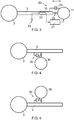
- Figure 4 illustrates an example in which a podded or auxiliary fuel tank 30 is mounted below the wing 2 and figure 5 illustrates schematically an example in which a podded or auxiliary fuel tank 30 is mounted above the wing 2.
- the active support 20 and variants thereof may be the same as those described above with reference to figures 2 and 3 .
- the body mounted to the aircraft structure by the active support may be an auxiliary power unit housed in the empennage or near the tail 5 of the aircraft 1, a landing gear mounted to the underside of the wings 2 or the fuselage 3, or payload carried within the fuselage 3 of the aircraft 1.
- the position of the mass does not need to be at the tip of the wing 2, although this is typically the area with the largest deflection for a fixed wing aircraft.
- the mass could be positioned above or below the wing anywhere along its length (span).
- preload could be applied to the spring 24 to prevent deflection below a specified load level.
- Uses of hinges, rails, spigots and pin joints could be used to constrain the deflection of the mass in one or more directions (translation or rotation).
- one or more spigots may provide restraint in all directions except for deflections along the axis of the spigot 26. This would allow the mass of the wing tip tank 11 to remain in position to reduce the impact of aircraft centre of gravity when deflections occur.
- the optional spring 24 and damper 25 (not shown in figure 6 ), if provided, could then be aligned to the spigot axis to manage relative deflection.
- a hinge would constrain deflection but permit rotation around its axis.
- a linear or rotational spring/damper could be used to manage rotation, as shown in figure 7 .
- the actuator 21 of the active support 20 is a rotary actuator in the example shown in figure 7 as different than the linear actuators 21 described previously.
- the hinge 27 allows rotation only about a substantially horizontal (chordwise extending) axis in the configuration shown in figure 7 , which rotation at the hinge 27 creates vertical deflection of the wing tip tank 11.
- the wing tip tank 11 is only one example of a body having a mass mounted by the active support 20 and the configuration shown in figure 7 may be particularly well suited to a variant (not shown) in which the body having the mass is a folding wing tip connected to the wing 2 by the hinge 27.
- the folding wing tip may be used to reduce the aircraft span when the aircraft is on the ground to meet gate limits, for example.
- the tip tank 11 or other body is connected to the aircraft structure such as the tip end 10 of the wing 2 by a variant of the active support 20 in which the support is configured as a linear cantilever 28.
- the linear cantilever may be a 'leaf spring' style connection, such as using semi-flexible carbon fibre beams or similar. This would provide a good level of constraint between the mass of the tip tank 11 and the wing 2, but allow deflection between them in the same manner as a leaf spring.
- the actuator 21 and its control may be as described previously in any of the figures 6-8 .
- An active damper can also be used between the mass of the body and the aircraft structure. This would allow the magnitude of damping to be varied, in conjunction with the flight control system requirements to allow optimal displacement (and rate of displacement) of the mass relative to the aircraft structure to further mitigate load increases through the flight regime. Similarly a variable gas pressure spring (or progressive rate spring) could be used to tailor the dynamic response as the mass of the system changes in flight.
- the mass was provided by a fuel volume, it is likely that the mass will decrease during operation of the aircraft.
- the mass of the aircraft will also evolve during flight as the fuel contained within the main wing tanks is consumed by the engines, so it may be appropriate to match the mass, spring rate and damping to the aircraft condition. This could be achieved by transferring fuel in/out of the wing tip tank 11, adapting the damping and varying the spring rate, or limiting deflection, possibly using the actuator 21.
- a locking system 40 may be used to restrain the tip tank 11, or limit degrees of freedom provided by the active support 20, under specific circumstances (e.g. crash cases, low fuel volume or systems failure cases).
- a latch 41 may be provided with the active support 20.
- a float 42 on a sliding rail 43 may be used to sense when the level of fuel 44 within the tip tank 11 reaches one or more predetermined levels. When the level of fuel within the tip tank 11 is above a predetermined level the latch 41 is unlatched enabling the active support 20 to provide its full range of movement for the tip tank 11 in at least one degree of freedom.
- the latch 41 When the level of fuel 44 within the tip tank 11 falls below a predetermined value the latch 41 is latched to restrain further relative deflection between the tip tank 11 and the wing 2. When the latch 41 is latched the active support becomes a substantially rigid connection.
- the latch may be electrical or mechanical and may be linked to the flight control system or flight computers. Activation of the latch 41 may also be pilot or auto pilot controlled. This locking system 40 may be applied to any of the above described examples.
- a faired installation may be appropriate, as shown in Figure 10 .
- a part of the aircraft structure 50 would encapsulate the body 51 having the mass and have a desirable external shape (such as an aerofoil or other lifting surface).
- a gap 52 exists between the body 51 and structure 50, such that a system of active supports 53 suspend the body 50.
- the gap 52 allows relative deflection of the body 51 relative to the structure 50.
- the system active supports 53 may include an optional spring/damper and be controlled in a similar manner to the above described embodiments.
- a further benefit of this configuration is the limit to deflection provided by the gap 52 closing between the body 51 and the structure 50. At high load levels, direct contact between the two would eliminate the relative deflection and secure the elements together, which may be useful for a crash case, for example.
- a different practical realisation of the same concept could be achieved by filling the gap 52 between body 51 and the structure 50 with a fluid.
- the fluid may be a gas or liquid and the pressure and viscosity, for example, could be chosen to adjust the mechanical characteristic of such a system.
- a free body diagram for a purely exemplary system comprising an aircraft fuselage, wing and tip tank responding a vertical gust excitation is represented in Figure 11 , with the vertical displacement shown along the horizontal axis for convenience.
- the acceleration due to the gust "a” is applied to the fuselage (considered as the "ground” of the system).
- the external force “p”, representing the change in lift due to the gust, is applied to the wing. Accelerations for the various components of the system can be computed by successive derivations of the displacement time histories.
- An equivalent representation can be setup with rotational springs, considering moments of inertia and rotational displacements in place of masses and linear displacement.
- the actuator within the active support aids the natural restoring force due to the elastic connection between wing and the tip tank (damper).
- the control strategy proposed for the system is presented diagrammatically in Figure 12 .
- a feedback control loop is established between the acceleration, a, input due to the gust (at the fuselage), and acceleration on the wing, p, output by the mechanical system.
- the aim of the PID controller(s) is to minimise the difference between those input/output accelerations, in effect limiting (or eliminating) the effects of wing flexibility during the dynamic response to the gust.
Landscapes
- Engineering & Computer Science (AREA)
- Aviation & Aerospace Engineering (AREA)
- Automation & Control Theory (AREA)
- Physics & Mathematics (AREA)
- Mechanical Engineering (AREA)
- General Engineering & Computer Science (AREA)
- Radar, Positioning & Navigation (AREA)
- Remote Sensing (AREA)
- General Physics & Mathematics (AREA)
- Acoustics & Sound (AREA)
- Manufacturing & Machinery (AREA)
- Fluid Mechanics (AREA)
- Transportation (AREA)
- Transmission Devices (AREA)
- Aerodynamic Tests, Hydrodynamic Tests, Wind Tunnels, And Water Tanks (AREA)
- Vibration Prevention Devices (AREA)
- Details Of Aerials (AREA)
- Toys (AREA)
Abstract
Description
- The present invention relates to an aircraft responsive to a dynamic input, and a method of reducing loads on an aircraft structure.
- Current aircraft systems use the controlled motion of fast-acting movable flight control surfaces (e.g. ailerons and spoilers) to redistribute aerodynamic loads. These systems are commonly known as loads alleviation function (LAF) systems and typically aim to reduce the wing bending moment at the root.
- More recently, LAFs have been developed which, in addition to acting to affect steady state loads (initial conditions), act to respond to dynamic loads such as those which develop during a gust encounter.
- A gust LAF system reduces the effect of gust loads on the aircraft by measuring the upward acceleration of the aircraft and comparing that with the acceleration commanded by the pilot. Any discrepancy may be added as a correction signal by the flight control system to signals controlling the deflection of the control surfaces in order to counteract the accelerations caused by wind gusts, thereby also reduce the wing bending moments.
- A first aspect of the invention provides an aircraft comprising a structure at least part of which is capable of generating aerodynamic lift, and a body having a mass movably mounted to a portion of the structure by an active support, wherein the active support includes an actuator configured to move the body relative to the portion of the structure, and a controller for controlling movement of the actuator in response to a dynamic input, wherein the active support is configured to provide a range of movement for the body in at least one degree of freedom, and the actuator is configured to move the body across the entire range of movement in said one degree of freedom in a time period of less than 3 seconds, and wherein the actuator is configured to move the body sufficiently rapidly to generate an inertial force that is equal to or greater than any aerodynamic force generated by the body during that movement of the body.
- A further aspect of the invention provides a method of reducing loads on an aircraft structure having at least a part capable of generating aerodynamic lift, and a body having a mass movably mounted to a portion of the structure by an active support, wherein the active support includes an actuator configured to move the body relative to the portion of the structure, wherein the active support is configured to provide a range of movement for the body in at least one degree of freedom, and the actuator is configured to move the body across the entire range of movement in said one degree of freedom in a time period of less than 3 seconds, the method comprising moving the body relative to the portion of the structure in response to a dynamic input and sufficiently rapidly to generate an inertial force equal to or greater than any aerodynamic force generated by the body during that movement of the body.
- The invention is advantageous in that the mass can be used to affect the dynamic response of at least the portion of the aircraft structure to which the mass is mounted so the loads developed during an event causing movement of the aircraft structure can be reduced.
- The magnitude of the mass may be selected according to the intended dynamic response of the structure. For example, a relatively larger mass may be used where the dynamic response is relatively slower, whereas a relatively smaller mass may be used where the dynamic response is relatively faster.
- The active support in this context is any support structure which allows flexibility or movement between the body and the structure and which movement is actively controlled by the actuator. The active support may include a spring, either within the actuator or as a separate part, acting to bias the active support to one or more positions. The active support may include a damper, either within the actuator or as a separate component, acting to dissipate kinetic energy.
- The body may include one or more of: a wing tip fuel tank, auxiliary fuel tank, podded fuel tank, a main engine, an auxiliary power unit, a landing gear, a wing tip device or payload (e.g. passengers, cargo, ordnance, etc.) of the aircraft.
- In one example, the invention may be used to reduce aircraft wing loads by controlling the dynamic response of a relatively heavy mass attached to the wing by the active support. In an example where the relatively heavy mass is a wing tip fuel tank the active support may reduce wing loads that may otherwise exceed a loads limit such that the wing tip tank may be fitted or retrofitted without modification to an existing wing structure.
- In another example, the invention may be used in mounting the engine/pylon, or any external storage (e.g. for military applications), onto the wing to limit the load introduction into the wing-box due to the engine dynamics.
- Alternatively, the invention may be used in conjunction with a folding aircraft wing-tip where the hinge between the main wing and the folding wing-tip is the active support, and the body is the folding wing-tip part outboard of the hinge.
- Further alternatively, the wing tip fuel tank mounted using the active support may be used in conjunction with a relatively large wing tip device mounted onto the tip end of the wing. Fitting or retrofitting a large winglet or other wing tip device may typically require strengthening work or other modifications to the wing structure, particularly in the outboard sections of the wing. The wing tip device may be configured to generate relatively large aerodynamic and structural forces without modification to an existing wing structure, or with reduced structural modification, when used in conjunction with the wing tip fuel tank mounted using the active support. This may allow for an additional variable in the design space of the wing tip device, allowing to control inertia forces.
- The dynamic input may be a signal from a sensor mounted to the aircraft.
- The sensor may be one or more of: an air pressure sensor, a position sensor, an accelerometer, an air densitometer, an angle of attack vane or strain gauge.
- The active support may be configured to provide a range of movement for the body in a plurality of degrees of freedom, e.g. up to six degrees of freedom. Where the active support is configured to support more than one body, the active support may be configured to provide a range of movement for the bodies in more than six degrees of freedom.
- The mass of the body may be substantially constant.
- The mass of the body may be substantially constant during the 3 second time period.
- The mass of the body may be substantially constant for at least a duration an order of magnitude greater than the 3 second time period.
- The dynamic input may be representative of an aerodynamic load or a ground load acting on the aircraft, or of an unbalanced dynamic load generated by a part of the aircraft.
- The dynamic input may be an aerodynamic gust load.
- The controller may be configured to provide loads alleviation for the structure of the aircraft.
- The dynamic input may be an aerodynamic gust load sensed a distance in front of and/or at any point on the aircraft.
- The method may provide loads alleviation for the structure of the aircraft.
- Where the aircraft has a passenger cabin, and method may reduce the magnitude of external loads on the structure that are imparted to the passenger cabin.
- The dynamic input may be received from a sensor forming part of a loads alleviation system coupled to one or more flight control surfaces of the aircraft.
- The dynamic input may be a pilot controlled input, e.g. a pilot induced oscillation or other unfavourable pilot-vehicle interaction.
- Embodiments of the invention will now be described with reference to the accompanying drawings, in which:
-
Figure 1 illustrates a plan view of an aircraft having wing tip fuel tanks; -
Figure 2 illustrates schematically a wing tip mounted body attached to the wing by an active support according to a first example; -
Figure 3 illustrates schematically a wing tip mounted body attached to the wing by an active support according to a second example; -
Figure 4 illustrates schematically a body attached below the wing by an active support according to a third example; -
Figure 5 illustrates schematically a body attached above the wing by an active support according to a fourth example; -
Figure 6 illustrates schematically a wing tip mounted body attached to the wing by an active support according to a fifth example; -
Figure 7 illustrates schematically a wing tip mounted body attached to the wing by an active support according to a sixth example; -
Figure 8 illustrates schematically a wing tip mounted body attached to the wing by an active support according to a seventh example; -
Figure 9 illustrates schematically a body attached to the wing by an active support having a releasable locking mechanism according to an eighth example; -
Figure 10 illustrates schematically a body attached within a fairing of the aircraft structure by an active support according to a ninth example; -
Figure 11 illustrates a free body diagram of the body attached to the aircraft structure by the active support; and -
Figure 12 illustrates a control strategy for the active support. -
Figure 1 illustrates a plan view of anaircraft 1 havingwings 2 connected to afuselage 3. Thewings 2 are the main lift generating surfaces for the aircraft and so the aircraft structure has at least a part capable of generating lift. Theaircraft 1 has anose 4 and atail 5. Adjacent to thetail 5 are horizontal andvertical stabilisers aircraft fuselage 3. Theaircraft 1 has under-wing mountedengines 8. Eachwing 2 and the horizontal andvertical stabiliser surfaces aircraft 1 shown is a fixed wing jet passenger aircraft, although in other examples the aircraft may be any aircraft type, including fixed or rotary wing, civil or military, passenger, cargo, general aviation, manned or unmanned, etc. without limitation. - Each of the
wings 2 has aroot end 9 adjacent to thefuselage 3 and atip end 10 opposite the root end. Mounted at thetip end 10 of eachwing 2 is a wing tip fuel tank pod 11. Thetip tanks 11 are arranged to carry an additional fuel volume to supplement the fuel volume contained within the main fuel tanks inside thewings 2. Thetip tanks 11 may therefore extend the operational range of theaircraft 1 and may be detachable such that thetip tanks 11 may be used for only certain flight missions and may be removed for other flight missions where the additional fuel volume is not required. - Beneficially, the
tip tanks 11 may remain full of fuel towards the end of a flight mission, when the majority of the fuel held in the main wing tanks has been used by themain engines 8. Keeping a relatively heavy mass at thetip end 10 of thewings 2 may be desirable in some circumstances to counteract the aerodynamic lift of thewings 2, thereby reducing wing bending moments, particularly at theroot end 9, and/or torque or shear force. However, under other conditions the relatively heavy mass of thetip tanks 11 may actually be undesirable and may lead to an increase in the wing bending moment, torque or shear. - As shown in
figure 2 anactive support 20 is used to mount thewing tip tank 11 to thewing 2. In the illustrated example thewing tip tank 11 is an example of a body having a mass. In the following discussion thetip tank 11 is intended purely as one example of a body having a mass, and the comments may apply similarly to other bodies having a mass. Thewing tip tank 11 is movably mounted to a portion of the aircraft structure, which in the illustrated example is thetip end 10 of thewing 2. In the following discussion thetip end 10 of thewing 2 is intended purely as one example of a portion of the aircraft structure, and the comments may apply similarly to other portions of the aircraft structure. - The
active support 20 includes anactuator 21 configured to move thetip tank 11 relative to thetip end 10 of thewing 2. Acontroller 22 is connected (e.g. electrically) to asensor 23 and to theactuator 21. Thesensor 23 is configured to output a signal representative of a dynamic input. The sensor may be an air pressure sensor, a position sensor, an accelerometer, an air densitometer, an angle of attack vane, strain gauge, etc. without limitation. The dynamic input is a signal representative of an air pressure external to theaircraft 1, a position (either of theaircraft 1 in three dimensional space, or a part of the aircraft relative to some other part of the aircraft), an acceleration (either of the aircraft as a whole or a portion of the aircraft), a density of ambient air external to the aircraft, an angle of attack of the whole or part of the aircraft relative to the freestream flow, or a strain acting on one or more parts of the aircraft. - The
controller 22 is configured to receive the dynamic input signal from thesensor 23 and to output a command for theactuator 21 to move thewing tip tank 11 relative to thetip end 10 of thewing 2. - The
active support 20 is configured to provide a range of movement for thetip tank 11 in at least one degree of freedom and theactuator 21 is configured to move thetip tank 11 across the entire range of movement in that one degree of freedom in a period of time that is less than three seconds. Theactuator 21 is configured to move thetip tank 11 sufficiently rapidly to generate an inertial force (due to the mass of the tip tank and its contents) that is equal to or greater than any aerodynamic force generated by thetip tank 11 during that movement of thetip tank 11 by theactuator 21. - The one or more degrees of freedom provided by the
active support 20 may include a translation and/or rotation of thetip tank 11 relative to thetip end 10 of thewing 2. For example, thetip tank 11 may be configured to permit movement of thetip tank 11 or about one or more orthogonal axes. For example, thetip tank 11 may be constrained for movement vertically and or horizontally relative to the motion of thewing 2. Anoptional spring 24 is shown coupled between thetip tank 11 and thetip end 10 of thewing 2. Thespring 24 is adapted to bias thetip tank 11 relative to thetip end 10 of thewing 2. The function of thespring 24 may be incorporated in theactuator 21, or alternatively the biasing action of thespring 24 may be provided in addition to a biasing spring action within theactuator 21. - Operation of the schematic example illustrated in
figure 2 will now be described in the context of controlling the inertial response of thetip tank 11 to a gust load. Thesensor 23 may be, for example, either an accelerometer mounted somewhere on theaircraft 1, an air pressure sensor mounted near thenose 4 of theaircraft 1, or a forward looking air densitometer such as a LIDAR sensor, or angle of attack vane mounted near thenose 4 of theaircraft 1, or a strain gauge mounted somewhere on the structure of theaircraft 1. Any sensor capable of sensing a wind gust load may be used for this purpose. - Regardless of which type of sensor is deployed the
sensor 23 is adapted to detect a wind gust either before it has an effect on theaircraft 1, or whilst the wind gust is acting on theaircraft 1. The wind gust typically acts to increase or decrease the lift generated by thewing 2. This change in lift acting on thewing 2 will change the wing bending moment. To counteract the aerodynamic load acting on thewing 2 due to the gust thecontroller 22 using the input fromsensor 23 calculates a desired response of theactive support 20 to counteract the load acting on thewing 2 due to the wind gust. - The
controller 22 controls the movement ofactuator 21 to move thewing tip tank 11 relative to thetip end 10 of thewing 2. Since thetip tank 11 and its contained fuel volume has a significant mass, moving thetip tank 11 relative to thetip end 10 of thewing 2 generates an inertial force. It will be appreciated that since thetip tank 11 is in the airflow around the aircraft, moving thetip tank 11 will also generate some aerodynamic force as a result of the movement of thetip tank 11 relative to thetip end 10 of thewing 2. However, the inertial force generated by movement of thetip tank 11 by theactuator 21 is at least equal to or greater than (and may be significantly greater than, e.g. an order of magnitude greater) the aerodynamic force generated by thetip tank 11 during that movement of thetip tank 11. - The magnitude of the inertial force generated by movement of the
tip tank 11 relative to thetip end 10 of thewing 2 is proportional to the acceleration of thetip tank 11 during that movement. Therefore, theactuator 21 is configured to move thetip tank 11 sufficiently rapidly to generate the inertial force required to counteract in whole or in part the aerodynamic force generated by the wind gust. To ensure that theactuator 21 can move thetip tank 11 sufficiently rapidly to generate this inertial force, theactuator 21 is configured to move thetip tank 11 across the entire range of movement in the at least one degree of freedom provided by theactive support 20 in a time period of less than three seconds. This time period is similar to the typical duration of a wind gust event which is typically in the region of one to five seconds. During the wind gust event the direction of the wind acting on the aircraft may exert a force in two opposing directions, e.g. upwards and downwards. In this way, theactive support 20 can control the movement of the significant mass of thetip tank 11 to effectively counteract the wind gust. - The
controller 22 andsensor 23 may form part of a flight control system (FCS) of theaircraft 1. The FCS may include a plurality of thesensors 23 of the one or more types described above and may be connected to the pilot or auto pilot controls of the aircraft and also to the various flight control surfaces of the aircraft. In this way, the FCS may provide the gust load alleviation as a combination of movement of the aircraft flight control surfaces and the inertial response of the mass of thewing tip tank 11. In an alternative example, the FCS may be provided separately from thecontroller 22. It is intended that thecontroller 22 is configured to control the inertial response of thewing tip tank 11 independent of a pilot controlled input, although the pilot or auto pilot may activate or deactivate thecontroller 22. - It will be appreciated that whilst in the example illustrated in
figure 2 theactive support 20 provides a range of movement for thewing tip tank 11 in a single degree of freedom, i.e. substantially vertically, in other examples theactive support 20 may be configured to provide a range of movement for the body in a plurality of degrees of freedom up to a maximum of six degrees of freedom. In a further alternative example theactive support 20 may be used to mount a plurality of bodies each having a respective mass and in that example the number of degrees of freedom provided by theactive support 20 may be greater than six. - Considering the relatively rapid movement of the
tip tank 11 by theactuator 21 it is expected that the mass of the tip tank 11 (including its fuel volume) is kept substantially constant. The mass of thetip tank 11 may be maintained substantially constant at least during the three second time period, and preferably the mass of thewind tip tank 11 is kept substantially constant for at least a duration an order of magnitude greater than this three second time period. - Whilst in the above described example the dynamic input is representative of an aerodynamic gust load acting on the
aircraft 1 and the inertial response of thewing tip tank 11 to counter that wind gust, it will be appreciated that theactive support 20 may be configured to generate an inertial force by movement of thetip tank 11 in response to other aerodynamic loads or ground loads acting on the aircraft, e.g. during a manoeuvre whether in flight or on the ground, or upon landing. -
Figure 3 shows a modification of the example described above with reference tofigure 2 which differs only in that adamper 25 is connected between thetip tank 11 and thetip end 10 of thewing 2, and in that the degree of freedom of theactive support 20 is substantially horizontal as different than the substantially vertical degree of freedom shown infigure 2 . It will be appreciated that these two differences between the examples shown infigures 2 and3 are independent and thedamper 25 may be used regardless of the direction or number of degrees of freedom provided by theactive support 20 and vice versa. Thedamper 25 acts to dissipate kinetic energy. Thedamper 25 may either be provided as a separate component to theactuator 21 as shown infigure 3 , or a damping function may be incorporated within theactuator 21. In a further example theactuator 21 may provide a damping function in addition to theseparate damper 25. - Whilst in the above described examples the body mounted by the
active support 20 is awing tip tank 11, it will be appreciated that the body may be other than a wing tip tank. Examples of other bodies may include an auxiliary fuel tank or podded fuel tank, or a main engine mounted either below or above the wing. -
Figure 4 illustrates an example in which a podded orauxiliary fuel tank 30 is mounted below thewing 2 andfigure 5 illustrates schematically an example in which a podded orauxiliary fuel tank 30 is mounted above thewing 2. In bothfigures 4 and 5 theactive support 20 and variants thereof may be the same as those described above with reference tofigures 2 and3 . - In further examples, not shown in the figures, the body mounted to the aircraft structure by the active support may be an auxiliary power unit housed in the empennage or near the
tail 5 of theaircraft 1, a landing gear mounted to the underside of thewings 2 or thefuselage 3, or payload carried within thefuselage 3 of theaircraft 1. - The variety of bodies having a mass, including those listed above, which may be movably mounted to a portion of the aircraft structure by an active support is not to be construed as limited to the examples given in
figures 2-4 above and other examples will be appreciated by those skilled in the art. - As will be apparent from this exemplary list of bodies having a mass which may be connected by the active support, the position of the mass does not need to be at the tip of the
wing 2, although this is typically the area with the largest deflection for a fixed wing aircraft. The mass could be positioned above or below the wing anywhere along its length (span). - To minimize undesirable shifts in the centre of gravity of the aircraft 1 (including local wing effects) it may be desirable to constrain one or more of the degrees of freedom provided by the
active support 20. For example, preload could be applied to thespring 24 to prevent deflection below a specified load level. Uses of hinges, rails, spigots and pin joints could be used to constrain the deflection of the mass in one or more directions (translation or rotation). - In the example depicted
figure 6 , which for purely exemplary purposes is again awing tip tank 11 connected to thetip end 10 of thewing 2, one or more spigots may provide restraint in all directions except for deflections along the axis of thespigot 26. This would allow the mass of thewing tip tank 11 to remain in position to reduce the impact of aircraft centre of gravity when deflections occur. Theoptional spring 24 and damper 25 (not shown infigure 6 ), if provided, could then be aligned to the spigot axis to manage relative deflection. - Similarly, a hinge would constrain deflection but permit rotation around its axis. A linear or rotational spring/damper could be used to manage rotation, as shown in
figure 7 . Theactuator 21 of theactive support 20 is a rotary actuator in the example shown infigure 7 as different than thelinear actuators 21 described previously. Thehinge 27 allows rotation only about a substantially horizontal (chordwise extending) axis in the configuration shown infigure 7 , which rotation at thehinge 27 creates vertical deflection of thewing tip tank 11. - As described previously, the
wing tip tank 11 is only one example of a body having a mass mounted by theactive support 20 and the configuration shown infigure 7 may be particularly well suited to a variant (not shown) in which the body having the mass is a folding wing tip connected to thewing 2 by thehinge 27. The folding wing tip may be used to reduce the aircraft span when the aircraft is on the ground to meet gate limits, for example. - In a further example shown in
figure 8 thetip tank 11 or other body is connected to the aircraft structure such as thetip end 10 of thewing 2 by a variant of theactive support 20 in which the support is configured as alinear cantilever 28. The linear cantilever may be a 'leaf spring' style connection, such as using semi-flexible carbon fibre beams or similar. This would provide a good level of constraint between the mass of thetip tank 11 and thewing 2, but allow deflection between them in the same manner as a leaf spring. - The
actuator 21 and its control may be as described previously in any of thefigures 6-8 . - An active damper can also be used between the mass of the body and the aircraft structure. This would allow the magnitude of damping to be varied, in conjunction with the flight control system requirements to allow optimal displacement (and rate of displacement) of the mass relative to the aircraft structure to further mitigate load increases through the flight regime. Similarly a variable gas pressure spring (or progressive rate spring) could be used to tailor the dynamic response as the mass of the system changes in flight.
- If the mass was provided by a fuel volume, it is likely that the mass will decrease during operation of the aircraft. The mass of the aircraft will also evolve during flight as the fuel contained within the main wing tanks is consumed by the engines, so it may be appropriate to match the mass, spring rate and damping to the aircraft condition. This could be achieved by transferring fuel in/out of the
wing tip tank 11, adapting the damping and varying the spring rate, or limiting deflection, possibly using theactuator 21. - There are circumstances where a selective rigid connection may be required between the body having the mass and the aircraft structure. As shown in
figure 9 alocking system 40 may be used to restrain thetip tank 11, or limit degrees of freedom provided by theactive support 20, under specific circumstances (e.g. crash cases, low fuel volume or systems failure cases). Alatch 41 may be provided with theactive support 20. Afloat 42 on a slidingrail 43 may be used to sense when the level offuel 44 within thetip tank 11 reaches one or more predetermined levels. When the level of fuel within thetip tank 11 is above a predetermined level thelatch 41 is unlatched enabling theactive support 20 to provide its full range of movement for thetip tank 11 in at least one degree of freedom. When the level offuel 44 within thetip tank 11 falls below a predetermined value thelatch 41 is latched to restrain further relative deflection between thetip tank 11 and thewing 2. When thelatch 41 is latched the active support becomes a substantially rigid connection. The latch may be electrical or mechanical and may be linked to the flight control system or flight computers. Activation of thelatch 41 may also be pilot or auto pilot controlled. Thislocking system 40 may be applied to any of the above described examples. - To minimise the aerodynamic disturbance of the mass moving around relative to the wing, a faired installation may be appropriate, as shown in
Figure 10 . A part of theaircraft structure 50 would encapsulate thebody 51 having the mass and have a desirable external shape (such as an aerofoil or other lifting surface). Within the structure 50 agap 52 exists between thebody 51 andstructure 50, such that a system ofactive supports 53 suspend thebody 50. Thegap 52 allows relative deflection of thebody 51 relative to thestructure 50. The systemactive supports 53 may include an optional spring/damper and be controlled in a similar manner to the above described embodiments. - A further benefit of this configuration is the limit to deflection provided by the
gap 52 closing between thebody 51 and thestructure 50. At high load levels, direct contact between the two would eliminate the relative deflection and secure the elements together, which may be useful for a crash case, for example. - A different practical realisation of the same concept could be achieved by filling the
gap 52 betweenbody 51 and thestructure 50 with a fluid. The fluid may be a gas or liquid and the pressure and viscosity, for example, could be chosen to adjust the mechanical characteristic of such a system. - A free body diagram for a purely exemplary system comprising an aircraft fuselage, wing and tip tank responding a vertical gust excitation is represented in
Figure 11 , with the vertical displacement shown along the horizontal axis for convenience. - Where:
- m, k and c are the mass, stiffness and structural damping of the wing,
- md, kd and cd are the mass, stiffness and structural damping of the tip tank system (damper),
- ug, u and ud are the relative displacements of the fuselage ("ground"), the wing and the tip tank (damper),
- a is the fuselage (ground) acceleration and p is an external force applied to the wing.
- The acceleration due to the gust "a" is applied to the fuselage (considered as the "ground" of the system). The external force "p", representing the change in lift due to the gust, is applied to the wing. Accelerations for the various components of the system can be computed by successive derivations of the displacement time histories.
- An equivalent representation can be setup with rotational springs, considering moments of inertia and rotational displacements in place of masses and linear displacement.
- The actuator within the active support aids the natural restoring force due to the elastic connection between wing and the tip tank (damper). The control strategy proposed for the system is presented diagrammatically in
Figure 12 . A feedback control loop is established between the acceleration, a, input due to the gust (at the fuselage), and acceleration on the wing, p, output by the mechanical system. The aim of the PID controller(s) is to minimise the difference between those input/output accelerations, in effect limiting (or eliminating) the effects of wing flexibility during the dynamic response to the gust. - Where the word 'or' appears this is to be construed to mean 'and/or' such that items referred to are not necessarily mutually exclusive and may be used in any appropriate combination.
- Although the invention has been described above with reference to one or more preferred embodiments, it will be appreciated that various changes or modifications may be made without departing from the scope of the invention as defined in the appended claims.
Claims (15)
- An aircraft comprising a structure at least part of which is capable of generating aerodynamic lift, and a body having a mass movably mounted to a portion of the structure by an active support,
wherein the active support includes an actuator configured to move the body relative to the portion of the structure, and a controller for controlling movement of the actuator in response to a dynamic input,
wherein the active support is configured to provide a range of movement for the body in at least one degree of freedom, and the actuator is configured to move the body across the entire range of movement in said one degree of freedom in a time period of less than 3 seconds, and
wherein the actuator is configured to move the body sufficiently rapidly to generate an inertial force that is equal to or greater than any aerodynamic force generated by the body during that movement of the body. - An aircraft according to claim 1, wherein the body includes one or more of: a wing tip fuel tank, auxiliary fuel tank, podded fuel tank, a main engine, an auxiliary power unit, a landing gear, a wing tip device or payload of the aircraft.
- An aircraft according to claim 1 or claim 2, wherein the dynamic input is a signal from a sensor mounted to the aircraft, preferably wherein the sensor is one or more of: an air pressure sensor, a position sensor, an accelerometer, an air densitometer, an angle of attack vane or strain gauge.
- An aircraft according to any preceding claim, wherein the active support is configured to provide a range of movement for the body in up to six degrees of freedom.
- An aircraft according to any preceding claim, wherein the mass of the body is substantially constant, preferably wherein the mass of the body is substantially constant either during the 3 second time period or for at least a duration an order of magnitude greater than the 3 second time period.
- An aircraft according to any preceding claim, wherein the body is exposed to airflow over the aircraft.
- An aircraft according to any preceding claim, wherein the dynamic input is representative of an aerodynamic load or a ground load acting on the aircraft, or of an unbalanced dynamic load generated by a part of the aircraft.
- An aircraft according to any preceding claim, wherein the dynamic input is an aerodynamic gust load.
- An aircraft according to any preceding claim, wherein the controller is configured to provide loads alleviation for the structure of the aircraft.
- An aircraft according to any preceding claim, wherein the aircraft has a passenger cabin, and the controller is configured to reduce the magnitude of external loads on the structure that are imparted to the passenger cabin.
- An aircraft according to any preceding claim, wherein the aircraft is a fixed or rotary wing aircraft.
- A method of reducing loads on an aircraft structure having at least a part capable of generating aerodynamic lift, and a body having a mass movably mounted to a portion of the structure by an active support, wherein the active support includes an actuator configured to move the body relative to the portion of the structure, wherein the active support is configured to provide a range of movement for the body in at least one degree of freedom, and the actuator is configured to move the body across the entire range of movement in said one degree of freedom in a time period of less than 3 seconds, the method comprising moving the body relative to the portion of the structure in response to a dynamic input and sufficiently rapidly to generate an inertial force equal to or greater than any aerodynamic force generated by the body during that movement of the body.
- A method according to claim 12, wherein the dynamic input is representative of an aerodynamic load or a ground load acting on the aircraft, or of an unbalanced dynamic load generated by a part of the aircraft, or wherein the dynamic input is an aerodynamic gust load sensed a distance in front of and/or at any point on the aircraft.
- A method according to any of claims 12 to 13, which provides loads alleviation for the structure of the aircraft, and/or wherein the dynamic input is received from a sensor forming part of a loads alleviation system coupled to one or more flight control surfaces of the aircraft, and/or wherein the dynamic input is a pilot controlled input.
- A method according to any of claims 12 to 14, wherein the body is exposed to airflow over the aircraft.
Applications Claiming Priority (1)
| Application Number | Priority Date | Filing Date | Title |
|---|---|---|---|
| GB1720517.0A GB2569175A (en) | 2017-12-08 | 2017-12-08 | Aircraft with active support |
Publications (1)
| Publication Number | Publication Date |
|---|---|
| EP3501981A1 true EP3501981A1 (en) | 2019-06-26 |
Family
ID=61007073
Family Applications (1)
| Application Number | Title | Priority Date | Filing Date |
|---|---|---|---|
| EP18210365.5A Withdrawn EP3501981A1 (en) | 2017-12-08 | 2018-12-05 | Aircraft with active support |
Country Status (5)
| Country | Link |
|---|---|
| US (1) | US11198503B2 (en) |
| EP (1) | EP3501981A1 (en) |
| KR (1) | KR20190068439A (en) |
| CN (1) | CN110015443A (en) |
| GB (1) | GB2569175A (en) |
Cited By (1)
| Publication number | Priority date | Publication date | Assignee | Title |
|---|---|---|---|---|
| GB2584668A (en) * | 2019-06-10 | 2020-12-16 | Airbus Operations Ltd | An aircraft wing with a moveable wing tip |
Families Citing this family (4)
| Publication number | Priority date | Publication date | Assignee | Title |
|---|---|---|---|---|
| CN109264003B (en) * | 2018-09-04 | 2021-11-12 | 西北工业大学 | Thrust converter of pulse detonation engine |
| DE102018219179B3 (en) * | 2018-11-09 | 2019-12-05 | Siemens Aktiengesellschaft | Gust reduction in an aircraft |
| GB2591252A (en) * | 2020-01-22 | 2021-07-28 | Airbus Operations Ltd | Load control for an aircraft wing |
| WO2025119462A1 (en) * | 2023-12-06 | 2025-06-12 | Destinus Sa | Cryogenic tank for an aircraft with hydraulic actuators |
Citations (8)
| Publication number | Priority date | Publication date | Assignee | Title |
|---|---|---|---|---|
| JPH04306197A (en) * | 1991-04-01 | 1992-10-28 | Mitsubishi Electric Corp | On-board pod for aircraft |
| DE10226241A1 (en) * | 2002-06-13 | 2004-01-08 | Airbus Deutschland Gmbh | Aircraft fuselage movements suppression method, involves using controlled mass-system installed in aircraft |
| EP2233395A1 (en) * | 2009-03-24 | 2010-09-29 | EADS Deutschland GmbH | Winglet with autonomously actuated tab |
| EP2860100A1 (en) * | 2013-10-09 | 2015-04-15 | The Boeing Company | Aircraft wing-to-fuselage joint with active suspension and method |
| US9266609B1 (en) * | 2014-10-20 | 2016-02-23 | Insitu, Inc | Dual mode flight vehicle |
| KR20160077703A (en) * | 2014-12-24 | 2016-07-04 | 한국항공우주연구원 | Pitch control apparatus and method for aircraft of weight moving type |
| WO2016144421A1 (en) * | 2015-03-10 | 2016-09-15 | Qualcomm Incorporated | Adjustable weight distribution for multi-rotor helicopter drone |
| EP3101504A2 (en) * | 2015-06-04 | 2016-12-07 | The Boeing Company | Gust compensation system and method for aircraft |
Family Cites Families (6)
| Publication number | Priority date | Publication date | Assignee | Title |
|---|---|---|---|---|
| US4343447A (en) * | 1980-03-28 | 1982-08-10 | The United States Of America As Represented By The Administrator Of The National Aeronautics And Space Administration | Decoupler pylon: wing/store flutter suppressor |
| DE3136320C2 (en) * | 1981-09-12 | 1983-10-20 | Deutsche Forschungs- und Versuchsanstalt für Luft- und Raumfahrt e.V., 5000 Köln | Method and device for suppressing the external load wing flutter of aircraft |
| FR2531676A1 (en) * | 1982-08-11 | 1984-02-17 | Onera (Off Nat Aerospatiale) | PROCESS AND INSTALLATION FOR REDUCING THE SHOCKING OF THE AIRCRAFT VANE BY MEANS OF ACTIVE GOVERNORS |
| GB0006420D0 (en) * | 2000-03-16 | 2000-12-20 | British Aerospace | Flight control system for an aircraft |
| FR2874205B1 (en) * | 2004-08-12 | 2006-09-15 | Eurocopter France | METHOD AND APPARATUS FOR ACTIVE SUSPENSION OF A ROTARY WING AIRCRAFT |
| US20170088257A1 (en) * | 2015-09-30 | 2017-03-30 | Bell Helicopter Textron Inc. | Unified control of multiple active systems for helicopter vibration suppression |
-
2017
- 2017-12-08 GB GB1720517.0A patent/GB2569175A/en not_active Withdrawn
-
2018
- 2018-11-30 KR KR1020180152180A patent/KR20190068439A/en not_active Withdrawn
- 2018-12-05 EP EP18210365.5A patent/EP3501981A1/en not_active Withdrawn
- 2018-12-05 US US16/210,699 patent/US11198503B2/en active Active
- 2018-12-06 CN CN201811487084.0A patent/CN110015443A/en active Pending
Patent Citations (8)
| Publication number | Priority date | Publication date | Assignee | Title |
|---|---|---|---|---|
| JPH04306197A (en) * | 1991-04-01 | 1992-10-28 | Mitsubishi Electric Corp | On-board pod for aircraft |
| DE10226241A1 (en) * | 2002-06-13 | 2004-01-08 | Airbus Deutschland Gmbh | Aircraft fuselage movements suppression method, involves using controlled mass-system installed in aircraft |
| EP2233395A1 (en) * | 2009-03-24 | 2010-09-29 | EADS Deutschland GmbH | Winglet with autonomously actuated tab |
| EP2860100A1 (en) * | 2013-10-09 | 2015-04-15 | The Boeing Company | Aircraft wing-to-fuselage joint with active suspension and method |
| US9266609B1 (en) * | 2014-10-20 | 2016-02-23 | Insitu, Inc | Dual mode flight vehicle |
| KR20160077703A (en) * | 2014-12-24 | 2016-07-04 | 한국항공우주연구원 | Pitch control apparatus and method for aircraft of weight moving type |
| WO2016144421A1 (en) * | 2015-03-10 | 2016-09-15 | Qualcomm Incorporated | Adjustable weight distribution for multi-rotor helicopter drone |
| EP3101504A2 (en) * | 2015-06-04 | 2016-12-07 | The Boeing Company | Gust compensation system and method for aircraft |
Cited By (1)
| Publication number | Priority date | Publication date | Assignee | Title |
|---|---|---|---|---|
| GB2584668A (en) * | 2019-06-10 | 2020-12-16 | Airbus Operations Ltd | An aircraft wing with a moveable wing tip |
Also Published As
| Publication number | Publication date |
|---|---|
| US20190176970A1 (en) | 2019-06-13 |
| GB201720517D0 (en) | 2018-01-24 |
| GB2569175A (en) | 2019-06-12 |
| US11198503B2 (en) | 2021-12-14 |
| CN110015443A (en) | 2019-07-16 |
| KR20190068439A (en) | 2019-06-18 |
Similar Documents
| Publication | Publication Date | Title |
|---|---|---|
| US11198503B2 (en) | Aircraft with active support | |
| EP3000722B1 (en) | Aircraft | |
| EP2860100B1 (en) | Aircraft wing-to-fuselage joint with active suspension and method | |
| US8820676B2 (en) | Airplane with pitch and yaw command by propulsion system | |
| EP2899118B1 (en) | Rotorcraft with a fuselage and at least one main rotor | |
| Nguyen et al. | Aeroelastic modeling of elastically shaped aircraft concept via wing shaping control for drag reduction | |
| JP4405704B2 (en) | Improvements in rotor tilt convertible aircraft. | |
| US10279892B2 (en) | Tiltrotor aircraft having active wing extensions | |
| US20100059623A1 (en) | Aircraft with its fuselage suspended under the wing | |
| US11718396B2 (en) | Active sail blade | |
| US11685516B2 (en) | Passive gust-load-alleviation device | |
| AU2004284064A1 (en) | Tailboom-stabilized VTOL aircraft | |
| EP1264226B1 (en) | Flight control system for an aircraft | |
| KR20260027175A (en) | Systems and methods for aircraft load relief | |
| WO2021148338A1 (en) | Load control for an aircraft wing | |
| CN120903019A (en) | Fixed wing small aircraft tilting type composite thrust system | |
| JP4534018B2 (en) | Flying machine | |
| EP3617066B1 (en) | Redundant impact-resistant structure | |
| Hönlinger et al. | Structural aspects of active control technology | |
| Wildschek et al. | Gust load alleviation on a large blended wing body airliner | |
| WO2024068661A1 (en) | A control unit, a force actuation element and a method for adjusting an element of an aircraft | |
| CN114746335B (en) | Device, arrangement and method for regulating and controlling an actuation system of an aircraft | |
| US11851172B1 (en) | Apparatus, system and method for a supplemental wing for a rotary wing aircraft | |
| US12179904B2 (en) | Compliant root structure for connecting an airfoil to a fuselage | |
| US11814162B2 (en) | Rotatable winglets for a rotary wing aircraft |
Legal Events
| Date | Code | Title | Description |
|---|---|---|---|
| PUAI | Public reference made under article 153(3) epc to a published international application that has entered the european phase |
Free format text: ORIGINAL CODE: 0009012 |
|
| STAA | Information on the status of an ep patent application or granted ep patent |
Free format text: STATUS: THE APPLICATION HAS BEEN PUBLISHED |
|
| AK | Designated contracting states |
Kind code of ref document: A1 Designated state(s): AL AT BE BG CH CY CZ DE DK EE ES FI FR GB GR HR HU IE IS IT LI LT LU LV MC MK MT NL NO PL PT RO RS SE SI SK SM TR |
|
| AX | Request for extension of the european patent |
Extension state: BA ME |
|
| STAA | Information on the status of an ep patent application or granted ep patent |
Free format text: STATUS: REQUEST FOR EXAMINATION WAS MADE |
|
| 17P | Request for examination filed |
Effective date: 20191216 |
|
| RBV | Designated contracting states (corrected) |
Designated state(s): AL AT BE BG CH CY CZ DE DK EE ES FI FR GB GR HR HU IE IS IT LI LT LU LV MC MK MT NL NO PL PT RO RS SE SI SK SM TR |
|
| STAA | Information on the status of an ep patent application or granted ep patent |
Free format text: STATUS: EXAMINATION IS IN PROGRESS |
|
| STAA | Information on the status of an ep patent application or granted ep patent |
Free format text: STATUS: THE APPLICATION HAS BEEN WITHDRAWN |
|
| 17Q | First examination report despatched |
Effective date: 20201008 |
|
| 18W | Application withdrawn |
Effective date: 20201019 |