EP2860100B1 - Aircraft wing-to-fuselage joint with active suspension and method - Google Patents
Aircraft wing-to-fuselage joint with active suspension and method Download PDFInfo
- Publication number
- EP2860100B1 EP2860100B1 EP14187327.3A EP14187327A EP2860100B1 EP 2860100 B1 EP2860100 B1 EP 2860100B1 EP 14187327 A EP14187327 A EP 14187327A EP 2860100 B1 EP2860100 B1 EP 2860100B1
- Authority
- EP
- European Patent Office
- Prior art keywords
- wing
- fuselage
- aircraft
- active suspension
- sensors
- Prior art date
- Legal status (The legal status is an assumption and is not a legal conclusion. Google has not performed a legal analysis and makes no representation as to the accuracy of the status listed.)
- Active
Links
- 239000000725 suspension Substances 0.000 title claims description 96
- 238000000034 method Methods 0.000 title claims description 8
- RZVHIXYEVGDQDX-UHFFFAOYSA-N 9,10-anthraquinone Chemical compound C1=CC=C2C(=O)C3=CC=CC=C3C(=O)C2=C1 RZVHIXYEVGDQDX-UHFFFAOYSA-N 0.000 claims description 19
- 230000004044 response Effects 0.000 claims description 15
- 238000005452 bending Methods 0.000 description 20
- 238000010586 diagram Methods 0.000 description 13
- 230000000694 effects Effects 0.000 description 12
- 235000021110 pickles Nutrition 0.000 description 8
- 230000007246 mechanism Effects 0.000 description 7
- 230000035939 shock Effects 0.000 description 7
- 230000008859 change Effects 0.000 description 5
- 238000013461 design Methods 0.000 description 4
- 238000009826 distribution Methods 0.000 description 4
- 239000006096 absorbing agent Substances 0.000 description 3
- 230000008901 benefit Effects 0.000 description 3
- 238000013016 damping Methods 0.000 description 3
- 238000012986 modification Methods 0.000 description 3
- 230000004048 modification Effects 0.000 description 3
- 238000012545 processing Methods 0.000 description 3
- 230000003068 static effect Effects 0.000 description 3
- 238000012546 transfer Methods 0.000 description 3
- 230000007704 transition Effects 0.000 description 3
- 230000005540 biological transmission Effects 0.000 description 2
- 238000006243 chemical reaction Methods 0.000 description 2
- 230000001143 conditioned effect Effects 0.000 description 2
- 230000008846 dynamic interplay Effects 0.000 description 2
- 230000003993 interaction Effects 0.000 description 2
- 238000002955 isolation Methods 0.000 description 2
- 238000005304 joining Methods 0.000 description 2
- 238000012544 monitoring process Methods 0.000 description 2
- 238000004513 sizing Methods 0.000 description 2
- 235000006508 Nelumbo nucifera Nutrition 0.000 description 1
- 240000002853 Nelumbo nucifera Species 0.000 description 1
- 235000006510 Nelumbo pentapetala Nutrition 0.000 description 1
- 230000001133 acceleration Effects 0.000 description 1
- 230000002238 attenuated effect Effects 0.000 description 1
- 230000006399 behavior Effects 0.000 description 1
- 230000009286 beneficial effect Effects 0.000 description 1
- 238000010276 construction Methods 0.000 description 1
- 238000011161 development Methods 0.000 description 1
- 238000006073 displacement reaction Methods 0.000 description 1
- 239000012530 fluid Substances 0.000 description 1
- 230000009916 joint effect Effects 0.000 description 1
- 230000010355 oscillation Effects 0.000 description 1
- 238000005096 rolling process Methods 0.000 description 1
Images


Classifications
-
- B—PERFORMING OPERATIONS; TRANSPORTING
- B64—AIRCRAFT; AVIATION; COSMONAUTICS
- B64C—AEROPLANES; HELICOPTERS
- B64C1/00—Fuselages; Constructional features common to fuselages, wings, stabilising surfaces or the like
- B64C1/26—Attaching the wing or tail units or stabilising surfaces
-
- B—PERFORMING OPERATIONS; TRANSPORTING
- B64—AIRCRAFT; AVIATION; COSMONAUTICS
- B64C—AEROPLANES; HELICOPTERS
- B64C3/00—Wings
- B64C3/38—Adjustment of complete wings or parts thereof
Landscapes
- Engineering & Computer Science (AREA)
- Mechanical Engineering (AREA)
- Aviation & Aerospace Engineering (AREA)
- Vehicle Body Suspensions (AREA)
- Vibration Prevention Devices (AREA)
Description
- The present application relates to aircraft structures. In particular, the present application relates to an aircraft wing-to-fuselage joint with an active suspension connection. The technical field is illustrated by the prior art document
FR-A1-2 935 351 - Fixed-wing aircraft generally include a fuselage and a main wing that supports the fuselage. Aerodynamic forces upon the main wing are transmitted from the wing to the aircraft fuselage, and the load of the fuselage is imposed upon the main wing. The wing-to-fuselage joint, or the structural connection between the main wing and the fuselage, is thus a major component of the airframe. Through this connection the wing transmits significant structural loads to the aircraft fuselage, including forces that move the aircraft as a whole and also structural stresses such as bending stress, torsional stress, vibration, etc.
- Different variants of fixed wing-to-body joints, each having various limitations, have been used on commercial aircraft for decades. Currently, there are several common structural configurations for joining the main wing to the fuselage of a commercial airplane. These various configurations generally present a structurally indeterminate wing-to-body connection which requires the fuselage structure to be capable of sustaining deflections imposed by wing bending. These deflections present the significant issue of fuselage deformation as a result of wing bending.
- Stress transmitted from aircraft wings into the fuselage via the wing-to-body joint is a significant concern in aircraft design, since it affects the strength, durability and other aspects of the aircraft. Existing rigid wing attachment points present limitations to the fuselage/wing construction and sizing due to deflections imposed upon the fuselage by wing bending. For example, many known wing-to-body joints transfer wing bending moments directly to the fuselage. Other known wing-to-body joints can at least partially isolate the fuselage from wing bending moments, but the fuselage contour can still be forced out of shape by horizontal and vertical forces upon the wing. Also, some prior wing-to-body joint solutions generally do not separate wing torsion and vibration modes from the fuselage pitch mode as a contributor to wing flutter phenomena. In addition to structural and operational effects on the airframe, many existing wing-to-body joint configurations have significant limitations in suppressing turbulence effects and wing-mounted engine vibrations, which have great effects on passenger comfort.
- The present application is directed toward at least one of the above-mentioned concerns.
- In accordance with one embodiment thereof, the present disclosure provides an aircraft, comprising a fuselage, a wing and a decoupled joint, interconnecting the fuselage and the wing, wherein the joint is decoupled using an active suspension system comprising a plurality of actuators, connected between the wing and the fuselage, the active suspension system being configured to selectively adjust a relative position of the wing and fuselage in response to dynamic loads upon the wing and/or the fuselage, the active suspension system comprising at least four actuators connected between the wing and the fuselage, the active suspension system comprising four actuator groups, each positioned at one of four comers of a wing main spar assembly, each actuator group comprising three actuators oriented at substantially orthogonal angles.
- In accordance with another embodiment thereof, the disclosure provides a method of adapting an aircraft to attenuate forces between a wing and a fuselage thereof. The method includes providing a plurality of sensors upon the aircraft, configured for sensing motion and/or mechanical stress of the wing and/or the fuselage and producing signals indicative thereof, and providing a plurality of active suspension elements interconnecting the wing and the fuselage, the active suspension elements being configured to move at least in response to the signals, to adjust a position of the wing with respect to the fuselage, wherein the plurality of active suspension elements comprises four actuator groups, each positioned at one of four comers of a wing main spar assembly, each actuator group comprising three actuators oriented at substantially orthogonal angles.
-
-
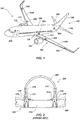
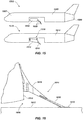
FIG. 1 is a perspective view of an embodiment of an aircraft having a wing-to-body joint with an active suspension system in accordance with the present disclosure; -
FIG. 2 is a cross-sectional view of an aircraft fuselage at the wing joint location, the aircraft having a pickle fork-type wing-to-body joint. -
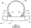
FIG. 3 is a cross-sectional view of an aircraft fuselage at the wing joint location, the aircraft having a pin-type wing-to-body joint. -
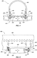
FIG. 4 is a cross-sectional diagram of an aircraft fuselage at the wing joint location, the aircraft having an embodiment of a wing-to-body joint with an active suspension system in accordance with the present disclosure. -
FIG. 5 is a side view of the aircraft fuselage and wing structure of the embodiment ofFIG. 4 , showing the fore-to-aft location of actuator components of the wing-to-body joint active suspension system. -
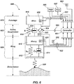
FIG. 6 is schematic diagram of an embodiment of a wing-to-body joint active suspension system in accordance with the present disclosure. -
FIG. 7 is a block diagram of a signal processing control system for a wing-to-body joint active suspension system in accordance with the present disclosure. -
FIG. 8 is a block diagram of an embodiment of control system relationships for a wing-to-body joint active suspension system in accordance with the present disclosure. -
FIG. 9 is a block diagram of an embodiment of the elements of an active wing suspension control system in accordance with the present disclosure. -
FIG. 10 is a top perspective view of an aircraft having an embodiment of a wing-to-body joint active suspension system in accordance with the present disclosure. -
FIG. 11 is a bottom rear perspective view of the aircraft ofFIG. 12 . -
FIG. 12 is a close-up perspective view of one set of rear spar active suspension struts. -
FIG. 13 is a bottom front perspective view of the aircraft ofFIG. 12 . -
FIG. 14 is a close-up perspective view of the forward spar active suspension struts. -
FIG. 15 is a conceptual side view of two aircraft, showing the landing and takeoff configuration of a conventional fixed wing, compared to the flared wing of an aircraft having an active suspension system interconnecting the wing and fuselage. -
FIG. 16 is a partial cross-sectional view of an aircraft fuselage and active wing joint location, showing one embodiment of a flexible wing-to-body fairing. - While the disclosure is susceptible to various modifications and alternative forms, specific embodiments have been shown by way of example in the drawings and will be described in detail herein. However, it should be understood that the disclosure is not intended to be limited to the particular forms disclosed. Rather, the intention is to cover all modifications, equivalents and alternatives falling within the scope of the appended claims.
- Shown in
FIG. 1 is anaircraft 100, generally including amain wing 102, anelongate fuselage 104 supported approximately at its midpoint upon themain wing 102, and having arudder 106 andelevators 108 at thetail 110 of the aircraft. As used herein, the term "main wing" has reference to the entire main wing structure of theaircraft 100, including both the left and right portions of the main wing. Thus, the aircraft shown inFIG. 1 includes a singlemain wing 102, having left and right portions. Theaircraft 100 also includesengines 112 for providing propulsion, which in this case are turbojet engines mounted uponpylons 114 below themain wing 102. Theaircraft 100 also includes anaerodynamic fairing 116 that provides a smooth external transition between themain wing 102 and thefuselage 104 of the aircraft. This wing-to-body fairing 116 encloses the region in which thefuselage 104 is joined to themain wing 102, and can also enclose the aircraft landing gear and other components (not shown). - It is to be understood that the
aircraft 100 shown inFIG. 1 is only one of many types of configurations of fixed-wing aircraft, and application of the present disclosure is not limited to this particular configuration. Nor is the system disclosed herein limited to commercial aircraft or aircraft of any particular size. Aircraft of different sizes, having different types of engines, different wing configurations, etc. can be configured with a wing-to-body joint having an active suspension system, in accordance with the present disclosure. - As noted above, aerodynamic forces upon the main wing of a fixed-wing aircraft are transmitted from the wing to the aircraft fuselage through the wing-to-fuselage joint. Through this joint the wing transmits significant structural loads including bending stress, torsional stress, vibration, etc. into the rest of the airframe. Typical rigid wing attachment points present limitations to the fuselage/wing joint due to the force deflections imposed upon the fuselage by bending of the wing. Stress transmitted from aircraft wings into the fuselage via the wing-to-body joint is a significant concern in aircraft design, since it affects the strength, durability and other aspects of the aircraft.
- Currently, there are several common structural configurations for joining the main wing to the fuselage of a commercial airplane. Two common variants of fixed wing-to-body joints are shown in
FIGs. 2 and3 . Shown inFIG. 2 is a cross-sectional view of anaircraft 200 having amain wing 202 and afuselage 204. Thisaircraft 200 includes what is called a "pickle fork" fitting at the front and rear main spars of the main wing. In the cross-sectional view, amain spar 212 of the wing is visible, to which a pair ofpickle fork fittings 210 are fixedly attached. Thepickle fork fittings 210 extend upward into the side wall of thefuselage 204, and thus transmit horizontal and vertical forces, represented byarrows 214, and bending moments, represented byarrows 216, from thewing 202 into thefuselage 204. Because of this configuration, when thewing 202 deflects, as shown in dashed lines at 220, thepickle fork fittings 210 also deflect, as shown in dashed lines at 218, causing corresponding deflection and deformation of thefuselage 204. It is to be understood that the magnitude of deflection of thewing 202 shown at 220 and of thepickle fork members 210 shown at 218 inFIG. 2 may be exaggerated for illustrative purposes. - Some aircraft employ a combination of a "pickle fork" fitting at the front spar, a trap panel at the rear spar, and a "flex-tee/Pi-fitting" over-wing attachment. The term "trap panel" is well known to those of skill in the field of aircraft structures, and is short for trapezoidal panel. A trapezoidal panel is a panel that is attached to the rear spar of the main wing, in line with the fuselage skin. Its purpose is to transfer loads between the fuselage and the wing. Trap panels are one step closer to a wider spread load exchange between the wing and the fuselage. A flex-tee/Pi-fitting combination is a structural feature that is commonly used to join aircraft fuselage frames to the wing in the area above the wing top skin (i.e. the region of smaller fuselage frames located above the wing between the front and rear spars of the wing). This type of structure is well known to those of skill in the area of aircraft structures. The flex-tee/Pi-fitting combination enables a flexible fuselage reaction to wing bending, while retaining a relatively high capacity to withstand cabin pressure loads. While pickle fork and other types of connections provide a relatively rigid wing-to-body joint, vertical and horizontal forces as well as bending moments are transferred from the wing to the fuselage, causing the fuselage shape to change depending on the amount of wing displacement under aerodynamic loads. These wing attachment configurations can therefore produce fuselage deformation as a result of wing bending.
- Another type of wing-to-body joint that is used in commercial aircraft is the pin-type joint, and example of which is shown in
FIG. 3 . This cross-sectional view shows anaircraft 300 having amain wing 302 and afuselage 304. In this configuration, thefuselage 304 is connected to the structure of themain wing 302 withpin joints 310 that connect between thefuselage 304 and themain spar 312 of the wing. These pin joints 310 at least partially isolate thefuselage 304 from wing bending moments. Pin type wing-to-body joints transmit horizontal and vertical forces, indicated byarrows 314, into the fuselage, but prevent wing bending moments from being transferred directly to the fuselage. However, the fuselage contour can still be forced out of shape by the reaction of the horizontal and vertical forces through the pin joints, as indicated by the deformed fuselage contour shown in dashed lines at 316. It is to be understood that the magnitude of deflection of thewing fuselage 304 shown at 316 inFIG. 3 may be exaggerated for illustrative purposes. - There are other known wing-to-body joint configurations in addition to those shown in
FIGs. 2 and3 , but they all tend to transmit stress from the wing structure into the fuselage, and thus cause deformation of the fuselage. In addition, many wing-to-body joint configurations do not significantly separate wing torsion and vibration modes from the fuselage pitch mode as a contributor to wing flutter phenomena. Many existing wing-to-body joint configurations also have significant limitations in suppressing turbulence effects and wing-mounted engine vibrations, which have great effects on passenger comfort. - Advantageously, as disclosed herein, a decoupled wing-to-body joint has been developed that can reduce the deflections and stress imposed upon an aircraft fuselage by wing bending, and can also reduce the effects of turbulence upon passenger comfort. As used herein, the term "decoupled" is intended to mean a joint in which the wing is not fixedly or rigidly or even merely pivotally connected to the fuselage. The decoupled joint disclosed herein decouples the entire main wing, rather than merely a portion of it, as is the case in swing-wing aircraft, for example. In a "decoupled" joint, as that term is used herein, the wing can move with respect to the fuselage in up to six degrees of freedom (i.e. motion in x, y, and z directions, and rotation about the x, y and z axes). In one embodiment, the decoupled wing-to-body joint disclosed herein includes a power-actuated, computer-controlled active suspension system that connects the aircraft main wing to the fuselage. The active suspension is integrated into the airplane in order to reduce the transmission of wing bending-induced static loads to the fuselage structure, to dampen the dynamic loading that is transferred from the wing to the fuselage, and to actively control dynamic interaction between the fuselage and the main wing in such cases as turbulence and flutter.
- Fundamental principles of active suspension systems have been integrated into automotive and some other products. Traditional suspension systems that have been used in automobiles and other applications have traditionally relied upon a combination of springs and shock absorbers to dampen impact loads and help maintain a relatively constant orientation of the vehicle. More recently, active suspension systems have been developed that rapidly sense changes in loads and vehicle motion, and actively operate to counter them.
- Active suspension systems for motor vehicles have been developed by Bose Corporation and Lotus Engineering, USA, for example. Such systems typically use an actuator, such as a linear electromagnetic motor, at each wheel of the vehicle in lieu of a conventional shock-and-spring setup. Unlike conventional fluid-based shock absorbers (dampers), the actuators in an active suspension system are not limited by their own inertia. Instead, the actuators can extend and compress at a much greater speed than conventional shock absorbers, and do so under the command of a computer controller, which extends or retracts the actuator in real time in response to sensor inputs and other data. These sensors detect motion of different parts of the vehicle, and the controller can receive the sensor input and make adjustments to the system fast enough that adjustments are made before the vehicle inertia is overcome by any new force or stress. Increasingly fast computing capabilities and the increasing reliability of mechanical actuating systems are part of what has made active suspension systems a reality. The speed of the computer controller can compensate for a much wider range of motion, shock and vibration in the vehicle than is possible with conventional shock and spring configurations. For example, the motion of each wheel of an automobile can be controlled so that the body of the car remains substantially level regardless of what's happening at each wheel. The actuators of an active suspension system can also counteract the body motion of the car while accelerating, braking and cornering, giving the driver a greater sense of control and reducing pitching and rolling of the vehicle cabin.
- While active suspension systems are known in the automotive world, it does not appear that the concept of an active suspension system has previously been applied to the wing-to-body joint of an aircraft. One embodiment of a wing-to-body joint having an active suspension in accordance with the present disclosure is shown in
FIGs. 4-5 . Provided inFIG. 4 is a cross-sectional diagram of afuselage 402 andwing 404 of anaircraft 400, the cross-section taken at the wing joint location. Provided inFIG. 5 is a side view of thefuselage 402 and sectional view of thewing structure 404 of theaircraft 400, showing the fore-to-aft location of actuator components of the wing-to-body joint active suspension system. The views ofFIGs. 4 and 5 are taken at right angles to each other, and the relative x, y and z coordinate axes are shown in the respective views. - A wing-to-body joint having an active suspension system, as disclosed herein, provides computer-controlled hydraulic or electro-
magnetic actuators 414 at the main attachment points in the wing-to-fuselage joint. Theactuators 414 are strategically grouped and connected to at least the four major wing-to-fuselage joints or connection points. Two forward actuator/connection units 406 can be provided at thefront spar 408 and two rear actuator/connection units 410 are provided at therear spar 412. The actuator/connection units wing 404 relative to thefuselage 402. Eachactuator unit motion transducers 414, such as hydraulic cylinders, coupled to the pivot points of ascissor mechanism 416. Extension or retraction of themotion transducers 414 causes therespective scissor mechanism 416 to extend or retract, thus changing the distance between thewing 404 andfuselage 402 at the location of the particular actuator. This allows thewing 404 to be tilted at-will with respect to two orthogonal axes in a horizontal plane. - Since side-to-side and fore-to-aft motion of the
wing 404 relative to thefuselage 402 is not desired, the connections at thefront spar 408 andrear spar 412 with thescissors mechanisms 416 allows up and down motion at each connection point, but resists side-to-side motion. In the configuration shown inFIGs. 4 and 5 theforward scissor mechanisms 416 are oriented generally perpendicular to theaft scissor mechanisms 416. Thescissor mechanisms 416 of theforward actuator units 406 are connected to thebase structure 426 of thefuselage 402 atforward pin connections 418. Thescissor mechanisms 416 of therear actuator units 410 are connected to thebase structure 426 of thefuselage 402 ataft pin connections 422 of a mountingbracket 424. With this configuration, attenuated vertical forces, represented byarrows 420, are transmitted into thefuselage 402, but the fuselage is substantially isolated from lateral forces and bending moments being transmitted from the wing, and side-to-side and fore-to-aft motion of thewing 404 relative to thefuselage 402 is resisted. -
FIG. 6 provides a schematic diagram of an embodiment of a wing-to-body jointactive suspension system 600 in accordance with the present disclosure. Thesystem 600 generally includes acentral computer controller 601,sensors 602,actuators 604, apower source 606, andflight control system 607. While only oneactuator 604 is shown, this is intended to be representative of multiple actuators, also referred to herein as active suspension elements. In the schematic diagram ofFIG. 6 , "Disturbance" 608 represents any surrounding affect exerted on the airplane, such as the effect of air turbulence, symbolically represented as a semi-soft contact of the turbulent air to the wing surface. The wing structure, indicated generally at 609, is represented to include amass 610, denoted mwing, a level of structural elasticity suggested by aspring 612 and denoted kw, and a shock absorbing capacity suggested by a dampingstrut 614 and denoted cw. For purposes of this diagram, thefuselage 615 is represented as amass 616 labeled mfus. - The
active suspension system 603 is interposed between thefuselage 615 and thewing 609, and includes three physical characteristics: a level of structural elasticity suggested by aspring 618 and denoted k, a shock absorbing capacity suggested by a dampingstrut 620 and denoted c, and a variable dynamic force suggested by anactuator 604 and denoted f. In practice, the variable dynamic force and some or all of the structural elasticity and damping is provided by themultiple actuators 604 of theactive suspension system 603. Control inputs to these physical actuators can be provided by hydraulic or electro-mechanical servos (not shown). Eachactuator 604 can be an active suspension strut, which can be a hydraulic, pneumatic, electromechanical, or any other type of suitable force and motion device. Theactuator 604 is under direct control of thecontroller 601, and actively extends or retracts in real time in response to commands (i.e. output signals) from thecontroller 601 to change the position of thewing 609. This real-time control of the wing position and orientation and of the wing-fuselage connection allows dynamic control of theactuators 604 in direct response to flight conditions. - The
sensors 602 measure the relative position and/or motion of different parts of the aircraft and different components of theactive suspension system 603 and provide sensor signals to thecontroller 601. One exemplary arrangement of sensors is schematically illustrated inFIG. 1 . The aircraft can includemultiple sensors 602 along themain wing 102,sensors 602 in thefuselage 104, andsensors 602 associated with theactuators 604 and/or joints of theactive suspension system 603, which are shown inFIG. 6 . A variety of sensor types can be used, including accelerometers, mechanical stress sensors, proximity sensors, position sensors, orientation sensors, etc. The sensing systems can be configured and positioned to detect vibration, tension, flexion, speed, position, direction, acceleration and other factors, in addition to the sensors that are normally included in aircraft that do not have an actively-suspended wing control system. - The signals from the
sensors 602 become part of the input signals to thecomputer controller 601 that controls theactive suspension system 603. Thecontroller 601 can be a microcomputer device that is provided with a processor and system memory, and programming code for controlling the actuators in response to sensor and other input to modulate dynamic system response. Thecontroller 601 and related components provide control system electronic processing hardware, including a real-time, high bandwidth processor that can receive numerous feedback signal inputs. Thisprocessor 601 can include multiple processors or a multicore CPU that is programmed to execute distributed threads of control system application software or firmware. Alternatively, the processor can be a field-programmable gate array (FPGA) with a digital signal processor (DSP) configured to handle the time requirements and complexity of active wing suspension control laws. - The control system software, which is stored in memory in the
controller 601, is based on an understanding of aircraft dynamic system behavior, and provides corresponding software code for effectively controlling the wing-to-body connection. The software can include an aircraft system model, and an actively-suspended wing model, and is configured to provide output via those models based on input signals from thesystem sensors 602, feedback from theflight control system 607, flight parameters, and conditioned inputs from theflight control system 607 as a result of pilot or autopilot input. Very fast computing speeds and increasing reliability of mechanical actuating systems allow the application of adjustable dynamic systems in primary structural joints on an aircraft, and allows thecontroller 601 to dynamically control theactuators 604. Thecentral computer 601 receives dynamic input signals from thesensors 602 at various locations on the aircraft, and combines and/or compares the sensor readings with other data, such as airspeed, attitude and other indicators, such as from the flight control system (FCS) 607. Using custom-created software, thecomputer controller 601 can calculate an optimal dynamic response and send output in the form of command signals to theactuators 604. Theactuators 604 dynamically adjust relative position between themain wing 609 and thefuselage 615 in response to the output signals from thecontroller 601 to compensate for relative motion of the wing and fuselage, as detected by thesensors 602. - The active wing
suspension control system 600 also includes asignal distribution system 622, which provides a network of connections (e.g. electrical wires, hydraulic conduits, etc.) to support control of theactuators 604 and to direct sensor feedback/input signals fromsensors 602 and other sources to thecontroller 601. As will be appreciated by those of skill in the art, thesignal distribution system 622 can also include redundant signal distribution and actuator feedback networks (not shown) as a safety feature. Power supplies 606 and/or power supply paths to the subsystem components can also be made redundant to aid system reliability. - From a dynamic perspective, the
system 600 operates by monitoring and recording wing motion parameters, monitoring and recording fuselage motion parameters, comparing wing and fuselage motion signals in thecontroller unit 601 and applying corrective actuation via theactive suspension system 603 between the wing and fuselage. The corrective actuation is calculated to reduce and/or eliminate fuselage short wave dynamic motion induced by wing vibrations (turbulence or flutter). From a static loading perspective, the system helps to reduce or eliminate fuselage deformations induced by wing bending, and can also be used to adjust the relative position of the wing and fuselage at specific phases of flight, such as takeoff and landing. This latter feature can help reduce the need for high lift devices, and is discussed in more detail below. - Shown in
FIGs. 7-9 are block diagrams that show the major components and functional interactions of an embodiment of the active wing suspension control system. Shown inFIG. 7 is a block diagram of a signalprocessing control system 700 showing how the wing-to-body joint active suspension system is integrated with the aircraftflight control system 702. Theflight control system 702 provides input, such as airspeed, altitude, attitude, as well as flight control surface status, etc., to an FPGA embeddedsystem 601, which is the controller that controls the active suspension system (603 inFIG. 6 ). TheFPGA 601 is programmed to run a state machine corresponding to the selected system control law. It is supported by high-throughput random access memory, and includesdrivers 706 for the actuators/servos. These drivers provide the actual actuator control signals, which are sent to theactuators 604. - The actuators or
servos 604 include sensors ortransducers 602 to detect actual motion of these devices. Thesesensors 602 provide feedback to the drivers for the transducer signals 712, which convert these signals into input back to theFPGA 601. In this way, a feedback loop is created in which the signals that are sent to theactuators 604 can be continually adjusted based on actual operation of the actuators, as well as commands of the system to adjust for external effects on the aircraft. - The block diagram of
FIG. 8 illustrates one embodiment of thecontrol system relationships 800 for a wing-to-body joint active suspension system in accordance with the present disclosure. As a pilot or an autopilot system operates the aircraft, the flight control system 607 (e.g. flight control computer) receives conditionedinputs 802 from the pilot or autopilot. These inputs include commands for aircraft control surfaces, engines and other mechanical systems affecting flight performance that are not specifically related to the active wing suspension control system. Theflight control system 607 also receives input fromflight control sensors 806. This can include sensor input from flight control system components that are not specific to the active wing suspension system, such as servo feedback from flaps, rudder, or elevator actuators, for example, as well as input from altitude, airspeed, attitude, and other indicators that are associated with theflight control system 607. - The
flight control system 607 interfaces with the active wingsuspension system controller 601, described above with respect toFIG. 6 . The active wingsuspension control system 601 can be programmed into the same physical computing device that also includes theflight control system 607, or it can be associated with a separate computing device. The active wing suspension control system further receives input from the activewing suspension sensors 602, which include the sensors on the wings, fuselage and sensors associated with the active suspensionjoint actuators 604 and related devices, as discussed above. The sensors associated with the active suspensionjoint actuators 604 and related devices in turn receive and report inputs that come from the active suspension components, allowing the feedback loop discussed inFIG. 7 to operate. - Provided in
FIG. 9 is a block diagram showing the elements of an active wingsuspension control system 900 in accordance with the present disclosure.Flight control input 902, as discussed above and indicated at least in part byblock 802 inFIG. 8 , is provided to the active wingsuspension control system 601, which includes a processor that is programmed with the control laws for the active wing suspension, as discussed above. The active wing suspension control system also receives input fromsensor feedback 906, as discussed above. With these inputs, theprocessor 601 provides signals to anoutput generator 908, which provides real-time control signals to theactuators 604, numbered 1 to N, of the active suspension system. The control system generates appropriate outputs for theactuators 604 based on control laws derived from the airplane active suspension model and flight performance parameters from other aircraft resources such as the control surfaces and vehicle models. As discussed above, theactuators 604 produce positional and/or performance feedback signals via active wingsuspension system sensors 602, and this sensor data, along with signals fromadditional sensors 602, such as wing andfuselage sensors 602, shown inFIG. 1 , can also be provided to precisely control the active suspension system for desired aircraft performance. Thesensor feedback 906 is provided to theprocessor 601, and is also provided asflight control feedback 914 to the flight control system, so that the aircraft operator can be aware of the operational status of the active suspension system. The active suspension system can also be configured to allow operator control inputs in certain circumstances, such as for wing flare during takeoff or landing. - The system described above thus provides an active suspension that moves the wing relative to the body of an aircraft to avoid disturbances, rather than the disturbance moving the wing. This system can provide many benefits. It can improve passenger comfort by significantly reducing turbulence effects and passenger cabin vibrations caused by the transmission of wing bending and vibration and wing-mounted engines. This softens the ride for passengers.
- Another embodiment of a wing-to-body joint with an active suspension system is shown in
FIGs. 10-14 . Shown inFIG. 10 is a top perspective view of anaircraft 1000 having an embodiment of a wing-to-body jointactive suspension system 1002 in accordance with the present disclosure, andFIG. 11 is a bottom rear perspective view of the same. In these views the wing-to-body fairing (116 inFIG. 1 ) is removed to reveal the components of the wing-to-body joint 1002, and the main landing gear and related structures, which normally lie just aft of themain wing 1004, are not shown. Additionally, thewings 1004 are truncated and simplified, to show only thefront spar 1006 andrear spar 1008, with general connecting structure therebetween. For illustrative purposes, the full wing span is not shown, and the leading and trailing edges of the wings, along with related wing structures are not shown. As with aircraft generally, thefuselage 1010 includespassenger windows 1012 and anemergency egress door 1014 over themain wing 1004. Thelower part 1016 of the fuselage can include a forward cargo hold forward of themain wing 1004, and an aft cargo hold aft of themain wing 1004 and the landing gear bay region. - In the embodiment of
FIGs. 10-14 , the frontmain spar 1006 and rearmain spar 1008 of thewing 1004 are attached to thefloor 1020 of theaircraft fuselage 1010 via fourgroups 1018 of actuators, two attached at the left and right sides of the forwardmain spar 1006, and two attached at the left and right sides of the aftmain spar 1008. These actuators can be hydraulic cylinders or other actuators. In this embodiment, eachgroup 1018 of actuators includes threehydraulic cylinders 1022, attached to their respective spar in substantially orthogonal relationship. Theactuators 1022 shown inFIGs. 10-14 are exemplary only, and are not necessarily intended to represent the actual size and shape of actuators that are or can be used in this application. However, those of skill in the art will recognize that since the primary forces that lift and control the aircraft act upon themain wing 1004, the connection between thewing 1004 and thefuselage 1010 must be sufficiently strong to withstand these forces in a wide variety of situations. - Shown in
FIG. 12 is a close-up perspective view of one set orgroup 1018 of active suspension struts 1022 at therear spar 1008. Thesestruts 1022 are pivotally attached to astructural lobe 1024 protruding from the rear of therear spar 1008, and pivotally attached tofloor 1020 of theaircraft fuselage 1010. Thestruts 1022 are oriented substantially perpendicular to each other, generally defining a downwardly-pointed corner of a tetrahedron oriented at about a 45° angle relative to the axes of theaircraft 1000. This configuration allows each of thestruts 1022 to affect the position and motion of thewing 1004 with respect to all of the three standard axes (x, y and z axes) of the aircraft. By virtue of the angle of the struts in relation to the aircraft, in the configuration shown inFIG. 12 , two of thestruts 1022a, b, are aligned to have a fore-to-aft component of motion (in addition to a vertical component of motion), while thethird strut 1022c does not, and only provides a side-to-side component of motion. The opposing lateral side of the rearmain spar 1008 includes asimilar group 1018 of three struts. - On the other hand, as shown in
FIGs. 13 and 14 , theactuators 1022 attached to the frontmain spar 1006 are also arranged in an inverted tetrahedral arrangement, with two of thestruts 1022d, e, aligned to have a side-to-side component of motion (in addition to a vertical component of motion), while thethird strut 1022f in this group only provides a fore-to-aft component of motion. The opposing lateral side of the frontmain spar 1006 includes asimilar group 1018 of three struts. This arrangement of the active suspension struts 1022 thus provides twelvetotal struts 1022 connecting thewing 1004 to thefuselage 1010 of theaircraft 1000, with six of thestruts 1022 having a side-to-side component of motion, six of the struts having a fore-to-aft component of motion, and fourstruts 1022, one at each corner of thewing 1004 in the suspension region, having only a side-to-side or fore-to-aft component of motion, in addition to any vertical component of motion. This provides theactive suspension 1002 with substantially equal and symmetrical strength in all directions of possible motion of thewing 1004. - Though not shown in
FIGs. 10-14 , additional attachment devices can be provided between thewing 1004 and theaircraft fuselage 1010. For example, in addition to the active suspension elements, passive connection devices, such as struts, passive linkages and scissor devices like those shown inFIGs. 4 and 5 , but without active suspension elements, can also be provided to increase the strength of connection of the wing. Additionally, safety devices and/or redundant connections can be provided in case of failure of any of the active wing suspension system components. - As noted above, the active suspension system disclosed herein can also be used to change the angle of attack of the main wing without moving the fuselage. This can allow independent control of the wing pitch angle relative to the fuselage, thus reducing the flare angle of the aircraft fuselage during takeoff and landing. Shown in
FIG. 15 are conceptual side views of two aircraft in a landing or takeoff configuration. Thefirst aircraft 1502 shown at the top ofFIG. 15 is a conventional fixed wing aircraft, with amain wing 1504 in a fixed orientation relative to theaircraft fuselage 1506. During takeoff and landing, flaps 1508 are extended from the trailing edge of themain wing 1504 to provide additional lift and control of the aircraft. However, during actual takeoff or landing, the pitch of thewhole aircraft 1502 is flared, with thenose 1507 up and thetail 1509 down. During takeoff this is done to change the angle of attack of thewing 1504 to allow the aircraft to climb. During landing, this is done to slow the aircraft and to take full advantage of ground effects. In both cases, if the flare of theaircraft 1502 is too great, there is a danger of a tail strike. - Advantageously, in addition to the advantages in the ability to modulate dynamic interaction between the wing and the fuselage that the present system provides, the active suspension system disclosed herein can also be used to adjust the relative wing/fuselage position for takeoff and landing. That is, the pitch of the main wing relative to the fuselage can be adjusted to lift the aircraft prior to fuselage roll during takeoff, and to provide the proper wing flare for landing while having a reduced flare of the whole aircraft, thus reducing the risk of a tailstrike on landing. Shown in the bottom portion of
FIG. 15 is anaircraft 1510 having amain wing 1512 and afuselage 1514. In this aircraft, themain wing 1512 is attached to thefuselage 1514 via anactive suspension system 1518, as described above. Theactive suspension system 1518 allows the entiremain wing 1512 to be flared relative to thefuselage 1514. This allows the angle of attack of thewing 1512 to be adjusted without any change in the pitch of theaircraft fuselage 1514, which helps reduce the need for high lift devices such as flaps. Specifically, in the image shown at the bottom ofFIG. 15 , thewing 1512 includes asingle flap 1516, rather than the more extensivedouble flap 1508 on the conventional fixedwing 1504. The ability to adjust the pitch angle between thefuselage 1514 and themain wing 1512 can help minimize the risk of tailstrike during takeoff or landing, and can thus potentially eliminate the need for tailstrike pads. This can be particularly beneficial in the development of stretch models of existing aircraft, for example, which otherwise can involve modifying landing gear and other significant modifications. - With a main wing having an adjustable angle or position relative to the fuselage, a flexible wing-to-body fairing can be provided to provide a smooth transition surface between the wing and the fuselage, while also maintaining desired aerodynamic operation. Shown in
FIG. 16 is a partial cross-sectional view of anaircraft fuselage 1610 andwing 1612 in the vicinity of an active wing-to-body joint 1608, showing one embodiment of a flexible wing-to-body fairing 1614. Thisfairing 1614 includes a fixedfairing support 1616, which is attached to the side of theaircraft fuselage 1610 above thewing 1612. Arub strip 1618 is provided on the top surface of thewing 1612, and a flexible andmoveable fairing extension 1620 extends between the fixedfairing support 1616 and therub strip 1618. As thewing 1612 moves relative to thefuselage 1610 of the aircraft, thefairing extension 1620 slidably extends and retracts between thewing 1612 and thefuselage 1610, thus enclosing the wing-to-body joint 1608, while allowing relative motion of the respective parts. Similar flexible wing-to-body fairing joints can also be provided at the leading and trailing edges of thewing 1612, and at fore and aft lower body transition regions. It is to be understood that this configuration of a flexible wing-to-body fairing is only one possible configuration, and other configurations can also be used. - The application of the decoupled wing-to-fuselage joint disclosed herein thus helps to alleviate loads going into the fuselage structure, helps eliminate fuselage deformation induced by wing bending, and helps resolve some design and static/fatigue sizing constraints imposed by more conventional rigid and fixed-point wing-to-fuselage attachments. With a decoupled wing-to-fuselage joint, structural loads that transfer from the wing to the fuselage are reduced to the dampened vertical force components, which can provide a more weight-efficient design of the fuselage and wing joint support structure.
- By decupling the fuselage and the wing, this active suspension system can also reduce wing flutter effects, so that wing oscillations are dampened. The computer-controlled wing-to-fuselage joint/interaction can allow isolation and control of fuselage modes of vibration independent of corresponding wing vibration modes, thereby alleviating one of the common sources of wing flutter. That is, the system enables isolation of the pitch modes of the fuselage from the torsion modes of the wing, and thereby helps to alleviate wing flutter and vibratory modes. This can allow aircraft weight to be reduced because flutter loads are reduced. This system also helps to reduce gust load effects on the fuselage, and can also help enable the application of software that manipulates load distribution between the wing and fuselage.
Claims (10)
- An aircraft, comprising:a fuselage (402);a wing (404); anda decoupled joint, interconnecting the fuselage and the wing,wherein:the joint is decoupled using an active suspension system, which comprises a plurality of actuators (406), connected between the wing and the fuselage, configured to selectively adjust a relative position of the wing and fuselage in response to dynamic loads upon the wing and/or the fuselage;the active suspension system comprises at least four actuators connected between the wing and the fuselage; andthe active suspension system comprises four actuator groups, each positioned at one of four corners of a wing main spar assembly, each actuator group comprising three actuators oriented at substantially orthogonal angles.
- The aircraft of claim 1, wherein the active suspension system receives inputs and adjusts a position of the wing to account for the inputs.
- The aircraft of claim 1 or claim 2, wherein the active suspension system further comprises:a plurality of sensors, attached to at least one of the wing and the fuselage, each sensor configured to produce a sensor signal indicating a motion and/or stress condition at a location of the respective sensor; anda controller, configured to receive and analyze signals from the plurality of sensors, and to control the plurality of actuators in response to the sensor signals, to dynamically adjust the position of the wing in response to forces from and/or motion of the wing.
- The aircraft of claim 3, wherein the sensors include at least one of stress sensors, accelerometers, proximity sensors, position sensors and orientation sensors.
- The aircraft of any preceding claim, wherein the decoupled joint can be manipulated to flare the wing for takeoff and/or landing of the aircraft.
- A method of adapting an aircraft to attenuate forces between a wing and a fuselage thereof, comprising:providing a plurality of sensors (602) upon the aircraft, configured for sensing motion and/or mechanical stress of the wing and/or the fuselage and producing signals indicative thereof; andproviding a plurality of active suspension elements interconnecting the wing and the fuselage, the active suspension elements being configured to move at least in response to the signals to adjust a position of the wing with respect to the fuselage,wherein the plurality of active suspension elements comprises four actuator groups (406), each positioned at one of four corners of a wing main spar assembly, each actuator group comprising three actuators (414) oriented at substantially orthogonal angles.
- A method in accordance with claim 6, further comprising providing a controller, interconnected between the plurality of sensors and the active suspension elements, the controller configured to receive signals from the sensors and provide output signals to control the active suspension elements to dynamically adjust the position of the wing in response to forces from and/or motion of the wing.
- A method in accordance with claim 7, further comprising interconnecting the controller with a flight control system, flight parameters, and pilot or autopilot input, and to provide output based on the actively suspended wing model, to dynamically control the active suspension elements.
- A method in accordance with claim 7 or claim 8, further comprising providing the controller with programming code including an actively suspended wing model, configured to dynamically compute adjustments to the position of the wing in response to forces from and/or motion of the wing with respect to the fuselage.
- A method in accordance with any one of claims 7 to 9, further comprising programming the controller to actuate the suspension elements to adjust a pitch of the wing in connection with takeoff or landing of the aircraft.
Applications Claiming Priority (1)
| Application Number | Priority Date | Filing Date | Title |
|---|---|---|---|
| US14/049,995 US9399508B2 (en) | 2013-10-09 | 2013-10-09 | Aircraft wing-to-fuselage joint with active suspension and method |
Publications (2)
| Publication Number | Publication Date |
|---|---|
| EP2860100A1 EP2860100A1 (en) | 2015-04-15 |
| EP2860100B1 true EP2860100B1 (en) | 2018-12-12 |
Family
ID=51786778
Family Applications (1)
| Application Number | Title | Priority Date | Filing Date |
|---|---|---|---|
| EP14187327.3A Active EP2860100B1 (en) | 2013-10-09 | 2014-10-01 | Aircraft wing-to-fuselage joint with active suspension and method |
Country Status (2)
| Country | Link |
|---|---|
| US (1) | US9399508B2 (en) |
| EP (1) | EP2860100B1 (en) |
Families Citing this family (24)
| Publication number | Priority date | Publication date | Assignee | Title |
|---|---|---|---|---|
| US9481450B2 (en) * | 2014-07-01 | 2016-11-01 | The Boeing Company | Active strut apparatus for use with aircraft and related methods |
| JP6336362B2 (en) * | 2014-09-10 | 2018-06-06 | 三菱航空機株式会社 | aircraft |
| US20160200420A1 (en) * | 2014-09-25 | 2016-07-14 | Aurora Flight Sciences Corporation | System and method for unwanted force rejection and vehicle stability |
| US9828084B2 (en) * | 2015-05-06 | 2017-11-28 | The Boeing Company | Vibration dampening for horizontal stabilizers |
| US10106240B2 (en) * | 2015-07-13 | 2018-10-23 | The Boeing Company | Pinned fuselage-to-wing connection |
| US9856011B2 (en) * | 2015-08-06 | 2018-01-02 | The Boeing Company | Method for the joining of wings or control surfaces to an airplane fuselage |
| DE102015121742A1 (en) * | 2015-12-14 | 2017-06-14 | Airbus Defence and Space GmbH | Method and system for determining aircraft mechanical state variables of an aircraft |
| US10046850B2 (en) | 2016-04-01 | 2018-08-14 | Lockheed Martin Corporation | Aircraft wing shift device |
| US10279891B2 (en) * | 2016-06-02 | 2019-05-07 | Google Llc | Software controlled stiffening of flexible aircraft |
| US11932380B2 (en) * | 2017-03-15 | 2024-03-19 | Textron Innovations Inc. | Vibration isolation systems for compound helicopters |
| US10407154B2 (en) | 2017-04-18 | 2019-09-10 | Bell Helicopter Textron Inc. | Horizontal stabilizer mount for a rotorcraft |
| CN110582444B (en) * | 2017-05-01 | 2023-03-07 | 庞巴迪公司 | Aircraft wing unit with upper wing skin defining pressure floor |
| CA3065276C (en) * | 2017-06-01 | 2024-02-20 | Romaeris Corporation | Unmanned aerial vehicle with synchronized sensor network |
| JP6492138B2 (en) * | 2017-08-29 | 2019-03-27 | 株式会社Subaru | Aircraft wing load reduction device and aircraft wing load reduction method |
| GB2569175A (en) | 2017-12-08 | 2019-06-12 | Airbus Operations Ltd | Aircraft with active support |
| MX2021011967A (en) | 2019-03-29 | 2021-12-15 | Gyrus Acmi Inc D/B/A Olympus Surgical Tech America | Forceps motion transfer assembly. |
| DE102019006740A1 (en) * | 2019-09-26 | 2021-04-01 | Mbda Deutschland Gmbh | Carrier system and aircraft |
| US20210095738A1 (en) * | 2019-09-27 | 2021-04-01 | Mw Industries, Inc. | Multiple frequency vibration attenuation device |
| US11932374B2 (en) * | 2019-11-01 | 2024-03-19 | The Boeing Company | Freighter aircraft system and container system |
| CN111008498B (en) * | 2019-12-09 | 2023-06-27 | 中航沈飞民用飞机有限责任公司 | Analysis method for structural size of hyperstatic hanging and wing connecting unit |
| CN111003142B (en) * | 2019-12-25 | 2022-08-19 | 中国航空工业集团公司西安飞机设计研究所 | Flexible connecting device for wing body |
| BR102021017320A2 (en) * | 2020-11-03 | 2022-07-26 | The Boeing Company | SYSTEM AND METHOD FOR ATTACHING A PORTION OF AN AIRCRAFT FUSELAGE TO A PORTION OF AN AIRCRAFT WING |
| US11440635B1 (en) * | 2021-04-14 | 2022-09-13 | Gulfstream Aerospace Corporation | Preloaded aircraft linkage assemblies with reduced noise during load reversal |
| US20230286638A1 (en) * | 2022-03-09 | 2023-09-14 | John Christian Colley | Compliant Root Structure For Connecting An Airfoil To A Fuselage |
Family Cites Families (12)
| Publication number | Priority date | Publication date | Assignee | Title |
|---|---|---|---|---|
| FR421352A (en) | 1910-10-12 | 1911-02-21 | Georges Nadig | Airplane with shock-absorbing device |
| DE483040C (en) | 1927-08-04 | 1929-09-25 | Franz Schubert Dipl Ing | Airplane with wings attached to the fuselage in cardan joints |
| FR752680A (en) | 1932-06-28 | 1933-09-28 | Improvements to airplanes | |
| US4343447A (en) * | 1980-03-28 | 1982-08-10 | The United States Of America As Represented By The Administrator Of The National Aeronautics And Space Administration | Decoupler pylon: wing/store flutter suppressor |
| DE3136320C2 (en) * | 1981-09-12 | 1983-10-20 | Deutsche Forschungs- und Versuchsanstalt für Luft- und Raumfahrt e.V., 5000 Köln | Method and device for suppressing the external load wing flutter of aircraft |
| US4616793A (en) * | 1985-01-10 | 1986-10-14 | The United States Of America As Represented By The Administrator Of The National Aeronautics And Space Administration | Remote pivot decoupler pylon: wing/store flutter suppressor |
| DE214767T1 (en) * | 1985-08-08 | 1987-07-02 | British Aerospace Plc, London, Gb | FUEL CHARGING AGENTS. |
| FR2599708A1 (en) * | 1986-06-10 | 1987-12-11 | Snecma | DEVICE FOR REARLY SECURING A TURBOJET ENGINE ON AN AIRCRAFT MAT |
| US5762295A (en) | 1996-02-23 | 1998-06-09 | Lord Corporation | Dynamically optimized engine suspension system |
| US6196514B1 (en) | 1998-09-18 | 2001-03-06 | Csa Engineering, Inc. | Large airborne stabilization/vibration isolation system |
| FR2915173B1 (en) | 2007-04-17 | 2009-10-23 | Airbus Sa Sa | DEVICE FOR FASTENING A SUSPENSION MEMBER TO FUSELAGE AN AIRCRAFT. |
| FR2935351B1 (en) * | 2008-08-29 | 2010-09-17 | Airbus France | FUSELAGE AIRCRAFT SUSPENDED UNDER THE WING. |
-
2013
- 2013-10-09 US US14/049,995 patent/US9399508B2/en active Active
-
2014
- 2014-10-01 EP EP14187327.3A patent/EP2860100B1/en active Active
Non-Patent Citations (1)
| Title |
|---|
| None * |
Also Published As
| Publication number | Publication date |
|---|---|
| EP2860100A1 (en) | 2015-04-15 |
| US9399508B2 (en) | 2016-07-26 |
| US20150097076A1 (en) | 2015-04-09 |
Similar Documents
| Publication | Publication Date | Title |
|---|---|---|
| EP2860100B1 (en) | Aircraft wing-to-fuselage joint with active suspension and method | |
| US7191985B2 (en) | Aircraft multi-axis modal suppression system | |
| Roger et al. | Active flutter suppression-a flight test demonstration | |
| US8352099B1 (en) | Varying engine thrust for directional control of an aircraft experiencing engine thrust asymmetry | |
| CN108516101B (en) | Active and passive combined control method for reducing gust of fixed-wing aircraft | |
| US11198503B2 (en) | Aircraft with active support | |
| Andersen et al. | Multiple control surface utilization in active aeroelastic wing technology | |
| Nguyen et al. | Multi-objective flight control for drag minimization and load alleviation of high-aspect ratio flexible wing aircraft | |
| Nguyen et al. | Multi-Objective Flight Control for Ride Quality Improvement for Flexible Aircraft | |
| US11685516B2 (en) | Passive gust-load-alleviation device | |
| EP2687440B1 (en) | Apparatus and method for reducing, avoiding or eliminating lateral vibrations of a helicopter | |
| CN111099012A (en) | System and method for mitigating the effects of structural compliance mode excitations for aircraft | |
| Fonte et al. | Active load control of a regional aircraft wing equipped with morphing winglets | |
| Hönlinger et al. | Structural aspects of active control technology | |
| EP2267569B1 (en) | Aircraft multi-axis modal suppression system for reducing torsional vibration in the aircraft structure | |
| Dima et al. | Method for lightweight optimization for aerospace milled parts–case study for a helicopter pilot lightweight crashworthy seat side struts | |
| Alam et al. | Structural load alleviation using distributed delay shaper: Application to flexible aircraft | |
| Krishnamurthy et al. | Flight mechanical modelling considering flexibility and flight control functions in preliminary aircraft design | |
| Concilio et al. | Structural design of an adaptive wing trailing edge for enhanced cruise performance | |
| Nguyen et al. | Flight dynamic modeling and stability analysis of flexible wing generic transport aircraft | |
| Anusonti-Inthra | Semi-active control of helicopter vibration using controllable stiffness and damping devices | |
| Nguyen et al. | Development of an Integrated Nonlinear Aeroservoelastic Flight Dynamic Model of the NASA Generic Transport Model | |
| Paletta | Maneuver load controls, analysis and design for flexible aircraft | |
| Downs et al. | Adaptive control of a wing planform for flutter suppression and ride quality improvement | |
| Konig et al. | Integral control of large flexible aircraft |
Legal Events
| Date | Code | Title | Description |
|---|---|---|---|
| PUAI | Public reference made under article 153(3) epc to a published international application that has entered the european phase |
Free format text: ORIGINAL CODE: 0009012 |
|
| 17P | Request for examination filed |
Effective date: 20141001 |
|
| AK | Designated contracting states |
Kind code of ref document: A1 Designated state(s): AL AT BE BG CH CY CZ DE DK EE ES FI FR GB GR HR HU IE IS IT LI LT LU LV MC MK MT NL NO PL PT RO RS SE SI SK SM TR |
|
| AX | Request for extension of the european patent |
Extension state: BA ME |
|
| STAA | Information on the status of an ep patent application or granted ep patent |
Free format text: STATUS: EXAMINATION IS IN PROGRESS |
|
| 17Q | First examination report despatched |
Effective date: 20171017 |
|
| GRAJ | Information related to disapproval of communication of intention to grant by the applicant or resumption of examination proceedings by the epo deleted |
Free format text: ORIGINAL CODE: EPIDOSDIGR1 |
|
| STAA | Information on the status of an ep patent application or granted ep patent |
Free format text: STATUS: GRANT OF PATENT IS INTENDED |
|
| GRAP | Despatch of communication of intention to grant a patent |
Free format text: ORIGINAL CODE: EPIDOSNIGR1 |
|
| INTG | Intention to grant announced |
Effective date: 20180627 |
|
| GRAS | Grant fee paid |
Free format text: ORIGINAL CODE: EPIDOSNIGR3 |
|
| GRAA | (expected) grant |
Free format text: ORIGINAL CODE: 0009210 |
|
| STAA | Information on the status of an ep patent application or granted ep patent |
Free format text: STATUS: THE PATENT HAS BEEN GRANTED |
|
| AK | Designated contracting states |
Kind code of ref document: B1 Designated state(s): AL AT BE BG CH CY CZ DE DK EE ES FI FR GB GR HR HU IE IS IT LI LT LU LV MC MK MT NL NO PL PT RO RS SE SI SK SM TR |
|
| REG | Reference to a national code |
Ref country code: GB Ref legal event code: FG4D |
|
| REG | Reference to a national code |
Ref country code: CH Ref legal event code: EP |
|
| REG | Reference to a national code |
Ref country code: AT Ref legal event code: REF Ref document number: 1075622 Country of ref document: AT Kind code of ref document: T Effective date: 20181215 |
|
| REG | Reference to a national code |
Ref country code: DE Ref legal event code: R096 Ref document number: 602014037748 Country of ref document: DE |
|
| REG | Reference to a national code |
Ref country code: IE Ref legal event code: FG4D |
|
| REG | Reference to a national code |
Ref country code: NL Ref legal event code: MP Effective date: 20181212 |
|
| REG | Reference to a national code |
Ref country code: LT Ref legal event code: MG4D |
|
| PG25 | Lapsed in a contracting state [announced via postgrant information from national office to epo] |
Ref country code: LV Free format text: LAPSE BECAUSE OF FAILURE TO SUBMIT A TRANSLATION OF THE DESCRIPTION OR TO PAY THE FEE WITHIN THE PRESCRIBED TIME-LIMIT Effective date: 20181212 Ref country code: HR Free format text: LAPSE BECAUSE OF FAILURE TO SUBMIT A TRANSLATION OF THE DESCRIPTION OR TO PAY THE FEE WITHIN THE PRESCRIBED TIME-LIMIT Effective date: 20181212 Ref country code: FI Free format text: LAPSE BECAUSE OF FAILURE TO SUBMIT A TRANSLATION OF THE DESCRIPTION OR TO PAY THE FEE WITHIN THE PRESCRIBED TIME-LIMIT Effective date: 20181212 Ref country code: BG Free format text: LAPSE BECAUSE OF FAILURE TO SUBMIT A TRANSLATION OF THE DESCRIPTION OR TO PAY THE FEE WITHIN THE PRESCRIBED TIME-LIMIT Effective date: 20190312 Ref country code: NO Free format text: LAPSE BECAUSE OF FAILURE TO SUBMIT A TRANSLATION OF THE DESCRIPTION OR TO PAY THE FEE WITHIN THE PRESCRIBED TIME-LIMIT Effective date: 20190312 Ref country code: LT Free format text: LAPSE BECAUSE OF FAILURE TO SUBMIT A TRANSLATION OF THE DESCRIPTION OR TO PAY THE FEE WITHIN THE PRESCRIBED TIME-LIMIT Effective date: 20181212 Ref country code: ES Free format text: LAPSE BECAUSE OF FAILURE TO SUBMIT A TRANSLATION OF THE DESCRIPTION OR TO PAY THE FEE WITHIN THE PRESCRIBED TIME-LIMIT Effective date: 20181212 |
|
| REG | Reference to a national code |
Ref country code: AT Ref legal event code: MK05 Ref document number: 1075622 Country of ref document: AT Kind code of ref document: T Effective date: 20181212 |
|
| PG25 | Lapsed in a contracting state [announced via postgrant information from national office to epo] |
Ref country code: GR Free format text: LAPSE BECAUSE OF FAILURE TO SUBMIT A TRANSLATION OF THE DESCRIPTION OR TO PAY THE FEE WITHIN THE PRESCRIBED TIME-LIMIT Effective date: 20190313 Ref country code: AL Free format text: LAPSE BECAUSE OF FAILURE TO SUBMIT A TRANSLATION OF THE DESCRIPTION OR TO PAY THE FEE WITHIN THE PRESCRIBED TIME-LIMIT Effective date: 20181212 Ref country code: RS Free format text: LAPSE BECAUSE OF FAILURE TO SUBMIT A TRANSLATION OF THE DESCRIPTION OR TO PAY THE FEE WITHIN THE PRESCRIBED TIME-LIMIT Effective date: 20181212 Ref country code: SE Free format text: LAPSE BECAUSE OF FAILURE TO SUBMIT A TRANSLATION OF THE DESCRIPTION OR TO PAY THE FEE WITHIN THE PRESCRIBED TIME-LIMIT Effective date: 20181212 |
|
| PG25 | Lapsed in a contracting state [announced via postgrant information from national office to epo] |
Ref country code: NL Free format text: LAPSE BECAUSE OF FAILURE TO SUBMIT A TRANSLATION OF THE DESCRIPTION OR TO PAY THE FEE WITHIN THE PRESCRIBED TIME-LIMIT Effective date: 20181212 |
|
| PG25 | Lapsed in a contracting state [announced via postgrant information from national office to epo] |
Ref country code: PL Free format text: LAPSE BECAUSE OF FAILURE TO SUBMIT A TRANSLATION OF THE DESCRIPTION OR TO PAY THE FEE WITHIN THE PRESCRIBED TIME-LIMIT Effective date: 20181212 Ref country code: PT Free format text: LAPSE BECAUSE OF FAILURE TO SUBMIT A TRANSLATION OF THE DESCRIPTION OR TO PAY THE FEE WITHIN THE PRESCRIBED TIME-LIMIT Effective date: 20190412 Ref country code: CZ Free format text: LAPSE BECAUSE OF FAILURE TO SUBMIT A TRANSLATION OF THE DESCRIPTION OR TO PAY THE FEE WITHIN THE PRESCRIBED TIME-LIMIT Effective date: 20181212 Ref country code: IT Free format text: LAPSE BECAUSE OF FAILURE TO SUBMIT A TRANSLATION OF THE DESCRIPTION OR TO PAY THE FEE WITHIN THE PRESCRIBED TIME-LIMIT Effective date: 20181212 |
|
| PG25 | Lapsed in a contracting state [announced via postgrant information from national office to epo] |
Ref country code: SK Free format text: LAPSE BECAUSE OF FAILURE TO SUBMIT A TRANSLATION OF THE DESCRIPTION OR TO PAY THE FEE WITHIN THE PRESCRIBED TIME-LIMIT Effective date: 20181212 Ref country code: EE Free format text: LAPSE BECAUSE OF FAILURE TO SUBMIT A TRANSLATION OF THE DESCRIPTION OR TO PAY THE FEE WITHIN THE PRESCRIBED TIME-LIMIT Effective date: 20181212 Ref country code: SM Free format text: LAPSE BECAUSE OF FAILURE TO SUBMIT A TRANSLATION OF THE DESCRIPTION OR TO PAY THE FEE WITHIN THE PRESCRIBED TIME-LIMIT Effective date: 20181212 Ref country code: RO Free format text: LAPSE BECAUSE OF FAILURE TO SUBMIT A TRANSLATION OF THE DESCRIPTION OR TO PAY THE FEE WITHIN THE PRESCRIBED TIME-LIMIT Effective date: 20181212 Ref country code: IS Free format text: LAPSE BECAUSE OF FAILURE TO SUBMIT A TRANSLATION OF THE DESCRIPTION OR TO PAY THE FEE WITHIN THE PRESCRIBED TIME-LIMIT Effective date: 20190412 |
|
| REG | Reference to a national code |
Ref country code: DE Ref legal event code: R097 Ref document number: 602014037748 Country of ref document: DE |
|
| PLBE | No opposition filed within time limit |
Free format text: ORIGINAL CODE: 0009261 |
|
| STAA | Information on the status of an ep patent application or granted ep patent |
Free format text: STATUS: NO OPPOSITION FILED WITHIN TIME LIMIT |
|
| PG25 | Lapsed in a contracting state [announced via postgrant information from national office to epo] |
Ref country code: SI Free format text: LAPSE BECAUSE OF FAILURE TO SUBMIT A TRANSLATION OF THE DESCRIPTION OR TO PAY THE FEE WITHIN THE PRESCRIBED TIME-LIMIT Effective date: 20181212 Ref country code: AT Free format text: LAPSE BECAUSE OF FAILURE TO SUBMIT A TRANSLATION OF THE DESCRIPTION OR TO PAY THE FEE WITHIN THE PRESCRIBED TIME-LIMIT Effective date: 20181212 Ref country code: DK Free format text: LAPSE BECAUSE OF FAILURE TO SUBMIT A TRANSLATION OF THE DESCRIPTION OR TO PAY THE FEE WITHIN THE PRESCRIBED TIME-LIMIT Effective date: 20181212 |
|
| 26N | No opposition filed |
Effective date: 20190913 |
|
| REG | Reference to a national code |
Ref country code: DE Ref legal event code: R082 Ref document number: 602014037748 Country of ref document: DE Representative=s name: MAIER, LL.M., MICHAEL C., DE Ref country code: DE Ref legal event code: R082 Ref document number: 602014037748 Country of ref document: DE Representative=s name: BOULT WADE TENNANT LLP, DE |
|
| REG | Reference to a national code |
Ref country code: DE Ref legal event code: R082 Ref document number: 602014037748 Country of ref document: DE Representative=s name: BOULT WADE TENNANT LLP, DE |
|
| PG25 | Lapsed in a contracting state [announced via postgrant information from national office to epo] |
Ref country code: TR Free format text: LAPSE BECAUSE OF FAILURE TO SUBMIT A TRANSLATION OF THE DESCRIPTION OR TO PAY THE FEE WITHIN THE PRESCRIBED TIME-LIMIT Effective date: 20181212 |
|
| PG25 | Lapsed in a contracting state [announced via postgrant information from national office to epo] |
Ref country code: MC Free format text: LAPSE BECAUSE OF FAILURE TO SUBMIT A TRANSLATION OF THE DESCRIPTION OR TO PAY THE FEE WITHIN THE PRESCRIBED TIME-LIMIT Effective date: 20181212 |
|
| REG | Reference to a national code |
Ref country code: CH Ref legal event code: PL |
|
| PG25 | Lapsed in a contracting state [announced via postgrant information from national office to epo] |
Ref country code: CH Free format text: LAPSE BECAUSE OF NON-PAYMENT OF DUE FEES Effective date: 20191031 Ref country code: LU Free format text: LAPSE BECAUSE OF NON-PAYMENT OF DUE FEES Effective date: 20191001 Ref country code: LI Free format text: LAPSE BECAUSE OF NON-PAYMENT OF DUE FEES Effective date: 20191031 |
|
| REG | Reference to a national code |
Ref country code: BE Ref legal event code: MM Effective date: 20191031 |
|
| PG25 | Lapsed in a contracting state [announced via postgrant information from national office to epo] |
Ref country code: BE Free format text: LAPSE BECAUSE OF NON-PAYMENT OF DUE FEES Effective date: 20191031 |
|
| PG25 | Lapsed in a contracting state [announced via postgrant information from national office to epo] |
Ref country code: IE Free format text: LAPSE BECAUSE OF NON-PAYMENT OF DUE FEES Effective date: 20191001 |
|
| PG25 | Lapsed in a contracting state [announced via postgrant information from national office to epo] |
Ref country code: CY Free format text: LAPSE BECAUSE OF FAILURE TO SUBMIT A TRANSLATION OF THE DESCRIPTION OR TO PAY THE FEE WITHIN THE PRESCRIBED TIME-LIMIT Effective date: 20181212 |
|
| PG25 | Lapsed in a contracting state [announced via postgrant information from national office to epo] |
Ref country code: MT Free format text: LAPSE BECAUSE OF FAILURE TO SUBMIT A TRANSLATION OF THE DESCRIPTION OR TO PAY THE FEE WITHIN THE PRESCRIBED TIME-LIMIT Effective date: 20181212 Ref country code: HU Free format text: LAPSE BECAUSE OF FAILURE TO SUBMIT A TRANSLATION OF THE DESCRIPTION OR TO PAY THE FEE WITHIN THE PRESCRIBED TIME-LIMIT; INVALID AB INITIO Effective date: 20141001 |
|
| PG25 | Lapsed in a contracting state [announced via postgrant information from national office to epo] |
Ref country code: MK Free format text: LAPSE BECAUSE OF FAILURE TO SUBMIT A TRANSLATION OF THE DESCRIPTION OR TO PAY THE FEE WITHIN THE PRESCRIBED TIME-LIMIT Effective date: 20181212 |
|
| P01 | Opt-out of the competence of the unified patent court (upc) registered |
Effective date: 20230516 |
|
| PGFP | Annual fee paid to national office [announced via postgrant information from national office to epo] |
Ref country code: GB Payment date: 20231027 Year of fee payment: 10 |
|
| PGFP | Annual fee paid to national office [announced via postgrant information from national office to epo] |
Ref country code: FR Payment date: 20231025 Year of fee payment: 10 Ref country code: DE Payment date: 20231027 Year of fee payment: 10 |