EP3501951A1 - Construction of a moving platform developed for semi trails - Google Patents
Construction of a moving platform developed for semi trails Download PDFInfo
- Publication number
- EP3501951A1 EP3501951A1 EP18198720.7A EP18198720A EP3501951A1 EP 3501951 A1 EP3501951 A1 EP 3501951A1 EP 18198720 A EP18198720 A EP 18198720A EP 3501951 A1 EP3501951 A1 EP 3501951A1
- Authority
- EP
- European Patent Office
- Prior art keywords
- platform
- construct
- semi
- locking channel
- trey
- Prior art date
- Legal status (The legal status is an assumption and is not a legal conclusion. Google has not performed a legal analysis and makes no representation as to the accuracy of the status listed.)
- Granted
Links
Images


Classifications
-
- B—PERFORMING OPERATIONS; TRANSPORTING
- B62—LAND VEHICLES FOR TRAVELLING OTHERWISE THAN ON RAILS
- B62D—MOTOR VEHICLES; TRAILERS
- B62D21/00—Understructures, i.e. chassis frame on which a vehicle body may be mounted
- B62D21/14—Understructures, i.e. chassis frame on which a vehicle body may be mounted of adjustable length or width
-
- B—PERFORMING OPERATIONS; TRANSPORTING
- B60—VEHICLES IN GENERAL
- B60P—VEHICLES ADAPTED FOR LOAD TRANSPORTATION OR TO TRANSPORT, TO CARRY, OR TO COMPRISE SPECIAL LOADS OR OBJECTS
- B60P1/00—Vehicles predominantly for transporting loads and modified to facilitate loading, consolidating the load, or unloading
- B60P1/64—Vehicles predominantly for transporting loads and modified to facilitate loading, consolidating the load, or unloading the load supporting or containing element being readily removable
- B60P1/6418—Vehicles predominantly for transporting loads and modified to facilitate loading, consolidating the load, or unloading the load supporting or containing element being readily removable the load-transporting element being a container or similar
- B60P1/6481—Specially adapted for carrying different numbers of container or containers of different sizes
-
- B—PERFORMING OPERATIONS; TRANSPORTING
- B62—LAND VEHICLES FOR TRAVELLING OTHERWISE THAN ON RAILS
- B62D—MOTOR VEHICLES; TRAILERS
- B62D21/00—Understructures, i.e. chassis frame on which a vehicle body may be mounted
- B62D21/18—Understructures, i.e. chassis frame on which a vehicle body may be mounted characterised by the vehicle type and not provided for in groups B62D21/02 - B62D21/17
- B62D21/20—Understructures, i.e. chassis frame on which a vehicle body may be mounted characterised by the vehicle type and not provided for in groups B62D21/02 - B62D21/17 trailer type, i.e. a frame specifically constructed for use in a non-powered vehicle
-
- B—PERFORMING OPERATIONS; TRANSPORTING
- B62—LAND VEHICLES FOR TRAVELLING OTHERWISE THAN ON RAILS
- B62D—MOTOR VEHICLES; TRAILERS
- B62D53/00—Tractor-trailer combinations; Road trains
- B62D53/04—Tractor-trailer combinations; Road trains comprising a vehicle carrying an essential part of the other vehicle's load by having supporting means for the front or rear part of the other vehicle
- B62D53/06—Semi-trailers
- B62D53/067—Multi-purpose, convertible or extendable load surface semi-trailers
-
- B—PERFORMING OPERATIONS; TRANSPORTING
- B62—LAND VEHICLES FOR TRAVELLING OTHERWISE THAN ON RAILS
- B62D—MOTOR VEHICLES; TRAILERS
- B62D63/00—Motor vehicles or trailers not otherwise provided for
- B62D63/06—Trailers
- B62D63/061—Foldable, extensible or yielding trailers
Definitions
- the invention relates to a construction developed for use in mobile carrier platforms present in semi-trey vehicles for carrying load and for positioning mentioned platform.
- the container vehicles are manufactured to extend front, middle and rear in line with demand.
- the front extensible assembly is provided by the movement of the bearing between the upper leg and the bottom plate, which is part of the front extensible platform.
- these bearings often leave the housing, which causes undesirable situations in which the platforms are moved and fixed.
- the useful model document TR201102892 which is an example of the current status of the technique, discloses a locking mechanism developed in the carrier trey systems used in heavy-duty transportation and which enables the fastening of a mobile ramp to the treble.
- the pins are moved by means of the bellows in the mechanism to lock the system.
- the locking pins engaged in the document are mounted in the middle to prevent damage to the wheel axles in the trailer during back and forth movement. In this case, since the locking is done in the middle, the positioning and fixing of the movable platform becomes difficult and often cause the locks to be tried more than once without the locks.
- the present invention is intended to provide a mechanism for locating movable platforms used in the trailer to meet the requirements described above, which removes all disadvantages and carries additional advantages.
- a further object of the invention is to provide a mechanism for enabling the mobile platforms to be positioned and maintained in a more practical and secure manner within the semi-trey means.
- the present invention is intended to fulfill the purposes described above, is a structure which includes a main frame located on wheels and a first platform which provides forward and backward movement on the main frame, in the telescopic function semi-trey vehicles that are used in the freight transportation and which can be front and centered according to the load to be carried and its function includes;
- the current invention is related to the platform assembly found in the semi-trailer vehicles (1) with telescopic function, which can be used for the carrying of goods and which can extend from the front and middle according to the load, includes at least one locking channel (2) in mentioned platform assembly and a linear movement within mentioned locking channel (2) and at least one eccentric bearing assembly (4) which provides movement of the first platform (3) to fulfill the purposes described above that sample views given in Figure 1-5 .
- the system developed by the current invention consists of a container type that the container-carrying semi-trailer vehicles (1) will carry and the platform assemblies that can extend from the front, center and rear depending on the length.
- Semi-trey vehicles (1) have a mainframe positioned on wheels and multiple platforms that provide forward and backward movement on the main frame. These platforms can be adjusted by telescopic opening on the main frame.
- first platform (3) which can be moved in parallel with the vehicle, preferably in a telescopic vehicle, which forms the front region of the semi-trey vehicle (1) depends on the load it carries,
- a locking channel (2) is present along the first platform (3).
- second platform (4) forming the body of the semi-trey vehicle (1) after the chassis area and forming the middle region of the semi-trey vehicle (1).
- Eccentric bearing assembly (5) of the lower parts of the second platform (4) is positioned in such a way that it is movable back and forth in the locking channel (2) by engaging the locking channel (2) in the first platform (3). This movement made by the eccentric bearing assembly (5), the movement and positioning of the first platform (3) is carried out, transferring to the first platform (3) via the locking channel (2)
- the eccentric bearing assembly (5) consists of bearings positioned on the second platform (4).
- the movement of the oppositely positioned bearings on the second platform (4) can be provided in a continuous plane with the locking channel (2) extending along the first platform (3), In this way, the bearings can be prevented from getting out of the their places even in cases caused by the slope of the surface or the weight of the load being carried. Therefore, more precise position adjustments can be made. In this system, where the positioning process can be done precisely, it is prevented from deforming the lock systems easily because the load on the lock systems is reduced.
- a channel (2) with a locking feature is used.
- each eccentric bearing assembly (5) is classified and positioned separately.
- the bearings are limited and the contact point is separate for each bearing, the safety of these platforms is ensured during the load carrying.
- the system developed by the present invention preferably comprises and a locking mechanism which is positioned on the second platform (4) (6) in which the first platform (3) is brought to a predetermined position and/or secured in its current position.
- the locking mechanism (6) is connected to the eccentric roller assembly (5) in the second platform (4), thus, the locking mechanism (6) is more stable to operate.
- the eccentric bearing assembly (5) is easily seated in the slot on the slot, thus, the position of the eccentric bearing assembly (5) is easily understood by the user. In this way, a platform structure can be developed that carrying can be done easily by a single person.
Landscapes
- Engineering & Computer Science (AREA)
- Transportation (AREA)
- Mechanical Engineering (AREA)
- Chemical & Material Sciences (AREA)
- Combustion & Propulsion (AREA)
- Bearings For Parts Moving Linearly (AREA)
- Vehicle Cleaning, Maintenance, Repair, Refitting, And Outriggers (AREA)
Abstract
Description
- The invention relates to a construction developed for use in mobile carrier platforms present in semi-trey vehicles for carrying load and for positioning mentioned platform.
- Today, semi-trailers and trailers are widely used for the carriage of loads with specific weights and dimensions. In the semi-trey vehicles, there are movable platforms that move back and forth on the main chassis and load-bearing by telescopic opening. During the carrying operations, the platform must be locked in order to be positioned and fixed in the semi-trey. However, due to the loads they carry, the movable platforms have difficulties in keeping the trailer stationary during the movement and positioning of the trailer. In most cases, these platforms can be fixed and/or put into the desired position by the force applied by the worker during carrying. This effort leads to the fact that more than one employee works on the transaction and that the loading process cannot be done with a single employee and it leads to significant losses in the workforce.
- In the current technique, the container vehicles are manufactured to extend front, middle and rear in line with demand. The front extensible assembly is provided by the movement of the bearing between the upper leg and the bottom plate, which is part of the front extensible platform. However, these bearings often leave the housing, which causes undesirable situations in which the platforms are moved and fixed.
- The useful model document
TR201102892 - As a result, due to the negativity described above and the inadequacy of the existing solutions, a structure developed for use in mobile carrier platforms for carrying cargo with the present invention and providing positioning and/or fixation of the platform is being developed.
- The present invention is intended to provide a mechanism for locating movable platforms used in the trailer to meet the requirements described above, which removes all disadvantages and carries additional advantages.
- It is a further object of the invention to develop a mechanism that is able to prevent the locks from being retained during carrying and where the loads are correctly positioned.
- A further object of the invention is to provide a mechanism for enabling the mobile platforms to be positioned and maintained in a more practical and secure manner within the semi-trey means.
- The present invention is intended to fulfill the purposes described above, is a structure which includes a main frame located on wheels and a first platform which provides forward and backward movement on the main frame, in the telescopic function semi-trey vehicles that are used in the freight transportation and which can be front and centered according to the load to be carried and its function includes;
- at least one locking channel extending along first platform,
- at least one second platform associated with first platform,
- positioned in a reciprocating manner on the second platform and in a locking channel in mentioned first platform, and at least one eccentric bearing assembly providing for mentioned movement of the first platform by the movement within the locking channel.
- The structural and characteristic features and all the advantages of the invention will become apparent from the detailed description given below and by the detailed description made with reference to these figures. Therefore, the evaluation should be made by taking into account these figures and detailed explanation.
- In order to be able to better understand the advantages of the current invention and the additional advantages of the invention, the following description should be considered:
-
Figure 1 . It is a perspective view of the semi-trey vehicle used in the current invention. -
Figure 2 . It is a side perspective view of the first platform developed by the current invention. -
Figure 3 . It is a side perspective view of the second platform developed by the current invention. -
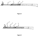
Figure 4 . It is a side perspective view of the open position of the locking channel and the eccentric bearing assembly developed by the current invention. -
Figure 5 . It is a side perspective view of the closed position of the locking channel and eccentric roller assembly developed by the current invention. -
- 1. Semi trailer vehicle
- 2. Locking channel
- 3. First platform
- 4. Second platform
- 5. Eccentric bearing assembly
- 6. Locking mechanism
- The drawings do not necessarily have to be scaled and the details that are not necessary to understand the current invention may be omitted. Furthermore, the elements which are at least substantially identical or have at least substantially identical functions are indicated by the same number.
- In this detailed description, a structure for the use of movable carrier platforms in semi-trey vehicles used for the purpose of carrying load according to the invention and providing the positioning of the platform, is explained only for a better understanding of the subject and without any limiting effects.
- The current invention, is related to the platform assembly found in the semi-trailer vehicles (1) with telescopic function, which can be used for the carrying of goods and which can extend from the front and middle according to the load, includes at least one locking channel (2) in mentioned platform assembly and a linear movement within mentioned locking channel (2) and at least one eccentric bearing assembly (4) which provides movement of the first platform (3) to fulfill the purposes described above that sample views given in
Figure 1-5 . - The system developed by the current invention consists of a container type that the container-carrying semi-trailer vehicles (1) will carry and the platform assemblies that can extend from the front, center and rear depending on the length. Semi-trey vehicles (1) have a mainframe positioned on wheels and multiple platforms that provide forward and backward movement on the main frame. These platforms can be adjusted by telescopic opening on the main frame.
- In an exemplary of the current invention, there is a first platform (3) which can be moved in parallel with the vehicle, preferably in a telescopic vehicle, which forms the front region of the semi-trey vehicle (1) depends on the load it carries, A locking channel (2) is present along the first platform (3). In the system developed by the current invention, there is also a second platform (4) forming the body of the semi-trey vehicle (1) after the chassis area and forming the middle region of the semi-trey vehicle (1). Eccentric bearing assembly (5) of the lower parts of the second platform (4) is positioned in such a way that it is movable back and forth in the locking channel (2) by engaging the locking channel (2) in the first platform (3). This movement made by the eccentric bearing assembly (5), the movement and positioning of the first platform (3) is carried out, transferring to the first platform (3) via the locking channel (2) The eccentric bearing assembly (5) consists of bearings positioned on the second platform (4).
- In the current construct, the movement of the oppositely positioned bearings on the second platform (4) can be provided in a continuous plane with the locking channel (2) extending along the first platform (3), In this way, the bearings can be prevented from getting out of the their places even in cases caused by the slope of the surface or the weight of the load being carried. Therefore, more precise position adjustments can be made. In this system, where the positioning process can be done precisely, it is prevented from deforming the lock systems easily because the load on the lock systems is reduced.
- In an exemplary of the system developed by the current invention, a channel (2) with a locking feature is used. Thus, thanks to the locking channel structure (2) in the system, each eccentric bearing assembly (5) is classified and positioned separately. As the bearings are limited and the contact point is separate for each bearing, the safety of these platforms is ensured during the load carrying.
- The system developed by the present invention preferably comprises and a locking mechanism which is positioned on the second platform (4) (6) in which the first platform (3) is brought to a predetermined position and/or secured in its current position. The locking mechanism (6) is connected to the eccentric roller assembly (5) in the second platform (4), thus, the locking mechanism (6) is more stable to operate.
- With the bearing provided by the channel (2) with locking feature in the system developed by the current invention, the eccentric bearing assembly (5) is easily seated in the slot on the slot, thus, the position of the eccentric bearing assembly (5) is easily understood by the user. In this way, a platform structure can be developed that carrying can be done easily by a single person.
Claims (10)
- In the semi-trey vehicles with telescopic function (1), which can be used front and/or centered according to the load used in freight transport, the wheels are a structure comprising a main frame on which is positioned and a first platform (3) which provides forward and backward movement on the main frame and it includes;• at least one locking channel (2) extending along the first platform (3),• at least one second platform (4) associated with the first platform (3),• at least one eccentric bearing assembly (5) positioned on the second platform (4) in such a way that it can move forward and backward in the locking channel (2) on the first platform (3) and providing the movement of the first platform (3) with the movement within the locking channel (2).
- A construct satisying Demand 1, characterized as; including plurality of oppositely positioned bearings on the second platform (4) of the eccentric bearing assembly (5)
- A construct satisfying Demand 1, characterized as; a locking mechanism (6) positioned on the second platform (4) and enabling the first platform (3) to be fixed in its current position.
- A construct satisfying Demand 3, characterized as; being connected with the locking mechanism (6) with the eccentric roller assembly (5) positioned on the second platform (4).
- A construct satisfying Demand 1, characterized as; being positioned first platform (3) n the front region of the semi-trey vehicles (1).
- A construct satisfying Demand 1, characterized as; being positioned the second platform (4) in the middle region of the semi-trey vehicles (1).
- A construct satisfying Demand 1, characterized as; moving back and forth on the first platform (3) on the horizontal plane.
- A construct satisfying Demand 1, characterized as; moving back and forth on the second platform (4) on the horizontal plane.
- A construct satisfying Demand 1, characterized as; the mentioned eccentric bearing assembly (3) moving back and forth on the horizontal plane.
- A construct satisfying Demand 1, characterized as; eccentric bearing assembly (5) comprising a locking channel (2) separately classified.
Applications Claiming Priority (1)
| Application Number | Priority Date | Filing Date | Title |
|---|---|---|---|
| TR201720803 | 2017-12-19 |
Publications (2)
| Publication Number | Publication Date |
|---|---|
| EP3501951A1 true EP3501951A1 (en) | 2019-06-26 |
| EP3501951B1 EP3501951B1 (en) | 2020-04-08 |
Family
ID=63794319
Family Applications (1)
| Application Number | Title | Priority Date | Filing Date |
|---|---|---|---|
| EP18198720.7A Active EP3501951B1 (en) | 2017-12-19 | 2018-10-04 | Construction of a moving platform developed for semi trails |
Country Status (1)
| Country | Link |
|---|---|
| EP (1) | EP3501951B1 (en) |
Citations (4)
| Publication number | Priority date | Publication date | Assignee | Title |
|---|---|---|---|---|
| JPS59192477U (en) * | 1983-06-10 | 1984-12-20 | 東洋車輛工業株式会社 | telescopic trailer |
| JPH07277060A (en) * | 1994-04-13 | 1995-10-24 | Fujita Jidosha Kogyo Kk | Trailer |
| JP2013103623A (en) * | 2011-11-14 | 2013-05-30 | Nippon Fruehauf Co Ltd | Side bumper of semi-trailer |
| EP3093220A1 (en) * | 2015-05-12 | 2016-11-16 | System Trailers Fahrzeugbau GmbH | Expandable vehicle trailer |
-
2018
- 2018-10-04 EP EP18198720.7A patent/EP3501951B1/en active Active
Patent Citations (4)
| Publication number | Priority date | Publication date | Assignee | Title |
|---|---|---|---|---|
| JPS59192477U (en) * | 1983-06-10 | 1984-12-20 | 東洋車輛工業株式会社 | telescopic trailer |
| JPH07277060A (en) * | 1994-04-13 | 1995-10-24 | Fujita Jidosha Kogyo Kk | Trailer |
| JP2013103623A (en) * | 2011-11-14 | 2013-05-30 | Nippon Fruehauf Co Ltd | Side bumper of semi-trailer |
| EP3093220A1 (en) * | 2015-05-12 | 2016-11-16 | System Trailers Fahrzeugbau GmbH | Expandable vehicle trailer |
Also Published As
| Publication number | Publication date |
|---|---|
| EP3501951B1 (en) | 2020-04-08 |
Similar Documents
| Publication | Publication Date | Title |
|---|---|---|
| US3906870A (en) | Retractable cargo restraint and center guide for cargo compartments | |
| US4580805A (en) | Extendable container chassis for trucks | |
| US3374010A (en) | Coupleable chassis | |
| US4950123A (en) | Retractable bed for truck | |
| US5513941A (en) | Rolling cargo apparatus | |
| EP3623244A1 (en) | A method of loading an automobile semi-trailer on a flatcar | |
| RU185241U1 (en) | Flat car for the transport of automotive semi-trailers and large containers | |
| US3984117A (en) | Locking device for freight carts | |
| US2756073A (en) | Transportable half flat-carload container convertible to semi-trailer | |
| CN105291902A (en) | Seat track assembly having load absorption features | |
| US11167849B2 (en) | Modular cargo handling system | |
| RU2019100503A (en) | IMPROVED SEMI-TRAILER | |
| SE7603304L (en) | SYSTEMS FOR HANDLING GOODS ON LOAD CARRIERS FOR COMBINED RAIL AND ROAD TRANSPORT. | |
| WO2008030786A2 (en) | Attachment device for moving cargo containers | |
| US8231315B2 (en) | Stackable armored vehicle | |
| EP3501951B1 (en) | Construction of a moving platform developed for semi trails | |
| US7673889B2 (en) | Direct loading apparatus for pallet related systems | |
| US11434069B2 (en) | Corner fittings for modular containers | |
| JPS61501265A (en) | Device for transporting loading units between two carriers | |
| US3168876A (en) | Freight transportation systems | |
| US10843635B2 (en) | Carrier assembly for transporting hand trucks | |
| EP3763594B1 (en) | Lifting support equipment for loading processes in the railway transport | |
| CN110949422B (en) | Locking device and vehicle with same | |
| CN110139779B (en) | Transportation platform | |
| EP3505419A1 (en) | Mobile platform for transport systems |
Legal Events
| Date | Code | Title | Description |
|---|---|---|---|
| PUAI | Public reference made under article 153(3) epc to a published international application that has entered the european phase |
Free format text: ORIGINAL CODE: 0009012 |
|
| STAA | Information on the status of an ep patent application or granted ep patent |
Free format text: STATUS: THE APPLICATION HAS BEEN PUBLISHED |
|
| AK | Designated contracting states |
Kind code of ref document: A1 Designated state(s): AL AT BE BG CH CY CZ DE DK EE ES FI FR GB GR HR HU IE IS IT LI LT LU LV MC MK MT NL NO PL PT RO RS SE SI SK SM TR |
|
| AX | Request for extension of the european patent |
Extension state: BA ME |
|
| STAA | Information on the status of an ep patent application or granted ep patent |
Free format text: STATUS: REQUEST FOR EXAMINATION WAS MADE |
|
| 17P | Request for examination filed |
Effective date: 20190620 |
|
| RBV | Designated contracting states (corrected) |
Designated state(s): AL AT BE BG CH CY CZ DE DK EE ES FI FR GB GR HR HU IE IS IT LI LT LU LV MC MK MT NL NO PL PT RO RS SE SI SK SM TR |
|
| GRAP | Despatch of communication of intention to grant a patent |
Free format text: ORIGINAL CODE: EPIDOSNIGR1 |
|
| STAA | Information on the status of an ep patent application or granted ep patent |
Free format text: STATUS: GRANT OF PATENT IS INTENDED |
|
| GRAS | Grant fee paid |
Free format text: ORIGINAL CODE: EPIDOSNIGR3 |
|
| INTG | Intention to grant announced |
Effective date: 20200129 |
|
| GRAA | (expected) grant |
Free format text: ORIGINAL CODE: 0009210 |
|
| STAA | Information on the status of an ep patent application or granted ep patent |
Free format text: STATUS: THE PATENT HAS BEEN GRANTED |
|
| AK | Designated contracting states |
Kind code of ref document: B1 Designated state(s): AL AT BE BG CH CY CZ DE DK EE ES FI FR GB GR HR HU IE IS IT LI LT LU LV MC MK MT NL NO PL PT RO RS SE SI SK SM TR |
|
| REG | Reference to a national code |
Ref country code: CH Ref legal event code: EP Ref country code: AT Ref legal event code: REF Ref document number: 1254018 Country of ref document: AT Kind code of ref document: T Effective date: 20200415 |
|
| REG | Reference to a national code |
Ref country code: DE Ref legal event code: R096 Ref document number: 602018003625 Country of ref document: DE |
|
| REG | Reference to a national code |
Ref country code: IE Ref legal event code: FG4D |
|
| REG | Reference to a national code |
Ref country code: NL Ref legal event code: FP |
|
| REG | Reference to a national code |
Ref country code: LT Ref legal event code: MG4D |
|
| PG25 | Lapsed in a contracting state [announced via postgrant information from national office to epo] |
Ref country code: FI Free format text: LAPSE BECAUSE OF FAILURE TO SUBMIT A TRANSLATION OF THE DESCRIPTION OR TO PAY THE FEE WITHIN THE PRESCRIBED TIME-LIMIT Effective date: 20200408 Ref country code: PT Free format text: LAPSE BECAUSE OF FAILURE TO SUBMIT A TRANSLATION OF THE DESCRIPTION OR TO PAY THE FEE WITHIN THE PRESCRIBED TIME-LIMIT Effective date: 20200817 Ref country code: LT Free format text: LAPSE BECAUSE OF FAILURE TO SUBMIT A TRANSLATION OF THE DESCRIPTION OR TO PAY THE FEE WITHIN THE PRESCRIBED TIME-LIMIT Effective date: 20200408 Ref country code: NO Free format text: LAPSE BECAUSE OF FAILURE TO SUBMIT A TRANSLATION OF THE DESCRIPTION OR TO PAY THE FEE WITHIN THE PRESCRIBED TIME-LIMIT Effective date: 20200708 Ref country code: GR Free format text: LAPSE BECAUSE OF FAILURE TO SUBMIT A TRANSLATION OF THE DESCRIPTION OR TO PAY THE FEE WITHIN THE PRESCRIBED TIME-LIMIT Effective date: 20200709 Ref country code: IS Free format text: LAPSE BECAUSE OF FAILURE TO SUBMIT A TRANSLATION OF THE DESCRIPTION OR TO PAY THE FEE WITHIN THE PRESCRIBED TIME-LIMIT Effective date: 20200808 Ref country code: SE Free format text: LAPSE BECAUSE OF FAILURE TO SUBMIT A TRANSLATION OF THE DESCRIPTION OR TO PAY THE FEE WITHIN THE PRESCRIBED TIME-LIMIT Effective date: 20200408 |
|
| REG | Reference to a national code |
Ref country code: AT Ref legal event code: MK05 Ref document number: 1254018 Country of ref document: AT Kind code of ref document: T Effective date: 20200408 |
|
| PG25 | Lapsed in a contracting state [announced via postgrant information from national office to epo] |
Ref country code: BG Free format text: LAPSE BECAUSE OF FAILURE TO SUBMIT A TRANSLATION OF THE DESCRIPTION OR TO PAY THE FEE WITHIN THE PRESCRIBED TIME-LIMIT Effective date: 20200708 Ref country code: HR Free format text: LAPSE BECAUSE OF FAILURE TO SUBMIT A TRANSLATION OF THE DESCRIPTION OR TO PAY THE FEE WITHIN THE PRESCRIBED TIME-LIMIT Effective date: 20200408 Ref country code: RS Free format text: LAPSE BECAUSE OF FAILURE TO SUBMIT A TRANSLATION OF THE DESCRIPTION OR TO PAY THE FEE WITHIN THE PRESCRIBED TIME-LIMIT Effective date: 20200408 Ref country code: LV Free format text: LAPSE BECAUSE OF FAILURE TO SUBMIT A TRANSLATION OF THE DESCRIPTION OR TO PAY THE FEE WITHIN THE PRESCRIBED TIME-LIMIT Effective date: 20200408 |
|
| PG25 | Lapsed in a contracting state [announced via postgrant information from national office to epo] |
Ref country code: AL Free format text: LAPSE BECAUSE OF FAILURE TO SUBMIT A TRANSLATION OF THE DESCRIPTION OR TO PAY THE FEE WITHIN THE PRESCRIBED TIME-LIMIT Effective date: 20200408 |
|
| REG | Reference to a national code |
Ref country code: DE Ref legal event code: R097 Ref document number: 602018003625 Country of ref document: DE |
|
| PG25 | Lapsed in a contracting state [announced via postgrant information from national office to epo] |
Ref country code: DK Free format text: LAPSE BECAUSE OF FAILURE TO SUBMIT A TRANSLATION OF THE DESCRIPTION OR TO PAY THE FEE WITHIN THE PRESCRIBED TIME-LIMIT Effective date: 20200408 Ref country code: AT Free format text: LAPSE BECAUSE OF FAILURE TO SUBMIT A TRANSLATION OF THE DESCRIPTION OR TO PAY THE FEE WITHIN THE PRESCRIBED TIME-LIMIT Effective date: 20200408 Ref country code: SM Free format text: LAPSE BECAUSE OF FAILURE TO SUBMIT A TRANSLATION OF THE DESCRIPTION OR TO PAY THE FEE WITHIN THE PRESCRIBED TIME-LIMIT Effective date: 20200408 Ref country code: EE Free format text: LAPSE BECAUSE OF FAILURE TO SUBMIT A TRANSLATION OF THE DESCRIPTION OR TO PAY THE FEE WITHIN THE PRESCRIBED TIME-LIMIT Effective date: 20200408 Ref country code: ES Free format text: LAPSE BECAUSE OF FAILURE TO SUBMIT A TRANSLATION OF THE DESCRIPTION OR TO PAY THE FEE WITHIN THE PRESCRIBED TIME-LIMIT Effective date: 20200408 Ref country code: CZ Free format text: LAPSE BECAUSE OF FAILURE TO SUBMIT A TRANSLATION OF THE DESCRIPTION OR TO PAY THE FEE WITHIN THE PRESCRIBED TIME-LIMIT Effective date: 20200408 Ref country code: RO Free format text: LAPSE BECAUSE OF FAILURE TO SUBMIT A TRANSLATION OF THE DESCRIPTION OR TO PAY THE FEE WITHIN THE PRESCRIBED TIME-LIMIT Effective date: 20200408 Ref country code: IT Free format text: LAPSE BECAUSE OF FAILURE TO SUBMIT A TRANSLATION OF THE DESCRIPTION OR TO PAY THE FEE WITHIN THE PRESCRIBED TIME-LIMIT Effective date: 20200408 |
|
| PLBE | No opposition filed within time limit |
Free format text: ORIGINAL CODE: 0009261 |
|
| STAA | Information on the status of an ep patent application or granted ep patent |
Free format text: STATUS: NO OPPOSITION FILED WITHIN TIME LIMIT |
|
| PG25 | Lapsed in a contracting state [announced via postgrant information from national office to epo] |
Ref country code: SK Free format text: LAPSE BECAUSE OF FAILURE TO SUBMIT A TRANSLATION OF THE DESCRIPTION OR TO PAY THE FEE WITHIN THE PRESCRIBED TIME-LIMIT Effective date: 20200408 Ref country code: PL Free format text: LAPSE BECAUSE OF FAILURE TO SUBMIT A TRANSLATION OF THE DESCRIPTION OR TO PAY THE FEE WITHIN THE PRESCRIBED TIME-LIMIT Effective date: 20200408 |
|
| 26N | No opposition filed |
Effective date: 20210112 |
|
| PG25 | Lapsed in a contracting state [announced via postgrant information from national office to epo] |
Ref country code: SI Free format text: LAPSE BECAUSE OF FAILURE TO SUBMIT A TRANSLATION OF THE DESCRIPTION OR TO PAY THE FEE WITHIN THE PRESCRIBED TIME-LIMIT Effective date: 20200408 |
|
| PG25 | Lapsed in a contracting state [announced via postgrant information from national office to epo] |
Ref country code: MC Free format text: LAPSE BECAUSE OF FAILURE TO SUBMIT A TRANSLATION OF THE DESCRIPTION OR TO PAY THE FEE WITHIN THE PRESCRIBED TIME-LIMIT Effective date: 20200408 Ref country code: LU Free format text: LAPSE BECAUSE OF NON-PAYMENT OF DUE FEES Effective date: 20201004 |
|
| PG25 | Lapsed in a contracting state [announced via postgrant information from national office to epo] |
Ref country code: FR Free format text: LAPSE BECAUSE OF NON-PAYMENT OF DUE FEES Effective date: 20201031 |
|
| PG25 | Lapsed in a contracting state [announced via postgrant information from national office to epo] |
Ref country code: IE Free format text: LAPSE BECAUSE OF NON-PAYMENT OF DUE FEES Effective date: 20201004 |
|
| REG | Reference to a national code |
Ref country code: CH Ref legal event code: PL |
|
| PG25 | Lapsed in a contracting state [announced via postgrant information from national office to epo] |
Ref country code: TR Free format text: LAPSE BECAUSE OF FAILURE TO SUBMIT A TRANSLATION OF THE DESCRIPTION OR TO PAY THE FEE WITHIN THE PRESCRIBED TIME-LIMIT Effective date: 20200408 Ref country code: MT Free format text: LAPSE BECAUSE OF FAILURE TO SUBMIT A TRANSLATION OF THE DESCRIPTION OR TO PAY THE FEE WITHIN THE PRESCRIBED TIME-LIMIT Effective date: 20200408 Ref country code: CY Free format text: LAPSE BECAUSE OF FAILURE TO SUBMIT A TRANSLATION OF THE DESCRIPTION OR TO PAY THE FEE WITHIN THE PRESCRIBED TIME-LIMIT Effective date: 20200408 |
|
| PG25 | Lapsed in a contracting state [announced via postgrant information from national office to epo] |
Ref country code: MK Free format text: LAPSE BECAUSE OF FAILURE TO SUBMIT A TRANSLATION OF THE DESCRIPTION OR TO PAY THE FEE WITHIN THE PRESCRIBED TIME-LIMIT Effective date: 20200408 |
|
| PG25 | Lapsed in a contracting state [announced via postgrant information from national office to epo] |
Ref country code: LI Free format text: LAPSE BECAUSE OF NON-PAYMENT OF DUE FEES Effective date: 20211031 Ref country code: CH Free format text: LAPSE BECAUSE OF NON-PAYMENT OF DUE FEES Effective date: 20211031 |
|
| GBPC | Gb: european patent ceased through non-payment of renewal fee |
Effective date: 20221004 |
|
| PG25 | Lapsed in a contracting state [announced via postgrant information from national office to epo] |
Ref country code: GB Free format text: LAPSE BECAUSE OF NON-PAYMENT OF DUE FEES Effective date: 20221004 |
|
| PGFP | Annual fee paid to national office [announced via postgrant information from national office to epo] |
Ref country code: NL Payment date: 20250925 Year of fee payment: 8 |
|
| PGFP | Annual fee paid to national office [announced via postgrant information from national office to epo] |
Ref country code: DE Payment date: 20251023 Year of fee payment: 8 |
|
| PGFP | Annual fee paid to national office [announced via postgrant information from national office to epo] |
Ref country code: BE Payment date: 20251021 Year of fee payment: 8 |