EP3501894B1 - A device for suspension of a lamp in a vehicle - Google Patents
A device for suspension of a lamp in a vehicle Download PDFInfo
- Publication number
- EP3501894B1 EP3501894B1 EP17208551.6A EP17208551A EP3501894B1 EP 3501894 B1 EP3501894 B1 EP 3501894B1 EP 17208551 A EP17208551 A EP 17208551A EP 3501894 B1 EP3501894 B1 EP 3501894B1
- Authority
- EP
- European Patent Office
- Prior art keywords
- lamp
- axis
- vehicle
- guiding
- parallel
- Prior art date
- Legal status (The legal status is an assumption and is not a legal conclusion. Google has not performed a legal analysis and makes no representation as to the accuracy of the status listed.)
- Active
Links
Images




Classifications
-
- B—PERFORMING OPERATIONS; TRANSPORTING
- B60—VEHICLES IN GENERAL
- B60Q—ARRANGEMENT OF SIGNALLING OR LIGHTING DEVICES, THE MOUNTING OR SUPPORTING THEREOF OR CIRCUITS THEREFOR, FOR VEHICLES IN GENERAL
- B60Q1/00—Arrangement of optical signalling or lighting devices, the mounting or supporting thereof or circuits therefor
- B60Q1/02—Arrangement of optical signalling or lighting devices, the mounting or supporting thereof or circuits therefor the devices being primarily intended to illuminate the way ahead or to illuminate other areas of way or environments
- B60Q1/04—Arrangement of optical signalling or lighting devices, the mounting or supporting thereof or circuits therefor the devices being primarily intended to illuminate the way ahead or to illuminate other areas of way or environments the devices being headlights
- B60Q1/0491—Shock absorbing devices therefor
-
- B—PERFORMING OPERATIONS; TRANSPORTING
- B60—VEHICLES IN GENERAL
- B60Q—ARRANGEMENT OF SIGNALLING OR LIGHTING DEVICES, THE MOUNTING OR SUPPORTING THEREOF OR CIRCUITS THEREFOR, FOR VEHICLES IN GENERAL
- B60Q1/00—Arrangement of optical signalling or lighting devices, the mounting or supporting thereof or circuits therefor
- B60Q1/02—Arrangement of optical signalling or lighting devices, the mounting or supporting thereof or circuits therefor the devices being primarily intended to illuminate the way ahead or to illuminate other areas of way or environments
- B60Q1/04—Arrangement of optical signalling or lighting devices, the mounting or supporting thereof or circuits therefor the devices being primarily intended to illuminate the way ahead or to illuminate other areas of way or environments the devices being headlights
- B60Q1/0408—Arrangement of optical signalling or lighting devices, the mounting or supporting thereof or circuits therefor the devices being primarily intended to illuminate the way ahead or to illuminate other areas of way or environments the devices being headlights built into the vehicle body, e.g. details concerning the mounting of the headlamps on the vehicle body
- B60Q1/0416—Arrangement of optical signalling or lighting devices, the mounting or supporting thereof or circuits therefor the devices being primarily intended to illuminate the way ahead or to illuminate other areas of way or environments the devices being headlights built into the vehicle body, e.g. details concerning the mounting of the headlamps on the vehicle body the housing being mounted on the vehicle body using rails
-
- B—PERFORMING OPERATIONS; TRANSPORTING
- B60—VEHICLES IN GENERAL
- B60R—VEHICLES, VEHICLE FITTINGS, OR VEHICLE PARTS, NOT OTHERWISE PROVIDED FOR
- B60R21/00—Arrangements or fittings on vehicles for protecting or preventing injuries to occupants or pedestrians in case of accidents or other traffic risks
- B60R21/34—Protecting non-occupants of a vehicle, e.g. pedestrians
-
- F—MECHANICAL ENGINEERING; LIGHTING; HEATING; WEAPONS; BLASTING
- F21—LIGHTING
- F21S—NON-PORTABLE LIGHTING DEVICES; SYSTEMS THEREOF; VEHICLE LIGHTING DEVICES SPECIALLY ADAPTED FOR VEHICLE EXTERIORS
- F21S41/00—Illuminating devices specially adapted for vehicle exteriors, e.g. headlamps
- F21S41/10—Illuminating devices specially adapted for vehicle exteriors, e.g. headlamps characterised by the light source
- F21S41/19—Attachment of light sources or lamp holders
- F21S41/192—Details of lamp holders, terminals or connectors
-
- F—MECHANICAL ENGINEERING; LIGHTING; HEATING; WEAPONS; BLASTING
- F21—LIGHTING
- F21S—NON-PORTABLE LIGHTING DEVICES; SYSTEMS THEREOF; VEHICLE LIGHTING DEVICES SPECIALLY ADAPTED FOR VEHICLE EXTERIORS
- F21S41/00—Illuminating devices specially adapted for vehicle exteriors, e.g. headlamps
- F21S41/10—Illuminating devices specially adapted for vehicle exteriors, e.g. headlamps characterised by the light source
- F21S41/19—Attachment of light sources or lamp holders
- F21S41/196—Wire spring attachments
-
- B—PERFORMING OPERATIONS; TRANSPORTING
- B60—VEHICLES IN GENERAL
- B60R—VEHICLES, VEHICLE FITTINGS, OR VEHICLE PARTS, NOT OTHERWISE PROVIDED FOR
- B60R21/00—Arrangements or fittings on vehicles for protecting or preventing injuries to occupants or pedestrians in case of accidents or other traffic risks
- B60R21/34—Protecting non-occupants of a vehicle, e.g. pedestrians
- B60R2021/343—Protecting non-occupants of a vehicle, e.g. pedestrians using deformable body panel, bodywork or components
Definitions
- FR2901202 seems to disclose a device in which the lamp is displaceable in the horizontal direction (in parallel with an X-axis) in case of a collision with a leg of a pedestrian or thatthe lamp can be pivoted in case of a collision with a head of a pedestrian.
- DE3802104 seems to disclose an arrangement of a vehicle lighting unit which has a housing supported on the body of the vehicle by an elastic support, for receiving at least one lamp. In the event of an impact loading acting from the outside, the housing can deflect with each edge region into a vehicle body-side free space.
- EP1346874 seems to disclose a mounting of a lighting unit on a vehicle body part.
- the optical block is guided in case of frontal shock by forward and rear mechanisms.
- the forward mechanism uses a peg and groove inclined at a small angle of 5-20 degrees toallow the lighting block to move backwards while the rear mechanism consists of a pivoted crank which displaces the lighting block sideways
- An objective of the invention is to provide a device for suspension of a lamp in a vehicle, which device will reduce pedestrian injuries in case of a head impact to the lamp.
- the invention is based on the insight that by such a device, energy can be absorbed during the impact even if the space close to the lamp is limited, particularly for a lamp mounted on a position in the hood and/or the front wheel fender area where the lamp has a major part of an exterior surface facing upwardly with a surface normal having a major direction component in parallel with the Z-axis. If the space available for movement of the lamp in the Z-direction is limited, energy can be absorbed by the movement in the X-direction and the pivot motion. This in turn will improve the pedestrian safety in case of an impact.
- the guiding means is arranged for guiding the lamp such that said movement direction has a movement direction component in parallel to the Z-axis.
- the energy absorption can be further improved in case there is a space available for movement of the lamp in the Z-direction.
- the guiding means comprises a first guide rail mechanism arranged for connecting a front end of the lamp to the vehicle and a second guide rail mechanism arranged for connecting a rear end of the lamp to the vehicle.
- the movement and the pivot motion of the lamp can be achieved, for example by guiding the lamp in the movement direction by means of the first guide rail mechanism and guiding the lamp to pivot by means of the second guide rail mechanism.
- the guiding means comprises a pivot arm for guiding the lamp to pivot about the pivot axis
- the pivot arm comprises a first arm unit and a second arm unit, a first end of the first arm unit being pivotally connectable to the vehicle, a second end of the first arm unit and a first end of the second arm unit being pivotally connected to each other, the second arm unit constituting a guide rail mechanism for guiding the lamp to move from a second end of the second arm unit towards the first end of the second arm unit.
- the lamp 2 is suitably arranged such that an exterior surface 5 of the lamp is substantially flush with an exterior surface of the hood 3 and the front wheel fender 4 of the vehicle 1.
- the lamp 2 is suspended in the vehicle 1 by means of a vehicle lamp suspension device 7 that will be described in detail hereinbelow.
- transverse is meant a direction that can deviate from a direction perpendicular to the X-axis and Z-axis. The deviation can be within ⁇ 30°, preferably ⁇ 20° and often within ⁇ 10° from a direction perpendicular to the current axis.
- the guiding means 8 is arranged for guiding the lamp 2 to pivot about the pivot axis for giving a rear part of the lamp 2 a lower position in the second position of the lamp after an impact in comparison to the first position of the lamp before impact, and preferably for giving a front part of the lamp a higher position in the second position in comparison to the first position.
- the pin 32 is moved inwards and downwards, and the pin 31 is moved inwards and pivoted relative to the flange unit 27.
- the lamp 2 will pivot counter clockwise (when seen in the Y-axis direction) about the pivot axis 33 extending through the centre of the pin 31.
- an energy absorber in form of a spring arranged such as the first and second energy absorbers 9a, 9b in Fig. 2 will create a counterforce only when the lamp causing the spring to be compressed
- the energy absorber could be arranged for providing a counterforce when the energy absorber is stretched.
- the energy absorber can be any kind of metal spring, foam, plastic component, etc., that preferably has a non-linear spring constant.
- a spring can have a non-linear spring constant increasing with increased compression of the spring.
- the lamp suspension device or any other part of the vehicle may comprise an attachment component for mechanical connection of the lamp to the vehicle.
- an attachment component can be used for connecting the lamp to the vehicle and keeping the lamp in an intended position, for example the first position mentioned above, in absence of any impact.
- the lamp is releasable from this connection to the vehicle in case of an impact.
- the lamp has preferably a break off feature withstanding static loads.
- such an attachment component can be broken in case of an impact and thereafter the movement of the lamp during impact is mainly determined by the guiding means and the energy absorber.
- the guiding means can be used also for connecting the lamp to the vehicle and keeping the lamp in the intended first position.
- Fig. 3 shows a variant of a guiding means for the vehicle lamp suspension device illustrated in Fig. 2 .
- the vehicle lamp suspension device with such a guiding means is according to the invention.
Landscapes
- Engineering & Computer Science (AREA)
- Mechanical Engineering (AREA)
- General Engineering & Computer Science (AREA)
- Lighting Device Outwards From Vehicle And Optical Signal (AREA)
Description
- The invention relates to a device for suspension of a lamp in a vehicle, and a vehicle comprising such a lamp suspension device.
- During a collision of a vehicle with a pedestrian, the pedestrian often collides with the head on the hood and/or the fender of the vehicle. Further, any lamp arranged in the front of the vehicle may constitute a relative hard structure. To mitigate injuries to pedestrians, vehicles are usually adapted to yield in response to forces generated by a pedestrian impact. For example, the vehicle may be equipped with a pedestrian air bag or a device for changing the inclination angle of the hood, etc.
-
FR2901202 DE3802104 seems to disclose an arrangement of a vehicle lighting unit which has a housing supported on the body of the vehicle by an elastic support, for receiving at least one lamp. In the event of an impact loading acting from the outside, the housing can deflect with each edge region into a vehicle body-side free space.EP1346874 seems to disclose a mounting of a lighting unit on a vehicle body part. The optical block is guided in case of frontal shock by forward and rear mechanisms. The forward mechanism uses a peg and groove inclined at a small angle of 5-20 degrees toallow the lighting block to move backwards while the rear mechanism consists of a pivoted crank which displaces the lighting block sideways - An objective of the invention is to provide a device for suspension of a lamp in a vehicle, which device will reduce pedestrian injuries in case of a head impact to the lamp.
- The objective is achieved by a device for suspension of a lamp in a vehicle according to
claim 1. - The invention is based on the insight that by such a device, energy can be absorbed during the impact even if the space close to the lamp is limited, particularly for a lamp mounted on a position in the hood and/or the front wheel fender area where the lamp has a major part of an exterior surface facing upwardly with a surface normal having a major direction component in parallel with the Z-axis. If the space available for movement of the lamp in the Z-direction is limited, energy can be absorbed by the movement in the X-direction and the pivot motion. This in turn will improve the pedestrian safety in case of an impact.
- The directions and axes used herein, i.e. the X-axis, Y-axis and the Z-axis, constitute a cartesian coordinate system arranged relative to a vehicle such that the X-axis is in parallel with the horizontal longitudinal extension of the vehicle, the Y-axis is in parallel with the horizontal lateral extension of the vehicle, thus being perpendicular to the X-axis, and the Z-axis is in parallel with a vertical extension of the vehicle, thus being perpendicular to the X-axis and the Y-axis.
- According to the invention, the guiding means is arranged for guiding the lamp such that said movement direction has a movement direction component in parallel to the Z-axis. Hereby, the energy absorption can be further improved in case there is a space available for movement of the lamp in the Z-direction.
- According to another embodiment, the pivot axis is substantially perpendicular to the X-axis, and preferably the pivot axis is substantially perpendicular to the Z-axis. Hereby, the energy absorption can be further improved since the orientation of the pivot axis relative to an impact direction is often favourable.
- According to a further embodiment, the guiding means comprises a first guide rail mechanism arranged for connecting a front end of the lamp to the vehicle and a second guide rail mechanism arranged for connecting a rear end of the lamp to the vehicle. Herby, the movement and the pivot motion of the lamp can be achieved, for example by guiding the lamp in the movement direction by means of the first guide rail mechanism and guiding the lamp to pivot by means of the second guide rail mechanism.
- According to a further embodiment, the first guide rail mechanism comprises a first guide portion for guiding the lamp in said movement direction having a movement direction component in parallel with the X-axis and a movement direction component in parallel with the Z-axis, and a second guide portion for subsequently guiding the lamp in said movement direction being substantially in parallel with the X-axis. Hereby, the space available for movement of the lamp can be efficiently used for energy absorption if the space available in the X-direction is larger than the space available in the Z-direction. According to a further embodiment, the guiding means comprises a pivot arm for guiding the lamp to pivot about the pivot axis, and preferably the pivot arm comprises a first arm unit and a second arm unit, a first end of the first arm unit being pivotally connectable to the vehicle, a second end of the first arm unit and a first end of the second arm unit being pivotally connected to each other, the second arm unit constituting a guide rail mechanism for guiding the lamp to move from a second end of the second arm unit towards the first end of the second arm unit. Hereby, a translation motion of the lamp can be used for achieving a pivot motion of the lamp.
- According to another aspect of the invention, a further objective is to provide a vehicle, which vehicle will reduce pedestrian injuries in case of a head impact to a vehicle lamp. This objective is achieved by a vehicle provided with a device according to the invention. The advantages of the vehicle are the same as the advantages already discussed hereinabove with reference to the embodiments of the device.
- Further advantages and advantageous features of the invention are disclosed in the following description and in the dependent claims.
- With reference to the appended drawings, below follows a more detailed description of embodiments of the invention cited as examples.
- In the drawings:
-
Fig. 1 is a perspective front view of a vehicle, -
Fig. 1b is a side view of the vehicle illustrated inFig. 1 , -
Fig. 2 is a side view of one embodiment of a device for suspension of a lamp in a vehicle not according to the invention and a lamp seen in a direction in parallel to the Y-axis, -
Fig. 2b shows the lamp inFig. 2 in case of an impact in the front part of the lamp, -
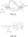
Fig. 2c is a front view of the device illustrated inFig. 2 , -
Fig. 2d indicates the orientation of the lamp inFigs. 2 and 2b before and after impact, respectively, -
Fig. 3 is a variant of a guiding means of a device for suspension of a lamp in a vehicle according to the invention, -
Fig. 4a shows a blocking component, -
Fig. 4b shows a variant of a blocking component, -
Fig. 5 is a variant of a device for suspension of a lamp in a vehicle not according to the invention and a lamp seen in a direction in parallel to the Y-axis, and -
Fig. 5b shows the lamp inFig. 5 in case of an impact in the front part of the lamp. -
Fig. 1 is a perspective view of avehicle 1 andFig. 1b shows thevehicle 1 in a side view. A cartesian coordinate system having axes X, Y and Z is also shown. Thevehicle 1 and the individual components will be described herein with reference to this coordinate system. Thevehicle 1 has twosupplement lamps 2 for daytime running light (DRL) arranged in the hood and front wheel fender area of thevehicle 1. Onesuch lamp 2 is arranged on the left side of thevehicle 1 at the boundary between thehood 3 and the adjacentfront wheel fender 4. In the same way theother lamp 2 is arranged on the right side of the vehicle. - As can be seen in
Fig. 1b , thelamp 2 can be arranged such that a major part of anexterior surface 5 of the lamp faces upwardly with a surface normal 6 having a major direction component 6a in parallel with the Z-axis. This does not necessarily mean that thesurface 5 of the lamp is completely horizontal. InFig. 1b , where thelamp 2 on the right side of thevehicle 1 is illustrated, thelamp 2 is somewhat inclined relative to the X-axis, but the surface normal 6 of thelamp 2 has a larger component 6a in a direction in parallel with the Z-axis than acomponent 6b in a direction in parallel with the X-axis. Thesurface 5 can also be somewhat inclined relative to the Y-axis. - For example, the
exterior surface 5 of the lamp can be inclined relative to the X-axis with an angle α selected in the range 0≤α<45°, preferably 0≤α≤30°, and relative to the Y-axis with an angle β selected in the range 0≤β<45°, preferably 0≤β≤30°. If the exterior surface of thelamp 2 is inclined relative to the X-axis, preferably the rear part of the exterior surface of the lamp is arranged at a higher level than the front part of the exterior surface of thelamp 2, and if the exterior surface of thelamp 2 is inclined relative to the Y-axis, preferably the inner part of the exterior surface of thelamp 2 is arranged at a higher level than the outer part of the exterior surface of thelamp 2. - Although the exterior surface of the lamp does not need to be horizontal, preferably the projected surface of the lamp seen in a direction in parallel with the Z-axis has however a considerable area that could be subject to an impact with an object.
- Further, the
lamp 2 is suitably arranged such that anexterior surface 5 of the lamp is substantially flush with an exterior surface of thehood 3 and thefront wheel fender 4 of thevehicle 1. - The
lamp 2 is suspended in thevehicle 1 by means of a vehiclelamp suspension device 7 that will be described in detail hereinbelow. -
Fig. 2 shows adevice 7 for suspension of thelamp 2 in thevehicle 1. Thedevice 7 comprises a guiding means 8 for guiding thelamp 2 to move relative to thevehicle 1 from a first position to a second position in case of an impact between the lamp and an object. Thedevice 7 also comprises at least oneenergy absorber - The guiding means 8 is arranged for guiding the lamp to move inwardly in a
movement direction 10 having a movement direction component in parallel with the X-axis while the movement of the lamp being counteracted by said energy absorber, and to pivot about an axis being transverse relative to the X-axis and the Z-axis, while the pivot motion being counteracted by one further energy absorber, giving the lamp a different orientation in the second position in comparison to the first position. The pivot axis is a geometrical axis that can be situated on the lamp or at a distance from the lamp. - The expression "movement direction" used herein refers to the resulting translation motion direction, whereas "movement direction component" is a component contributing to the "movement direction".
- By "transverse" is meant a direction that can deviate from a direction perpendicular to the X-axis and Z-axis. The deviation can be within ±30°, preferably ±20° and often within ±10° from a direction perpendicular to the current axis.
- The guiding means is suitably arranged for guiding the lamp to move such that the movement direction component in parallel with the X-axis is considerably larger than any movement direction component in parallel with the Y-axis, and preferably the guiding means is arranged for guiding the lamp to move such that the movement direction is substantially in the XZ-plane.
- In the example embodiment illustrated in
Fig. 2 , the guiding means 8 comprises a firstguide rail mechanism 20 arranged for connecting afront end 21 of thelamp 2 to thevehicle 1 and a secondguide rail mechanism 22 arranged for connecting arear end 23 of the lamp to thevehicle 1. The firstguide rail mechanism 20 can be arranged for guiding thelamp 2 to move with amovement direction 10 having a movement direction component in parallel with the X-axis that is considerably larger than a movement direction component in parallel to the Z-axis, and preferably for guiding the lamp to move inwardly such that themovement direction 10 is substantially in parallel with the X-axis. - As an example, the guiding means can comprise two said first guide rail mechanisms arranged spaced apart from each other in the pivot axis direction, and one said second guide rail mechanism.
- The second
guide rail mechanism 22 is arranged for guiding thelamp 2 to move inwardly and downwardly in amovement direction 24 having amovement direction component 25 in parallel with the X-axis and amovement direction component 26 in parallel with the Z-axis. In case of an impact, the lamp will move inwards and pivot because the rear end of the lamp is moved downwards with themovement direction component 26. Here, thegeometrical pivot axis 33 is substantially perpendicular to the X-axis and the Z-axis, i.e. the pivot axis extends substantially in parallel with the Y-axis. - Thus, in the example embodiment illustrated in
Fig. 2 , the guiding means 8 is arranged for guiding thelamp 2 to pivot about the pivot axis for giving a rear part of the lamp 2 a lower position in the second position of the lamp after an impact in comparison to the first position of the lamp before impact, and preferably for giving a front part of the lamp a higher position in the second position in comparison to the first position. - Each said
guide rail mechanism flange unit slot pin lamp 2. Although eachflange unit vehicle 1 and receive thepin - Since the
pivot axis 33 of thelamp 2 is the centre of thepin 31, thepivot axis 33 will move with the translation motion in themovement direction 10. -
Fig. 2b shows thelamp 2 after an impact 70 (schematically illustrated inFig. 2 ) in the front part of thelamp 2 where the lamp has been moved to the second position. Theenergy absorbers Fig. 2 . In the context of position of theimpact 70, the expressions rear part, front part and centre part of the lamp are used with respect to the position along the X-axis. - In the example embodiment illustrated in
Figs. 2 and 2b , thepin 32 is moved inwards and downwards, and thepin 31 is moved inwards and pivoted relative to theflange unit 27. Thus, thelamp 2 will pivot counter clockwise (when seen in the Y-axis direction) about thepivot axis 33 extending through the centre of thepin 31. -
Fig. 2c is a front view of thedevice 7 illustrated inFig. 2 . The device has two firstguide rail mechanisms flange units pivot axis 33 extends through thepins -
Fig. 2d indicates the orientation of the lamp inFigs. 2 and 2b . As mentioned above, due to the pivot motion of the lamp about the geometrical pivot axis, the lamp is given a different orientation in the second position in comparison to the first position. The guiding means can be arranged for guiding the lamp such that looked at the lamp in a direction substantially in parallel with the Y-axis, the orientation of the lamp in the second position is inclined with an angle Θ relative to the orientation of the lamp in the first position, where Θ is within therange 5°<Θ<70°. The angle Θ is often within therange 10°<Θ<60°, and preferably 20°<Θ<50°. InFig. 2d , alower line 40 indicates the orientation of theexterior surface 5 of the lamp relative to aline 41 in parallel with the X-axis by the angle α before impact. Anupper line 42 indicates theexterior surface 5 of the lamp after impact relative to the exterior surface before impact by the angle Θ. - With reference to
Fig. 2 , the vehiclelamp suspension device 7 has afirst energy absorber 9a including afirst spring 17 and asecond energy absorber 9b including asecond spring 18. Thefirst energy absorber 9a is attached to thevehicle 1, for example theflange unit 27, and can be compressed by thepin 31. Thesecond energy absorber 9b is attached to thevehicle 1, for example theflange unit 28, and can be compressed by thepin 32. - Although an energy absorber in form of a spring arranged such as the first and
second energy absorbers Fig. 2 , will create a counterforce only when the lamp causing the spring to be compressed, in another example embodiment the energy absorber could be arranged for providing a counterforce when the energy absorber is stretched. - One or more energy absorbers can be used. The energy absorber can be any kind of metal spring, foam, plastic component, etc., that preferably has a non-linear spring constant. By such an energy absorber having a spring constant that increases with the movement of the lamp from the first position towards the second position, energy can be absorbed in an efficient way. For example, a spring can have a non-linear spring constant increasing with increased compression of the spring.
- Further, the lamp suspension device or any other part of the vehicle may comprise an attachment component for mechanical connection of the lamp to the vehicle. Such an attachment component can be used for connecting the lamp to the vehicle and keeping the lamp in an intended position, for example the first position mentioned above, in absence of any impact. In such a case, the lamp is releasable from this connection to the vehicle in case of an impact. The lamp has preferably a break off feature withstanding static loads. For example, such an attachment component can be broken in case of an impact and thereafter the movement of the lamp during impact is mainly determined by the guiding means and the energy absorber. Optionally, the guiding means can be used also for connecting the lamp to the vehicle and keeping the lamp in the intended first position.
-
Fig. 3 shows a variant of a guiding means for the vehicle lamp suspension device illustrated inFig. 2 . The vehicle lamp suspension device with such a guiding means is according to the invention. - The guiding means 8" comprises a first
guide rail mechanism 20" with afirst guide portion 60 for guiding the lamp in afirst movement direction 10a having amovement direction component 61 in parallel with the X-axis and amovement direction component 62 in parallel with the Z-axis, and asecond guide portion 63 for subsequently guiding the lamp in asecond movement direction 10b being substantially in parallel with the X-axis. Apin 64 is also indicated in thefirst guide portion 60. -
Figs. 4a and 4b show in schematic illustrations two embodiments of ablocking component 70, 70'. The blocking component can be arranged in one or more guiding means, for example in one or more guide rail mechanisms. The blocking component should prevent unintentional movement of the lamp from the first position to the second position. Further, the blocking component allows movement of the lamp from the first position towards the second position to be initiated provided that a force acting on the lamp during impact exceeds a threshold value, and otherwise the blocking component prevents movement of the lamp from the first position towards the second position to be initiated. - As illustrated in
Fig. 4a the blocking component may comprise aunit 71, such as a thin wall arranged to break off when the force exceeds the threshold value. For example, apin 72 in aslot 73 will break thewall unit 71 at a certain force created by an impact between the lamp and an object. As soon as the threshold value is exceeded, the movement of thepin 72 along theslot 73 can continue and thus the movement of the lamp from the first position to the second position while being counteracted by the energy absorber can take place. - As illustrated in
Fig 4b , the blocking component may comprise a unit 71' arranged to spring away when the force exceeds the threshold value. For example, a pin 72' in a slot 73' will overcome the force of a spring 74' at a certain force created by an impact between the lamp and an object. As soon as the threshold value is exceeded, the movement of the pin 72' along the slot 73' can continue and thus the movement of the lamp from the first position to the second position while being counteracted by the energy absorber can take place. -
Fig. 5 shows a variant of a device 7' for suspension of a lamp 2' in a vehicle. The guiding means 8' of the device 7' has a first guide rail mechanism 20' as already described with reference toFig. 2 . Further, the guiding means 8' comprises apivot arm 50 for guiding the lamp 2' to pivot about the pivot axis 33'. In the example embodiment illustrated inFig. 5 , thepivot arm 50 comprises afirst arm unit 52 and asecond arm unit 53. Afirst end 54 of thefirst arm unit 52 is pivotally connectable to thevehicle 1. Thefirst arm unit 52 can pivot about anaxis 58. Asecond end 55 of thefirst arm unit 52 and afirst end 56 of thesecond arm unit 53 are pivotally connected to each other for pivoting about anaxis 59. Thesecond arm unit 53 constitutes a guide rail mechanism for guiding a pin 32', and thereby the lamp 2', to move from asecond end 57 of thesecond arm unit 53 towards thefirst end 56 of thesecond arm unit 53. -
Fig. 5b shows the lamp 2' after an impact 70' (schematically illustrated inFig. 5 ) in the front part of the lamp 2' where the lamp has been moved to the second position. Theenergy absorbers 9a', 9b' are compressed, and the lamp has a position and orientation different from the position and orientation before the impact as illustrated inFig. 5 . In the context of position of the impact 70', the expressions rear part, front part and centre part of the lamp are used with respect to the position along the X-axis. - In the example embodiment illustrated in
Figs. 5 and 5b , the pin 31' is moved inwards and pivoted relative to the flange unit 27'. The lamp 2' will pivot clockwise (as seen in the Y-axis direction) about the pivot axis 33' extending through the centre of the pin 31'. Here, the guiding means 8' is arranged for guiding the lamp 2' to pivot about the pivot axis 33' for giving a rear part of the lamp a higher position in the second position in comparison to the first position, and preferably for giving a front part of the lamp a lower position in the second position in comparison to the first position. - With reference to
Fig. 5 , the vehicle lamp suspension device 7' has afirst energy absorber 9a' including a first spring 17' and asecond energy absorber 9b' including a second spring 18'. Thefirst energy absorber 9a' is attached to thevehicle 1, for example the flange unit 27', and can be compressed by the pin 31'. Thesecond energy absorber 9b' is attached to the flange unit 28' and can be compressed by the pin 32'. - Further, in addition to the
energy absorbers 9a', 9b' arranged at the first and second guide rail mechanisms, anenergy absorber 51 for counteracting the pivot motion between thefirst arm unit 52 and thesecond arm unit 53 of thepivot arm 50 is arranged at thepivot axis 59. This is schematically illustrated by aspring 51 that is arranged to extend between thefirst arm unit 52 and thesecond arm unit 53 of thepivot arm 50. - It is to be understood that the present invention is not limited to the embodiments described above and illustrated in the drawings; rather, the skilled person will recognize that many changes and modifications may be made within the scope of the appended claims.
Claims (27)
- A device (7; 7') for suspension of a lamp (2; 2') in a vehicle (1), the device being arranged to suspend the lamp (2; 2') in the vehicle (1), wherein an X-axis, a Y-axis and a Z-axis constitute a cartesian coordinate system arranged relative to the vehicle such that the X-axis is in parallel with a horizontal longitudinal extension of the vehicle, the Y-axis is in parallel with a horizontal lateral extension of the vehicle, being perpendicular to the X-axis, and the Z-axis is in parallel with a vertical extension of the vehicle, being perpendicular to the X-axis and the Y-axis, comprising a guiding means (8; 8') for guiding the lamp to move relative to the vehicle from a first position to a second position in case of an impact between the lamp and an object, and at least one energy absorber (9a, 9b; 9a', 9b') for counteracting movement of the lamp from the first position to the second position, wherein the guiding means (8; 8') is arranged for guiding the lamp to move inwardly relative to the vehicle in a movement direction (10,10',10a,10b) having a movement direction component (61) in parallel with the X-axis, when the lamp is suspended in the vehicle, while the movement of the lamp being counteracted by said energy absorber (9a,9a',9b,9b') and to pivot about an axis (33, 33') being transverse relative to the X-axis and the Z-axis, while the pivot motion being counteracted by one further energy absorber (9b,9b',51) giving the lamp a different orientation in the second position in comparison to the first position, wherein the guiding means (8") is arranged for guiding the lamp such that said movement direction (10a) has a movement direction component (62) in parallel with the Z-axis and the movement direction component (62) in parallel with the Z-axis is directed downwards.
- A device according to claim 1, characterized in that the guiding means (8) is arranged for guiding the lamp (2) to move such that the movement direction component in parallel with the X-axis is considerably larger than any movement direction component in parallel with the Y-axis.
- A device according to claim 2, characterized in that the guiding means (8) is arranged for guiding the lamp (2) to move such that the movement direction (10) is substantially in the XZ-plane.
- A device according to any of claims 1-3, characterized in that the guiding means (8) is arranged for guiding the lamp (2) to move such that the movement direction (10) is substantially in parallel with the X-axis.
- A device according to any of claims 1-3, characterized in that the movement direction component (61) in parallel with the X-axis is considerably larger than the movement direction component (62) in parallel to the Z-axis.
- A device according to any preceding claim, characterized in that the pivot axis (33) is substantially perpendicular to the X-axis.
- A device according to any preceding claim, characterized in that the pivot axis (33) is substantially perpendicular to the Z-axis.
- A device according to any preceding claim, characterized in that the guiding means (8') is arranged for guiding the lamp to pivot about the pivot axis (33') for giving a rear part of the lamp a higher position in the second position in comparison to the first position and/or a front part of the lamp a lower position in the second position in comparison to the first position.
- A device according to any of claims 1-7, characterized in that the guiding means (8) is arranged for guiding the lamp to pivot about the pivot axis (33) for giving a rear part of the lamp a lower position in the second position in comparison to the first position and/or a front part of the lamp a higher position in the second position in comparison to the first position.
- A device according to any preceding claim, characterized in that the guiding means (8) is arranged for guiding the lamp such that looked at the lamp in a direction in parallel with the Y-axis, the orientation of the lamp in the second position is inclined with an angle Θ relative to the orientation of the lamp in the first position, where Θ is within the range 5°<Θ<70°.
- A device according to claim 10, characterized in that the angle Θ is within the range 10°<Θ<60°, preferably 20°<Θ<50°.
- A device according to any preceding claim, characterized in that the device has a blocking component (70, 70') allowing movement of the lamp from the first position towards the second position to be initiated provided that a force acting on the lamp during impact exceeds a threshold value, and otherwise preventing movement of the lamp from the first position towards the second position to be initiated.
- A device according to claim 12, characterized in that the blocking component (70) comprises a unit (71) arranged to break off when the force exceeds the threshold value.
- A device according to claim 12 or 13, characterized in that the blocking component (70') comprises a unit (71') arranged to spring away when the force exceeds the threshold value.
- A device according to any preceding claim, characterized in that the guiding means (8) comprises a first guide rail mechanism (20) arranged for connecting a front end of the lamp to the vehicle and a second guide rail mechanism (22) arranged for connecting a rear end of the lamp to the vehicle.
- A device according to claim 15, characterized in that the first guide rail mechanism (20) is arranged for guiding the lamp in said movement direction (10).
- A device according to claim 16, characterized in that the first guide rail mechanism (20") comprises a first guide portion (60) for guiding the lamp in said movement direction (10a) having a movement direction component (61) in parallel with the X-axis and a movement direction component (62) in parallel with the Z-axis, and a second guide portion (63) for subsequently guiding the lamp in said movement direction (10b) being substantially in parallel with the X-axis.
- A device according to any of claims 15-17, characterized in that the guiding means (8) comprises two said first guide rail mechanisms (20, 20b) arranged spaced apart from each other in a direction in parallel with the pivot axis (33).
- A device according to of claims 15-18, characterized in that the second guide rail mechanism (22) is arranged for guiding the lamp in a movement direction (24) having a movement direction component (25) in parallel with the X-axis and a movement direction component (26) in parallel with the Z-axis.
- A device according to any preceding claim, characterized in that the guiding means (8') comprises a pivot arm (50) for guiding the lamp to pivot about the pivot axis (33').
- A device according to claim 20, characterized in that the pivot arm (50) comprises a first arm unit (52) and a second arm unit (53), a first end (54) of the first arm unit (52) being pivotally connectable to the vehicle, a second end (55) of the first arm unit (52) and a first end (56) of the second arm unit (53) being pivotally connected to each other, the second arm unit (53) constituting a guide rail mechanism for guiding the lamp to move from a second end (57) of the second arm unit (53) towards the first end (56) of the second arm unit (53).
- A device according to claim 21, characterized in that the second arm unit (53) has a slot (30') for receiving a pin (32') and guiding the pin to move from the second end (57) of the second arm unit (53) to the first end (56) of the second arm unit (53).
- A vehicle (1) comprising a device according to any of claims 1-22.
- A vehicle according to claim 23, wherein the vehicle (1) comprises the lamp (2) and the lamp is arranged in a hood and/or front wheel fender area of the vehicle.
- A vehicle according to claim 24, wherein the lamp is arranged at the boundary between a hood (3) and a front wheel fender (4) of the vehicle.
- A vehicle according to any of claims 23-25, wherein the vehicle (1) comprises said lamp (2) and the lamp is arranged such that a major part of an exterior surface (5) of the lamp faces upwardly with a surface normal (6) having a major direction component (6a) in parallel with the Z-axis.
- A vehicle according to any of claims 23-26, wherein the vehicle (1) comprises said lamp (2) and the lamp is arranged such that an exterior surface (5) of the lamp is substantially flush with an exterior surface of a hood (3) and/or a front wheel fender (4) of the vehicle.
Priority Applications (4)
| Application Number | Priority Date | Filing Date | Title |
|---|---|---|---|
| EP17208551.6A EP3501894B1 (en) | 2017-12-19 | 2017-12-19 | A device for suspension of a lamp in a vehicle |
| CN201880080146.8A CN111465531B (en) | 2017-12-19 | 2018-11-21 | A device for hanging lights in vehicles |
| PCT/CN2018/116708 WO2019120022A1 (en) | 2017-12-19 | 2018-11-21 | A device for suspension of a lamp in a vehicle |
| US16/886,010 US11077785B2 (en) | 2017-12-19 | 2020-05-28 | Device for suspension of a lamp in a vehicle |
Applications Claiming Priority (1)
| Application Number | Priority Date | Filing Date | Title |
|---|---|---|---|
| EP17208551.6A EP3501894B1 (en) | 2017-12-19 | 2017-12-19 | A device for suspension of a lamp in a vehicle |
Publications (2)
| Publication Number | Publication Date |
|---|---|
| EP3501894A1 EP3501894A1 (en) | 2019-06-26 |
| EP3501894B1 true EP3501894B1 (en) | 2024-07-10 |
Family
ID=60781739
Family Applications (1)
| Application Number | Title | Priority Date | Filing Date |
|---|---|---|---|
| EP17208551.6A Active EP3501894B1 (en) | 2017-12-19 | 2017-12-19 | A device for suspension of a lamp in a vehicle |
Country Status (4)
| Country | Link |
|---|---|
| US (1) | US11077785B2 (en) |
| EP (1) | EP3501894B1 (en) |
| CN (1) | CN111465531B (en) |
| WO (1) | WO2019120022A1 (en) |
Families Citing this family (6)
| Publication number | Priority date | Publication date | Assignee | Title |
|---|---|---|---|---|
| DE102019212395B4 (en) * | 2019-08-19 | 2025-09-18 | Volkswagen Aktiengesellschaft | Mounting arrangement for a lighting device of a motor vehicle |
| DE102021213275A1 (en) | 2021-11-25 | 2023-05-25 | Volkswagen Aktiengesellschaft | Fastening system, repair method and motor vehicle |
| EP4197858B1 (en) * | 2021-12-16 | 2024-07-03 | ZKW Group GmbH | Shock absorbing vehicle headlight system |
| US12187192B2 (en) | 2022-05-02 | 2025-01-07 | Ford Global Technologies, Llc | Vehicle lighting system and lighting method |
| EP4296120B1 (en) | 2022-06-21 | 2025-01-08 | ZKW Group GmbH | Shock absorbing vehicle headlight system |
| US12036942B2 (en) * | 2022-08-08 | 2024-07-16 | Rivian Ip Holdings, Llc | Deployable protection plate |
Citations (1)
| Publication number | Priority date | Publication date | Assignee | Title |
|---|---|---|---|---|
| JP2002274252A (en) * | 2001-03-22 | 2002-09-25 | Hino Motors Ltd | Vehicle headlamp mounting structure |
Family Cites Families (32)
| Publication number | Priority date | Publication date | Assignee | Title |
|---|---|---|---|---|
| US2138076A (en) * | 1937-02-08 | 1938-11-29 | Hall C M Lamp Co | Lighting unit mounting |
| US2781443A (en) * | 1954-02-19 | 1957-02-12 | William R Cargle | Vehicle yieldable light mounting |
| JPS52101884A (en) * | 1976-02-23 | 1977-08-26 | Tooru Atsuchi | Car head lamp |
| DE3108059C2 (en) * | 1981-03-04 | 1984-01-26 | Daimler-Benz Ag, 7000 Stuttgart | Diffuser for headlights of vehicles |
| DE3802104A1 (en) * | 1988-01-26 | 1989-08-03 | Bayerische Motoren Werke Ag | Arrangement of a vehicle lighting unit |
| JPH02127138A (en) * | 1988-11-02 | 1990-05-15 | Koito Mfg Co Ltd | Mounting structure for vehicular lighting fixture |
| DE19519651C2 (en) * | 1995-05-30 | 2003-03-27 | Bosch Gmbh Robert | Headlights for vehicles |
| JP3597606B2 (en) * | 1995-07-17 | 2004-12-08 | 本田技研工業株式会社 | Mounting structure for vehicle lighting |
| EP0807547B1 (en) * | 1996-05-14 | 2000-07-12 | Valeo Vision | Light fixation using a zigzag folded spring on the vehicle body |
| GB2321624A (en) * | 1997-01-27 | 1998-08-05 | Lin Pac Mouldings | Bumper assembly with forwardly displaceable lower portion |
| JP2000100228A (en) * | 1998-09-24 | 2000-04-07 | Stanley Electric Co Ltd | Vehicle headlights |
| DE19926346A1 (en) * | 1999-06-09 | 2000-12-14 | Hella Kg Hueck & Co | Headlights |
| DE10030373A1 (en) * | 2000-06-21 | 2002-01-03 | Volkswagen Ag | Attachment device for motor vehicle headlamp is flexibly held in frame against shock load on cover panel; headlamp can be held in frame by at least one spring |
| KR100410696B1 (en) * | 2000-11-02 | 2003-12-18 | 현대자동차주식회사 | Mounting structure of head lamp for automobile |
| KR100401793B1 (en) * | 2001-06-22 | 2003-10-17 | 현대자동차주식회사 | Mounting structure of headlamp for automobile |
| US20030142503A1 (en) * | 2002-01-30 | 2003-07-31 | Ford Global Technologies, Inc. | Pedestrian protection headlamp |
| FR2837438B1 (en) * | 2002-03-19 | 2004-04-30 | Peugeot Citroen Automobiles Sa | DEVICE FOR MOUNTING AN OPTICAL BLOCK ON STRUCTURAL ELEMENTS OF A MOTOR VEHICLE |
| FR2844757B1 (en) * | 2002-09-20 | 2005-10-07 | Valeo Vision | MOTOR VEHICLE PROJECTOR COMPRISING IMPROVED VEHICLE CHASSIS CONNECTION MEANS |
| FR2844755B1 (en) * | 2002-09-20 | 2007-02-16 | Valeo Vision | MOTOR VEHICLE PROJECTOR COMPRISING A DAMPING SYSTEM |
| FR2844866B1 (en) * | 2002-09-20 | 2005-07-08 | Valeo Vision | MOTOR VEHICLE PROJECTOR COMPRISING AN IMPACT MEMBER |
| FR2844758B1 (en) * | 2002-09-20 | 2006-04-14 | Valeo Vision | MOTOR VEHICLE PROJECTOR HAVING ENERGY ABSORPTION MEANS |
| DE10258629B4 (en) * | 2002-12-16 | 2006-07-27 | Daimlerchrysler Ag | vehicle |
| FR2876067B1 (en) * | 2004-10-05 | 2008-02-01 | Valeo Vision Sa | SYSTEM FOR MOUNTING A PROJECTOR ON A MOTOR VEHICLE AND MOTOR VEHICLE COMPRISING SUCH A SYSTEM |
| JP4715444B2 (en) * | 2005-10-21 | 2011-07-06 | マツダ株式会社 | Automotive front structure |
| FR2901202B1 (en) * | 2006-05-22 | 2009-06-05 | Renault Sport Technologies Soc | MOTOR VEHICLE PROJECTOR AND MOTOR VEHICLE COMPRISING SUCH A PROJECTOR |
| CN101469820A (en) * | 2007-12-27 | 2009-07-01 | 上海现代摩比斯汽车零部件有限公司 | Pedestrian protecting headlamp |
| JP5720895B2 (en) * | 2011-10-04 | 2015-05-20 | 三菱自動車工業株式会社 | Automotive headlamp device |
| US9073478B2 (en) * | 2013-03-29 | 2015-07-07 | GM Global Technology Operations LLC | Energy absorbing headlamp assembly and a resettable headlamp assembly |
| US9174568B2 (en) * | 2013-06-26 | 2015-11-03 | Sabic Global Technologies B.V. | Headlamp mounting bracket energy absorber |
| FR3056681B1 (en) * | 2016-09-26 | 2019-04-05 | Valeo Vision | LUMINOUS DEVICE FOR MOTOR VEHICLE |
| CN206504242U (en) * | 2017-03-10 | 2017-09-19 | 中山市宝特源电子科技有限公司 | A light driver installation device with shock resistance |
| CN107314321A (en) * | 2017-07-05 | 2017-11-03 | 重庆长野汽车配件有限公司 | A kind of crash-proof waterproof auto lamp |
-
2017
- 2017-12-19 EP EP17208551.6A patent/EP3501894B1/en active Active
-
2018
- 2018-11-21 CN CN201880080146.8A patent/CN111465531B/en active Active
- 2018-11-21 WO PCT/CN2018/116708 patent/WO2019120022A1/en not_active Ceased
-
2020
- 2020-05-28 US US16/886,010 patent/US11077785B2/en active Active
Patent Citations (1)
| Publication number | Priority date | Publication date | Assignee | Title |
|---|---|---|---|---|
| JP2002274252A (en) * | 2001-03-22 | 2002-09-25 | Hino Motors Ltd | Vehicle headlamp mounting structure |
Also Published As
| Publication number | Publication date |
|---|---|
| EP3501894A1 (en) | 2019-06-26 |
| US20200324684A1 (en) | 2020-10-15 |
| US11077785B2 (en) | 2021-08-03 |
| CN111465531B (en) | 2023-10-20 |
| CN111465531A (en) | 2020-07-28 |
| WO2019120022A1 (en) | 2019-06-27 |
Similar Documents
| Publication | Publication Date | Title |
|---|---|---|
| EP3501894B1 (en) | A device for suspension of a lamp in a vehicle | |
| US11230222B2 (en) | Device for suspension of a lamp in a vehicle | |
| JP3705049B2 (en) | Front body structure of the vehicle | |
| RU2502619C2 (en) | Car body front part | |
| US9132793B2 (en) | Front end for a motor vehicle | |
| US9403499B2 (en) | Energy absorbent slider stop and rear underride protection system | |
| RU2550883C2 (en) | Car body structure with crosswise holder of windscreen | |
| US20090289465A1 (en) | Automobile Bumper Back Beam Structure | |
| JP2003175863A (en) | Structure of boundary between bonnet and head lights | |
| CN110816463B (en) | A ventilation grid fixed bolster and vehicle for vehicle | |
| CN206812934U (en) | Automobile plated item and automobile | |
| US20160137227A1 (en) | Front side member for vehicle | |
| CN207481822U (en) | Bumper side stiffeners | |
| JP5720895B2 (en) | Automotive headlamp device | |
| JP5630508B2 (en) | Body front structure | |
| JP4905678B2 (en) | Body structure at the front of the vehicle | |
| KR101355591B1 (en) | Upper stiffener apparatus for vehicle | |
| CN214325034U (en) | Anti-collision beam for anti-collision safety front bumper | |
| US9889864B2 (en) | Railway vehicle and head vehicle barrier-removing device thereof | |
| JP2014133515A (en) | Pedestrian protection device of vehicle | |
| WO2018077010A1 (en) | Bumper support | |
| KR20070020694A (en) | Shock absorbers of vehicle headlights | |
| KR20210142251A (en) | Vehicle headlight shock absorber and method | |
| KR101066957B1 (en) | Automotive front end module | |
| CN105172543A (en) | Car door anti-collision device with high safety |
Legal Events
| Date | Code | Title | Description |
|---|---|---|---|
| PUAI | Public reference made under article 153(3) epc to a published international application that has entered the european phase |
Free format text: ORIGINAL CODE: 0009012 |
|
| STAA | Information on the status of an ep patent application or granted ep patent |
Free format text: STATUS: REQUEST FOR EXAMINATION WAS MADE |
|
| 17P | Request for examination filed |
Effective date: 20171219 |
|
| AK | Designated contracting states |
Kind code of ref document: A1 Designated state(s): AL AT BE BG CH CY CZ DE DK EE ES FI FR GB GR HR HU IE IS IT LI LT LU LV MC MK MT NL NO PL PT RO RS SE SI SK SM TR |
|
| AX | Request for extension of the european patent |
Extension state: BA ME |
|
| STAA | Information on the status of an ep patent application or granted ep patent |
Free format text: STATUS: EXAMINATION IS IN PROGRESS |
|
| 17Q | First examination report despatched |
Effective date: 20220202 |
|
| GRAP | Despatch of communication of intention to grant a patent |
Free format text: ORIGINAL CODE: EPIDOSNIGR1 |
|
| STAA | Information on the status of an ep patent application or granted ep patent |
Free format text: STATUS: GRANT OF PATENT IS INTENDED |
|
| INTG | Intention to grant announced |
Effective date: 20240202 |
|
| GRAS | Grant fee paid |
Free format text: ORIGINAL CODE: EPIDOSNIGR3 |
|
| GRAA | (expected) grant |
Free format text: ORIGINAL CODE: 0009210 |
|
| STAA | Information on the status of an ep patent application or granted ep patent |
Free format text: STATUS: THE PATENT HAS BEEN GRANTED |
|
| AK | Designated contracting states |
Kind code of ref document: B1 Designated state(s): AL AT BE BG CH CY CZ DE DK EE ES FI FR GB GR HR HU IE IS IT LI LT LU LV MC MK MT NL NO PL PT RO RS SE SI SK SM TR |
|
| REG | Reference to a national code |
Ref country code: CH Ref legal event code: EP |
|
| REG | Reference to a national code |
Ref country code: DE Ref legal event code: R096 Ref document number: 602017083158 Country of ref document: DE |
|
| REG | Reference to a national code |
Ref country code: LT Ref legal event code: MG9D |
|
| REG | Reference to a national code |
Ref country code: NL Ref legal event code: MP Effective date: 20240710 |
|
| PG25 | Lapsed in a contracting state [announced via postgrant information from national office to epo] |
Ref country code: PT Free format text: LAPSE BECAUSE OF FAILURE TO SUBMIT A TRANSLATION OF THE DESCRIPTION OR TO PAY THE FEE WITHIN THE PRESCRIBED TIME-LIMIT Effective date: 20241111 |
|
| REG | Reference to a national code |
Ref country code: AT Ref legal event code: MK05 Ref document number: 1701781 Country of ref document: AT Kind code of ref document: T Effective date: 20240710 |
|
| PG25 | Lapsed in a contracting state [announced via postgrant information from national office to epo] |
Ref country code: NL Free format text: LAPSE BECAUSE OF FAILURE TO SUBMIT A TRANSLATION OF THE DESCRIPTION OR TO PAY THE FEE WITHIN THE PRESCRIBED TIME-LIMIT Effective date: 20240710 |
|
| PG25 | Lapsed in a contracting state [announced via postgrant information from national office to epo] |
Ref country code: PT Free format text: LAPSE BECAUSE OF FAILURE TO SUBMIT A TRANSLATION OF THE DESCRIPTION OR TO PAY THE FEE WITHIN THE PRESCRIBED TIME-LIMIT Effective date: 20241111 Ref country code: NL Free format text: LAPSE BECAUSE OF FAILURE TO SUBMIT A TRANSLATION OF THE DESCRIPTION OR TO PAY THE FEE WITHIN THE PRESCRIBED TIME-LIMIT Effective date: 20240710 |
|
| PG25 | Lapsed in a contracting state [announced via postgrant information from national office to epo] |
Ref country code: NO Free format text: LAPSE BECAUSE OF FAILURE TO SUBMIT A TRANSLATION OF THE DESCRIPTION OR TO PAY THE FEE WITHIN THE PRESCRIBED TIME-LIMIT Effective date: 20241010 |
|
| PG25 | Lapsed in a contracting state [announced via postgrant information from national office to epo] |
Ref country code: GR Free format text: LAPSE BECAUSE OF FAILURE TO SUBMIT A TRANSLATION OF THE DESCRIPTION OR TO PAY THE FEE WITHIN THE PRESCRIBED TIME-LIMIT Effective date: 20241011 Ref country code: FI Free format text: LAPSE BECAUSE OF FAILURE TO SUBMIT A TRANSLATION OF THE DESCRIPTION OR TO PAY THE FEE WITHIN THE PRESCRIBED TIME-LIMIT Effective date: 20240710 Ref country code: PL Free format text: LAPSE BECAUSE OF FAILURE TO SUBMIT A TRANSLATION OF THE DESCRIPTION OR TO PAY THE FEE WITHIN THE PRESCRIBED TIME-LIMIT Effective date: 20240710 |
|
| PG25 | Lapsed in a contracting state [announced via postgrant information from national office to epo] |
Ref country code: BG Free format text: LAPSE BECAUSE OF FAILURE TO SUBMIT A TRANSLATION OF THE DESCRIPTION OR TO PAY THE FEE WITHIN THE PRESCRIBED TIME-LIMIT Effective date: 20240710 |
|
| PG25 | Lapsed in a contracting state [announced via postgrant information from national office to epo] |
Ref country code: LV Free format text: LAPSE BECAUSE OF FAILURE TO SUBMIT A TRANSLATION OF THE DESCRIPTION OR TO PAY THE FEE WITHIN THE PRESCRIBED TIME-LIMIT Effective date: 20240710 |
|
| PG25 | Lapsed in a contracting state [announced via postgrant information from national office to epo] |
Ref country code: AT Free format text: LAPSE BECAUSE OF FAILURE TO SUBMIT A TRANSLATION OF THE DESCRIPTION OR TO PAY THE FEE WITHIN THE PRESCRIBED TIME-LIMIT Effective date: 20240710 Ref country code: IS Free format text: LAPSE BECAUSE OF FAILURE TO SUBMIT A TRANSLATION OF THE DESCRIPTION OR TO PAY THE FEE WITHIN THE PRESCRIBED TIME-LIMIT Effective date: 20241110 |
|
| PG25 | Lapsed in a contracting state [announced via postgrant information from national office to epo] |
Ref country code: HR Free format text: LAPSE BECAUSE OF FAILURE TO SUBMIT A TRANSLATION OF THE DESCRIPTION OR TO PAY THE FEE WITHIN THE PRESCRIBED TIME-LIMIT Effective date: 20240710 |
|
| PG25 | Lapsed in a contracting state [announced via postgrant information from national office to epo] |
Ref country code: ES Free format text: LAPSE BECAUSE OF FAILURE TO SUBMIT A TRANSLATION OF THE DESCRIPTION OR TO PAY THE FEE WITHIN THE PRESCRIBED TIME-LIMIT Effective date: 20240710 Ref country code: RS Free format text: LAPSE BECAUSE OF FAILURE TO SUBMIT A TRANSLATION OF THE DESCRIPTION OR TO PAY THE FEE WITHIN THE PRESCRIBED TIME-LIMIT Effective date: 20241010 |
|
| PG25 | Lapsed in a contracting state [announced via postgrant information from national office to epo] |
Ref country code: RS Free format text: LAPSE BECAUSE OF FAILURE TO SUBMIT A TRANSLATION OF THE DESCRIPTION OR TO PAY THE FEE WITHIN THE PRESCRIBED TIME-LIMIT Effective date: 20241010 Ref country code: PL Free format text: LAPSE BECAUSE OF FAILURE TO SUBMIT A TRANSLATION OF THE DESCRIPTION OR TO PAY THE FEE WITHIN THE PRESCRIBED TIME-LIMIT Effective date: 20240710 Ref country code: NO Free format text: LAPSE BECAUSE OF FAILURE TO SUBMIT A TRANSLATION OF THE DESCRIPTION OR TO PAY THE FEE WITHIN THE PRESCRIBED TIME-LIMIT Effective date: 20241010 Ref country code: LV Free format text: LAPSE BECAUSE OF FAILURE TO SUBMIT A TRANSLATION OF THE DESCRIPTION OR TO PAY THE FEE WITHIN THE PRESCRIBED TIME-LIMIT Effective date: 20240710 Ref country code: IS Free format text: LAPSE BECAUSE OF FAILURE TO SUBMIT A TRANSLATION OF THE DESCRIPTION OR TO PAY THE FEE WITHIN THE PRESCRIBED TIME-LIMIT Effective date: 20241110 Ref country code: HR Free format text: LAPSE BECAUSE OF FAILURE TO SUBMIT A TRANSLATION OF THE DESCRIPTION OR TO PAY THE FEE WITHIN THE PRESCRIBED TIME-LIMIT Effective date: 20240710 Ref country code: GR Free format text: LAPSE BECAUSE OF FAILURE TO SUBMIT A TRANSLATION OF THE DESCRIPTION OR TO PAY THE FEE WITHIN THE PRESCRIBED TIME-LIMIT Effective date: 20241011 Ref country code: FI Free format text: LAPSE BECAUSE OF FAILURE TO SUBMIT A TRANSLATION OF THE DESCRIPTION OR TO PAY THE FEE WITHIN THE PRESCRIBED TIME-LIMIT Effective date: 20240710 Ref country code: ES Free format text: LAPSE BECAUSE OF FAILURE TO SUBMIT A TRANSLATION OF THE DESCRIPTION OR TO PAY THE FEE WITHIN THE PRESCRIBED TIME-LIMIT Effective date: 20240710 Ref country code: BG Free format text: LAPSE BECAUSE OF FAILURE TO SUBMIT A TRANSLATION OF THE DESCRIPTION OR TO PAY THE FEE WITHIN THE PRESCRIBED TIME-LIMIT Effective date: 20240710 Ref country code: AT Free format text: LAPSE BECAUSE OF FAILURE TO SUBMIT A TRANSLATION OF THE DESCRIPTION OR TO PAY THE FEE WITHIN THE PRESCRIBED TIME-LIMIT Effective date: 20240710 |
|
| REG | Reference to a national code |
Ref country code: DE Ref legal event code: R097 Ref document number: 602017083158 Country of ref document: DE |
|
| PG25 | Lapsed in a contracting state [announced via postgrant information from national office to epo] |
Ref country code: RO Free format text: LAPSE BECAUSE OF FAILURE TO SUBMIT A TRANSLATION OF THE DESCRIPTION OR TO PAY THE FEE WITHIN THE PRESCRIBED TIME-LIMIT Effective date: 20240710 Ref country code: SM Free format text: LAPSE BECAUSE OF FAILURE TO SUBMIT A TRANSLATION OF THE DESCRIPTION OR TO PAY THE FEE WITHIN THE PRESCRIBED TIME-LIMIT Effective date: 20240710 Ref country code: DK Free format text: LAPSE BECAUSE OF FAILURE TO SUBMIT A TRANSLATION OF THE DESCRIPTION OR TO PAY THE FEE WITHIN THE PRESCRIBED TIME-LIMIT Effective date: 20240710 |
|
| PG25 | Lapsed in a contracting state [announced via postgrant information from national office to epo] |
Ref country code: EE Free format text: LAPSE BECAUSE OF FAILURE TO SUBMIT A TRANSLATION OF THE DESCRIPTION OR TO PAY THE FEE WITHIN THE PRESCRIBED TIME-LIMIT Effective date: 20240710 |
|
| PG25 | Lapsed in a contracting state [announced via postgrant information from national office to epo] |
Ref country code: CZ Free format text: LAPSE BECAUSE OF FAILURE TO SUBMIT A TRANSLATION OF THE DESCRIPTION OR TO PAY THE FEE WITHIN THE PRESCRIBED TIME-LIMIT Effective date: 20240710 |
|
| PG25 | Lapsed in a contracting state [announced via postgrant information from national office to epo] |
Ref country code: IT Free format text: LAPSE BECAUSE OF FAILURE TO SUBMIT A TRANSLATION OF THE DESCRIPTION OR TO PAY THE FEE WITHIN THE PRESCRIBED TIME-LIMIT Effective date: 20240710 Ref country code: SK Free format text: LAPSE BECAUSE OF FAILURE TO SUBMIT A TRANSLATION OF THE DESCRIPTION OR TO PAY THE FEE WITHIN THE PRESCRIBED TIME-LIMIT Effective date: 20240710 |
|
| PLBE | No opposition filed within time limit |
Free format text: ORIGINAL CODE: 0009261 |
|
| STAA | Information on the status of an ep patent application or granted ep patent |
Free format text: STATUS: NO OPPOSITION FILED WITHIN TIME LIMIT |
|
| 26N | No opposition filed |
Effective date: 20250411 |
|
| PG25 | Lapsed in a contracting state [announced via postgrant information from national office to epo] |
Ref country code: MC Free format text: LAPSE BECAUSE OF FAILURE TO SUBMIT A TRANSLATION OF THE DESCRIPTION OR TO PAY THE FEE WITHIN THE PRESCRIBED TIME-LIMIT Effective date: 20240710 |
|
| REG | Reference to a national code |
Ref country code: CH Ref legal event code: PL |
|
| PG25 | Lapsed in a contracting state [announced via postgrant information from national office to epo] |
Ref country code: LU Free format text: LAPSE BECAUSE OF NON-PAYMENT OF DUE FEES Effective date: 20241219 |
|
| PG25 | Lapsed in a contracting state [announced via postgrant information from national office to epo] |
Ref country code: SE Free format text: LAPSE BECAUSE OF FAILURE TO SUBMIT A TRANSLATION OF THE DESCRIPTION OR TO PAY THE FEE WITHIN THE PRESCRIBED TIME-LIMIT Effective date: 20240710 |
|
| REG | Reference to a national code |
Ref country code: BE Ref legal event code: MM Effective date: 20241231 |
|
| PG25 | Lapsed in a contracting state [announced via postgrant information from national office to epo] |
Ref country code: BE Free format text: LAPSE BECAUSE OF NON-PAYMENT OF DUE FEES Effective date: 20241231 |
|
| PG25 | Lapsed in a contracting state [announced via postgrant information from national office to epo] |
Ref country code: CH Free format text: LAPSE BECAUSE OF NON-PAYMENT OF DUE FEES Effective date: 20241231 |
|
| PG25 | Lapsed in a contracting state [announced via postgrant information from national office to epo] |
Ref country code: IE Free format text: LAPSE BECAUSE OF NON-PAYMENT OF DUE FEES Effective date: 20241219 |
|
| PGFP | Annual fee paid to national office [announced via postgrant information from national office to epo] |
Ref country code: GB Payment date: 20251104 Year of fee payment: 9 |
|
| PGFP | Annual fee paid to national office [announced via postgrant information from national office to epo] |
Ref country code: FR Payment date: 20251117 Year of fee payment: 9 |
|
| PGFP | Annual fee paid to national office [announced via postgrant information from national office to epo] |
Ref country code: DE Payment date: 20251222 Year of fee payment: 9 |