EP3501807B1 - Method and apparatus for forming rubber reinforced component - Google Patents
Method and apparatus for forming rubber reinforced component Download PDFInfo
- Publication number
- EP3501807B1 EP3501807B1 EP18212741.5A EP18212741A EP3501807B1 EP 3501807 B1 EP3501807 B1 EP 3501807B1 EP 18212741 A EP18212741 A EP 18212741A EP 3501807 B1 EP3501807 B1 EP 3501807B1
- Authority
- EP
- European Patent Office
- Prior art keywords
- reinforcement
- rubber
- rubber strip
- roller
- applier
- Prior art date
- Legal status (The legal status is an assumption and is not a legal conclusion. Google has not performed a legal analysis and makes no representation as to the accuracy of the status listed.)
- Active
Links
- 238000000034 method Methods 0.000 title claims description 24
- 230000002787 reinforcement Effects 0.000 claims description 53
- 238000003490 calendering Methods 0.000 description 3
- 238000001125 extrusion Methods 0.000 description 2
- 239000002184 metal Substances 0.000 description 2
- 230000008569 process Effects 0.000 description 2
- 239000004677 Nylon Substances 0.000 description 1
- 230000009471 action Effects 0.000 description 1
- 239000004760 aramid Substances 0.000 description 1
- 229920003235 aromatic polyamide Polymers 0.000 description 1
- 238000010276 construction Methods 0.000 description 1
- 230000007423 decrease Effects 0.000 description 1
- 230000003247 decreasing effect Effects 0.000 description 1
- 230000001419 dependent effect Effects 0.000 description 1
- 238000005516 engineering process Methods 0.000 description 1
- 238000003475 lamination Methods 0.000 description 1
- 230000007246 mechanism Effects 0.000 description 1
- 229910052755 nonmetal Inorganic materials 0.000 description 1
- 229920001778 nylon Polymers 0.000 description 1
- 238000003825 pressing Methods 0.000 description 1
- 230000009467 reduction Effects 0.000 description 1
- 238000010057 rubber processing Methods 0.000 description 1
- 238000004804 winding Methods 0.000 description 1
Images


Classifications
-
- B—PERFORMING OPERATIONS; TRANSPORTING
- B29—WORKING OF PLASTICS; WORKING OF SUBSTANCES IN A PLASTIC STATE IN GENERAL
- B29D—PRODUCING PARTICULAR ARTICLES FROM PLASTICS OR FROM SUBSTANCES IN A PLASTIC STATE
- B29D30/00—Producing pneumatic or solid tyres or parts thereof
- B29D30/0016—Handling tyres or parts thereof, e.g. supplying, storing, conveying
-
- B—PERFORMING OPERATIONS; TRANSPORTING
- B29—WORKING OF PLASTICS; WORKING OF SUBSTANCES IN A PLASTIC STATE IN GENERAL
- B29D—PRODUCING PARTICULAR ARTICLES FROM PLASTICS OR FROM SUBSTANCES IN A PLASTIC STATE
- B29D30/00—Producing pneumatic or solid tyres or parts thereof
- B29D30/02—Solid tyres ; Moulds therefor
-
- B—PERFORMING OPERATIONS; TRANSPORTING
- B29—WORKING OF PLASTICS; WORKING OF SUBSTANCES IN A PLASTIC STATE IN GENERAL
- B29D—PRODUCING PARTICULAR ARTICLES FROM PLASTICS OR FROM SUBSTANCES IN A PLASTIC STATE
- B29D30/00—Producing pneumatic or solid tyres or parts thereof
- B29D30/06—Pneumatic tyres or parts thereof (e.g. produced by casting, moulding, compression moulding, injection moulding, centrifugal casting)
- B29D30/08—Building tyres
- B29D30/20—Building tyres by the flat-tyre method, i.e. building on cylindrical drums
- B29D30/30—Applying the layers; Guiding or stretching the layers during application
- B29D30/3021—Applying the layers; Guiding or stretching the layers during application by feeding a continuous band and winding it spirally, i.e. the band is fed without relative movement along the drum axis, to form an annular element
-
- B—PERFORMING OPERATIONS; TRANSPORTING
- B29—WORKING OF PLASTICS; WORKING OF SUBSTANCES IN A PLASTIC STATE IN GENERAL
- B29D—PRODUCING PARTICULAR ARTICLES FROM PLASTICS OR FROM SUBSTANCES IN A PLASTIC STATE
- B29D30/00—Producing pneumatic or solid tyres or parts thereof
- B29D30/06—Pneumatic tyres or parts thereof (e.g. produced by casting, moulding, compression moulding, injection moulding, centrifugal casting)
- B29D30/08—Building tyres
- B29D30/20—Building tyres by the flat-tyre method, i.e. building on cylindrical drums
- B29D30/30—Applying the layers; Guiding or stretching the layers during application
- B29D30/3028—Applying the layers; Guiding or stretching the layers during application by feeding a continuous band and winding it helically, i.e. the band is fed while being advanced along the drum axis, to form an annular element
-
- B—PERFORMING OPERATIONS; TRANSPORTING
- B29—WORKING OF PLASTICS; WORKING OF SUBSTANCES IN A PLASTIC STATE IN GENERAL
- B29D—PRODUCING PARTICULAR ARTICLES FROM PLASTICS OR FROM SUBSTANCES IN A PLASTIC STATE
- B29D30/00—Producing pneumatic or solid tyres or parts thereof
- B29D30/06—Pneumatic tyres or parts thereof (e.g. produced by casting, moulding, compression moulding, injection moulding, centrifugal casting)
- B29D30/52—Unvulcanised treads, e.g. on used tyres; Retreading
- B29D30/58—Applying bands of rubber treads, i.e. applying camel backs
- B29D30/60—Applying bands of rubber treads, i.e. applying camel backs by winding narrow strips
-
- B—PERFORMING OPERATIONS; TRANSPORTING
- B29—WORKING OF PLASTICS; WORKING OF SUBSTANCES IN A PLASTIC STATE IN GENERAL
- B29D—PRODUCING PARTICULAR ARTICLES FROM PLASTICS OR FROM SUBSTANCES IN A PLASTIC STATE
- B29D30/00—Producing pneumatic or solid tyres or parts thereof
- B29D30/06—Pneumatic tyres or parts thereof (e.g. produced by casting, moulding, compression moulding, injection moulding, centrifugal casting)
- B29D30/52—Unvulcanised treads, e.g. on used tyres; Retreading
- B29D30/58—Applying bands of rubber treads, i.e. applying camel backs
- B29D30/62—Applying bands of rubber treads, i.e. applying camel backs by extrusion or injection of the tread on carcass
-
- B—PERFORMING OPERATIONS; TRANSPORTING
- B29—WORKING OF PLASTICS; WORKING OF SUBSTANCES IN A PLASTIC STATE IN GENERAL
- B29D—PRODUCING PARTICULAR ARTICLES FROM PLASTICS OR FROM SUBSTANCES IN A PLASTIC STATE
- B29D30/00—Producing pneumatic or solid tyres or parts thereof
- B29D30/0016—Handling tyres or parts thereof, e.g. supplying, storing, conveying
- B29D2030/0027—Handling cured tyres, e.g. transferring or storing after vulcanizing
-
- B—PERFORMING OPERATIONS; TRANSPORTING
- B29—WORKING OF PLASTICS; WORKING OF SUBSTANCES IN A PLASTIC STATE IN GENERAL
- B29D—PRODUCING PARTICULAR ARTICLES FROM PLASTICS OR FROM SUBSTANCES IN A PLASTIC STATE
- B29D30/00—Producing pneumatic or solid tyres or parts thereof
- B29D30/0016—Handling tyres or parts thereof, e.g. supplying, storing, conveying
- B29D2030/0033—Rotating tyres or their components, e.g. carcasses, belt-tread packages, beads and the like, around their axis, i.e. for preventing deformation
Definitions
- the invention relates generally to rubber processing, and more particularly to a method and apparatus for forming a rubber component such as a tread, shear band or other rubber component with reinforcements.
- the invention describes a method and apparatus capable of making a rubber component that is reinforced with metal or nonmetal reinforcements.
- the rubber component may be for example a belt and tread ring assembly or a shear band and tread assembly for a non-pneumatic tire.
- Typical prior art methods generally utilize expensive equipment such as gear pumps and extruders in order to form a strip of rubber for strip lamination of components. Extruders are typically very high pressure and require large amounts of horsepower in order to form a small strip. Extruders are expensive, and if not used properly, may overheat or overwork the rubber. Thus, an apparatus and method of efficiently producing reinforced rubber component is desired.
- the invention relates to an apparatus in accordance with claim 1, and to a method in accordance with claim 7.
- One or more embodiments of the present invention provide an apparatus for forming a reinforced rubber component, the apparatus comprising a support frame, a rotatable drum mounted upon the support frame, a rubber strip forming apparatus mounted in close proximity to the rotatable drum for applying a rubber strip onto the rotatable drum, and a reinforcement applier apparatus for applying a reinforcement onto the rotatable drum.
- an upper end of the rubber strip forming apparatus is mounted on a rail and capable of translating in a direction parallel to a rotational axis of the rotatable drum and/or an upper end of the reinforcement applier apparatus is mounted on a rail and capable of translating in a direction parallel to a rotational axis of the rotatable drum.
- the reinforcement applier apparatus and the rubber strip forming apparatus are located adjacent each other.
- the angle of the reinforcement applier apparatus with the vertical axis is adjustable and/or the angle of the strip forming apparatus with the vertical axis is adjustable.
- the strip forming apparatus comprises a support frame, a first and second roller mounted on the support frame, wherein the first and second rollers are spaced apart from each other, and an application roller located adjacent a milltruder head, and a channel formed in the space between the head and the outer surface of the application roller and the inner surface of the milltruder head; wherein said channel has an inlet and an outlet, wherein the inlet is located near the second roller, and the outlet is located adjacent a die.
- the support frame is rotatable.
- the support frame is translatable in a direction parallel to the rotational axis of the rotatable drum.
- One or more embodiments of the present invention provide a method of forming a reinforced rubber component, the method comprising the steps of providing a rotatable drum, applying a rubber strip onto the rotatable drum to form a first rubber layer in a first direction, applying a reinforcement over the first rubber layer in a second direction opposite the first direction to form a first reinforcement layer, and applying a rubber strip over the first reinforcement layer.
- the rubber strip and the reinforcement is spirally wound on the rotating drum.
- the reinforcement and the rubber strip is applied on the rotatable drum at the same time.
- the reinforcement applier and the rubber strip applier are located adjacent each other.
- the reinforced rubber component is a shear band or a belt and tread assembly.
- One or more embodiments of the present invention provides a method of forming a spliceless tread ring, the method comprising the steps of providing a rotatable drum, applying a rubber strip onto the rotatable drum to form at least three rubber layers, wherein the strip is spirally wound on the rotatable drum to form a green tread ring, and inserting the green tread ring in a mold and curing the tread ring.
- One or more embodiments of the present invention provides a method of forming a tire, the method comprising the steps of providing a tire carcass and mounting it on a rotatable drum, applying a rubber strip onto the tire carcass to form at least three rubber layers, wherein the strip is spirally wound to form a green tread ring, and curing the green tread ring and the tire carcass in a mold.
- the invention as described herein provides a method and apparatus for forming reinforced rubber components.
- the reinforced rubber components may include for example, a belt and tread structure useful for a pneumatic tire, or, in another example, a shear band useful for a non-pneumatic tire.
- the invention includes a strip forming apparatus 100 as shown in Figures 1-7 and described in more detail, below.
- the invention further includes a wire applicator apparatus 500 as reinforcement applier apparatus as shown in Figures 8-10 and described in more detail, below.
- the strip forming apparatus 100 and wire applicator 500 may be used in conjunction with drum system 600, shown in Figure 8 .
- the drum system 600 preferably includes a first and second drum 610, 620.
- the first and second drum 610, 620 are mounted on a support frame 630 which is preferably rotatably mounted on column 640.
- the support frame 630 preferably can rotate at least 180 degrees on column 640.
- the column 640 is preferably mounted to lower support frame 650 which can slide on rails 660.
- the first and second drums 610, 620 can preferably slide on rails 660 to a mold ring apparatus 700.
- the strip forming apparatus 100 includes a mounting frame 110 that is preferably rectangular in shape, with a significantly longer vertical length than width.
- the mounting frame 110 has an upper end 112 that is preferably pivotally mounted to a servomechanism 120.
- the servomechanism 120 functions to traverse the mounting frame forward and aft.
- the mounting frame 110 preferably hangs vertically on the servomechanism allowing the stitching pressure to be adjusted by the traverse position.
- the angle ⁇ that the strip forming apparatus makes with the vertical direction may preferably be adjusted by a servo mechanism 118.
- the angle ⁇ of the strip forming apparatus is varied. Variation of the angle changes the stitching pressure. Very low stitching pressure can be achieved which is required for small rubber strips.
- the stitching pressure can be adjusted by the traverse position of the strip forming apparatus in relation to a tire building drum, as described in more detail below.
- the mounting frame 110 has a length L and a width W, wherein the length L is preferably aligned with the vertical direction.
- the length/width ratio is preferably greater than 10.
- the mounting frame 110 has a plurality (at least two) of spaced apart preheat rollers 130, 140, 150, 160, 170 that are positionally fixed and rotatably mounted on the frame.
- the preheat rollers 130-170 are preferably aligned in the vertical direction so that the centers of each roller are preferably in a straight line.
- Each roller is spaced apart from an adjacent roller in the range of 25.4 mm to 127 mm.
- the rollers are not calendaring the rubber, as they are spaced apart. Calendering involves forming a shape between two rollers.
- Each preheat roller preferably has internal heaters (not shown).
- each preheat roller is heated to a different temperature than the other preheat rollers.
- the preheat rollers are progressively heated to a higher temperature so that the first preheat roller 130 is the coolest roller, while the second preheat roller 140 is heated to a higher temperature than the first preheat roller 130.
- the third preheat roller 150 is heated to a higher temperature than the second preheat roller 140
- the fourth preheat roller 160 is heated to a higher temperature than the third preheat roller 150.
- the fifth preheat roller 170 is heated to a higher temperature than the fourth preheat roller 160.
- the preheat rollers are preferably maintained at progressively higher temperatures, increasing in temperature in the incremental range of from 5-20 degrees per roller with decreasing height of the mounting frame, so that the first or highest roller 130 is the coolest and the lowest roller is the hottest.
- the preheat rollers progressively increase in rotational speed from the highest vertical roller 130 to the lowest vertical roller 170, so that the lowest vertical roller 170 is the fastest.
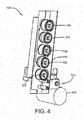
- the rubber strip path is wound around the preheat rollers as shown in Figure 4 .
- the increase in roller speed and temperature results in the strip being stretched and thinned to a strip having the desired width and thickness.
- the series of vertically oriented preheat rollers 130, 140, 150, 160, 170 process rubber stock having a 101.6 mm width, 6.35 mm thickness into a 76.2 mm wide, 3.175 mm thick strip of rubber.
- the rubber stock could be basically any size.
- the strip formed from the strip forming apparatus may be as narrow as 3.175 mm and wider and is not limited in size. Typically, the strips are in the range of 7.62 mm 50.8 m for tire building applications.
- Figure 2 illustrates the path of the rubber strip after exiting the series of vertically oriented preheat rollers 130-170.
- the rubber strip is fed into the opening 210 of a milltruder 200.
- the milltruder includes a milltruder head 220 and an application forming roller 230.
- a channel 240 is formed between the milltruder head 220 and the forming roller 230.
- Figure 2 only illustrates half of the forming roller 230 for clarity, while Figure 3 illustrates the entire forming roller 230.
- the channel 240 preferably decreases in area from the inlet to the outlet adjacent a die 250.
- the rubber is fed into the opening of the channel into engagement with the rotating forming roller and the lower end 222 of the head 220.
- the milltruder head 220 is heated.
- FIG. 3 illustrates the application forming roller 230.
- the application forming roller 230 preferably comprises a first conical half 232 and a second conical half 234 separated by a central band 236.
- the conical halves 232, 234 are preferably arranged so that the largest diameter is adjacent the band 236, while the smallest diameter is axially outward of the band 236.
- the application roller 230 may optionally comprise a plurality of grooves or serrations 238.
- the grooves or serrations 238 will increase pressure in die area which will increase output.
- the application roller 230 may optionally comprise a radial groove 260.
- the radial groove 260 is used to increase the quality of the edge of the strip. Once rubber fills the groove 260, it will flow the full 360 degrees back to the head. This action will pull any flash away from the rubber strip being applied to a tire building drum leading to a higher quality product.
- the application roller 230 As the application roller 230 rotates, it pulls rubber between the roller 230 and the milltruder head 220. As the rubber moves toward a die 250, the rubber is compressed and mixed both circumferentially and axially in the channel 240 between the milltruder head 220 and application forming roller 230. The axial mixing/movement is also increased due to the conical shape of the application roller. Since the outer diameter of the roller has a higher surface speed than the smaller diameter of the cone, rubber will tend to migrate to the surfaces with higher surface velocities, ie towards the band 236, generating additional mixing and pressure at the die opening. If more work or heat is required to process the rubber, the die 250 can be moved out to allow rubber to form a band around the application roller similar to a mill. This will allow multiple "passes" of rubber between milltruder head and roller, thus increasing work input.
- the strip forming apparatus 100 may apply a strip of rubber onto a drum 300 or onto a carcass under construction.
- the application pressure may be adjusted by adjusting the angle ⁇ that the apparatus forms with the vertical direction.
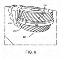
- FIG. 7 An alternate embodiment of a milltruder head 400 is shown in Figures 5-7 .
- the milltruder head 400 has a lower surface 410 having a curved surface.
- the lower surface 410 has a hole for receiving a pin 426 therein.
- the pin 426 preferably has a beveled upper surface that protrudes from the lower surface 410 of the head.
- the curved lower surface has a V shaped groove 420 with the narrow portion of the V terminating in a die outlet 430.
- the die outlet 430 is positioned adjacent the band 236.
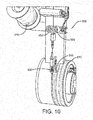
- the reinforcement applicator apparatus 500 is shown in Figures 8-10 .
- the reinforcement applicator apparatus 500 is useful to apply reinforcements such as metal wire, nylon or aramid reinforcements. Reinforcement is fed from a spool 510 through opposed rollers 520, 522 to applicator head 530. Located adjacent the applicator head 530 is stitcher roller 540 for pressing the reinforcement into the rubber surface upon which the reinforcements are applied.
- the applicator head 530 is mounted on housing. The angle of the housing with the vertical axis may be adjusted to vary the application pressure of the reinforcement onto the drum.
- the mold apparatus 700 is shown in Figure 11 .
- the mold apparatus 700 includes a plurality of segments 710 which can be arranged to form a ring about a drum 610, 620.
- the segments have an inner face 712 with desired tread pattern.
- the segments are capable of being heated to desired temperature in order to cure the rubber component.
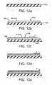
- a method of forming a shearband onto a drum 610 is illustrated in Figures 12a through 12e .
- a first step to form a shearband is to use the strip forming apparatus 100 to apply a continuous strip 800 of rubber onto the drum 610 to form a first rubber layer 810.
- the layer is formed by spirally winding the continuous strip 800 about the drum 610.
- the direction of traverse in this example is from left to right.
- the reinforcement applicator 500 is used to apply a first reinforcement layer 820 over the first rubber layer 810 by traversing the reinforcement applicator 500 from right to left as the drum rotates, so that the reinforcement is applied over the first rubber layer 810.
- the reinforcement is spirally wound over the first rubber layer 810.
- the reinforcement is pressed into the first rubber layer 810 by the stitcher roller 540.
- the strip forming apparatus 100 is able to be in close proximity to the reinforcement applicator in a side by side manner.
- the strip forming apparatus 100 may continuously wind a strip of rubber over the first reinforcement layer 820 while the reinforcement applicator is applying the first reinforcement layer.
- a shearband having the desired number of rubber and reinforcement layers.
- the shearband may include 3 layers of spirally wound reinforcements separated from each other by two layers of rubber, for a total of 6 layers of rubber. An additional 3 layers of rubber is added for the tread layer.
- the reinforcement applicator 500 and the strip applicator 100 may be used in conjunction with conventional tire building drums.
- the reinforcement applicator 500 may be used to form belts directly onto a shaped toroidal carcass that is mounted on a tire building drum.
- the reinforcement applicator may form one or more zigzag belts.
- the strip applicator may be used to spirally wind a strip of rubber directly onto the carcass to form a tread.
- a spliceless tread is built onto the drum 610, and is useful in retreading operations.
- the strip forming apparatus 100 is used to apply a continuous strip 800 of rubber onto the carcass to form one or more rubber layers. Typically, at least three layers of rubber is needed to form a tread ring.
- the tread ring is then inserted into mold 700 and then cured.
- the cured tread ring may then be mounted and then glued onto a buffed carcass as known to those skilled in the art of retreading of tires.
- the advantages of the system are: Significant reductions in capital costs of a system vs extrusion. Significantly lower horsepower required (lower energy costs). Since the size of the system is small, multiple strips can be applied to the building drum simultaneously. This reduces capital cost and increases output because fewer drums and less conveying of building drums is required. Since the entire assembly is hanging vertically, stitching application pressures can be more easily achieved vs present extrusion technology. This leads to reduced trapped air and a higher quality product. Being able to control this stitching pressure also allows for reinforcement to be applied directly to the building drum without pre-calendering, further reducing complexity and costs.
Description
- The invention relates generally to rubber processing, and more particularly to a method and apparatus for forming a rubber component such as a tread, shear band or other rubber component with reinforcements.
- The invention describes a method and apparatus capable of making a rubber component that is reinforced with metal or nonmetal reinforcements. The rubber component may be for example a belt and tread ring assembly or a shear band and tread assembly for a non-pneumatic tire. Typical prior art methods generally utilize expensive equipment such as gear pumps and extruders in order to form a strip of rubber for strip lamination of components. Extruders are typically very high pressure and require large amounts of horsepower in order to form a small strip. Extruders are expensive, and if not used properly, may overheat or overwork the rubber. Thus, an apparatus and method of efficiently producing reinforced rubber component is desired.
-
US-A- 2005/0051256 describes an apparatus in accordance with the preamble of claim 1. - The invention relates to an apparatus in accordance with claim 1, and to a method in accordance with claim 7.
- Dependent claims refer to preferred embodiments of the invention.
- One or more embodiments of the present invention provide an apparatus for forming a reinforced rubber component, the apparatus comprising a support frame, a rotatable drum mounted upon the support frame, a rubber strip forming apparatus mounted in close proximity to the rotatable drum for applying a rubber strip onto the rotatable drum, and a reinforcement applier apparatus for applying a reinforcement onto the rotatable drum.
- Preferably, an upper end of the rubber strip forming apparatus is mounted on a rail and capable of translating in a direction parallel to a rotational axis of the rotatable drum and/or an upper end of the reinforcement applier apparatus is mounted on a rail and capable of translating in a direction parallel to a rotational axis of the rotatable drum.
- Preferably, the reinforcement applier apparatus and the rubber strip forming apparatus are located adjacent each other.
- The angle of the reinforcement applier apparatus with the vertical axis is adjustable and/or the angle of the strip forming apparatus with the vertical axis is adjustable.
- In a preferred aspect of the invention, the strip forming apparatus comprises a support frame, a first and second roller mounted on the support frame, wherein the first and second rollers are spaced apart from each other, and an application roller located adjacent a milltruder head, and a channel formed in the space between the head and the outer surface of the application roller and the inner surface of the milltruder head; wherein said channel has an inlet and an outlet, wherein the inlet is located near the second roller, and the outlet is located adjacent a die.
- In a preferred aspect of the invention, the support frame is rotatable.
- In a preferred aspect of the invention, the support frame is translatable in a direction parallel to the rotational axis of the rotatable drum.
- One or more embodiments of the present invention provide a method of forming a reinforced rubber component, the method comprising the steps of providing a rotatable drum, applying a rubber strip onto the rotatable drum to form a first rubber layer in a first direction, applying a reinforcement over the first rubber layer in a second direction opposite the first direction to form a first reinforcement layer, and applying a rubber strip over the first reinforcement layer.
- The rubber strip and the reinforcement is spirally wound on the rotating drum.
- In a preferred aspect of the invention, the reinforcement and the rubber strip is applied on the rotatable drum at the same time.
- In a preferred aspect of the invention, the reinforcement applier and the rubber strip applier are located adjacent each other.
- In a preferred aspect of the invention, the reinforced rubber component is a shear band or a belt and tread assembly.
- One or more embodiments of the present invention provides a method of forming a spliceless tread ring, the method comprising the steps of providing a rotatable drum, applying a rubber strip onto the rotatable drum to form at least three rubber layers, wherein the strip is spirally wound on the rotatable drum to form a green tread ring, and inserting the green tread ring in a mold and curing the tread ring.
- One or more embodiments of the present invention provides a method of forming a tire, the method comprising the steps of providing a tire carcass and mounting it on a rotatable drum, applying a rubber strip onto the tire carcass to form at least three rubber layers, wherein the strip is spirally wound to form a green tread ring, and curing the green tread ring and the tire carcass in a mold.
- The invention will be described by way of example and with reference to the accompanying drawings in which:
-
Figure 1 is a front perspective view of a strip forming apparatus of the present invention; -
Figure 2 is a closeup view of the strip forming apparatus ofFigure 1 shown with only half of the application roller for clarity; -
Figure 3 is a front view of the applicator wheel ofFigure 2 ; -
Figure 4 is a front perspective view of the strip forming apparatus illustrating the path of the rubber; -
Figures 5 and6 are a side views of a second embodiment of a milltruder head and the application roller from different angles; -
Figure 7 is a bottom view of the milltruder head ofFigure 5 ; -
Figure 8 is a front view of a reinforced rubber component making apparatus of the present invention; -
Figure 9 is a front view of a wire applicator apparatus of the present invention; -
Figure 10 is a front close up view of the wire applicator apparatus ofFigure 9 ; -
Figure 11 is a front view of a mold; -
Figures 12a through 12e are schematics illustrating the steps for forming a reinforced rubber component. - The invention as described herein provides a method and apparatus for forming reinforced rubber components. The reinforced rubber components may include for example, a belt and tread structure useful for a pneumatic tire, or, in another example, a shear band useful for a non-pneumatic tire.
- The invention includes a
strip forming apparatus 100 as shown inFigures 1-7 and described in more detail, below. The invention further includes awire applicator apparatus 500 as reinforcement applier apparatus as shown inFigures 8-10 and described in more detail, below. - The
strip forming apparatus 100 andwire applicator 500 may be used in conjunction with drum system 600, shown inFigure 8 . The drum system 600 preferably includes a first andsecond drum second drum support frame 630 which is preferably rotatably mounted oncolumn 640. Thesupport frame 630 preferably can rotate at least 180 degrees oncolumn 640. Thecolumn 640 is preferably mounted tolower support frame 650 which can slide onrails 660. The first andsecond drums rails 660 to amold ring apparatus 700. Preferably, there are twomold ring apparati 700. - Referring to
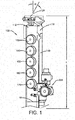
FIG. 1 , astrip forming apparatus 100 is shown. Thestrip forming apparatus 100 includes amounting frame 110 that is preferably rectangular in shape, with a significantly longer vertical length than width. Themounting frame 110 has anupper end 112 that is preferably pivotally mounted to aservomechanism 120. Theservomechanism 120 functions to traverse the mounting frame forward and aft. Themounting frame 110 preferably hangs vertically on the servomechanism allowing the stitching pressure to be adjusted by the traverse position. The angle α that the strip forming apparatus makes with the vertical direction may preferably be adjusted by aservo mechanism 118. In order to adjust the stitching pressure, the angle α of the strip forming apparatus is varied. Variation of the angle changes the stitching pressure. Very low stitching pressure can be achieved which is required for small rubber strips. The stitching pressure can be adjusted by the traverse position of the strip forming apparatus in relation to a tire building drum, as described in more detail below. - As shown in
Figure 1 , themounting frame 110 has a length L and a width W, wherein the length L is preferably aligned with the vertical direction. The length/width ratio is preferably greater than 10. The mountingframe 110 has a plurality (at least two) of spaced apart preheatrollers - Each preheat roller preferably has internal heaters (not shown). Preferably, each preheat roller is heated to a different temperature than the other preheat rollers. Preferably, the preheat rollers are progressively heated to a higher temperature so that the
first preheat roller 130 is the coolest roller, while thesecond preheat roller 140 is heated to a higher temperature than thefirst preheat roller 130. Thethird preheat roller 150 is heated to a higher temperature than thesecond preheat roller 140, and thefourth preheat roller 160 is heated to a higher temperature than thethird preheat roller 150. Likewise, thefifth preheat roller 170 is heated to a higher temperature than thefourth preheat roller 160. In summary, the preheat rollers are preferably maintained at progressively higher temperatures, increasing in temperature in the incremental range of from 5-20 degrees per roller with decreasing height of the mounting frame, so that the first orhighest roller 130 is the coolest and the lowest roller is the hottest. - It is also preferred that the preheat rollers progressively increase in rotational speed from the highest
vertical roller 130 to the lowestvertical roller 170, so that the lowestvertical roller 170 is the fastest. - The rubber strip path is wound around the preheat rollers as shown in
Figure 4 . As the rubber strip is wound around the preheat rollers, the increase in roller speed and temperature results in the strip being stretched and thinned to a strip having the desired width and thickness. In a first example, the series of vertically orientedpreheat rollers -
Figure 2 illustrates the path of the rubber strip after exiting the series of vertically oriented preheat rollers 130-170. The rubber strip is fed into theopening 210 of amilltruder 200. The milltruder includes a milltruder head 220 and anapplication forming roller 230. Achannel 240 is formed between the milltruder head 220 and the formingroller 230.Figure 2 only illustrates half of the formingroller 230 for clarity, whileFigure 3 illustrates the entire formingroller 230. Thechannel 240 preferably decreases in area from the inlet to the outlet adjacent adie 250. The rubber is fed into the opening of the channel into engagement with the rotating forming roller and thelower end 222 of the head 220. Preferably, the milltruder head 220 is heated. -
Figure 3 illustrates theapplication forming roller 230. Theapplication forming roller 230 preferably comprises a firstconical half 232 and a secondconical half 234 separated by acentral band 236. Theconical halves band 236, while the smallest diameter is axially outward of theband 236. Theapplication roller 230 may optionally comprise a plurality of grooves orserrations 238. The grooves orserrations 238 will increase pressure in die area which will increase output. Theapplication roller 230 may optionally comprise aradial groove 260. Theradial groove 260 is used to increase the quality of the edge of the strip. Once rubber fills thegroove 260, it will flow the full 360 degrees back to the head. This action will pull any flash away from the rubber strip being applied to a tire building drum leading to a higher quality product. - As the
application roller 230 rotates, it pulls rubber between theroller 230 and the milltruder head 220. As the rubber moves toward adie 250, the rubber is compressed and mixed both circumferentially and axially in thechannel 240 between the milltruder head 220 andapplication forming roller 230. The axial mixing/movement is also increased due to the conical shape of the application roller. Since the outer diameter of the roller has a higher surface speed than the smaller diameter of the cone, rubber will tend to migrate to the surfaces with higher surface velocities, ie towards theband 236, generating additional mixing and pressure at the die opening. If more work or heat is required to process the rubber, thedie 250 can be moved out to allow rubber to form a band around the application roller similar to a mill. This will allow multiple "passes" of rubber between milltruder head and roller, thus increasing work input. - The
strip forming apparatus 100 may apply a strip of rubber onto adrum 300 or onto a carcass under construction. The application pressure may be adjusted by adjusting the angle α that the apparatus forms with the vertical direction. - An alternate embodiment of a milltruder
head 400 is shown inFigures 5-7 . As shown inFigure 7 , the milltruderhead 400 has alower surface 410 having a curved surface. Thelower surface 410 has a hole for receiving a pin 426 therein. The pin 426 preferably has a beveled upper surface that protrudes from thelower surface 410 of the head. The curved lower surface has a V shapedgroove 420 with the narrow portion of the V terminating in adie outlet 430. Thedie outlet 430 is positioned adjacent theband 236. - The
reinforcement applicator apparatus 500 is shown inFigures 8-10 . Thereinforcement applicator apparatus 500 is useful to apply reinforcements such as metal wire, nylon or aramid reinforcements. Reinforcement is fed from aspool 510 through opposedrollers applicator head 530. Located adjacent theapplicator head 530 isstitcher roller 540 for pressing the reinforcement into the rubber surface upon which the reinforcements are applied. Theapplicator head 530 is mounted on housing. The angle of the housing with the vertical axis may be adjusted to vary the application pressure of the reinforcement onto the drum. - The
mold apparatus 700 is shown inFigure 11 . Themold apparatus 700 includes a plurality ofsegments 710 which can be arranged to form a ring about adrum inner face 712 with desired tread pattern. The segments are capable of being heated to desired temperature in order to cure the rubber component. - A method of forming a shearband onto a
drum 610 is illustrated inFigures 12a through 12e . As shown inFigure 12b , a first step to form a shearband is to use thestrip forming apparatus 100 to apply acontinuous strip 800 of rubber onto thedrum 610 to form afirst rubber layer 810. Preferably, the layer is formed by spirally winding thecontinuous strip 800 about thedrum 610. The direction of traverse in this example is from left to right. Next in a second step, thereinforcement applicator 500 is used to apply afirst reinforcement layer 820 over thefirst rubber layer 810 by traversing thereinforcement applicator 500 from right to left as the drum rotates, so that the reinforcement is applied over thefirst rubber layer 810. Preferably, the reinforcement is spirally wound over thefirst rubber layer 810. The reinforcement is pressed into thefirst rubber layer 810 by thestitcher roller 540. Thestrip forming apparatus 100 is able to be in close proximity to the reinforcement applicator in a side by side manner. Thus, in a third step, thestrip forming apparatus 100 may continuously wind a strip of rubber over thefirst reinforcement layer 820 while the reinforcement applicator is applying the first reinforcement layer. - These steps one through three may be repeated in order to build a shear band having the desired number of rubber and reinforcement layers. In a second embodiment of a shearband, there are at least two layers of rubber between the reinforcement layer. The shearband may include 3 layers of spirally wound reinforcements separated from each other by two layers of rubber, for a total of 6 layers of rubber. An additional 3 layers of rubber is added for the tread layer. After the shearband is formed on the drum, the drum may be slid on rails and inserted into mold. The mold segments are moved radially inwards about the shearband, and the mold segments are heated to the desired temperature to cure the shearband.
- The
reinforcement applicator 500 and thestrip applicator 100 may be used in conjunction with conventional tire building drums. In one embodiment, thereinforcement applicator 500 may be used to form belts directly onto a shaped toroidal carcass that is mounted on a tire building drum. The reinforcement applicator may form one or more zigzag belts. The strip applicator may be used to spirally wind a strip of rubber directly onto the carcass to form a tread. - In this embodiment, a spliceless tread is built onto the
drum 610, and is useful in retreading operations. Thestrip forming apparatus 100 is used to apply acontinuous strip 800 of rubber onto the carcass to form one or more rubber layers. Typically, at least three layers of rubber is needed to form a tread ring. The tread ring is then inserted intomold 700 and then cured. The cured tread ring may then be mounted and then glued onto a buffed carcass as known to those skilled in the art of retreading of tires. - The advantages of the system are: Significant reductions in capital costs of a system vs extrusion. Significantly lower horsepower required (lower energy costs). Since the size of the system is small, multiple strips can be applied to the building drum simultaneously. This reduces capital cost and increases output because fewer drums and less conveying of building drums is required. Since the entire assembly is hanging vertically, stitching application pressures can be more easily achieved vs present extrusion technology. This leads to reduced trapped air and a higher quality product. Being able to control this stitching pressure also allows for reinforcement to be applied directly to the building drum without pre-calendering, further reducing complexity and costs.
Claims (11)
- An apparatus for forming a reinforced rubber component, the apparatus comprising:a support frame (630);a rotatable drum (610) mounted upon the support frame (630);a rubber strip forming apparatus (100) mounted in proximity to the rotatable drum (610) for applying a rubber strip onto the rotatable drum (610); anda reinforcement applier apparatus (500) for applying a reinforcement onto the rotatable drum (610), characterized in that the angle of the reinforcement applier apparatus (500) with the vertical axis is adjustable and/or wherein the angle of the strip forming apparatus (100) with the vertical axis is adjustable.
- The apparatus of claim 1 wherein an upper end of the rubber strip forming apparatus (100) is mounted on a rail and capable of translating in a direction parallel to a rotational axis of the rotatable drum (610).
- The apparatus of claim 1 or 2 wherein an upper end of the reinforcement applier apparatus (500) is mounted on a rail and capable of translating in a direction parallel to a rotational axis of the rotatable drum (610).
- The apparatus of at least one of the previous claims wherein the reinforcement applier apparatus (500) and the rubber strip forming apparatus (100) are located adjacent each other.
- The apparatus of at least one of the previous claims wherein the rubber strip forming apparatus (100) comprises:a support frame (110);at least a first and a second roller (160, 170) mounted on the support frame (110), wherein the first and second rollers are spaced apart from each other; andan application roller (230) located adjacent a milltruder head (220, 400) and a channel (240) formed in a space between the milltruder head (220, 400) and an outer surface of the application roller (230), wherein the channel (240) has an inlet and an outlet, wherein the inlet is located in proximity to the second roller (170), and wherein the outlet is located adjacent a die (250).
- The apparatus of at least one of the previous claims wherein the support frame (630) is rotatable and/or wherein the support frame (630) is translatable in a direction parallel to the rotational axis of the rotatable drum (610).
- A method of forming a reinforced rubber component, the method comprising the steps of:providing an apparatus according to any of the preceding claims;applying a rubber strip onto the rotatable drum (610) to form a first rubber layer (810) in a first direction;applying a reinforcement over the first rubber layer (820) in a second direction opposite to the first direction to form a first reinforcement layer (820); andapplying a rubber strip over the first reinforcement layer (820), wherein the rubber strip and the reinforcement is spirally wound on the rotating drum (610).
- The method of claim 7 wherein the reinforcement and the rubber strip is applied on the rotatable drum (610) at the same time.
- The method of at least one of the claims 7 or 8 wherein the reinforcement is applied to the rotating drum (610) by a reinforcement applier (500) and the rubber strip is applied to the rotating drum (610) by a rubber strip applier (100), and wherein the reinforcement applier (500) and the rubber strip applier (100) are located adjacent each other.
- The method of at least one of the claims 7 to 9 wherein the reinforced rubber component is a shear band.
- The method of at least one of the claims 7 to 9 wherein the reinforced rubber component is a belt and tread assembly.
Applications Claiming Priority (1)
| Application Number | Priority Date | Filing Date | Title |
|---|---|---|---|
| US15/846,822 US20190184657A1 (en) | 2017-12-19 | 2017-12-19 | Method and apparatus for forming rubber reinforced component |
Publications (2)
| Publication Number | Publication Date |
|---|---|
| EP3501807A1 EP3501807A1 (en) | 2019-06-26 |
| EP3501807B1 true EP3501807B1 (en) | 2020-11-25 |
Family
ID=64665700
Family Applications (1)
| Application Number | Title | Priority Date | Filing Date |
|---|---|---|---|
| EP18212741.5A Active EP3501807B1 (en) | 2017-12-19 | 2018-12-14 | Method and apparatus for forming rubber reinforced component |
Country Status (3)
| Country | Link |
|---|---|
| US (1) | US20190184657A1 (en) |
| EP (1) | EP3501807B1 (en) |
| CN (1) | CN110001099A (en) |
Families Citing this family (1)
| Publication number | Priority date | Publication date | Assignee | Title |
|---|---|---|---|---|
| CN110177681B (en) * | 2016-12-16 | 2022-01-18 | 倍耐力轮胎股份公司 | Method for inspecting a continuous elongated element during the building of a tyre for vehicle wheels and apparatus for building a tyre for vehicle wheels |
Family Cites Families (13)
| Publication number | Priority date | Publication date | Assignee | Title |
|---|---|---|---|---|
| US2382177A (en) * | 1941-10-15 | 1945-08-14 | Goodrich Co B F | Apparatus for making composite strips |
| US5030079A (en) * | 1989-10-27 | 1991-07-09 | The Goodyear Tire & Rubber Company | Roller die extrusion and calendering apparatus |
| JP3124561B2 (en) * | 1991-02-01 | 2001-01-15 | 株式会社ブリヂストン | Rubber sheet member for tire |
| EP1230080B2 (en) * | 1999-11-19 | 2010-04-28 | PIRELLI TYRE S.p.A. | A method for manufacturing elastomeric material components of a tyre for vehicle wheels |
| US20040231779A1 (en) * | 2003-05-20 | 2004-11-25 | Jean-Claude Girard | Method and apparatus for tread belt assembly |
| US20050051256A1 (en) * | 2003-09-09 | 2005-03-10 | Yovichin Albert James | Method and apparatus for building and transferring a tread belt structure |
| EP2065171B1 (en) * | 2006-09-12 | 2011-11-16 | Toyo Tire & Rubber Co. Ltd. | Process for producing tire |
| US20100212812A1 (en) * | 2007-09-05 | 2010-08-26 | Bridgestone Corporation | Method and device for producing green tire |
| JP5356534B2 (en) * | 2008-12-05 | 2013-12-04 | ミシュラン ルシェルシュ エ テクニーク ソシエテ アノニム | Method and apparatus for forming tire components on an axially tapered molding surface |
| WO2011021702A1 (en) * | 2009-08-20 | 2011-02-24 | 株式会社ブリヂストン | Tire and tire manufacturing method |
| JP6117082B2 (en) * | 2013-11-21 | 2017-04-19 | 東洋ゴム工業株式会社 | Method and device for applying strip rubber |
| CN103707537B (en) * | 2013-12-30 | 2015-09-23 | 萨驰华辰机械(苏州)有限公司 | High efficiency car radial tire former |
| WO2017116822A1 (en) * | 2015-12-30 | 2017-07-06 | Bridgestone Americas Tire Operations, Llc | Tire with pre-formed ribbon tread and method of making same |
-
2017
- 2017-12-19 US US15/846,822 patent/US20190184657A1/en not_active Abandoned
-
2018
- 2018-12-14 EP EP18212741.5A patent/EP3501807B1/en active Active
- 2018-12-19 CN CN201811558732.7A patent/CN110001099A/en active Pending
Non-Patent Citations (1)
| Title |
|---|
| None * |
Also Published As
| Publication number | Publication date |
|---|---|
| CN110001099A (en) | 2019-07-12 |
| EP3501807A1 (en) | 2019-06-26 |
| US20190184657A1 (en) | 2019-06-20 |
Similar Documents
| Publication | Publication Date | Title |
|---|---|---|
| US11931980B2 (en) | Process and apparatus for building tyres | |
| US20070289694A1 (en) | Method for laying carcass reinforcement plies | |
| JP4902549B2 (en) | Method and apparatus for manufacturing and arranging tire circumferential reinforcement and tire obtained by this method | |
| EP3225386B1 (en) | System for adjusting a path of a wire | |
| US11623187B2 (en) | Extrusion device and process for extruding a semi-finished product made of elastomeric material | |
| EP3260285A1 (en) | An apparatus for forming an elastomeric strip with rotatable nozzle applicator | |
| US20060048878A1 (en) | Tire manufacturing method cover rubber stamping device used for the manufacturing method, tire rubber sheet member stamping method , and rubber sheet member stamping device | |
| CN106715104B (en) | Stretching device for tri filling adhesive tape and the apex strip handling system including the stretching device | |
| EP3501807B1 (en) | Method and apparatus for forming rubber reinforced component | |
| US5108682A (en) | Coextrusion apparatus and method using an elastic die for varying the outer profile of a tubular extrudate | |
| US5069850A (en) | Coextrusion apparatus and method using a rigid die for varying the outer profile of a tubular extrudate | |
| MX2015003999A (en) | Method for controlling the thickness of a continuous elongated element made of elastomeric material in a process for building tyres. | |
| US5174845A (en) | Insulation wrapping strip with variable configuration | |
| EP3670141B1 (en) | Methods of making composite innerliner and tire having such a composite innerliner | |
| EP1749649A2 (en) | A method for forming an elastomeric component | |
| EP3501780B1 (en) | Rubber strip manufacturing method and apparatus | |
| EP3112142B1 (en) | Apparatus and method for forming an elastomeric strip | |
| US4569711A (en) | Manufacture of elastomeric material coponents | |
| US5098277A (en) | Insulation wrapping strip with variable configuration | |
| JP2014133418A (en) | Method and apparatus for tire formation | |
| WO1999061230A1 (en) | A method and apparatus for forming tire components | |
| JP2008018620A (en) | Method for manufacturing pneumatic tire, and pneumatic tire | |
| CN1426885A (en) | Method and device for forming tyre parts |
Legal Events
| Date | Code | Title | Description |
|---|---|---|---|
| PUAI | Public reference made under article 153(3) epc to a published international application that has entered the european phase |
Free format text: ORIGINAL CODE: 0009012 |
|
| STAA | Information on the status of an ep patent application or granted ep patent |
Free format text: STATUS: THE APPLICATION HAS BEEN PUBLISHED |
|
| AK | Designated contracting states |
Kind code of ref document: A1 Designated state(s): AL AT BE BG CH CY CZ DE DK EE ES FI FR GB GR HR HU IE IS IT LI LT LU LV MC MK MT NL NO PL PT RO RS SE SI SK SM TR |
|
| AX | Request for extension of the european patent |
Extension state: BA ME |
|
| STAA | Information on the status of an ep patent application or granted ep patent |
Free format text: STATUS: REQUEST FOR EXAMINATION WAS MADE |
|
| 17P | Request for examination filed |
Effective date: 20200102 |
|
| RBV | Designated contracting states (corrected) |
Designated state(s): AL AT BE BG CH CY CZ DE DK EE ES FI FR GB GR HR HU IE IS IT LI LT LU LV MC MK MT NL NO PL PT RO RS SE SI SK SM TR |
|
| GRAP | Despatch of communication of intention to grant a patent |
Free format text: ORIGINAL CODE: EPIDOSNIGR1 |
|
| STAA | Information on the status of an ep patent application or granted ep patent |
Free format text: STATUS: GRANT OF PATENT IS INTENDED |
|
| RIC1 | Information provided on ipc code assigned before grant |
Ipc: B29D 30/00 20060101ALI20200520BHEP Ipc: B29D 30/60 20060101ALI20200520BHEP Ipc: B29D 30/62 20060101ALI20200520BHEP Ipc: B29D 30/02 20060101ALI20200520BHEP Ipc: B29D 30/30 20060101AFI20200520BHEP |
|
| INTG | Intention to grant announced |
Effective date: 20200612 |
|
| GRAS | Grant fee paid |
Free format text: ORIGINAL CODE: EPIDOSNIGR3 |
|
| GRAA | (expected) grant |
Free format text: ORIGINAL CODE: 0009210 |
|
| STAA | Information on the status of an ep patent application or granted ep patent |
Free format text: STATUS: THE PATENT HAS BEEN GRANTED |
|
| AK | Designated contracting states |
Kind code of ref document: B1 Designated state(s): AL AT BE BG CH CY CZ DE DK EE ES FI FR GB GR HR HU IE IS IT LI LT LU LV MC MK MT NL NO PL PT RO RS SE SI SK SM TR |
|
| REG | Reference to a national code |
Ref country code: GB Ref legal event code: FG4D |
|
| REG | Reference to a national code |
Ref country code: CH Ref legal event code: EP |
|
| REG | Reference to a national code |
Ref country code: DE Ref legal event code: R096 Ref document number: 602018010106 Country of ref document: DE |
|
| REG | Reference to a national code |
Ref country code: AT Ref legal event code: REF Ref document number: 1337811 Country of ref document: AT Kind code of ref document: T Effective date: 20201215 |
|
| REG | Reference to a national code |
Ref country code: IE Ref legal event code: FG4D |
|
| REG | Reference to a national code |
Ref country code: NL Ref legal event code: FP |
|
| REG | Reference to a national code |
Ref country code: AT Ref legal event code: MK05 Ref document number: 1337811 Country of ref document: AT Kind code of ref document: T Effective date: 20201125 |
|
| PG25 | Lapsed in a contracting state [announced via postgrant information from national office to epo] |
Ref country code: FI Free format text: LAPSE BECAUSE OF FAILURE TO SUBMIT A TRANSLATION OF THE DESCRIPTION OR TO PAY THE FEE WITHIN THE PRESCRIBED TIME-LIMIT Effective date: 20201125 Ref country code: RS Free format text: LAPSE BECAUSE OF FAILURE TO SUBMIT A TRANSLATION OF THE DESCRIPTION OR TO PAY THE FEE WITHIN THE PRESCRIBED TIME-LIMIT Effective date: 20201125 Ref country code: PT Free format text: LAPSE BECAUSE OF FAILURE TO SUBMIT A TRANSLATION OF THE DESCRIPTION OR TO PAY THE FEE WITHIN THE PRESCRIBED TIME-LIMIT Effective date: 20210325 Ref country code: GR Free format text: LAPSE BECAUSE OF FAILURE TO SUBMIT A TRANSLATION OF THE DESCRIPTION OR TO PAY THE FEE WITHIN THE PRESCRIBED TIME-LIMIT Effective date: 20210226 Ref country code: NO Free format text: LAPSE BECAUSE OF FAILURE TO SUBMIT A TRANSLATION OF THE DESCRIPTION OR TO PAY THE FEE WITHIN THE PRESCRIBED TIME-LIMIT Effective date: 20210225 |
|
| PG25 | Lapsed in a contracting state [announced via postgrant information from national office to epo] |
Ref country code: BG Free format text: LAPSE BECAUSE OF FAILURE TO SUBMIT A TRANSLATION OF THE DESCRIPTION OR TO PAY THE FEE WITHIN THE PRESCRIBED TIME-LIMIT Effective date: 20210225 Ref country code: SE Free format text: LAPSE BECAUSE OF FAILURE TO SUBMIT A TRANSLATION OF THE DESCRIPTION OR TO PAY THE FEE WITHIN THE PRESCRIBED TIME-LIMIT Effective date: 20201125 Ref country code: IS Free format text: LAPSE BECAUSE OF FAILURE TO SUBMIT A TRANSLATION OF THE DESCRIPTION OR TO PAY THE FEE WITHIN THE PRESCRIBED TIME-LIMIT Effective date: 20210325 Ref country code: PL Free format text: LAPSE BECAUSE OF FAILURE TO SUBMIT A TRANSLATION OF THE DESCRIPTION OR TO PAY THE FEE WITHIN THE PRESCRIBED TIME-LIMIT Effective date: 20201125 Ref country code: LV Free format text: LAPSE BECAUSE OF FAILURE TO SUBMIT A TRANSLATION OF THE DESCRIPTION OR TO PAY THE FEE WITHIN THE PRESCRIBED TIME-LIMIT Effective date: 20201125 Ref country code: AT Free format text: LAPSE BECAUSE OF FAILURE TO SUBMIT A TRANSLATION OF THE DESCRIPTION OR TO PAY THE FEE WITHIN THE PRESCRIBED TIME-LIMIT Effective date: 20201125 |
|
| REG | Reference to a national code |
Ref country code: LT Ref legal event code: MG9D |
|
| PG25 | Lapsed in a contracting state [announced via postgrant information from national office to epo] |
Ref country code: HR Free format text: LAPSE BECAUSE OF FAILURE TO SUBMIT A TRANSLATION OF THE DESCRIPTION OR TO PAY THE FEE WITHIN THE PRESCRIBED TIME-LIMIT Effective date: 20201125 |
|
| PG25 | Lapsed in a contracting state [announced via postgrant information from national office to epo] |
Ref country code: SK Free format text: LAPSE BECAUSE OF FAILURE TO SUBMIT A TRANSLATION OF THE DESCRIPTION OR TO PAY THE FEE WITHIN THE PRESCRIBED TIME-LIMIT Effective date: 20201125 Ref country code: SM Free format text: LAPSE BECAUSE OF FAILURE TO SUBMIT A TRANSLATION OF THE DESCRIPTION OR TO PAY THE FEE WITHIN THE PRESCRIBED TIME-LIMIT Effective date: 20201125 Ref country code: CZ Free format text: LAPSE BECAUSE OF FAILURE TO SUBMIT A TRANSLATION OF THE DESCRIPTION OR TO PAY THE FEE WITHIN THE PRESCRIBED TIME-LIMIT Effective date: 20201125 Ref country code: EE Free format text: LAPSE BECAUSE OF FAILURE TO SUBMIT A TRANSLATION OF THE DESCRIPTION OR TO PAY THE FEE WITHIN THE PRESCRIBED TIME-LIMIT Effective date: 20201125 Ref country code: RO Free format text: LAPSE BECAUSE OF FAILURE TO SUBMIT A TRANSLATION OF THE DESCRIPTION OR TO PAY THE FEE WITHIN THE PRESCRIBED TIME-LIMIT Effective date: 20201125 Ref country code: LT Free format text: LAPSE BECAUSE OF FAILURE TO SUBMIT A TRANSLATION OF THE DESCRIPTION OR TO PAY THE FEE WITHIN THE PRESCRIBED TIME-LIMIT Effective date: 20201125 |
|
| REG | Reference to a national code |
Ref country code: DE Ref legal event code: R097 Ref document number: 602018010106 Country of ref document: DE |
|
| PG25 | Lapsed in a contracting state [announced via postgrant information from national office to epo] |
Ref country code: MC Free format text: LAPSE BECAUSE OF FAILURE TO SUBMIT A TRANSLATION OF THE DESCRIPTION OR TO PAY THE FEE WITHIN THE PRESCRIBED TIME-LIMIT Effective date: 20201125 Ref country code: DK Free format text: LAPSE BECAUSE OF FAILURE TO SUBMIT A TRANSLATION OF THE DESCRIPTION OR TO PAY THE FEE WITHIN THE PRESCRIBED TIME-LIMIT Effective date: 20201125 |
|
| REG | Reference to a national code |
Ref country code: BE Ref legal event code: MM Effective date: 20201231 |
|
| PLBE | No opposition filed within time limit |
Free format text: ORIGINAL CODE: 0009261 |
|
| STAA | Information on the status of an ep patent application or granted ep patent |
Free format text: STATUS: NO OPPOSITION FILED WITHIN TIME LIMIT |
|
| PG25 | Lapsed in a contracting state [announced via postgrant information from national office to epo] |
Ref country code: AL Free format text: LAPSE BECAUSE OF FAILURE TO SUBMIT A TRANSLATION OF THE DESCRIPTION OR TO PAY THE FEE WITHIN THE PRESCRIBED TIME-LIMIT Effective date: 20201125 Ref country code: IE Free format text: LAPSE BECAUSE OF NON-PAYMENT OF DUE FEES Effective date: 20201214 Ref country code: LU Free format text: LAPSE BECAUSE OF NON-PAYMENT OF DUE FEES Effective date: 20201214 |
|
| 26N | No opposition filed |
Effective date: 20210826 |
|
| PG25 | Lapsed in a contracting state [announced via postgrant information from national office to epo] |
Ref country code: SI Free format text: LAPSE BECAUSE OF FAILURE TO SUBMIT A TRANSLATION OF THE DESCRIPTION OR TO PAY THE FEE WITHIN THE PRESCRIBED TIME-LIMIT Effective date: 20201125 |
|
| PG25 | Lapsed in a contracting state [announced via postgrant information from national office to epo] |
Ref country code: ES Free format text: LAPSE BECAUSE OF FAILURE TO SUBMIT A TRANSLATION OF THE DESCRIPTION OR TO PAY THE FEE WITHIN THE PRESCRIBED TIME-LIMIT Effective date: 20201125 |
|
| PG25 | Lapsed in a contracting state [announced via postgrant information from national office to epo] |
Ref country code: IS Free format text: LAPSE BECAUSE OF FAILURE TO SUBMIT A TRANSLATION OF THE DESCRIPTION OR TO PAY THE FEE WITHIN THE PRESCRIBED TIME-LIMIT Effective date: 20210325 Ref country code: MT Free format text: LAPSE BECAUSE OF FAILURE TO SUBMIT A TRANSLATION OF THE DESCRIPTION OR TO PAY THE FEE WITHIN THE PRESCRIBED TIME-LIMIT Effective date: 20201125 Ref country code: CY Free format text: LAPSE BECAUSE OF FAILURE TO SUBMIT A TRANSLATION OF THE DESCRIPTION OR TO PAY THE FEE WITHIN THE PRESCRIBED TIME-LIMIT Effective date: 20201125 |
|
| PG25 | Lapsed in a contracting state [announced via postgrant information from national office to epo] |
Ref country code: MK Free format text: LAPSE BECAUSE OF FAILURE TO SUBMIT A TRANSLATION OF THE DESCRIPTION OR TO PAY THE FEE WITHIN THE PRESCRIBED TIME-LIMIT Effective date: 20201125 |
|
| PG25 | Lapsed in a contracting state [announced via postgrant information from national office to epo] |
Ref country code: BE Free format text: LAPSE BECAUSE OF NON-PAYMENT OF DUE FEES Effective date: 20201231 |
|
| REG | Reference to a national code |
Ref country code: CH Ref legal event code: PL |
|
| PG25 | Lapsed in a contracting state [announced via postgrant information from national office to epo] |
Ref country code: LI Free format text: LAPSE BECAUSE OF NON-PAYMENT OF DUE FEES Effective date: 20211231 Ref country code: CH Free format text: LAPSE BECAUSE OF NON-PAYMENT OF DUE FEES Effective date: 20211231 |
|
| PGFP | Annual fee paid to national office [announced via postgrant information from national office to epo] |
Ref country code: NL Payment date: 20221019 Year of fee payment: 5 Ref country code: FR Payment date: 20221010 Year of fee payment: 5 |
|
| PGFP | Annual fee paid to national office [announced via postgrant information from national office to epo] |
Ref country code: IT Payment date: 20221111 Year of fee payment: 5 Ref country code: DE Payment date: 20221018 Year of fee payment: 5 |
|
| PGFP | Annual fee paid to national office [announced via postgrant information from national office to epo] |
Ref country code: TR Payment date: 20221213 Year of fee payment: 5 |
|
| GBPC | Gb: european patent ceased through non-payment of renewal fee |
Effective date: 20221214 |
|
| PG25 | Lapsed in a contracting state [announced via postgrant information from national office to epo] |
Ref country code: GB Free format text: LAPSE BECAUSE OF NON-PAYMENT OF DUE FEES Effective date: 20221214 |