EP3501700A1 - Cutting tool base, and cutting tool - Google Patents
Cutting tool base, and cutting tool Download PDFInfo
- Publication number
- EP3501700A1 EP3501700A1 EP17841360.5A EP17841360A EP3501700A1 EP 3501700 A1 EP3501700 A1 EP 3501700A1 EP 17841360 A EP17841360 A EP 17841360A EP 3501700 A1 EP3501700 A1 EP 3501700A1
- Authority
- EP
- European Patent Office
- Prior art keywords
- arc
- shaped portion
- cutting tool
- cutting
- shim
- Prior art date
- Legal status (The legal status is an assumption and is not a legal conclusion. Google has not performed a legal analysis and makes no representation as to the accuracy of the status listed.)
- Granted
Links
Images






Classifications
-
- B—PERFORMING OPERATIONS; TRANSPORTING
- B23—MACHINE TOOLS; METAL-WORKING NOT OTHERWISE PROVIDED FOR
- B23B—TURNING; BORING
- B23B27/00—Tools for turning or boring machines; Tools of a similar kind in general; Accessories therefor
- B23B27/14—Cutting tools of which the bits or tips or cutting inserts are of special material
- B23B27/16—Cutting tools of which the bits or tips or cutting inserts are of special material with exchangeable cutting bits or cutting inserts, e.g. able to be clamped
- B23B27/1614—Cutting tools of which the bits or tips or cutting inserts are of special material with exchangeable cutting bits or cutting inserts, e.g. able to be clamped with plate-like cutting inserts of special shape clamped against the walls of the recess in the shank by a clamping member acting upon the wall of a hole in the insert
- B23B27/1618—Cutting tools of which the bits or tips or cutting inserts are of special material with exchangeable cutting bits or cutting inserts, e.g. able to be clamped with plate-like cutting inserts of special shape clamped against the walls of the recess in the shank by a clamping member acting upon the wall of a hole in the insert characterised by having chip-breakers
-
- B—PERFORMING OPERATIONS; TRANSPORTING
- B23—MACHINE TOOLS; METAL-WORKING NOT OTHERWISE PROVIDED FOR
- B23B—TURNING; BORING
- B23B27/00—Tools for turning or boring machines; Tools of a similar kind in general; Accessories therefor
- B23B27/10—Cutting tools with special provision for cooling
-
- B—PERFORMING OPERATIONS; TRANSPORTING
- B23—MACHINE TOOLS; METAL-WORKING NOT OTHERWISE PROVIDED FOR
- B23B—TURNING; BORING
- B23B2205/00—Fixation of cutting inserts in holders
- B23B2205/16—Shims
-
- B—PERFORMING OPERATIONS; TRANSPORTING
- B23—MACHINE TOOLS; METAL-WORKING NOT OTHERWISE PROVIDED FOR
- B23B—TURNING; BORING
- B23B2250/00—Compensating adverse effects during turning, boring or drilling
- B23B2250/12—Cooling and lubrication
Definitions
- the present invention relates to a cutting tool shim and a cutting tool.
- the present application claims a priority based on Japanese Patent Application No. 2016-161273 filed on August 19, 2016 , the entire contents of which are incorporated herein by reference.
- Japanese Patent Laying-Open No. 2015-217512 (PTL 1) and Japanese Patent Laying-Open No. 2015-217514 (PTL 2) disclose a cutting tool having a shim disposed between a cutting insert and a holder.
- the shim has a jetting port for supplying coolant to the cutting edge of the cutting insert.
- a cutting tool shim has a coolant jetting port
- the coolant jetting direction can be adjusted by replacing the shim.
- its corresponding shim can be used, with the holder being common.
- the jetting port can be brought closer to the cutting edge. This allows accurate supply of coolant to the cutting edge.
- a cutting tool shim is a cutting tool shim to be disposed between a cutting insert and a holder and to be fixed to the holder.
- the cutting insert includes a flank face and a rake face continuous with the flank face. The ridgeline between the flank face and the rake face forms a cutting edge.
- the cutting edge includes an arc-shaped portion.
- a coolant supply path for jetting coolant to the arc-shaped portion is provided in the cutting tool shim, the coolant being supplied from the holder.
- the coolant supply path includes a lead-in port for leading the coolant from the holder to the coolant supply path, and a jetting port for arc-shaped portion for jetting the coolant to the arc-shaped portion.
- the jetting port for arc-shaped portion has a curved shape along the arc-shaped portion. The distance between the jetting port for arc-shaped portion and the arc-shaped portion is not less than 2.2 mm and not more than 8.1 mm.
- An object of one aspect of the present invention which has been made in view of the above problem, is to provide a cutting tool shim and a cutting tool that can reduce boundary wear.
- One aspect of the present invention can provide a cutting tool shim and a cutting tool that can reduce boundary wear.
- a cutting tool 100 mainly includes a cutting tool shim 10 (hereinafter also referred to as a shim), a cutting insert 20, a holder 30, a fixation portion 40, a first fastening portion 50, and a second fastening portion 60.
- Holder 30 includes a seating surface 34, a side surface 35, and an upper surface 36.
- Seating surface 34 has a first fastening hole 31 and a coolant supply hole 32.
- Upper surface 36 has a second fastening hole 33.
- Side surface 35 extends in a direction that intersects both seating surface 34 and upper surface 36. Side surface 35 is continuous with both seating surface 34 and upper surface 36.
- Shim 10 is disposed between cutting insert 20 and holder 30.
- Shim 10 has a first through-hole 14.
- First fastening portion 50 is inserted in first through-hole 14.
- First fastening portion 50 is screwed into first fastening hole 31, thus fixing shim 10 to holder 30.
- Fixation portion 40 is disposed on upper surface 36 of holder 30.
- the tip of fixation portion 40 is disposed in a second through-hole 24 provided in cutting insert 20.
- Fixation portion 40 partially covers the upper surface of cutting insert 20.
- Fixation portion 40 has a third through-hole 44.
- Second fastening portion 60 is disposed in third through-hole 44 and screwed into second fastening hole 33 provided in upper surface 36, thus fixing fixation portion 40 to holder 30.
- Fixation portion 40 fixes cutting insert 20.
- cutting insert 20 includes a flank face 21, and a rake face 22 continuous with flank face 21.
- the ridgeline between flank face 21 and rake face 22 forms a cutting edge 2.
- Flank face 21 extends from cutting edge 2 toward shim 10.
- Rake face 22 is a face opposite to the face of cutting insert 20 in contact with shim 10.
- Cutting edge 2 includes an arc-shaped portion 2a, a first linear portion 2b, and a second linear portion 2c.
- First linear portion 2b and second linear portion 2c are each continuous with arc-shaped portion 2a.
- Arc-shaped portion 2a connects first linear portion 2b and second linear portion 2c.
- the arc-shaped portion mainly corresponds to the main cutting edge (the cutting edge that plays a major role for generating chips in cutting).
- the tool advancing side mainly corresponds to the front cutting edge (generally, the cutting edge remote from the finished surface).
- the side opposite to the tool advancing side mainly corresponds to the side cutting edge (generally, the cutting edge that forms the finished surface).
- Flank face 21 has a first curved portion 21a, a first plane portion 21b, and a second plane portion 21c.
- First plane portion 21b and second plane portion 21c are each continuous with first curved portion 21a.
- First curved portion 21a connects first plane portion 21b and second plane portion 21c.
- Arc-shaped portion 2a is the ridgeline between first curved portion 21a and rake face 22.
- First linear portion 2b is the ridgeline between first plane portion 21b and rake face 22.
- Second linear portion 2c is the ridgeline between second plane portion 21c and rake face 22.
- the angle between the straight line along first linear portion 2b and the straight line along second linear portion 2c may be smaller than 90°.
- the angle between first plane portion 21b and rake face 22 may be smaller than 90°.
- the angle between second plane portion 21c and rake face 22 may be smaller than 90°.
- shim 10 has a top surface 11, a bottom surface 12, and a side surface 13.
- Bottom surface 12 is on the side opposite to top surface 11.
- Side surface 13 is continuous with both top surface 11 and bottom surface 12.
- Side surface 13 connects top surface 11 and bottom surface 12.
- Side surface 13 has a second curved portion 13a, a third plane portion 13b, and a fourth plane portion 13c.
- cutting insert 20 is to be mounted.
- top surface 11 comes into contact with the bottom surface of cutting insert 20.
- top surface 11 has a contact portion 11a to come into contact with cutting insert 20, and a protruding portion 11b continuous with contact portion 11a and separated from cutting insert 20.
- First through-hole 14 is open at both top surface 11 and bottom surface 12.
- the material that constitutes shim 10 is, for example, a ferrous alloy and a cobalt-chromium alloy.
- the ferrous alloy is, for example, maraging steel, stainless steel (SUS316), or the like.
- the material that constitutes shim 10 is a formed body obtained by, for example, powder metallurgy, 3D printer, or cutting from a metal body.
- the material that constitutes shim 10 may be a single crystal or a polycrystal.
- the polycrystal is, for example, a metallic formed body obtained by powder metallurgy.
- the particle diameter of the polycrystal is, for example, not less than 4 ⁇ m and not more than 10 ⁇ m. The upper limit of the particle diameter may be 9 ⁇ m or may be 8 ⁇ m.
- the lower limit of the particle diameter may be 5 ⁇ m or may be 6 ⁇ m.
- the material that constitutes shim 10 is not limited to metal but may be any other material that can serve as a shim. In terms of workability and durability, the material that constitutes shim 10 is preferably a ferrous alloy and a cobalt-chromium alloy.
- a method of measuring the particle diameter is described.
- ion milling is performed using a cross section polisher (CP) to form a CP work surface of a shim.
- SEM scanning electron microscope
- the analytical method is electron back-scatter diffraction (EBSD) analysis.
- the accelerating voltage is 15 kV.
- a photograph is taken with a magnification of 500 times. Based on the difference in crystal orientation of each crystal in the polycrystal, the grain boundary is observed and the particle diameter is measured.
- a metal 3D printer can be used to produce shim 10.
- shim 10 is produced by heating metallic powder by laser.
- the density of shim 10 is less than 100%.
- the density of shim 10 is, for example, not less than 99.00% and not more than 99.99%.
- the upper limit of the density may be 99.95% or may be 99.90%.
- the lower limit of the density may be 99.10% or may be 99.20%.
- the density of shim 10 being less than 100% (that is, pores being present in the shim) enhances the vibration damping properties.
- a method of measuring the shim density is described. First, ion milling is performed using a cross section polisher to form a CP work surface of a shim. Then, the CP work surface is photographed using a scanning electron microscope (SEM) to provide a two-dimensional structure photograph of the shim with a magnification of 100 times. Pores in the structure are identified using image processing software (WinROOF Ver.7.4.1) manufactured by Mitani Corporation. Specifically, the region with pores and the region without pores are determined by performing conversion to binary on the structure photograph. The shim density is determined as ([the total area of the measurement field] - [the area of pores]) / (the total area of the measurement field). If no pores are present in the shim, the shim density is 100%.
- the Rockwell hardness of the material that constitutes shim 10 may be, for example, not less than 20 and not more than 60.
- the upper limit of the Rockwell hardness may be 58 or may be 56.
- the lower limit of the Rockwell hardness may be 22 or may be 24.
- the Rockwell hardness is determined by, for example, measuring Rockwell hardness C scale (HRC) in accordance with the method provided in Japan Industrial Standard (JIS Z 2245). Specifically, a sample is indented with a conical diamond indenter, and the permanent indentation depth h (mm) is measured.
- the test force is 10 kgf.
- the additional test force is 140 kgf.
- the total test force is 150 kgf.
- Coolant supply path 1 is for jetting coolant, which is supplied from holder 30, to cutting edge 2.
- Coolant supply path 1 includes a lead-in port 9, a jetting port 3 for arc-shaped portion, a jetting port 4b for first linear portion, and a jetting port 4c for second linear portion.
- Lead-in port 9 is for leading coolant from holder 30 into coolant supply path 1.
- Lead-in port 9 communicates with coolant supply hole 32 provided in seating surface 34 of holder 30.
- Jetting port 3 for arc-shaped portion is for jetting coolant to arc-shaped portion 2a.
- the distance between jetting port 3 for arc-shaped portion and arc-shaped portion 2a is, for example, about not less than 2.2 mm and not more than 8.1 mm.
- the distance between jetting port 3 for arc-shaped portion and arc-shaped portion 2a is the distance between jetting port 3 for arc-shaped portion and arc-shaped portion 2a in the direction perpendicular to top surface 11.
- the distance between jetting port 3 for arc-shaped portion and arc-shaped portion 2a may be not less than 3.0 mm and not more than 6.5 mm, or may be not less than 3.8 mm and not more than 4.9 mm.
- Jetting port 4b for first linear portion is for jetting coolant to first linear portion 2b.
- jetting port 4c for second linear portion is for jetting coolant to second linear portion 2c.
- jetting port 3 for arc-shaped portion, jetting port 4b for first linear portion, and jetting port 4c for second linear portion are open at protruding portion 11b of top surface 11.
- First through-hole 14 is open at contact portion 11a.
- lead-in port 9 is open at, for example, bottom surface 12. However, lead-in port 9 may be open at a surface other than bottom surface 12. Lead-in port 9 may be open at, for example, side surface 13.
- coolant supply path 1 further includes a vertical pathway 5, a first lateral pathway 6b, a second lateral pathway 6c, a first oblique pathway 7b, a second oblique pathway 7c, and a central pathway 8.
- vertical pathway 5 is continuous with jetting port 3 for arc-shaped portion.
- vertical pathway 5 is continuous with first lateral pathway 6b and second lateral pathway 6c.
- first oblique pathway 7b is continuous with jetting port 4b for first linear portion and central pathway 8.
- second oblique pathway 7c is continuous with jetting port 4c for second linear portion and central pathway 8.
- vertical pathway 5 extends in the direction perpendicular to top surface 11.
- first lateral pathway 6b and second lateral pathway 6c extends in the direction parallel to top surface 11.
- each of first oblique pathway 7b and second oblique pathway 7c extends obliquely with respect to top surface 11.
- central pathway 8 is continuous with both first oblique pathway 7b and second oblique pathway 7c.
- Fig. 7 to Fig. 10 represent the flow of coolant.
- Coolant supplied from holder 30 passes through lead-in port 9 to be led into central pathway 8.
- Part of the coolant branches from central pathway 8 into first lateral pathway 6b and second lateral pathway 6c, and they join together at vertical pathway 5.
- Part of the coolant passes through vertical pathway 5 and jets from jetting port 3 for arc-shaped portion to arc-shaped portion 2a in the shape of curtain (in the shape of layer).
- the other part of the coolant branches from central pathway 8 into first oblique pathway 7b and second oblique pathway 7c.
- first oblique pathway 7b jets from jetting port 4b for first linear portion to first linear portion 2b in the shape of curtain (in the shape of layer).
- second oblique pathway 7c jets from jetting port 4c for second linear portion to second linear portion 2c in the shape of curtain (in the shape of layer).
- jetting port 3 for arc-shaped portion has a curved shape along arc-shaped portion 2a.
- Broken line 2d shows the same shape as arc-shaped portion 2a of cutting edge 2 of cutting insert 20.
- the curved shape along arc-shaped portion 2a includes an opening curved along broken line 2a.
- the region surrounded by jetting port 3 for arc-shaped portion coincides with broken line 2d.
- Jetting port 3 for arc-shaped portion may surround broken line 2d.
- Arc-shaped portion 2a may have a curved shape formed by arcs having different curvatures continuous with each other.
- Jetting port 3 for arc-shaped portion may be a single hole having an outer circumference arc 3a, an inner circumference arc 3b, and a connection portion 3c.
- Outer circumference arc 3a is provided along arc-shaped portion 2a.
- Inner circumference arc 3b is separated from outer circumference arc 3a and provided along arc-shaped portion 2a.
- Connection portion 3c connects outer circumference arc 3a and inner circumference arc 3b.
- Inner circumference arc 3b may be smaller than outer circumference arc 3a in radius of curvature.
- Outer circumference arc 3a is located between inner circumference arc 3b and second curved portion 13a.
- Jetting port 3 for arc-shaped portion is preferably smaller than lead-in port 9 in area. This allows coolant to jet from jetting port 3 for arc-shaped portion at a high pressure.
- Jetting port 4b for first linear portion extends, for example, along a straight line parallel to first linear portion 2b.
- Jetting port 4b for first linear portion may be a single hole, or may be a plurality of slits disposed at intervals along a straight line.
- jetting port 4c for second linear portion extends, for example, along a straight line parallel to second linear portion 2c.
- Jetting port 4c for second linear portion may be a single hole, or may be a plurality of slits disposed at intervals along a straight line.
- Cutting tool shim 10 for the cutting tool in the first embodiment includes jetting port 3 for arc-shaped portion for jetting coolant to arc-shaped portion 2a of cutting edge 2.
- Jetting port 3 for arc-shaped portion has a curved shape along arc-shaped portion 2a. This allows coolant to jet to arc-shaped portion 2a in the shape of layer (in the shape of curtain).
- coolant can be supplied over a wide region of arc-shaped portion 2a.
- occurrence of local wear of the cutting edge can be reduced.
- coolant is supplied to a portion around the boundary between arc-shaped portion 2a and linear portion 2b continuous with arc-shaped portion 2a. Accordingly, boundary wear around the boundary in the flank face can be reduced.
- the jetting port is provided in the shim, the jetting port can be brought closer to the edge of the cutting tool than when a jetting port is provided in the holder. This can shorten the distance between jetting port 3 for arc-shaped portion and arc-shaped portion 2a of cutting edge 2. As a result, coolant can accurately jet to arc-shaped portion 2a. Further, the mechanism which jets coolant from the shim, not from the holder body, allows easy replacement.
- jetting port 3 for arc-shaped portion includes outer circumference arc 3a provided along arc-shaped portion 2a, and inner circumference arc 3b separated from outer circumference arc 3a and provided along arc-shaped portion 2a.
- coolant can be supplied over a wide region of arc-shaped portion 2a.
- shim 10 in the first embodiment includes top surface 11 on which cutting insert 20 is to be mounted.
- Top surface 11 has contact portion 11a to come into contact with cutting insert 20, and protruding portion 11b continuous with contact portion 11a and separated from cutting insert 20.
- Jetting port 3 for arc-shaped portion is open at protruding portion 11b.
- cutting edge 2 further includes linear portion 2b continuous with arc-shaped portion 2a.
- Coolant supply path 1 further includes jetting port 4b for linear portion for jetting coolant to linear portion 2b.
- coolant can be supplied to linear portion 2b, and also to a portion around the boundary between arc-shaped portion 2a and linear portion 2b. This can reduce wear in linear portion 2b and can also reduce boundary wear.
- the density of shim 10 is not less than 99.0% and not more than 99.9%. Pores provided in shim 10 can reduce vibrations during cutting.
- the material that constitutes shim 10 is any one of a ferrous alloy and a cobalt-chromium alloy. These materials are usable as materials for a metal 3D printer.
- a metal 3D printer can accurately produce coolant supply path 1 that has a complex shape.
- Jetting port 3 for arc-shaped portion has a curved shape along arc-shaped portion 2a.
- the curved shape along arc-shaped portion 2a includes an opening formed by a plurality of slits 3d provided along broken line 2d, which is in the same shape as that of arc-shaped portion 2a.
- jetting port 3 for arc-shaped portion is formed by a plurality of slits 3d.
- the plurality of slits 3d are separated from one another.
- Each of the plurality of slits 3d is, for example, circular in shape.
- each of the plurality of slits 3d may be rectangular in shape.
- Each slit 3d may have any other shape, such as an ellipse, a regular square, or a polygon.
- the total area of slits 3d which form jetting port 3 for arc-shaped portion is preferably smaller than the area of lead-in port 9.
- lead-in port 9 includes a plurality of lead-in slits corresponding the plurality of jetting slits
- each of the plurality of jetting slits is preferably smaller in area than a corresponding one of the plurality of lead-in slits. This allows coolant to jet from each slit 3d at a high pressure.
- the cutting tool in the second embodiment provides the same advantageous effects as those of the cutting tool in the first embodiment.
- jetting port 3 for arc-shaped portion may be formed by a plurality of slits 3d provided along a shape similar to the shape of arc-shaped portion 2a.
- a shape similar to the shape of arc-shaped portion 2a refers to the same, geometrically similar shape to the shape of arc-shaped portion 2a.
- broken line 2f shows the same shape as, but scaled down from arc-shaped portion 2a. The center of the circle along broken line 2f coincides with the center of the circle along broken line 2d.
- a plurality of slits 3d may be provided along broken line 2f.
- broken line 2e shows the same shape as, but scaled up from arc-shaped portion 2a.
- the center of the circle along broken line 2e coincides with the center of the circle along broken line 2d.
- a plurality of slits 3d may be provided along broken line 2e.
- a single, curved jetting port 3 for arc-shaped portion may be provided along broken line 2f or broken line 2e.
- the cutting tool in the third embodiment provides the same advantageous effects as those of the cutting tool in the first embodiment.
- shim 10 may include a stand portion 15.
- Stand portion 15 forms a part of second curved portion 13a and protrudes in the direction perpendicular to top surface 11.
- the upper surface 11c of stand portion 15 is a part of top surface 11.
- Upper surface 11c is closer to rake face 22 of cutting insert 20 than protruding portion 11b is.
- Jetting port 3 for arc-shaped portion may be provided in upper surface 11c of stand portion 15. This allows jetting port 3 for arc-shaped portion to be brought closer to arc-shaped portion 2a of cutting insert 20.
- the cutting tool in the fourth embodiment provides the same advantageous effects as those of the cutting tool in the first embodiment.
- shims of samples 1-1 to 1-9 were prepared.
- the shims of samples 1-1 to 1-6 are the present examples.
- the shims of samples 1-7 to 1-9 are comparative examples.
- the material of the shims of samples 1-1, 1-2 and 1-8 was maraging steel.
- the material of the shims of samples 1-3 and 1-4 was SUS316.
- the material of the shims of samples 1-5 and 1-6 was Co-Cr alloy.
- the material of the shim of sample 1-7 was cemented carbide.
- the material of the shim of sample 1-9 was SUS304.
- the shim density of samples 1-1 to 1-6 was not less than 99.25% and less than 99.99%.
- the shim density of samples 1-7 to 1-9 was not less than 99.99% and not more than 100%.
- a cutting holder having an acceleration sensor attached to its bottom surface was fixed to a turret of a machine tool.
- a shim and a cutting insert were attached to the cutting holder.
- the edge of the cutting insert was vibrated with a force of 200 N using an impulse hammer.
- the change of the vibration acceleration (mm/s 2 ) with respect to time was measured by the acceleration sensor.
- the vibration damping time in the case of the shims of samples 1-1 to 1-6 was not less than 5.1 ⁇ s and not more than 5.8 ⁇ s, whereas the vibration damping time in the case of the shims of samples 1-7 to 1-9 was not less than 8.2 ⁇ s and not more than 9.5 ⁇ s.
- the vibration damping time was shorter than in the case of the shims of samples 1-7 to 1-9.
- a shim density of less than 99.99% remarkably enhances the vibration damping properties regardless of the material of the shim. It is also shown that, with the same material, a lower shim density makes the vibration damping time shorter.
- cutting tools of samples 2-1 to 2-5 were prepared.
- the cutting tools of samples 2-1 to 2-3 are the present examples.
- the cutting tools of samples 2-4 and 2-5 are comparative examples.
- cutting oil was jetted from a shim through a holder.
- cutting oil was jetted from the bottom surface of a holder through the holder.
- cutting oil was jetted from outside.
- the jetting port was in the shape of an arc.
- the jetting port was in the shape of a plurality of circular holes arranged in an arc.
- the jetting port was in the shape of a single circular hole.
- the oiling pressure was 1.5 MPa.
- the oiling pressure was 7 MPa.
- the oiling pressure was 0.15 MPa.
- a work material made of inconel 718 was cut 1 km using the cutting tools of samples 2-1 to 2-5. Then, the flank face wear volume and the boundary wear volume of cutting insert were measured.
- the cutting speed (Vc) was 200 m/min.
- the feed rate (f) was 0.2 mm/rotation.
- the depth of cut (ap) was 0.2 mm.
- Each cutting insert was a CBN sintered body, BN7000 manufactured by Sumitomo Electric Hardmetal Corporation.
- the CBN content in the CBN sintered body was 90% by volume, with a WC-Co binder being added.
- the flank face wear volume and the boundary wear volume of cutting insert were respectively not less than 0.041 mm and not more than 0.056 mm, and not less than 0.051 mm and not more than 0.068 mm; whereas in the case of the cutting tools of samples 2-4 and 2-5, the flank face wear volume and the boundary wear volume of cutting insert were respectively not less than 0.115 mm and not more than 0.188 mm, and not less than 0.133 mm and not more than 0.243 mm. This result shows that cutting fluid jetted from a shim can remarkably reduce the flank face wear volume and the boundary wear volume of cutting insert.
- flank face wear volume and the boundary wear volume of cutting insert were smaller than in the case of the cutting tool of sample 2-1.
- This result shows that a higher oiling pressure can reduce the flank face wear volume and the boundary wear volume of cutting insert.
- the flank face wear volume and the boundary wear volume of cutting insert in the case of the cutting tool of sample 2-2 were substantially the same as the flank face wear volume and the boundary wear volume of cutting insert in the case of the cutting tool of sample 2-3.
- a jetting port formed by a plurality of circular holes arranged in an arc shape has the same advantageous effects as those of an arc-shaped jetting port.
- a work material made of titanium alloy (Ti-6Al-4V) was cut 1 km using the cutting tools of samples 2-1 to 2-5. Then, the flank face wear volume and the boundary wear volume of cutting insert were measured.
- the cutting speed (Vc) was 100 m/min.
- the feed rate (f) was 0.1 mm/rotation.
- the depth of cut (ap) was 0.2 mm.
- Each cutting insert was a CBN sintered body, BN7000 manufactured by Sumitomo Electric Hardmetal Corporation.
- the CBN content in the CBN sintered body was 90% by volume, with a WC-Co binder being added.
- the flank face wear volume of cutting insert was not less than 0.038 mm and not more than 0.044 mm; whereas in the case of the cutting tools of samples 2-4 and 2-5, the flank face wear volume of cutting insert was not less than 0.061 mm and not more than 0.119 mm. Further, in the case of the cutting tools of samples 2-1 to 2-3, the boundary wear did not occur in the cutting insert; whereas in the case of the cutting tools of samples 2-4 and 2-5, the boundary wear of not less than 0.089 mm and not more than 0.158 mm occurred in the cutting insert.
- flank face wear volume of cutting insert was smaller than in the case of the cutting tool of sample 2-1. This result shows that a higher oiling pressure can reduce the flank face wear volume of cutting insert. Further, the flank face wear volume of cutting insert in the case of the cutting tool of sample 2-2 was substantially the same as the flank face wear volume of cutting insert in the case of the cutting tool of sample 2-3. This result shows that a jetting port formed by a plurality of circular holes arranged in an arc shape has the same advantageous effects as those of an arc-shaped jetting port.
- cutting tools of samples 3-1 to 3-8 were prepared.
- the cutting tools of samples 3-1 to 3-5 are the present examples.
- the cutting tools of samples 3-6 to 3-8 are comparative examples.
- cutting oil was jetted from a shim through a holder.
- cutting tools of samples 3-7 and 3-8 cutting oil was jetted from the bottom surface of a holder through the holder.
- the distances between the jetting ports and the edges for the cutting tools of samples 3-1 to 3-8 were respectively 2.2 mm, 3.0 mm, 3.8 mm, 4.9 mm, 8.1 mm, 1.0 mm, 10 mm, and 20 mm.
- the oiling pressure was 7 MPa.
- a work material made of inconel 718 was cut 1 km using the cutting tools of samples 3-1 to 3-8. Then, the flank face wear volume and the boundary wear volume of cutting insert were measured.
- the cutting speed (Vc) was 200 m/min.
- the feed rate (f) was 0.2 mm/rotation.
- the depth of cut (ap) was 0.2 mm.
- Each cutting insert was a CBN sintered body, BN7000 manufactured by Sumitomo Electric Hardmetal Corporation.
- the boundary wear volume of cutting insert was not less than 0.048 mm and not more than 0.062 mm; whereas in the case of the cutting tools of samples 3-6 to 3-8, the boundary wear volume of cutting insert was not less than 0.086 mm and not more than 0.091 mm.
- This result shows that the boundary wear volume of cutting insert can be remarkably reduced by setting the distance between the jetting port and the edge to not less than 2.2 mm and not more than 8.1 mm. It is also shown that the boundary wear volume of cutting insert can further be reduced by setting the distance between the jetting port and the edge to not less than 3.0 mm and not more than 4.9 mm.
- the flank face wear volume of cutting insert was not less than 0.041 mm and not more than 0.053 mm; whereas in the case of the cutting tools of samples 3-7 and 3-8, the boundary wear volume of cutting insert was not less than 0.078 mm and not more than 0.106 mm. This result shows that cutting oil jetted from a shim can reduce the flank face wear volume of cutting insert more effectively than cutting oil jetted from the bottom surface of a holder.
- 1 coolant supply path; 2: cutting edge; 2a: arc-shaped portion; 2b: first linear portion (linear portion); 2c: second linear portion; 2d, 2e, 2f: broken line; 3: jetting port for arc-shaped portion; 3D: metal; 3a: outer circumference arc; 3b: inner circumference arc; 3c: connection portion; 3d: slit; 4b: jetting port for first linear portion (jetting port for linear portion); 4c: jetting port for second linear portion; 5: vertical pathway; 6b: first lateral pathway; 6c: second lateral pathway; 7b: first oblique pathway; 7c: second oblique pathway; 8: central pathway; 9: lead-in port; 10: cutting tool shim (shim); 11: top surface; 11a: contact portion; 11b: protruding portion; 11c, 36: upper surface; 12: bottom surface; 13, 35: side surface; 13a: second curved portion; 13b: third plane portion; 13c: fourth plane portion; 14:
Landscapes
- Engineering & Computer Science (AREA)
- Mechanical Engineering (AREA)
- Cutting Tools, Boring Holders, And Turrets (AREA)
Abstract
Description
- The present invention relates to a cutting tool shim and a cutting tool. The present application claims a priority based on Japanese Patent Application No.
2016-161273 filed on August 19, 2016 - Japanese Patent Laying-Open No.
2015-217512 2015-217514 - If a cutting tool shim has a coolant jetting port, the coolant jetting direction can be adjusted by replacing the shim. For each of a plurality of cutting inserts having differently shaped cutting edges, its corresponding shim can be used, with the holder being common. Further, if a shim has a coolant jetting port, the jetting port can be brought closer to the cutting edge. This allows accurate supply of coolant to the cutting edge.
-
- [PTL 1] Japanese Patent Laying-Open No.
2015-217512 - [PTL 2] Japanese Patent Laying-Open No.
2015-217514 - A cutting tool shim according to one aspect of the present invention is a cutting tool shim to be disposed between a cutting insert and a holder and to be fixed to the holder. The cutting insert includes a flank face and a rake face continuous with the flank face. The ridgeline between the flank face and the rake face forms a cutting edge. The cutting edge includes an arc-shaped portion. A coolant supply path for jetting coolant to the arc-shaped portion is provided in the cutting tool shim, the coolant being supplied from the holder. The coolant supply path includes a lead-in port for leading the coolant from the holder to the coolant supply path, and a jetting port for arc-shaped portion for jetting the coolant to the arc-shaped portion. The jetting port for arc-shaped portion has a curved shape along the arc-shaped portion. The distance between the jetting port for arc-shaped portion and the arc-shaped portion is not less than 2.2 mm and not more than 8.1 mm.
-
-
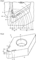
Fig. 1 is a perspective schematic view showing the configuration of a cutting tool including a cutting tool shim in the first embodiment. -
Fig. 2 is an exploded perspective schematic view showing the configuration of the cutting tool including the cutting tool shim in the first embodiment. -
Fig. 3 is an enlarged perspective schematic view of region III inFig. 1 . -
Fig. 4 is a perspective schematic view showing the configuration of the cutting tool shim in the first embodiment. -
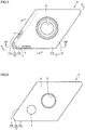
Fig. 5 is a plan schematic view showing the configuration of the cutting tool shim in the first embodiment. -
Fig. 6 is a bottom schematic view showing the configuration of the cutting tool shim in the first embodiment. -
Fig. 7 is a perspective schematic view showing the configuration of the coolant supply path of the cutting tool shim in the first embodiment. -
Fig. 8 is a cross-sectional schematic view taken along the line VIII-VIII inFig. 5 . -
Fig. 9 is a cross-sectional schematic view taken along the line IX-IX inFig. 5 . -
Fig. 10 is a cross-sectional schematic view taken along the line X-X inFig. 5 . -
Fig. 11 is a plan schematic view showing the configuration of a jetting port for an arc-shaped portion provided in the cutting tool shim in the first embodiment. -
Fig. 12 is a plan schematic view showing the configuration of a jetting port for an arc-shaped portion provided in a cutting tool shim in the second embodiment. -
Fig. 13 is a plan schematic view showing the configuration of a variation of the jetting port for the arc-shaped portion provided in the cutting tool shim in the second embodiment. -
Fig. 14 is a plan schematic view showing the configuration of a jetting port for an arc-shaped portion provided in a cutting tool shim in the third embodiment. -
Fig. 15 is a plan schematic view showing the configuration of a variation of the jetting port for the arc-shaped portion provided in the cutting tool shim in the third embodiment. -
Fig. 16 is a perspective schematic view showing the configuration of a jetting port for an arc-shaped portion provided in a cutting tool shim in the fourth embodiment. - When a jetting port provided in a shim is bought close to a cutting edge, coolant is accurately supplied to the cutting edge but cannot diffuse so widely. Accordingly, the coolant is locally jetted to the cutting edge. In other words, some parts of the cutting edge are not supplied with sufficient coolant. Local wear progresses at the parts of the cutting edge that are not supplied with sufficient coolant. In particular, at a portion around the boundary between an arc-shaped portion of the cutting edge and a linear portion continuous with the arc-shaped portion, flank face wear called boundary wear occurs. In the cutting tools disclosed in Japanese Patent Laying-Open No.
2015-217512 2015-217514 - An object of one aspect of the present invention, which has been made in view of the above problem, is to provide a cutting tool shim and a cutting tool that can reduce boundary wear.
- One aspect of the present invention can provide a cutting tool shim and a cutting tool that can reduce boundary wear.
- First, the summary of embodiments of the present invention is described.
- (1) A
cutting tool shim 10 according to one aspect of the present invention iscutting tool shim 10 to be disposed between acutting insert 20 and aholder 30 and to be fixed to holder 30.Cutting insert 20 includes aflank face 21 and arake face 22 continuous withflank face 21. The ridgeline betweenflank face 21 andrake face 22 forms acutting edge 2.Cutting edge 2 includes an arc-shaped portion 2a. Acoolant supply path 1 for jetting coolant to arc-shaped portion 2a is provided incutting tool shim 10, the coolant being supplied fromholder 30.Coolant supply path 1 includes a lead-inport 9 for leading the coolant fromholder 30 tocoolant supply path 1, and ajetting port 3 for arc-shaped portion for jetting the coolant to arc-shaped portion 2a.Jetting port 3 for arc-shaped portion has a curved shape along arc-shaped portion 2a. The distance betweenjetting port 3 for arc-shaped portion and arc-shaped portion 2a is not less than 2.2 mm and not more than 8.1 mm.
Cutting tool shim 10 according to the above (1) includesjetting port 3 for arc-shaped portion for jetting coolant to arc-shaped portion 2a ofcutting edge 2.Jetting port 3 for arc-shaped portion has a curved shape along arc-shaped portion 2a. This allows coolant to jet to arc-shaped portion 2a in the shape of layer (in the shape of curtain). Thus, coolant can be supplied over a wide region of arc-shaped portion 2a. As a result, occurrence of local wear of the cutting edge can be reduced. In particular, coolant is effectively supplied to a portion around the boundary between arc-shapedportion 2a andlinear portion 2b continuous with arc-shapedportion 2a. Accordingly, boundary wear around the boundary in the flank face can be reduced. - (2) In
cutting tool shim 10 according to the above (1), jettingport 3 for arc-shaped portion may include anouter circumference arc 3a provided along arc-shapedportion 2a, and aninner circumference arc 3b separated fromouter circumference arc 3a and provided along arc-shapedportion 2a. Thus, coolant can be supplied over a wide region of arc-shapedportion 2a. - (3) In
cutting tool shim 10 according to the above (1), jettingport 3 for arc-shaped portion may be formed by a plurality ofslits 3d provided along any of the same shape as the shape of arc-shapedportion 2a and a shape similar to the shape of arc-shapedportion 2a. Thus, coolant can be supplied over a wide region of arc-shapedportion 2a. - (4) In
cutting tool shim 10 according to any of the above (1) to (3), cuttingtool shim 10 may include atop surface 11 on which cuttinginsert 20 is to be mounted.Top surface 11 may include acontact portion 11a to come into contact with cuttinginsert 20, and a protrudingportion 11b continuous withcontact portion 11a and separated from cuttinginsert 20. Jettingport 3 for arc-shaped portion may be open at protrudingportion 11b. Thus, coolant can be effectively supplied to arc-shapedportion 2a. - (5) In
cutting tool shim 10 according to any of the above (1) to (4), cuttingedge 2 may further include alinear portion 2b continuous with arc-shapedportion 2a.Coolant supply path 1 may further include a jettingport 4b for linear portion for jetting the coolant tolinear portion 2b. Thus, coolant can be supplied tolinear portion 2b, and also to a portion around the boundary between arc-shapedportion 2a andlinear portion 2b. This can reduce wear inlinear portion 2b and can also reduce boundary wear. - (6) In
cutting tool shim 10 according to any of the above (1) to (5), cuttingtool shim 10 may have a density of not less than 99.0% and not more than 99.9%. Pores provided in cuttingtool shim 10 can reduce vibrations during cutting. - (7) In
cutting tool shim 10 according to any of the above (1) to (6), the material that constitutes cuttingtool shim 10 may have a Rockwell hardness of not less than 20 and not more than 60. A Rockwell hardness of not less than 20 can prevent a decrease in durability. A Rockwell hardness of not more than 60 can prevent deterioration in vibration damping properties. - (8) In
cutting tool shim 10 according to any of the above (1) to (7), the material that constitutes cuttingtool shim 10 may be any of a ferrous alloy and a cobalt-chromium alloy. These materials are usable as materials for a metal 3D printer. A metal 3D printer can accurately producecoolant supply path 1 that has a complex shape. - (9) In
cutting tool shim 10 according to any of the above (1) to (7), the material that constitutes cuttingtool shim 10 may be a polycrystal. - (10) In
cutting tool shim 10 according to the above (9), the polycrystal may have a particle diameter of not less than 4 µm and not more than 10 µm. - (11) In
cutting tool shim 10 according to any of the above (1) to (10), the distance between the jetting port for arc-shaped portion and the arc-shaped portion may be not less than 3.0 mm and not more than 6.5 mm. - (12) In
cutting tool shim 10 according to the above (11), the distance between the jetting port for arc-shaped portion and the arc-shaped portion may be not less than 3.8 mm and not more than 4.9 mm. - (13) A
cutting tool 100 according to one aspect of the present invention comprises cuttingtool shim 10 according to any of the above (1) to (12), cuttinginsert 20, andholder 30. This can reduce boundary wear. - The details of embodiments of the present invention are hereinafter described with reference to the drawings. In the drawings, identical or corresponding parts are identically denoted, and the description thereof is not repeated.
- First, the configuration of a cutting tool including a cutting tool shim in the first embodiment is described.
- As shown in
Fig. 1 andFig. 2 , acutting tool 100 mainly includes a cutting tool shim 10 (hereinafter also referred to as a shim), a cuttinginsert 20, aholder 30, afixation portion 40, afirst fastening portion 50, and asecond fastening portion 60.Holder 30 includes aseating surface 34, aside surface 35, and anupper surface 36. Seatingsurface 34 has afirst fastening hole 31 and acoolant supply hole 32.Upper surface 36 has asecond fastening hole 33.Side surface 35 extends in a direction that intersects both seatingsurface 34 andupper surface 36.Side surface 35 is continuous with both seatingsurface 34 andupper surface 36. -
Shim 10 is disposed between cuttinginsert 20 andholder 30.Shim 10 has a first through-hole 14.First fastening portion 50 is inserted in first through-hole 14.First fastening portion 50 is screwed intofirst fastening hole 31, thus fixingshim 10 toholder 30.Fixation portion 40 is disposed onupper surface 36 ofholder 30. The tip offixation portion 40 is disposed in a second through-hole 24 provided in cuttinginsert 20.Fixation portion 40 partially covers the upper surface of cuttinginsert 20.Fixation portion 40 has a third through-hole 44.Second fastening portion 60 is disposed in third through-hole 44 and screwed intosecond fastening hole 33 provided inupper surface 36, thus fixingfixation portion 40 toholder 30.Fixation portion 40fixes cutting insert 20. - As shown in
Fig. 3 , cuttinginsert 20 includes aflank face 21, and arake face 22 continuous withflank face 21. The ridgeline betweenflank face 21 and rake face 22 forms acutting edge 2. Flank face 21 extends from cuttingedge 2 towardshim 10. Rake face 22 is a face opposite to the face of cuttinginsert 20 in contact withshim 10. Cuttingedge 2 includes an arc-shapedportion 2a, a firstlinear portion 2b, and a secondlinear portion 2c. Firstlinear portion 2b and secondlinear portion 2c are each continuous with arc-shapedportion 2a. Arc-shapedportion 2a connects firstlinear portion 2b and secondlinear portion 2c. The arc-shaped portion mainly corresponds to the main cutting edge (the cutting edge that plays a major role for generating chips in cutting). In a portion around the boundaries between the arc-shaped portion and the linear portions, the tool advancing side mainly corresponds to the front cutting edge (generally, the cutting edge remote from the finished surface). In a portion around the boundaries between the arc-shaped portion and the linear portions, the side opposite to the tool advancing side mainly corresponds to the side cutting edge (generally, the cutting edge that forms the finished surface). - Flank face 21 has a first
curved portion 21a, afirst plane portion 21b, and asecond plane portion 21c.First plane portion 21b andsecond plane portion 21c are each continuous with firstcurved portion 21a. Firstcurved portion 21a connectsfirst plane portion 21b andsecond plane portion 21c. Arc-shapedportion 2a is the ridgeline between firstcurved portion 21a and rakeface 22. Firstlinear portion 2b is the ridgeline betweenfirst plane portion 21b and rakeface 22. Secondlinear portion 2c is the ridgeline betweensecond plane portion 21c and rakeface 22. The angle between the straight line along firstlinear portion 2b and the straight line along secondlinear portion 2c may be smaller than 90°. The angle betweenfirst plane portion 21b and rakeface 22 may be smaller than 90°. Similarly, the angle betweensecond plane portion 21c and rakeface 22 may be smaller than 90°. - With reference to
Fig. 4 ,Fig. 5, and Fig. 6 ,shim 10 has atop surface 11, abottom surface 12, and aside surface 13.Bottom surface 12 is on the side opposite totop surface 11.Side surface 13 is continuous with bothtop surface 11 andbottom surface 12.Side surface 13 connectstop surface 11 andbottom surface 12.Side surface 13 has a secondcurved portion 13a, athird plane portion 13b, and afourth plane portion 13c. Ontop surface 11, cuttinginsert 20 is to be mounted. In other words,top surface 11 comes into contact with the bottom surface of cuttinginsert 20. As shown inFig. 5 ,top surface 11 has acontact portion 11a to come into contact with cuttinginsert 20, and a protrudingportion 11b continuous withcontact portion 11a and separated from cuttinginsert 20. First through-hole 14 is open at bothtop surface 11 andbottom surface 12. - The material that constitutes
shim 10 is, for example, a ferrous alloy and a cobalt-chromium alloy. The ferrous alloy is, for example, maraging steel, stainless steel (SUS316), or the like. The material that constitutesshim 10 is a formed body obtained by, for example, powder metallurgy, 3D printer, or cutting from a metal body. The material that constitutesshim 10 may be a single crystal or a polycrystal. The polycrystal is, for example, a metallic formed body obtained by powder metallurgy. The particle diameter of the polycrystal is, for example, not less than 4 µm and not more than 10 µm. The upper limit of the particle diameter may be 9 µm or may be 8 µm. The lower limit of the particle diameter may be 5 µm or may be 6 µm. The material that constitutesshim 10 is not limited to metal but may be any other material that can serve as a shim. In terms of workability and durability, the material that constitutesshim 10 is preferably a ferrous alloy and a cobalt-chromium alloy. - Next, a method of measuring the particle diameter is described. First, ion milling is performed using a cross section polisher (CP) to form a CP work surface of a shim. Then, the CP work surface is photographed using a scanning electron microscope (SEM), and the structure of the shim is observed. The analytical method is electron back-scatter diffraction (EBSD) analysis. The accelerating voltage is 15 kV. A photograph is taken with a magnification of 500 times. Based on the difference in crystal orientation of each crystal in the polycrystal, the grain boundary is observed and the particle diameter is measured.
- For example, a metal 3D printer can be used to produce
shim 10. Specifically, shim 10 is produced by heating metallic powder by laser. Thus, pores can be formed inshim 10. The density ofshim 10 is less than 100%. Specifically, the density ofshim 10 is, for example, not less than 99.00% and not more than 99.99%. The upper limit of the density may be 99.95% or may be 99.90%. The lower limit of the density may be 99.10% or may be 99.20%. The density ofshim 10 being less than 100% (that is, pores being present in the shim) enhances the vibration damping properties. - Next, a method of measuring the shim density is described. First, ion milling is performed using a cross section polisher to form a CP work surface of a shim. Then, the CP work surface is photographed using a scanning electron microscope (SEM) to provide a two-dimensional structure photograph of the shim with a magnification of 100 times. Pores in the structure are identified using image processing software (WinROOF Ver.7.4.1) manufactured by Mitani Corporation. Specifically, the region with pores and the region without pores are determined by performing conversion to binary on the structure photograph. The shim density is determined as ([the total area of the measurement field] - [the area of pores]) / (the total area of the measurement field). If no pores are present in the shim, the shim density is 100%.
- The Rockwell hardness of the material that constitutes
shim 10 may be, for example, not less than 20 and not more than 60. The upper limit of the Rockwell hardness may be 58 or may be 56. The lower limit of the Rockwell hardness may be 22 or may be 24. The Rockwell hardness is determined by, for example, measuring Rockwell hardness C scale (HRC) in accordance with the method provided in Japan Industrial Standard (JIS Z 2245). Specifically, a sample is indented with a conical diamond indenter, and the permanent indentation depth h (mm) is measured. The test force is 10 kgf. The additional test force is 140 kgf. The total test force is 150 kgf. The HRC is calculated in accordance with the followingnumerical formula 1. Note that the international standard equivalent to Japan Industrial Standard (JIS Z 2245) is ISO 6508-1.
- As shown in
Fig. 7 , acoolant supply path 1 is provided inshim 10.Coolant supply path 1 is for jetting coolant, which is supplied fromholder 30, to cuttingedge 2.Coolant supply path 1 includes a lead-inport 9, a jettingport 3 for arc-shaped portion, a jettingport 4b for first linear portion, and a jettingport 4c for second linear portion. Lead-inport 9 is for leading coolant fromholder 30 intocoolant supply path 1. Lead-inport 9 communicates withcoolant supply hole 32 provided inseating surface 34 ofholder 30. Jettingport 3 for arc-shaped portion is for jetting coolant to arc-shapedportion 2a. The distance between jettingport 3 for arc-shaped portion and arc-shapedportion 2a is, for example, about not less than 2.2 mm and not more than 8.1 mm. The distance between jettingport 3 for arc-shaped portion and arc-shapedportion 2a is the distance between jettingport 3 for arc-shaped portion and arc-shapedportion 2a in the direction perpendicular totop surface 11. The distance between jettingport 3 for arc-shaped portion and arc-shapedportion 2a may be not less than 3.0 mm and not more than 6.5 mm, or may be not less than 3.8 mm and not more than 4.9 mm. Jettingport 4b for first linear portion is for jetting coolant to firstlinear portion 2b. Similarly, jettingport 4c for second linear portion is for jetting coolant to secondlinear portion 2c. - As shown in
Fig. 5 , jettingport 3 for arc-shaped portion, jettingport 4b for first linear portion, and jettingport 4c for second linear portion are open at protrudingportion 11b oftop surface 11. First through-hole 14 is open atcontact portion 11a. As shown inFig. 6 , lead-inport 9 is open at, for example,bottom surface 12. However, lead-inport 9 may be open at a surface other thanbottom surface 12. Lead-inport 9 may be open at, for example,side surface 13. - As shown in
Fig. 7, Fig. 8 ,Fig. 9, and Fig. 10 ,coolant supply path 1 further includes avertical pathway 5, a firstlateral pathway 6b, a secondlateral pathway 6c, afirst oblique pathway 7b, asecond oblique pathway 7c, and acentral pathway 8. As shown inFig. 8 ,vertical pathway 5 is continuous with jettingport 3 for arc-shaped portion. As shown inFig. 7 ,vertical pathway 5 is continuous with firstlateral pathway 6b and secondlateral pathway 6c. As shown inFig. 8 ,first oblique pathway 7b is continuous with jettingport 4b for first linear portion andcentral pathway 8. Similarly,second oblique pathway 7c is continuous with jettingport 4c for second linear portion andcentral pathway 8. As shown inFig. 8 andFig. 9 ,vertical pathway 5 extends in the direction perpendicular totop surface 11. Each of firstlateral pathway 6b and secondlateral pathway 6c extends in the direction parallel totop surface 11. As shown inFig. 7 and Fig. 8 , each of firstoblique pathway 7b andsecond oblique pathway 7c extends obliquely with respect totop surface 11. As shown inFig. 10 ,central pathway 8 is continuous with bothfirst oblique pathway 7b andsecond oblique pathway 7c. - The arrows in
Fig. 7 to Fig. 10 represent the flow of coolant. Coolant supplied fromholder 30 passes through lead-inport 9 to be led intocentral pathway 8. Part of the coolant branches fromcentral pathway 8 into firstlateral pathway 6b and secondlateral pathway 6c, and they join together atvertical pathway 5. Part of the coolant passes throughvertical pathway 5 and jets from jettingport 3 for arc-shaped portion to arc-shapedportion 2a in the shape of curtain (in the shape of layer). The other part of the coolant branches fromcentral pathway 8 intofirst oblique pathway 7b andsecond oblique pathway 7c. The coolant that has passed throughfirst oblique pathway 7b jets from jettingport 4b for first linear portion to firstlinear portion 2b in the shape of curtain (in the shape of layer). Similarly, the coolant that has passed throughsecond oblique pathway 7c jets from jettingport 4c for second linear portion to secondlinear portion 2c in the shape of curtain (in the shape of layer). - Next, the shape of the jetting port for arc-shaped portion is described in detail.
- As shown in
Fig. 11 , jettingport 3 for arc-shaped portion has a curved shape along arc-shapedportion 2a.Broken line 2d shows the same shape as arc-shapedportion 2a of cuttingedge 2 of cuttinginsert 20. The curved shape along arc-shapedportion 2a includes an opening curved alongbroken line 2a. Specifically, as shown inFig. 11 , as seen in the direction perpendicular totop surface 11, the region surrounded by jettingport 3 for arc-shaped portion coincides withbroken line 2d. Jettingport 3 for arc-shaped portion may surroundbroken line 2d. Arc-shapedportion 2a may have a curved shape formed by arcs having different curvatures continuous with each other. - Jetting
port 3 for arc-shaped portion may be a single hole having anouter circumference arc 3a, aninner circumference arc 3b, and aconnection portion 3c.Outer circumference arc 3a is provided along arc-shapedportion 2a.Inner circumference arc 3b is separated fromouter circumference arc 3a and provided along arc-shapedportion 2a.Connection portion 3c connectsouter circumference arc 3a andinner circumference arc 3b.Inner circumference arc 3b may be smaller thanouter circumference arc 3a in radius of curvature.Outer circumference arc 3a is located betweeninner circumference arc 3b and secondcurved portion 13a. Jettingport 3 for arc-shaped portion is preferably smaller than lead-inport 9 in area. This allows coolant to jet from jettingport 3 for arc-shaped portion at a high pressure. - Next, the shapes of the jetting port for first linear portion and the jetting port for second linear portion are described in detail.
- Jetting
port 4b for first linear portion extends, for example, along a straight line parallel to firstlinear portion 2b. Jettingport 4b for first linear portion may be a single hole, or may be a plurality of slits disposed at intervals along a straight line. Similarly, jettingport 4c for second linear portion extends, for example, along a straight line parallel to secondlinear portion 2c. Jettingport 4c for second linear portion may be a single hole, or may be a plurality of slits disposed at intervals along a straight line. - Next, the advantageous effects of the cutting tool shim and the cutting tool in the first embodiment are described.
- Cutting
tool shim 10 for the cutting tool in the first embodiment includes jettingport 3 for arc-shaped portion for jetting coolant to arc-shapedportion 2a of cuttingedge 2. Jettingport 3 for arc-shaped portion has a curved shape along arc-shapedportion 2a. This allows coolant to jet to arc-shapedportion 2a in the shape of layer (in the shape of curtain). Thus, coolant can be supplied over a wide region of arc-shapedportion 2a. As a result, occurrence of local wear of the cutting edge can be reduced. In particular, coolant is supplied to a portion around the boundary between arc-shapedportion 2a andlinear portion 2b continuous with arc-shapedportion 2a. Accordingly, boundary wear around the boundary in the flank face can be reduced. Further, since the jetting port is provided in the shim, the jetting port can be brought closer to the edge of the cutting tool than when a jetting port is provided in the holder. This can shorten the distance between jettingport 3 for arc-shaped portion and arc-shapedportion 2a of cuttingedge 2. As a result, coolant can accurately jet to arc-shapedportion 2a. Further, the mechanism which jets coolant from the shim, not from the holder body, allows easy replacement. - Further, in
shim 10 in the first embodiment, jettingport 3 for arc-shaped portion includesouter circumference arc 3a provided along arc-shapedportion 2a, andinner circumference arc 3b separated fromouter circumference arc 3a and provided along arc-shapedportion 2a. Thus, coolant can be supplied over a wide region of arc-shapedportion 2a. - Further, shim 10 in the first embodiment includes
top surface 11 on which cuttinginsert 20 is to be mounted.Top surface 11 hascontact portion 11a to come into contact with cuttinginsert 20, and protrudingportion 11b continuous withcontact portion 11a and separated from cuttinginsert 20. Jettingport 3 for arc-shaped portion is open at protrudingportion 11b. Thus, coolant can be effectively supplied to arc-shapedportion 2a. - Further, according to
shim 10 in the first embodiment, cuttingedge 2 further includeslinear portion 2b continuous with arc-shapedportion 2a.Coolant supply path 1 further includes jettingport 4b for linear portion for jetting coolant tolinear portion 2b. Thus, coolant can be supplied tolinear portion 2b, and also to a portion around the boundary between arc-shapedportion 2a andlinear portion 2b. This can reduce wear inlinear portion 2b and can also reduce boundary wear. - Further, according to
shim 10 in the first embodiment, the density ofshim 10 is not less than 99.0% and not more than 99.9%. Pores provided inshim 10 can reduce vibrations during cutting. - Further, according to
shim 10 in the first embodiment, the material that constitutesshim 10 is any one of a ferrous alloy and a cobalt-chromium alloy. These materials are usable as materials for a metal 3D printer. A metal 3D printer can accurately producecoolant supply path 1 that has a complex shape. - Next, the configurations of a cutting tool and a shim therefor in the second embodiment are described. The following mainly describes the differences from the cutting tool and the shim therefor in the first embodiment, and redundant description is not repeated.
- Jetting
port 3 for arc-shaped portion has a curved shape along arc-shapedportion 2a. As shown inFig. 12 , the curved shape along arc-shapedportion 2a includes an opening formed by a plurality ofslits 3d provided alongbroken line 2d, which is in the same shape as that of arc-shapedportion 2a. In this configuration, jettingport 3 for arc-shaped portion is formed by a plurality ofslits 3d. The plurality ofslits 3d are separated from one another. Each of the plurality ofslits 3d is, for example, circular in shape. As shown inFig. 13 , each of the plurality ofslits 3d may be rectangular in shape. Eachslit 3d may have any other shape, such as an ellipse, a regular square, or a polygon. The total area ofslits 3d which form jettingport 3 for arc-shaped portion is preferably smaller than the area of lead-inport 9. If lead-inport 9 includes a plurality of lead-in slits corresponding the plurality of jetting slits, each of the plurality of jetting slits is preferably smaller in area than a corresponding one of the plurality of lead-in slits. This allows coolant to jet from eachslit 3d at a high pressure. The cutting tool in the second embodiment provides the same advantageous effects as those of the cutting tool in the first embodiment. - Next, the configurations of a cutting tool and a shim therefor in the third embodiment are described. The following mainly describes the differences from the cutting tool and the shim therefor in the first embodiment, and redundant description is not repeated.
- As shown in
Fig. 14 andFig. 15 , jettingport 3 for arc-shaped portion may be formed by a plurality ofslits 3d provided along a shape similar to the shape of arc-shapedportion 2a. A shape similar to the shape of arc-shapedportion 2a refers to the same, geometrically similar shape to the shape of arc-shapedportion 2a. InFig. 14 ,broken line 2f shows the same shape as, but scaled down from arc-shapedportion 2a. The center of the circle alongbroken line 2f coincides with the center of the circle alongbroken line 2d. As shown inFig. 14 , a plurality ofslits 3d may be provided alongbroken line 2f. InFig. 15 ,broken line 2e shows the same shape as, but scaled up from arc-shapedportion 2a. The center of the circle alongbroken line 2e coincides with the center of the circle alongbroken line 2d. As shown inFig. 15 , a plurality ofslits 3d may be provided alongbroken line 2e. Alternatively, a single, curved jettingport 3 for arc-shaped portion may be provided alongbroken line 2f orbroken line 2e. The cutting tool in the third embodiment provides the same advantageous effects as those of the cutting tool in the first embodiment. - Next, the configurations of a cutting tool and a shim therefor in the fourth embodiment are described. The following mainly describes the differences from the cutting tool and the shim therefor in the first embodiment, and redundant description is not repeated.
- As shown in
Fig. 16 ,shim 10 may include astand portion 15.Stand portion 15 forms a part of secondcurved portion 13a and protrudes in the direction perpendicular totop surface 11. Theupper surface 11c ofstand portion 15 is a part oftop surface 11.Upper surface 11c is closer to rakeface 22 of cuttinginsert 20 than protrudingportion 11b is. Jettingport 3 for arc-shaped portion may be provided inupper surface 11c ofstand portion 15. This allows jettingport 3 for arc-shaped portion to be brought closer to arc-shapedportion 2a of cuttinginsert 20. The cutting tool in the fourth embodiment provides the same advantageous effects as those of the cutting tool in the first embodiment. - First, shims of samples 1-1 to 1-9 were prepared. The shims of samples 1-1 to 1-6 are the present examples. The shims of samples 1-7 to 1-9 are comparative examples. The material of the shims of samples 1-1, 1-2 and 1-8 was maraging steel. The material of the shims of samples 1-3 and 1-4 was SUS316. The material of the shims of samples 1-5 and 1-6 was Co-Cr alloy. The material of the shim of sample 1-7 was cemented carbide. The material of the shim of sample 1-9 was SUS304. The shim density of samples 1-1 to 1-6 was not less than 99.25% and less than 99.99%. The shim density of samples 1-7 to 1-9 was not less than 99.99% and not more than 100%.
- A cutting holder having an acceleration sensor attached to its bottom surface was fixed to a turret of a machine tool. A shim and a cutting insert were attached to the cutting holder. The edge of the cutting insert was vibrated with a force of 200 N using an impulse hammer. The change of the vibration acceleration (mm/s2) with respect to time was measured by the acceleration sensor. The time (t1 - t0) from the point of time (t0), at which the vibration acceleration had the maximum amplitude, to the point of time (t1), at which the amplitude of the vibration acceleration became equal to or less than 0.01 times the maximum amplitude for the first time, was calculated as the vibration damping time.
-
[Table 1] Material of Shim Density (%) Vibration Damping Time (µs) Sample 1-1 maraging steel 99.25 5.1 Sample 1-2 maraging steel 99.91 5.4 Sample 1-3 SUS316 99.30 5.3 Sample 1-4 SUS316 99.97 5.8 Sample 1-5 Co-Cr alloy 99.33 5.2 Sample 1-6 Co-Cr alloy 99.61 5.6 Sample 1-7 cemented carbide 99.99 9.5 Sample 1-8 maraging steel 100 8.2 Sample 1-9 SUS304 100 8.8 - As shown in Table 1, the vibration damping time in the case of the shims of samples 1-1 to 1-6 was not less than 5.1 µs and not more than 5.8 µs, whereas the vibration damping time in the case of the shims of samples 1-7 to 1-9 was not less than 8.2 µs and not more than 9.5 µs. In the case of the shims of samples 1-1 to 1-6, the vibration damping time was shorter than in the case of the shims of samples 1-7 to 1-9. Thus, it is shown that a shim density of less than 99.99% remarkably enhances the vibration damping properties regardless of the material of the shim. It is also shown that, with the same material, a lower shim density makes the vibration damping time shorter.
- First, cutting tools of samples 2-1 to 2-5 were prepared. The cutting tools of samples 2-1 to 2-3 are the present examples. The cutting tools of samples 2-4 and 2-5 are comparative examples. For the cutting tools of samples 2-1 to 2-3, cutting oil was jetted from a shim through a holder. For the cutting tool of sample 2-4, cutting oil was jetted from the bottom surface of a holder through the holder. For the cutting tool of sample 2-5, cutting oil was jetted from outside.
- For the cutting tools of samples 2-1 and 2-2, the jetting port was in the shape of an arc. For the cutting tool of sample 2-3, the jetting port was in the shape of a plurality of circular holes arranged in an arc. For the cutting tools of samples 2-4 and 2-5, the jetting port was in the shape of a single circular hole. For the cutting tool of sample 2-1, the oiling pressure was 1.5 MPa. For the cutting tools of samples 2-2 to 2-4, the oiling pressure was 7 MPa. For the cutting tool of sample 2-5, the oiling pressure was 0.15 MPa.
- A work material made of inconel 718 was cut 1 km using the cutting tools of samples 2-1 to 2-5. Then, the flank face wear volume and the boundary wear volume of cutting insert were measured. The cutting speed (Vc) was 200 m/min. The feed rate (f) was 0.2 mm/rotation. The depth of cut (ap) was 0.2 mm. Each cutting insert was a CBN sintered body, BN7000 manufactured by Sumitomo Electric Hardmetal Corporation. The CBN content in the CBN sintered body was 90% by volume, with a WC-Co binder being added.
-
[Table 2] Oiling System for Cutting Oil Jetting Port Shape Oiling Pressure Flank Face Wear Volume After Cutting 1 km (mm) Boundary Wear Volume After Cutting 1 km (mm) Sample 2-1 jet from shim through holder arc shape 1.5 MPa 0.056 0.068 Sample 2-2 jet from shim through holder arc shape 7 MPa 0.041 0.051 Sample 2-3 jet from shim through holder arrange a plurality of circular holes in arc shape 7 MPa 0.043 0.055 Sample 2-4 jet from holder bottom surface through holder circular hole 7 MPa 0.115 0.133 Sample 2-5 oil from outside circular hole 0.15 MPa 0.188 0.243 - As shown in Table 2, in the case of the cutting tools of samples 2-1 to 2-3, the flank face wear volume and the boundary wear volume of cutting insert were respectively not less than 0.041 mm and not more than 0.056 mm, and not less than 0.051 mm and not more than 0.068 mm; whereas in the case of the cutting tools of samples 2-4 and 2-5, the flank face wear volume and the boundary wear volume of cutting insert were respectively not less than 0.115 mm and not more than 0.188 mm, and not less than 0.133 mm and not more than 0.243 mm. This result shows that cutting fluid jetted from a shim can remarkably reduce the flank face wear volume and the boundary wear volume of cutting insert.
- In the case of the cutting tool of sample 2-2, the flank face wear volume and the boundary wear volume of cutting insert were smaller than in the case of the cutting tool of sample 2-1. This result shows that a higher oiling pressure can reduce the flank face wear volume and the boundary wear volume of cutting insert. Further, the flank face wear volume and the boundary wear volume of cutting insert in the case of the cutting tool of sample 2-2 were substantially the same as the flank face wear volume and the boundary wear volume of cutting insert in the case of the cutting tool of sample 2-3. This result shows that a jetting port formed by a plurality of circular holes arranged in an arc shape has the same advantageous effects as those of an arc-shaped jetting port.
- A work material made of titanium alloy (Ti-6Al-4V) was cut 1 km using the cutting tools of samples 2-1 to 2-5. Then, the flank face wear volume and the boundary wear volume of cutting insert were measured. The cutting speed (Vc) was 100 m/min. The feed rate (f) was 0.1 mm/rotation. The depth of cut (ap) was 0.2 mm. Each cutting insert was a CBN sintered body, BN7000 manufactured by Sumitomo Electric Hardmetal Corporation. The CBN content in the CBN sintered body was 90% by volume, with a WC-Co binder being added.
-
[Table 3] Oiling System for Cutting Oil Jetting Port Shape Oiling Pressure Flank Face Wear Volume After Cutting 1 km (mm) Boundary Wear Volume After Cutting 1 km (mm) Sample 2-1 jet from shim through holder arc shape 1.5 MPa 0.044 none Sample 2-2 jet from shim through holder arc shape 7 MPa 0.039 none Sample 2-3 jet from shim through holder arrange a plurality of circular holes in arc shape 7 MPa 0.038 none Sample 2-4 jet from holder bottom surface through holder one circular hole 7 MPa 0.061 0.089 Sample 2-5 oil from outside one circular hole 0.15 MPa 0.119 0.158 - As shown in Table 3, in the case of the cutting tools of samples 2-1 to 2-3, the flank face wear volume of cutting insert was not less than 0.038 mm and not more than 0.044 mm; whereas in the case of the cutting tools of samples 2-4 and 2-5, the flank face wear volume of cutting insert was not less than 0.061 mm and not more than 0.119 mm. Further, in the case of the cutting tools of samples 2-1 to 2-3, the boundary wear did not occur in the cutting insert; whereas in the case of the cutting tools of samples 2-4 and 2-5, the boundary wear of not less than 0.089 mm and not more than 0.158 mm occurred in the cutting insert. These results show that cutting fluid jetted from a shim can remarkably reduce the flank face wear volume of cutting insert and reduce occurrence of the boundary wear.
- Further, in the case of the cutting tool of sample 2-2, the flank face wear volume of cutting insert was smaller than in the case of the cutting tool of sample 2-1. This result shows that a higher oiling pressure can reduce the flank face wear volume of cutting insert. Further, the flank face wear volume of cutting insert in the case of the cutting tool of sample 2-2 was substantially the same as the flank face wear volume of cutting insert in the case of the cutting tool of sample 2-3. This result shows that a jetting port formed by a plurality of circular holes arranged in an arc shape has the same advantageous effects as those of an arc-shaped jetting port.
- First, cutting tools of samples 3-1 to 3-8 were prepared. The cutting tools of samples 3-1 to 3-5 are the present examples. The cutting tools of samples 3-6 to 3-8 are comparative examples. For the cutting tools of samples 3-1 to 3-6, cutting oil was jetted from a shim through a holder. For the cutting tools of samples 3-7 and 3-8, cutting oil was jetted from the bottom surface of a holder through the holder. The distances between the jetting ports and the edges for the cutting tools of samples 3-1 to 3-8 were respectively 2.2 mm, 3.0 mm, 3.8 mm, 4.9 mm, 8.1 mm, 1.0 mm, 10 mm, and 20 mm. For the cutting tools for all the samples, the oiling pressure was 7 MPa.
- A work material made of inconel 718 was cut 1 km using the cutting tools of samples 3-1 to 3-8. Then, the flank face wear volume and the boundary wear volume of cutting insert were measured. The cutting speed (Vc) was 200 m/min. The feed rate (f) was 0.2 mm/rotation. The depth of cut (ap) was 0.2 mm. Each cutting insert was a CBN sintered body, BN7000 manufactured by Sumitomo Electric Hardmetal Corporation.
-
[Table 4] Distance Between Jetting Port and Edge (mm) Oiling System for Cutting Oil Oiling Pressure Flank Face Wear Volume After Cutting 1 km (mm) Boundary Wear Volume After Cutting 1 km (mm) Sample 3-1 2.2 jet from shim through holder 7 MPa 0.053 0.061 Sample 3-2 3.0 jet from shim through holder 7 MPa 0.044 0.057 Sample 3-3 3.8 jet from shim through holder 7 MPa 0.041 0.048 Sample 3-4 4.9 jet from shim through holder 7 MPa 0.043 0.050 Sample 3-5 8.1 jet from shim through holder 7 MPa 0.050 0.062 Sample 3-6 1.0 jet from shim through holder 7 MPa 0.047 0.091 Sample 3-7 10 jet from holder bottom surface through holder 7 MPa 0.078 0.086 Sample 3-8 20 jet from holder bottom surface through holder 7 MPa 0.106 0.089 - As shown in Table 4, in the case of the cutting tools of samples 3-1 to 3-5, the boundary wear volume of cutting insert was not less than 0.048 mm and not more than 0.062 mm; whereas in the case of the cutting tools of samples 3-6 to 3-8, the boundary wear volume of cutting insert was not less than 0.086 mm and not more than 0.091 mm. This result shows that the boundary wear volume of cutting insert can be remarkably reduced by setting the distance between the jetting port and the edge to not less than 2.2 mm and not more than 8.1 mm. It is also shown that the boundary wear volume of cutting insert can further be reduced by setting the distance between the jetting port and the edge to not less than 3.0 mm and not more than 4.9 mm.
- In the case of the cutting tools of samples 3-1 to 3-6, the flank face wear volume of cutting insert was not less than 0.041 mm and not more than 0.053 mm; whereas in the case of the cutting tools of samples 3-7 and 3-8, the boundary wear volume of cutting insert was not less than 0.078 mm and not more than 0.106 mm. This result shows that cutting oil jetted from a shim can reduce the flank face wear volume of cutting insert more effectively than cutting oil jetted from the bottom surface of a holder.
- It should be construed that the embodiments and the examples disclosed herein are given by way of example in every respect, not by way of limitation. It is intended that the scope of the present invention is defined by the claims, not by the above-described embodiments, and includes any modification equivalent in meaning and scope to the claims.
- 1: coolant supply path; 2: cutting edge; 2a: arc-shaped portion; 2b: first linear portion (linear portion); 2c: second linear portion; 2d, 2e, 2f: broken line; 3: jetting port for arc-shaped portion; 3D: metal; 3a: outer circumference arc; 3b: inner circumference arc; 3c: connection portion; 3d: slit; 4b: jetting port for first linear portion (jetting port for linear portion); 4c: jetting port for second linear portion; 5: vertical pathway; 6b: first lateral pathway; 6c: second lateral pathway; 7b: first oblique pathway; 7c: second oblique pathway; 8: central pathway; 9: lead-in port; 10: cutting tool shim (shim); 11: top surface; 11a: contact portion; 11b: protruding portion; 11c, 36: upper surface; 12: bottom surface; 13, 35: side surface; 13a: second curved portion; 13b: third plane portion; 13c: fourth plane portion; 14: first through-hole; 15: stand portion; 20: cutting insert; 21: flank face; 21a: first curved portion; 21b: first plane portion; 21c: second plane portion; 22: rake face; 24: second through-hole; 30: holder; 31: first fastening hole; 32: coolant supply hole; 33: second fastening hole; 34: seating surface; 40: fixation portion; 44: third through-hole; 50: first fastening portion; 60: second fastening portion; 100: cutting tool
Claims (13)
- A cutting tool shim to be disposed between a cutting insert and a holder and to be fixed to the holder,
the cutting insert including a flank face and a rake face continuous with the flank face,
a ridgeline between the flank face and the rake face forming a cutting edge, the cutting edge including an arc-shaped portion,
a coolant supply path for jetting coolant to the arc-shaped portion being provided in the cutting tool shim, the coolant being supplied from the holder,
the coolant supply path includinga lead-in port for leading the coolant from the holder to the coolant supply path, anda jetting port for arc-shaped portion for jetting the coolant to the arc-shaped portion,the jetting port for arc-shaped portion having a curved shape along the arc-shaped portion,
a distance between the jetting port for arc-shaped portion and the arc-shaped portion being not less than 2.2 mm and not more than 8.1 mm. - The cutting tool shim according to claim 1, wherein
the jetting port for arc-shaped portion includesan outer circumference arc provided along the arc-shaped portion, andan inner circumference arc separated from the outer circumference arc and provided along the arc-shaped portion. - The cutting tool shim according to claim 1, wherein
the jetting port for arc-shaped portion is formed by a plurality of slits provided along any ofa same shape as a shape of the arc-shaped portion, anda shape similar to the shape of the arc-shaped portion. - The cutting tool shim according to any one of claims 1 to 3, wherein
the cutting tool shim includes a top surface on which the cutting insert is to be mounted,
the top surface includesa contact portion to come into contact with the cutting insert, anda protruding portion continuous with the contact portion and separated from the cutting insert, andthe jetting port for arc-shaped portion is open at the protruding portion. - The cutting tool shim according to any one of claims 1 to 4, wherein
the cutting edge further includes a linear portion continuous with the arc-shaped portion, and
the coolant supply path further includes a jetting port for linear portion for jetting the coolant to the linear portion. - The cutting tool shim according to any one of claims 1 to 5, wherein the cutting tool shim has a density of not less than 99.0% and not more than 99.9%.
- The cutting tool shim according to any one of claims 1 to 6, wherein a material that constitutes the cutting tool shim has a Rockwell hardness of not less than 20 and not more than 60.
- The cutting tool shim according to any one of claims 1 to 7, wherein a material that constitutes the cutting tool shim is any of a ferrous alloy and a cobalt-chromium alloy.
- The cutting tool shim according to any one of claims 1 to 7, wherein a material that constitutes the cutting tool shim is a polycrystal.
- The cutting tool shim according to claim 9, wherein the polycrystal has a particle diameter of not less than 4 µm and not more than 10 µm.
- The cutting tool shim according to any one of claims 1 to 10, wherein the distance between the jetting port for arc-shaped portion and the arc-shaped portion is not less than 3.0 mm and not more than 6.5 mm.
- The cutting tool shim according to claim 11, wherein the distance between the jetting port for arc-shaped portion and the arc-shaped portion is not less than 3.8 mm and not more than 4.9 mm.
- A cutting tool comprising:the cutting tool shim according to any one of claims 1 to 12;the cutting insert; andthe holder.
Applications Claiming Priority (2)
| Application Number | Priority Date | Filing Date | Title |
|---|---|---|---|
| JP2016161273A JP2018027605A (en) | 2016-08-19 | 2016-08-19 | Cutting plate and cutting tool |
| PCT/JP2017/027630 WO2018034133A1 (en) | 2016-08-19 | 2017-07-31 | Cutting tool base, and cutting tool |
Publications (3)
| Publication Number | Publication Date |
|---|---|
| EP3501700A1 true EP3501700A1 (en) | 2019-06-26 |
| EP3501700A4 EP3501700A4 (en) | 2020-04-08 |
| EP3501700B1 EP3501700B1 (en) | 2025-08-20 |
Family
ID=61196670
Family Applications (1)
| Application Number | Title | Priority Date | Filing Date |
|---|---|---|---|
| EP17841360.5A Active EP3501700B1 (en) | 2016-08-19 | 2017-07-31 | Cutting tool with a cutting tool shim |
Country Status (6)
| Country | Link |
|---|---|
| US (1) | US11065693B2 (en) |
| EP (1) | EP3501700B1 (en) |
| JP (1) | JP2018027605A (en) |
| KR (1) | KR20190042003A (en) |
| CN (1) | CN109641281A (en) |
| WO (1) | WO2018034133A1 (en) |
Cited By (4)
| Publication number | Priority date | Publication date | Assignee | Title |
|---|---|---|---|---|
| GB2584296A (en) * | 2019-05-28 | 2020-12-02 | Gkn Aerospace Sweden Ab | An apparatus and method for machining an aeronautical component |
| EP3919211A1 (en) * | 2020-06-02 | 2021-12-08 | Ceratizit Luxembourg Sàrl | Milling tool, use thereof and milling process |
| EP3960345A1 (en) * | 2020-08-21 | 2022-03-02 | Západoceská univerzita v Plzni | Cutting tool |
| CZ309670B6 (en) * | 2022-07-14 | 2023-06-28 | České vysoké učení technické v Praze | A cutting tool |
Families Citing this family (11)
| Publication number | Priority date | Publication date | Assignee | Title |
|---|---|---|---|---|
| US11890684B2 (en) * | 2016-12-01 | 2024-02-06 | Seco Tools Ab | Anvil with curved passage for cutting tool |
| EP3330024B1 (en) * | 2016-12-01 | 2021-04-28 | Seco Tools Ab | Cutting tool having an anvil with curved passage and method for making such a cutting tool |
| JP6651136B2 (en) * | 2017-10-25 | 2020-02-19 | 株式会社タンガロイ | Cutting inserts, deposits and holders |
| EP3539696B1 (en) * | 2018-03-13 | 2023-10-11 | AB Sandvik Coromant | Turning tool for metal cutting comprising a coolant channel |
| EP3867001A1 (en) * | 2018-10-17 | 2021-08-25 | Hartmetall-Werkzeugfabrik Paul Horn GmbH | Tool holder and tool having a tool holder of this kind |
| JP7463794B2 (en) * | 2020-03-25 | 2024-04-09 | 三菱マテリアル株式会社 | Cutting Insert |
| EP3903973B1 (en) * | 2020-04-27 | 2022-12-21 | Seco Tools Ab | Metal cutting tool with nozzle for providing coolant fluid to a cutting edge |
| USD1065274S1 (en) * | 2020-08-24 | 2025-03-04 | Sumitomo Electric Hardmetal Corp. | Pressing tool for cutting tool |
| USD1123001S1 (en) | 2020-09-01 | 2026-04-21 | Sumitomo Electric Hardmetal Corp. | Cutting tool |
| WO2023245308A1 (en) * | 2022-06-20 | 2023-12-28 | 大连理工大学 | Internal cooling system for precision turning machining and control method |
| CN115179102B (en) * | 2022-06-20 | 2023-06-20 | 大连理工大学 | An internal cooling system and control method for precision turning |
Family Cites Families (37)
| Publication number | Priority date | Publication date | Assignee | Title |
|---|---|---|---|---|
| US3486378A (en) * | 1967-04-21 | 1969-12-30 | Gen Electric | Tool surface temperature measuring apparatus |
| US3889520A (en) * | 1973-02-13 | 1975-06-17 | Theodor Stoferle | Fluidic system for monitoring machine tool wear during a machining operation |
| JPS5611003U (en) * | 1979-07-04 | 1981-01-30 | ||
| JPS5669007A (en) * | 1979-11-10 | 1981-06-10 | Mitsubishi Metal Corp | Throw away tip |
| US4535216A (en) * | 1983-10-14 | 1985-08-13 | Rockwell International Corporation | Metal-working tool using electrical heating |
| JPH0318083Y2 (en) * | 1987-03-25 | 1991-04-17 | ||
| JPH04183503A (en) * | 1990-11-15 | 1992-06-30 | Sumitomo Electric Ind Ltd | Throw-away chip |
| JP2814760B2 (en) | 1991-02-15 | 1998-10-27 | 三菱マテリアル株式会社 | Cutting tools |
| IL99584A (en) * | 1991-09-27 | 1996-08-04 | Iscar Ltd | Metal cutting tool |
| JPH0665693A (en) | 1992-08-20 | 1994-03-08 | Sumitomo Electric Ind Ltd | High strength low alloy sintered steel and its manufacture |
| JPH1076404A (en) * | 1996-02-28 | 1998-03-24 | Sumitomo Electric Ind Ltd | Turning tool |
| JP2001287134A (en) * | 2000-04-07 | 2001-10-16 | Fuji Electric Co Ltd | Wet cutting method and apparatus |
| SE0301827L (en) * | 2002-12-04 | 2004-06-05 | Chalmers Technology Licensing | Tool |
| JP3952006B2 (en) | 2003-11-26 | 2007-08-01 | セイコーエプソン株式会社 | Raw material powder for sintering or granulated powder for sintering and sintered body thereof |
| US7634957B2 (en) * | 2004-09-16 | 2009-12-22 | Air Products And Chemicals, Inc. | Method and apparatus for machining workpieces having interruptions |
| WO2006103982A1 (en) | 2005-03-29 | 2006-10-05 | Sumitomo Electric Hardmetal Corp. | Edge replacement cutter tip and method of manufacturing the same |
| DE102006035182A1 (en) * | 2006-07-29 | 2008-01-31 | Hartmetall-Werkzeugfabrik Paul Horn Gmbh | Tool system, has cutting blade protruding over holder, where holder is provided with supporting part protruding towards projection of cutting blade and forming supporting surface for partial attachment of cutting tool |
| US9101985B2 (en) * | 2007-01-18 | 2015-08-11 | Kennametal Inc. | Cutting insert assembly and components thereof |
| US7883299B2 (en) | 2007-01-18 | 2011-02-08 | Kennametal Inc. | Metal cutting system for effective coolant delivery |
| US7802947B2 (en) * | 2007-05-09 | 2010-09-28 | Michigan Technological University | Cutting tool insert having internal microduct for coolant |
| JP5116090B2 (en) * | 2007-11-22 | 2013-01-09 | 新光機器株式会社 | Cutting tool for spot welding electrode |
| JP3139545U (en) * | 2007-12-03 | 2008-02-21 | 新光機器株式会社 | Boring tool for cutting electrodes for spot welders |
| SE0950092A1 (en) * | 2009-02-20 | 2010-06-08 | Seco Tools Ab | Cutting tools and cutters with fluid flow structures |
| US8061241B2 (en) * | 2009-04-06 | 2011-11-22 | Creare Incorporated | Indirect cooling of a cutting tool |
| US8439609B2 (en) * | 2010-10-04 | 2013-05-14 | Michigan Technological University | Micro-jet cooling of cutting tools |
| US8596935B2 (en) * | 2010-10-08 | 2013-12-03 | TDY Industries, LLC | Cutting tools and cutting inserts including internal cooling |
| US9656323B2 (en) * | 2010-11-24 | 2017-05-23 | No Screw Ltd. | Cutting tool with cooling mechanism and a cutting insert and tool holder therefor |
| JP5743272B2 (en) * | 2011-08-30 | 2015-07-01 | 住友電工ハードメタル株式会社 | Ultra-high pressure sintered tool with flank internal oil hole |
| JP5843102B2 (en) * | 2012-01-19 | 2016-01-13 | 株式会社デンソー | Cutting tools |
| WO2014207747A2 (en) * | 2013-06-27 | 2014-12-31 | No Screw Ltd. | Cutting insert with internal cooling |
| EP2946858B1 (en) | 2014-05-19 | 2019-07-10 | Sandvik Intellectual Property AB | Cutting tool insert and cutting tool insert holder |
| EP2946857B1 (en) * | 2014-05-19 | 2019-10-16 | Sandvik Intellectual Property AB | Turning tool holder and cutting tool insert |
| JP6550759B2 (en) * | 2015-01-23 | 2019-07-31 | 三菱マテリアル株式会社 | Part-Time Job |
| JP2016161273A (en) | 2015-03-05 | 2016-09-05 | 国立大学法人東北大学 | Carbon neutral portable ignition system and ignition system |
| JP5950240B2 (en) | 2015-04-23 | 2016-07-13 | 住友電工ハードメタル株式会社 | Ultra-high pressure sintered tool with flank internal oil hole |
| US10710166B2 (en) * | 2016-08-22 | 2020-07-14 | Kyocera Corporation | Cutting tool holder, cutting tool, and method of manufacturing machined product using them |
| CN110891720A (en) * | 2017-07-19 | 2020-03-17 | 住友电工硬质合金株式会社 | Cutting tool and method for manufacturing a cutting tool |
-
2016
- 2016-08-19 JP JP2016161273A patent/JP2018027605A/en active Pending
-
2017
- 2017-07-31 WO PCT/JP2017/027630 patent/WO2018034133A1/en not_active Ceased
- 2017-07-31 EP EP17841360.5A patent/EP3501700B1/en active Active
- 2017-07-31 KR KR1020197004220A patent/KR20190042003A/en not_active Ceased
- 2017-07-31 CN CN201780050638.8A patent/CN109641281A/en active Pending
- 2017-07-31 US US16/326,671 patent/US11065693B2/en active Active
Cited By (6)
| Publication number | Priority date | Publication date | Assignee | Title |
|---|---|---|---|---|
| GB2584296A (en) * | 2019-05-28 | 2020-12-02 | Gkn Aerospace Sweden Ab | An apparatus and method for machining an aeronautical component |
| GB2584296B (en) * | 2019-05-28 | 2022-04-13 | Gkn Aerospace Sweden Ab | An apparatus and method for machining an aeronautical component |
| EP3919211A1 (en) * | 2020-06-02 | 2021-12-08 | Ceratizit Luxembourg Sàrl | Milling tool, use thereof and milling process |
| US12337401B2 (en) | 2020-06-02 | 2025-06-24 | Ceratizit Luxembourg S.A.R.L. | Milling tool, use thereof and milling process |
| EP3960345A1 (en) * | 2020-08-21 | 2022-03-02 | Západoceská univerzita v Plzni | Cutting tool |
| CZ309670B6 (en) * | 2022-07-14 | 2023-06-28 | České vysoké učení technické v Praze | A cutting tool |
Also Published As
| Publication number | Publication date |
|---|---|
| US20190184469A1 (en) | 2019-06-20 |
| WO2018034133A1 (en) | 2018-02-22 |
| EP3501700A4 (en) | 2020-04-08 |
| EP3501700B1 (en) | 2025-08-20 |
| CN109641281A (en) | 2019-04-16 |
| KR20190042003A (en) | 2019-04-23 |
| US11065693B2 (en) | 2021-07-20 |
| JP2018027605A (en) | 2018-02-22 |
Similar Documents
| Publication | Publication Date | Title |
|---|---|---|
| EP3501700B1 (en) | Cutting tool with a cutting tool shim | |
| US9550239B2 (en) | Cutting insert, cutting tool, and method of producing machined product | |
| US10099294B2 (en) | Cutting insert, cutting tool, and method for manufacturing machined product | |
| CN106715015A (en) | Cutting insert, cutting tool, and method for producing cut article | |
| EP3235582B1 (en) | Cutting insert, cutting tool, and method for manufacturing cut article | |
| JP6685531B2 (en) | Manufacturing method of cutting insert, cutting tool and cut product | |
| US10239125B2 (en) | Cutting insert, cutting tool, and method for manufacturing machined product using same | |
| US10160047B2 (en) | Cutting insert, cutting tool, and method for manufacturing a cut workpiece | |
| CN109475944A (en) | Turning insert | |
| JP6687200B2 (en) | Cutting board and cutting tool | |
| US20210114118A1 (en) | Insert and cutting tool assembly comprising same | |
| JPWO2019065525A1 (en) | Manufacturing method for cutting inserts, cutting tools and cutting products | |
| EP3072618B1 (en) | Cutting insert, cutting tool and method for producing a cut article | |
| JP6185376B2 (en) | Cutting insert, cutting tool and method of manufacturing workpiece | |
| US10576548B2 (en) | Insert, cutting tool, and method for manufacturing machined product | |
| US10022810B2 (en) | Cutting tool and method for manufacturing machined product | |
| JP5815858B2 (en) | Cutting insert, cutting tool and method of manufacturing workpiece | |
| US11040403B2 (en) | Cutting insert, cutting tool including same, and method for manufacturing machined product | |
| JP2010221351A (en) | Cutting edge insert tool | |
| JPWO2019022016A1 (en) | Manufacturing method of cutting insert, cutting tool, and machined product | |
| KR102540681B1 (en) | Methods for manufacturing cutting inserts, cutting tools and cutting components | |
| JP5762020B2 (en) | Cutting insert, cutting tool, and cutting method of work material using the same | |
| EP4494793A1 (en) | Cutting insert, cutting tool, and method for manufacturing cut workpiece | |
| JPWO2020066958A1 (en) | Manufacturing method for cutting inserts, cutting tools and cutting products |
Legal Events
| Date | Code | Title | Description |
|---|---|---|---|
| STAA | Information on the status of an ep patent application or granted ep patent |
Free format text: STATUS: THE INTERNATIONAL PUBLICATION HAS BEEN MADE |
|
| PUAI | Public reference made under article 153(3) epc to a published international application that has entered the european phase |
Free format text: ORIGINAL CODE: 0009012 |
|
| STAA | Information on the status of an ep patent application or granted ep patent |
Free format text: STATUS: REQUEST FOR EXAMINATION WAS MADE |
|
| 17P | Request for examination filed |
Effective date: 20190207 |
|
| AK | Designated contracting states |
Kind code of ref document: A1 Designated state(s): AL AT BE BG CH CY CZ DE DK EE ES FI FR GB GR HR HU IE IS IT LI LT LU LV MC MK MT NL NO PL PT RO RS SE SI SK SM TR |
|
| AX | Request for extension of the european patent |
Extension state: BA ME |
|
| DAV | Request for validation of the european patent (deleted) | ||
| DAX | Request for extension of the european patent (deleted) | ||
| A4 | Supplementary search report drawn up and despatched |
Effective date: 20200306 |
|
| RIC1 | Information provided on ipc code assigned before grant |
Ipc: B23B 27/16 20060101ALI20200302BHEP Ipc: B23B 27/10 20060101AFI20200302BHEP |
|
| STAA | Information on the status of an ep patent application or granted ep patent |
Free format text: STATUS: EXAMINATION IS IN PROGRESS |
|
| 17Q | First examination report despatched |
Effective date: 20221213 |
|
| GRAP | Despatch of communication of intention to grant a patent |
Free format text: ORIGINAL CODE: EPIDOSNIGR1 |
|
| STAA | Information on the status of an ep patent application or granted ep patent |
Free format text: STATUS: GRANT OF PATENT IS INTENDED |
|
| INTG | Intention to grant announced |
Effective date: 20240903 |
|
| GRAJ | Information related to disapproval of communication of intention to grant by the applicant or resumption of examination proceedings by the epo deleted |
Free format text: ORIGINAL CODE: EPIDOSDIGR1 |
|
| STAA | Information on the status of an ep patent application or granted ep patent |
Free format text: STATUS: EXAMINATION IS IN PROGRESS |
|
| GRAP | Despatch of communication of intention to grant a patent |
Free format text: ORIGINAL CODE: EPIDOSNIGR1 |
|
| STAA | Information on the status of an ep patent application or granted ep patent |
Free format text: STATUS: GRANT OF PATENT IS INTENDED |
|
| INTC | Intention to grant announced (deleted) | ||
| INTG | Intention to grant announced |
Effective date: 20250129 |
|
| GRAS | Grant fee paid |
Free format text: ORIGINAL CODE: EPIDOSNIGR3 |
|
| GRAA | (expected) grant |
Free format text: ORIGINAL CODE: 0009210 |
|
| STAA | Information on the status of an ep patent application or granted ep patent |
Free format text: STATUS: THE PATENT HAS BEEN GRANTED |
|
| P01 | Opt-out of the competence of the unified patent court (upc) registered |
Free format text: CASE NUMBER: APP_30377/2025 Effective date: 20250625 |
|
| AK | Designated contracting states |
Kind code of ref document: B1 Designated state(s): AL AT BE BG CH CY CZ DE DK EE ES FI FR GB GR HR HU IE IS IT LI LT LU LV MC MK MT NL NO PL PT RO RS SE SI SK SM TR |
|
| REG | Reference to a national code |
Ref country code: GB Ref legal event code: FG4D |
|
| REG | Reference to a national code |
Ref country code: CH Ref legal event code: EP |
|
| REG | Reference to a national code |
Ref country code: IE Ref legal event code: FG4D |
|
| REG | Reference to a national code |
Ref country code: DE Ref legal event code: R096 Ref document number: 602017091358 Country of ref document: DE |
|
| REG | Reference to a national code |
Ref country code: SE Ref legal event code: TRGR |
|
| REG | Reference to a national code |
Ref country code: NL Ref legal event code: MP Effective date: 20250820 |
|
| PG25 | Lapsed in a contracting state [announced via postgrant information from national office to epo] |
Ref country code: IS Free format text: LAPSE BECAUSE OF FAILURE TO SUBMIT A TRANSLATION OF THE DESCRIPTION OR TO PAY THE FEE WITHIN THE PRESCRIBED TIME-LIMIT Effective date: 20251220 |
|
| PG25 | Lapsed in a contracting state [announced via postgrant information from national office to epo] |
Ref country code: NO Free format text: LAPSE BECAUSE OF FAILURE TO SUBMIT A TRANSLATION OF THE DESCRIPTION OR TO PAY THE FEE WITHIN THE PRESCRIBED TIME-LIMIT Effective date: 20251120 |
|
| REG | Reference to a national code |
Ref country code: LT Ref legal event code: MG9D |
|
| PG25 | Lapsed in a contracting state [announced via postgrant information from national office to epo] |
Ref country code: PT Free format text: LAPSE BECAUSE OF FAILURE TO SUBMIT A TRANSLATION OF THE DESCRIPTION OR TO PAY THE FEE WITHIN THE PRESCRIBED TIME-LIMIT Effective date: 20251222 |
|
| PG25 | Lapsed in a contracting state [announced via postgrant information from national office to epo] |
Ref country code: FI Free format text: LAPSE BECAUSE OF FAILURE TO SUBMIT A TRANSLATION OF THE DESCRIPTION OR TO PAY THE FEE WITHIN THE PRESCRIBED TIME-LIMIT Effective date: 20250820 |
|
| PG25 | Lapsed in a contracting state [announced via postgrant information from national office to epo] |
Ref country code: NL Free format text: LAPSE BECAUSE OF FAILURE TO SUBMIT A TRANSLATION OF THE DESCRIPTION OR TO PAY THE FEE WITHIN THE PRESCRIBED TIME-LIMIT Effective date: 20250820 Ref country code: HR Free format text: LAPSE BECAUSE OF FAILURE TO SUBMIT A TRANSLATION OF THE DESCRIPTION OR TO PAY THE FEE WITHIN THE PRESCRIBED TIME-LIMIT Effective date: 20250820 |
|
| PG25 | Lapsed in a contracting state [announced via postgrant information from national office to epo] |
Ref country code: GR Free format text: LAPSE BECAUSE OF FAILURE TO SUBMIT A TRANSLATION OF THE DESCRIPTION OR TO PAY THE FEE WITHIN THE PRESCRIBED TIME-LIMIT Effective date: 20251121 |
|
| PG25 | Lapsed in a contracting state [announced via postgrant information from national office to epo] |
Ref country code: LV Free format text: LAPSE BECAUSE OF FAILURE TO SUBMIT A TRANSLATION OF THE DESCRIPTION OR TO PAY THE FEE WITHIN THE PRESCRIBED TIME-LIMIT Effective date: 20250820 |
|
| PG25 | Lapsed in a contracting state [announced via postgrant information from national office to epo] |
Ref country code: BG Free format text: LAPSE BECAUSE OF FAILURE TO SUBMIT A TRANSLATION OF THE DESCRIPTION OR TO PAY THE FEE WITHIN THE PRESCRIBED TIME-LIMIT Effective date: 20250820 Ref country code: PL Free format text: LAPSE BECAUSE OF FAILURE TO SUBMIT A TRANSLATION OF THE DESCRIPTION OR TO PAY THE FEE WITHIN THE PRESCRIBED TIME-LIMIT Effective date: 20250820 |
|
| PG25 | Lapsed in a contracting state [announced via postgrant information from national office to epo] |
Ref country code: RS Free format text: LAPSE BECAUSE OF FAILURE TO SUBMIT A TRANSLATION OF THE DESCRIPTION OR TO PAY THE FEE WITHIN THE PRESCRIBED TIME-LIMIT Effective date: 20251120 |
|
| PG25 | Lapsed in a contracting state [announced via postgrant information from national office to epo] |
Ref country code: ES Free format text: LAPSE BECAUSE OF FAILURE TO SUBMIT A TRANSLATION OF THE DESCRIPTION OR TO PAY THE FEE WITHIN THE PRESCRIBED TIME-LIMIT Effective date: 20250820 |
|
| REG | Reference to a national code |
Ref country code: AT Ref legal event code: MK05 Ref document number: 1826802 Country of ref document: AT Kind code of ref document: T Effective date: 20250820 |
|
| PG25 | Lapsed in a contracting state [announced via postgrant information from national office to epo] |
Ref country code: SM Free format text: LAPSE BECAUSE OF FAILURE TO SUBMIT A TRANSLATION OF THE DESCRIPTION OR TO PAY THE FEE WITHIN THE PRESCRIBED TIME-LIMIT Effective date: 20250820 |
|
| PG25 | Lapsed in a contracting state [announced via postgrant information from national office to epo] |
Ref country code: DK Free format text: LAPSE BECAUSE OF FAILURE TO SUBMIT A TRANSLATION OF THE DESCRIPTION OR TO PAY THE FEE WITHIN THE PRESCRIBED TIME-LIMIT Effective date: 20250820 |
|
| PG25 | Lapsed in a contracting state [announced via postgrant information from national office to epo] |
Ref country code: AT Free format text: LAPSE BECAUSE OF FAILURE TO SUBMIT A TRANSLATION OF THE DESCRIPTION OR TO PAY THE FEE WITHIN THE PRESCRIBED TIME-LIMIT Effective date: 20250820 |
|
| PG25 | Lapsed in a contracting state [announced via postgrant information from national office to epo] |
Ref country code: IT Free format text: LAPSE BECAUSE OF FAILURE TO SUBMIT A TRANSLATION OF THE DESCRIPTION OR TO PAY THE FEE WITHIN THE PRESCRIBED TIME-LIMIT Effective date: 20250820 |
|
| PG25 | Lapsed in a contracting state [announced via postgrant information from national office to epo] |
Ref country code: CZ Free format text: LAPSE BECAUSE OF FAILURE TO SUBMIT A TRANSLATION OF THE DESCRIPTION OR TO PAY THE FEE WITHIN THE PRESCRIBED TIME-LIMIT Effective date: 20250820 |
|
| PG25 | Lapsed in a contracting state [announced via postgrant information from national office to epo] |
Ref country code: EE Free format text: LAPSE BECAUSE OF FAILURE TO SUBMIT A TRANSLATION OF THE DESCRIPTION OR TO PAY THE FEE WITHIN THE PRESCRIBED TIME-LIMIT Effective date: 20250820 Ref country code: SK Free format text: LAPSE BECAUSE OF FAILURE TO SUBMIT A TRANSLATION OF THE DESCRIPTION OR TO PAY THE FEE WITHIN THE PRESCRIBED TIME-LIMIT Effective date: 20250820 |