EP3501661A1 - A separator and a method for separating milk - Google Patents
A separator and a method for separating milk Download PDFInfo
- Publication number
- EP3501661A1 EP3501661A1 EP18204511.2A EP18204511A EP3501661A1 EP 3501661 A1 EP3501661 A1 EP 3501661A1 EP 18204511 A EP18204511 A EP 18204511A EP 3501661 A1 EP3501661 A1 EP 3501661A1
- Authority
- EP
- European Patent Office
- Prior art keywords
- cyclone
- vessel
- ejection
- phase
- ejection phase
- Prior art date
- Legal status (The legal status is an assumption and is not a legal conclusion. Google has not performed a legal analysis and makes no representation as to the accuracy of the status listed.)
- Granted
Links
Images
Classifications
-
- B—PERFORMING OPERATIONS; TRANSPORTING
- B04—CENTRIFUGAL APPARATUS OR MACHINES FOR CARRYING-OUT PHYSICAL OR CHEMICAL PROCESSES
- B04B—CENTRIFUGES
- B04B5/00—Other centrifuges
- B04B5/10—Centrifuges combined with other apparatus, e.g. electrostatic separators; Sets or systems of several centrifuges
-
- A—HUMAN NECESSITIES
- A01—AGRICULTURE; FORESTRY; ANIMAL HUSBANDRY; HUNTING; TRAPPING; FISHING
- A01J—MANUFACTURE OF DAIRY PRODUCTS
- A01J11/00—Apparatus for treating milk
- A01J11/10—Separating milk from cream
-
- A—HUMAN NECESSITIES
- A23—FOODS OR FOODSTUFFS; TREATMENT THEREOF, NOT COVERED BY OTHER CLASSES
- A23C—DAIRY PRODUCTS, e.g. MILK, BUTTER OR CHEESE; MILK OR CHEESE SUBSTITUTES; PREPARATION THEREOF
- A23C7/00—Other dairy technology
- A23C7/04—Removing unwanted substances other than lactose or milk proteins from milk
- A23C7/046—Removing unwanted substances other than lactose or milk proteins from milk by centrifugation without using chemicals, e.g. bactofugation; re-use of bactofugate
-
- B—PERFORMING OPERATIONS; TRANSPORTING
- B04—CENTRIFUGAL APPARATUS OR MACHINES FOR CARRYING-OUT PHYSICAL OR CHEMICAL PROCESSES
- B04B—CENTRIFUGES
- B04B11/00—Feeding, charging, or discharging bowls
- B04B11/04—Periodical feeding or discharging; Control arrangements therefor
-
- B—PERFORMING OPERATIONS; TRANSPORTING
- B04—CENTRIFUGAL APPARATUS OR MACHINES FOR CARRYING-OUT PHYSICAL OR CHEMICAL PROCESSES
- B04C—APPARATUS USING FREE VORTEX FLOW, e.g. CYCLONES
- B04C5/00—Apparatus in which the axial direction of the vortex is reversed
- B04C5/12—Construction of the overflow ducting, e.g. diffusing or spiral exits
- B04C5/13—Construction of the overflow ducting, e.g. diffusing or spiral exits formed as a vortex finder and extending into the vortex chamber; Discharge from vortex finder otherwise than at the top of the cyclone; Devices for controlling the overflow
-
- B—PERFORMING OPERATIONS; TRANSPORTING
- B04—CENTRIFUGAL APPARATUS OR MACHINES FOR CARRYING-OUT PHYSICAL OR CHEMICAL PROCESSES
- B04C—APPARATUS USING FREE VORTEX FLOW, e.g. CYCLONES
- B04C5/00—Apparatus in which the axial direction of the vortex is reversed
- B04C5/14—Construction of the underflow ducting; Apex constructions; Discharge arrangements ; discharge through sidewall provided with a few slits or perforations
-
- B—PERFORMING OPERATIONS; TRANSPORTING
- B04—CENTRIFUGAL APPARATUS OR MACHINES FOR CARRYING-OUT PHYSICAL OR CHEMICAL PROCESSES
- B04C—APPARATUS USING FREE VORTEX FLOW, e.g. CYCLONES
- B04C5/00—Apparatus in which the axial direction of the vortex is reversed
- B04C5/14—Construction of the underflow ducting; Apex constructions; Discharge arrangements ; discharge through sidewall provided with a few slits or perforations
- B04C5/185—Dust collectors
-
- B—PERFORMING OPERATIONS; TRANSPORTING
- B04—CENTRIFUGAL APPARATUS OR MACHINES FOR CARRYING-OUT PHYSICAL OR CHEMICAL PROCESSES
- B04C—APPARATUS USING FREE VORTEX FLOW, e.g. CYCLONES
- B04C5/00—Apparatus in which the axial direction of the vortex is reversed
- B04C5/22—Apparatus in which the axial direction of the vortex is reversed with cleaning means
Definitions
- the present invention relates to a separator for separating raw milk into a skimmed milk phase, a cream phase and an ejection phase that comprises solid impurities, and a related method.
- centrifugal separators Separators for separating raw milk into different phases of varying density under the influence of a centrifugal force are called centrifugal separators.
- the raw milk is introduced in a rotating disc stack of the centrifugal separator.
- heavier sediment and lighter fat globules in the raw milk begin to settle radially outwards respectively inwards in the separation channels according to their density relative to that of skimmilk.
- the high-density solid impurities in the milk will settle outwards towards the periphery of the separator and collect in a sediment space.
- the solids that collect in the sediment space may comprise straw and hairs, udder cells, white blood corpuscles (leucocytes), red blood corpuscles, bacteria, etc.
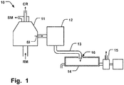
- Fig. 1 is a schematic illustration of how raw milk (RM) enters a centrifuge bowl 11 of a separator 10, and the subsequent separation of the skimmilk phase (SM) and the cream phase (CR) at the top of the centrifuge bowl 11, as well as the ejection of solid impurities in an ejection phase (SI) from the periphery of the centrifuge bowl 11.
- RM raw milk
- the ejection phase (SI) is decelerated in a cyclone 12 and conveyed to a gathering vessel 14 via a pipe 13.
- a pump 15 is connected to the vessel 14 to expel the ejection phase (SI) from the gathering vessel 14.
- Previous separators require considerable maintenance, both in terms of sustaining the intended function over the expected life time, and to satisfy various hygienic requirements. Thus, considerable resources are required for these purposes, as well as factory real estate due to the typically bulky setup of such previous separators.
- examples of the present invention preferably seek to mitigate, alleviate or eliminate one or more deficiencies, disadvantages or issues in the art, such as the above-identified, singly or in any combination by providing a device according to the appended patent claims.
- a separator for separating raw milk into a skimmed milk phase, a cream phase and an ejection phase that comprises solid impurities.
- the separator comprises a centrifuge bowl comprising an inlet for the raw milk and outlets for the skimmed milk phase and the cream phase.
- the centrifuge bowl comprises an ejection port arranged at a periphery of the centrifuge bowl to eject the ejection phase from the centrifuge bowl.
- the separator comprises a cyclone connected to the ejection port to receive and decelerate the ejection phase ejected from the centrifuge bowl, and a vessel in fluid communication with an ejection phase outlet of the cyclone to receive and collect the ejection phase from the cyclone.
- the cyclone comprises a port that is open to the atmosphere, such that pressure build-up created in the cyclone when the ejection phase is ejected from the centrifuge bowl into the cyclone is released.
- a method for separating raw milk into a skimmed milk phase, a cream phase and an ejection phase that comprises solid impurities comprises receiving the raw milk into a centrifuge bowl, ejecting the ejection phase from the centrifuge bowl through an ejection port, receiving and decelerating the ejection phase ejected from the centrifuge bowl in a cyclone connected to the ejection port, and releasing pressure build-up created in the cyclone, when the ejection phase is ejected from the centrifuge bowl into the cyclone, through a port in the cyclone that is open to the atmosphere.
- a cyclone with a port that is open to the atmosphere is advantageous in that it reduces pressure surges, and thereby vibrations, that may be transferred from the cyclone.
- Some examples of the disclosure provide for a more efficient handling of raw milk impurities ejected in a cyclone of a separator.
- Some examples of the disclosure provide for a separator having a smaller foot-print.
- Some examples of the disclosure provide for a more hygienic handling of raw milk impurities ejected in a cyclone of a separator.
- Some examples of the disclosure provide for a more robust separator.
- Some examples of the disclosure provide for a separator requiring less maintenance.
- Some examples of the disclosure provide for increasing the life-time of a separator.
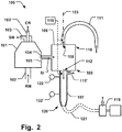
- Fig. 2 is a schematic illustration of a separator 100 for separating raw milk (RM) into a skimmed milk phase (SM), a cream phase (CR) and an ejection phase (SI) that comprises solid impurities (SI).
- the separator 100 comprises a centrifuge bowl 101.
- the centrifuge bowl 101 comprises an inlet 102 for the raw milk (RM), and outlets 103, 103', for the skimmed milk phase (SM) and the cream phase (CR), respectively.
- the centrifuge bowl 101 comprises an ejection port 104 arranged at a periphery 105 of the centrifuge bowl 101.
- the ejection port 104 ejects the ejection phase (SI) from the centrifuge bowl 101.
- the ejection port 104 may be configured to open for a short period of time, and with a predefined frequency so that the impurities collected at the periphery, i.e. at the sediment space, are regularly emptied from the centrifuge bowl 101.
- the separator 100 comprises a cyclone 106 connected to the ejection port 104 to receive and decelerate the ejection phase (SI) ejected from the centrifuge bowl 101.
- the cyclone 106 absorbs the chock of energy of the ejection phase (SI) leaving the centrifuge bowl 101 via the ejection port 104.
- the ejection port 104 may be angled in a tangential direction of the cyclone 106 so that the ejection phase (SI) may be decelerated with a trajectory along the inner curvature of the wall of the cyclone 106, which in principle has the general shape of a cylinder.
- SI ejection phase
- the separator 100 comprises a vessel 107 in fluid communication with an ejection phase outlet 112 of the cyclone 106 to receive and collect the ejection phase (SI) from the cyclone 106.
- the ejection phase (SI) is gathered in the vessel 107 after being decelerated in the cyclone 106.
- the vessel 107 may be in fluid communication with the cyclone 106 by being attached to the cyclone 106 as schematically illustrated in Fig. 2 , or otherwise arranged so that the fluid ejection phase (SI) can flow from the cyclone 106 into the vessel 107, e.g. as illustrated in Fig. 3 where the ejection phase outlet 112 extends into at least part of the vessel 107.
- fluid communication between two parts, such as the cyclone 106 and the vessel 107, means that the parts are arranged such that liquid can flow between the parts.
- the parts may be either directly connected to each other, or may be located adjacent each other with a spacing in between each other, as long as liquid can flow between the parts.
- the cyclone 106 comprises a port 108 that is open to the atmosphere, such that pressure build-up created in the cyclone 106 when the ejection phase (SI) is ejected from the centrifuge bowl 101 into the cyclone 106 is released.
- the port 108 being open to the atmosphere should be construed as the port 108 being in gaseous communication with a surrounding space into which a volume of gas of the cyclone 106 may be released to minimize or lower an momentaneous increase of pressure in the cyclone 106 as the ejection phase (SI) is ejected into the cyclone 106.
- the short burst of impurities ejected into the cyclone 106 creates a pressure pulse in the interior of cyclone 106.
- Having a port 108 in the cyclone 106 that is open to the atmosphere, so that the pressure build-up created by the pulse can escape through the port 108 provides for reducing the pressure fluctuations absorbed by the cyclone 106 itself. Vibrations in the cyclone 106 associated with such fluctuations can thereby be reduced. A reduced amount of vibrations in the cyclone 106 provides for a facilitated handling of the ejection phase (SI) and a more compact separator 100.
- the vessel 14 into which the ejection phase (SI) is conveyed must have a substantial part of its volume sized to absorb the pressure pulse ejected from the cyclone 12, via pipe 12 into the vessel 14.
- the volume of vessel 14 must thus be substantially larger in previous solutions, e.g. twice the volume of the vessel 107 in the presently described separator 100, e.g. 80 liters compared to 40 liters.
- the space saved allows for a more flexible placement of the separator 100, allowing e.g. easier adaptation to different production lines and modifications if needed.
- the fluid ejection phase (SI) may escape through such space 16, due to the turbulence created in the fluid in the vessel 14 from the pressure pulse that is ejected into the vessel 14. This requires more maintenance and is less hygienic.
- a cyclone 106 with a port 108 open to the atmosphere thus provides for absorbing pressure pulses earlier in the separator 100, avoiding the issues from pressure gradients and vibrations downstream in the separator system as encountered in previous solutions.
- a cyclone 106 with a port 108 open to the atmosphere thus provides for a more hygienic handling of raw milk impurities ejected in the cyclone 106, and a more compact separator 100.
- the reduced vibrations also provide for minimizing the risk of mechanical failures and increasing the life time of the separator 100.
- a more robust separator 100 requiring less maintenance is provided.
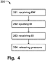
- Fig. 4 illustrates a flow chart of a method 200 for separating raw milk (RM) into a skimmed milk phase (SM), a cream phase (CR) and an ejection phase (SI) that comprises solid impurities (SI).
- the order in which the steps of the method 200 are described and illustrated should not be construed as limiting and it is conceivable that the steps can be performed in varying order.
- the method 200 comprises receiving 201 the raw milk (RM) into a centrifuge bowl 101, and ejecting 202 the ejection phase (SI) from the centrifuge bowl 101 through an ejection port 104.
- the method 200 further comprises receiving 203 and decelerating the ejection phase (SI) ejected from the centrifuge bowl 101 in a cyclone 106 connected to the ejection port 104, and releasing 204 pressure build-up created in the cyclone 106, when the ejection phase (IS) is ejected from the centrifuge bowl 101 into the cyclone 106, through a port 108 in the cyclone 106 that is open to the atmosphere, as described above.
- the method 200 thus provides for the advantageous benefits as described above in relation to the separator 100 and Fig. 2 . I.e.
- the method 200 provides for a more efficient handling of the ejection phase (SI) of raw milk impurities ejected in a cyclone 106 of a separator 100, a more hygienic handling of the ejection phase (SI), less maintenance, and a smaller foot-print of such separator 100.
- SI ejection phase
- SI ejection phase
- the vessel 107 may be arranged at a lower part 109 of the cyclone 106, and the port 108 may be arranged in an opposite, upper part 110 of the cyclone 106.
- the ejection phase (SI) may thus be collected at the lower part 109 without interfering with the gas pressure outlet via the port 108.
- the risk of obstructing the port 108 may thus be minimized and a more robust performance can be ascertained.
- the port 108 may be arranged concentrically in the cyclone 106, i.e. at or adjacent a center axis 123 of the cyclone, as schematically illustrated in Fig. 2 .
- the radial distance between the port 108 and the periphery of the cyclone 106 where the ejection port 104 is connected may thus be maximized. Ejection of the solid impurities in the ejection phase (SI) at the periphery of the cyclone 106 has thus a minimized risk of interfering with the port 108. It is conceivable however that the port 108 may be arranged at other portions of the cyclone 106 while allowing for release of pressure-build up as described.
- the port 108 may be arranged at a side portion of the cyclone 106 while the ejection phase (SI) is prevented from flowing to the port 108 by a shielding structure such as a flange (not shown) at the inside of the cyclone 106.
- a shielding structure such as a flange (not shown) at the inside of the cyclone 106.
- the vessel 107 may be vertically aligned with respect to the cyclone 106, underneath the cyclone 106 so that the ejection phase (SI) can gather in the vessel 107 under the influence of the gravitational force, as schematically illustrated in Figs. 2 and 3 (Fig. 3 shows only a section of the vessel 107).
- This provides for a compact separator 100, since the ejection phase (SI) can flow directly into the vessel 107 from the cyclone 106.
- the absent or minimized vibrations of the cyclone 106 allows accordingly for a facilitated and more flexible positioning of the vessel 107 relative the cyclone 106, due to the alleviated need for vibration accommodating structures or pressure absorbing volume in the vessel itself.
- Figs. 2 - 3 show the vessel 107 concentrically aligned with respect to a center axis 123 of the cyclone 106.
- the vessel 107 may however be arranged at other portions of the cyclone 106 while allowing for the ejection phase (SI) to be collected in the vessel 107 under the influence of the gravitational force, such as off-center to central axis 123.
- SI ejection phase
- the separator 100 may comprise a conduit 111 connected to the port 108, as schematically illustrated in Figs. 2 and 3 .
- the conduit 111 may be deflected from the direction 123 parallel to the center axis 123 of the cyclone 106 (overlapping in the example of Fig. 2 due to the concentric arrangement of the port 108).
- any fluid of the ejection phase (SI) would exit the cyclone 106 via the port 108, it will be deflected via the conduit 111 and collected. This further facilitates a hygienic handling of the ejection phase (SI) in the separator 100.
- the conduit 111 still provides for an opening to the atmosphere for release of the pressure pulses created in the cyclone 106.
- the through-flow area of the ejection phase outlet 112 of the cyclone 106 may be smaller than the through-flow area the port 108. This provides for facilitating the release of the pressure pulse via the port 108, minimizing vibrations of the cyclone 106, while the ejection phase (SI) can flow into the vessel 107 via the ejection phase outlet 112 with a minimal impact from the pressure pulse escaping through the port 108.
- the reduced through-flow area of the ejection phase outlet 112, compared to the through-flow area the port 108, is schematically illustrated in Fig. 2 .
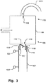
- the through-flow area of the ejection phase outlet 112 has also been reduced in the example of Fig. 3 , via a flow restrictor 113 as described below.
- the through-flow area of the ejection phase outlet 112 of the cyclone 106 may be less than 20% of the through-flow area the port 108. This may provide for a particularly efficient dampening of the pressure pulse as well as sufficient flow rate of the ejection phase (SI) into the vessel 107. It is conceivable however that the ratios between the through-flow areas of the ejection phase outlet 112 and the port 108 may assume other values for optimization to varying conditions and arrangements of the separator 100.
- the through-flow area of the ejection phase outlet 112 of the cyclone 106 may e.g. be less than 10% or less than 5% of the through-flow area the port 108 in some examples.
- the ejection phase outlet 112 may comprise a flow restrictor 113 that is arranged to set a flow of the ejection phase (SI) past the ejection phase outlet 112 to a predefined rate.
- Fig. 3 shows a schematic example of such flow restrictor 113.
- the flow restrictor 113 may have varying shapes and sizes for achieving a desired flow rate of the ejection phase (SI) into the vessel 107. As elucidated above, such optimization allows for attaining efficient dampening of the pressure pulse as well as the necessary flow rate of the ejection phase (SI) into the vessel 107.
- the ejection phase outlet 112 may comprise a flange 114 that extends into at least a part of the vessel 107, as schematically illustrated in the example of Fig. 3 . It may thus be assured that the ejection phase (SI) leaving the cyclone 106 indeed is flowing into the vessel 107, even if there would be a horizontal relative movement between the cyclone 106 and the vessel 107.
- the flange 114 may be an annular structure surrounding the ejection phase outlet 112. It is conceivable that other structures may be arranged at the ejection phase outlet 112, extending into at least part of the vessel 107, that limits a displacement of the vessel 107 and the cyclone 106 relative to each other. A flange 114 may however be particularly advantageous in ensuring that the ejection phase (SI) is transported into the vessel 107 as desired.
- the separator 100 may comprise an overflow passage 115, open to the atmosphere, and arranged between the flange 114 and the vessel 107, thereby allowing the ejection phase (SI) to leave the vessel 107 via the overflow passage 115.
- Fig. 3 schematically illustrates such overflow passage 115, that allows the ejection phase (SI) to be expelled from the vessel 107 in case of a malfunction so that the vessel 107 is not emptied as needed.
- the risk of having the ejection phase (IS) accumulating in the cyclone 106 is thus avoided.
- the latter can be particularly harmful during ejection of the ejection phase (SI) into the cyclone 106.
- the overflow passage 115 thus provides for increasing the safety during operation of the separator 100.
- the overflow passage 115 being open to the atmosphere should be construed as being open to a surrounding space into which the ejection phase (SI) may flow so that a maximum level of ejection phase (SI) fluid in the vessel 107 is not exceeded, i.e. up to the vertical position of the overflow passage 115.
- SI ejection phase
- the overflow passage 115 may be arranged vertically above a lowermost part 117 of the flange 114, as schematically illustrated in Fig. 3 .
- An uppermost part 116 or the vessel 107 is located vertically above a lowermost part 117 of the flange 114.
- the risk of having the ejection phase (SI) flowing out from the overflow passage 115 when the vessel 107 is in not filled to the vertical position of the overflow passage 115 may thus be minimized. I.e. a flow directly from the ejection phase outlet 112 to the overflow passage 115 is prevented. This further facilitates the hygienic handling of the ejection phase (SI) in the separator 100.
- the cyclone 106 and the flange 114 at the ejection phase outlet 112 may be freely moveable relative the vessel 107.
- the flange 114 and vessel 107 may be dimensioned to provide a space between the flange 114 and the vessel 107 that allows for relative movement therebetween, as well as space for the overflow passage 115 mentioned above. Any vibrations may thus be accommodated in the mentioned space, which further minimizes the risk of any undesired oscillations downstream the cyclone 106.
- An overflow passage 115' of the vessel 107 is also illustrated in the example of Fig. 2 .
- the overflow passage 115' may comprise an opening in the vessel 107 adjacent and below the ejection phase outlet 112 in the vertical direction.
- the separator 100 may comprise a cleaning unit 118 arranged adjacent the port 180 and the ejection phase outlet 112, as schematically illustrated in Fig. 2 .
- the cleaning unit 118 may comprise a first and second cleaning device, such as a CIP (cleaning in place device).
- the CIP device may comprise a rotating device configured to eject a cleaning fluid e.g. water around its vicinity.
- the first and/or second cleaning device may be arranged less than 20 cm from the port 180 and/or the ejection phase outlet 112, to provide for a particularly efficient cleaning operation.
- the cleaning device may be used for the embodiment shown in Fig. 3 .
- the separator 100 may comprise a pump 119 connected to the vessel 107 at a lower part 120 thereof for expelling the ejection phase (SI) from the vessel 107, as schematically illustrated in Fig. 2 .
- the pump 119 may be connected to the vessel 107 via a flexible conduit 121. Any vibrations may thus be further effectively damped and absorbed by the flexible conduit 121 in case the vessel 107 is directly attached to the cyclone 106.
- the embodiment of Fig. 3 can reduce or even eliminate vibrations from the cyclone 106 to the vessel 107. Still, the flexible conduit may be used also for the Fig. 3 embodiment.
- the vessel 107 may comprise a sensor 122, 122', arranged to detect a level of ejection phase (SI) in the vessel 107 to trigger expulsion of the ejection phase (SI) from the vessel 107 via a pump 119 connected to the vessel 107.
- Figs. 1 - 2 schematically illustrate such sensor 122, 122', being arranged at a lower and upper level of the vessel 107.
- the pump 119 may be triggered for expulsion of the ejection phase (SI) from the vessel when reaching the upper sensor 122 in the vertical direction of the vessel.
- An efficient and safe operation of the separating unit 100 may thus be further ensured.
Landscapes
- Life Sciences & Earth Sciences (AREA)
- Chemical & Material Sciences (AREA)
- Engineering & Computer Science (AREA)
- Food Science & Technology (AREA)
- Polymers & Plastics (AREA)
- Animal Husbandry (AREA)
- Environmental Sciences (AREA)
- Cyclones (AREA)
Abstract
Description
- The present invention relates to a separator for separating raw milk into a skimmed milk phase, a cream phase and an ejection phase that comprises solid impurities, and a related method.
- Separators for separating raw milk into different phases of varying density under the influence of a centrifugal force are called centrifugal separators. The raw milk is introduced in a rotating disc stack of the centrifugal separator. Under the influence of the centrifugal force heavier sediment and lighter fat globules in the raw milk begin to settle radially outwards respectively inwards in the separation channels according to their density relative to that of skimmilk. The high-density solid impurities in the milk will settle outwards towards the periphery of the separator and collect in a sediment space. The solids that collect in the sediment space may comprise straw and hairs, udder cells, white blood corpuscles (leucocytes), red blood corpuscles, bacteria, etc. The cream, i.e. the fat globules, has a lower density than the skimmilk and therefore moves inwards in the channels, towards the separator's axis of rotation. The cream continues to an axial outlet and the skimmilk moves outwards to the space outside the disc stack and from there to a skimmilk outlet.
Fig. 1 is a schematic illustration of how raw milk (RM) enters acentrifuge bowl 11 of aseparator 10, and the subsequent separation of the skimmilk phase (SM) and the cream phase (CR) at the top of thecentrifuge bowl 11, as well as the ejection of solid impurities in an ejection phase (SI) from the periphery of thecentrifuge bowl 11. The ejection phase (SI) is decelerated in acyclone 12 and conveyed to agathering vessel 14 via apipe 13. Apump 15 is connected to thevessel 14 to expel the ejection phase (SI) from thegathering vessel 14. Previous separators require considerable maintenance, both in terms of sustaining the intended function over the expected life time, and to satisfy various hygienic requirements. Thus, considerable resources are required for these purposes, as well as factory real estate due to the typically bulky setup of such previous separators. - It would thus be advantageous with an improved separator, in particular allowing for avoiding at least some of the above-mentioned problems and compromises, including providing for a more efficient handling of the ejection phase of raw milk impurities ejected in a cyclone of the separator. Additionally, more hygienic handling of the ejection phase, less maintenance, and a smaller foot-print of such separator would be desired.
- Accordingly, examples of the present invention preferably seek to mitigate, alleviate or eliminate one or more deficiencies, disadvantages or issues in the art, such as the above-identified, singly or in any combination by providing a device according to the appended patent claims.
- According to a first aspect a separator for separating raw milk into a skimmed milk phase, a cream phase and an ejection phase that comprises solid impurities is provided. The separator comprises a centrifuge bowl comprising an inlet for the raw milk and outlets for the skimmed milk phase and the cream phase. The centrifuge bowl comprises an ejection port arranged at a periphery of the centrifuge bowl to eject the ejection phase from the centrifuge bowl. The separator comprises a cyclone connected to the ejection port to receive and decelerate the ejection phase ejected from the centrifuge bowl, and a vessel in fluid communication with an ejection phase outlet of the cyclone to receive and collect the ejection phase from the cyclone. The cyclone comprises a port that is open to the atmosphere, such that pressure build-up created in the cyclone when the ejection phase is ejected from the centrifuge bowl into the cyclone is released.
- According to a second aspect a method for separating raw milk into a skimmed milk phase, a cream phase and an ejection phase that comprises solid impurities is provided. The method comprises receiving the raw milk into a centrifuge bowl, ejecting the ejection phase from the centrifuge bowl through an ejection port, receiving and decelerating the ejection phase ejected from the centrifuge bowl in a cyclone connected to the ejection port, and releasing pressure build-up created in the cyclone, when the ejection phase is ejected from the centrifuge bowl into the cyclone, through a port in the cyclone that is open to the atmosphere.
- Further examples of the invention are defined in the dependent claims, wherein features for the first aspect may be implemented for the second aspect, and vice versa.
- Using a cyclone with a port that is open to the atmosphere is advantageous in that it reduces pressure surges, and thereby vibrations, that may be transferred from the cyclone.
- Some examples of the disclosure provide for a more efficient handling of raw milk impurities ejected in a cyclone of a separator.
- Some examples of the disclosure provide for a separator having a smaller foot-print.
- Some examples of the disclosure provide for a more hygienic handling of raw milk impurities ejected in a cyclone of a separator.
- Some examples of the disclosure provide for a more robust separator.
- Some examples of the disclosure provide for a separator requiring less maintenance.
- Some examples of the disclosure provide for increasing the life-time of a separator.
- These and other aspects, features and advantages of which examples of the invention are capable of will be apparent and elucidated from the following description of examples of the present invention, reference being made to the accompanying drawings, in which;
-
Fig. 1 is a schematic illustration of a separator for separating raw milk into a skimmed milk phase, a cream phase and an ejection phase (SI), according to the prior art; -
Fig. 2 is a schematic illustration of a separator comprising a centrifuge bowl, a cyclone, and a vessel, according to examples of the disclosure; -
Fig. 3 is a schematic illustration of a cyclone of a separator, according to examples of the disclosure; and -
Fig. 4 is a flowchart of a method for separating raw milk into a skimmed milk phase, a cream phase and an ejection phase, according to examples of the disclosure. - Specific examples of the invention will now be described with reference to the accompanying drawings. This invention may, however, be embodied in many different forms and should not be construed as limited to the examples set forth herein; rather, these examples are provided so that this disclosure will be thorough and complete, and will fully convey the scope of the invention to those skilled in the art. The terminology used in the detailed description of the examples illustrated in the accompanying drawings is not intended to be limiting of the invention. In the drawings, like numbers refer to like elements.
-
Fig. 2 is a schematic illustration of aseparator 100 for separating raw milk (RM) into a skimmed milk phase (SM), a cream phase (CR) and an ejection phase (SI) that comprises solid impurities (SI). Theseparator 100 comprises acentrifuge bowl 101. Thecentrifuge bowl 101 comprises aninlet 102 for the raw milk (RM), andoutlets 103, 103', for the skimmed milk phase (SM) and the cream phase (CR), respectively. Thecentrifuge bowl 101 comprises anejection port 104 arranged at aperiphery 105 of thecentrifuge bowl 101. Theejection port 104 ejects the ejection phase (SI) from thecentrifuge bowl 101. Theejection port 104 may be configured to open for a short period of time, and with a predefined frequency so that the impurities collected at the periphery, i.e. at the sediment space, are regularly emptied from thecentrifuge bowl 101. Theseparator 100 comprises acyclone 106 connected to theejection port 104 to receive and decelerate the ejection phase (SI) ejected from thecentrifuge bowl 101. Thus, thecyclone 106 absorbs the chock of energy of the ejection phase (SI) leaving thecentrifuge bowl 101 via theejection port 104. Theejection port 104 may be angled in a tangential direction of thecyclone 106 so that the ejection phase (SI) may be decelerated with a trajectory along the inner curvature of the wall of thecyclone 106, which in principle has the general shape of a cylinder. - The
separator 100 comprises avessel 107 in fluid communication with anejection phase outlet 112 of thecyclone 106 to receive and collect the ejection phase (SI) from thecyclone 106. Hence, the ejection phase (SI) is gathered in thevessel 107 after being decelerated in thecyclone 106. Thevessel 107 may be in fluid communication with thecyclone 106 by being attached to thecyclone 106 as schematically illustrated inFig. 2 , or otherwise arranged so that the fluid ejection phase (SI) can flow from thecyclone 106 into thevessel 107, e.g. as illustrated inFig. 3 where theejection phase outlet 112 extends into at least part of thevessel 107. - Herein, "fluid communication" between two parts, such as the
cyclone 106 and thevessel 107, means that the parts are arranged such that liquid can flow between the parts. The parts may be either directly connected to each other, or may be located adjacent each other with a spacing in between each other, as long as liquid can flow between the parts. - The
cyclone 106 comprises aport 108 that is open to the atmosphere, such that pressure build-up created in thecyclone 106 when the ejection phase (SI) is ejected from thecentrifuge bowl 101 into thecyclone 106 is released. Theport 108 being open to the atmosphere should be construed as theport 108 being in gaseous communication with a surrounding space into which a volume of gas of thecyclone 106 may be released to minimize or lower an momentaneous increase of pressure in thecyclone 106 as the ejection phase (SI) is ejected into thecyclone 106. The short burst of impurities ejected into thecyclone 106 creates a pressure pulse in the interior ofcyclone 106. Having aport 108 in thecyclone 106 that is open to the atmosphere, so that the pressure build-up created by the pulse can escape through theport 108 provides for reducing the pressure fluctuations absorbed by thecyclone 106 itself. Vibrations in thecyclone 106 associated with such fluctuations can thereby be reduced. A reduced amount of vibrations in thecyclone 106 provides for a facilitated handling of the ejection phase (SI) and a morecompact separator 100. For example, in priorart separator systems 10, as illustrated inFig. 1 , thevessel 14 into which the ejection phase (SI) is conveyed must have a substantial part of its volume sized to absorb the pressure pulse ejected from thecyclone 12, viapipe 12 into thevessel 14. The volume ofvessel 14 must thus be substantially larger in previous solutions, e.g. twice the volume of thevessel 107 in the presently describedseparator 100, e.g. 80 liters compared to 40 liters. The space saved allows for a more flexible placement of theseparator 100, allowing e.g. easier adaptation to different production lines and modifications if needed. Furthermore, due to the significant vibrations in thecyclone 12 of previous solutions and components connected thereto such as theconveyor pipe 13, it is necessary to have aspace 16 at the opening of thevessel 14 where thepipe 13 can oscillate due to such vibrations. The fluid ejection phase (SI) may escape throughsuch space 16, due to the turbulence created in the fluid in thevessel 14 from the pressure pulse that is ejected into thevessel 14. This requires more maintenance and is less hygienic. - Having a
cyclone 106 with aport 108 open to the atmosphere as described above thus provides for absorbing pressure pulses earlier in theseparator 100, avoiding the issues from pressure gradients and vibrations downstream in the separator system as encountered in previous solutions. Acyclone 106 with aport 108 open to the atmosphere thus provides for a more hygienic handling of raw milk impurities ejected in thecyclone 106, and a morecompact separator 100. The reduced vibrations also provide for minimizing the risk of mechanical failures and increasing the life time of theseparator 100. A morerobust separator 100 requiring less maintenance is provided. -
Fig. 4 illustrates a flow chart of amethod 200 for separating raw milk (RM) into a skimmed milk phase (SM), a cream phase (CR) and an ejection phase (SI) that comprises solid impurities (SI). The order in which the steps of themethod 200 are described and illustrated should not be construed as limiting and it is conceivable that the steps can be performed in varying order. Themethod 200 comprises receiving 201 the raw milk (RM) into acentrifuge bowl 101, and ejecting 202 the ejection phase (SI) from thecentrifuge bowl 101 through anejection port 104. Themethod 200 further comprises receiving 203 and decelerating the ejection phase (SI) ejected from thecentrifuge bowl 101 in acyclone 106 connected to theejection port 104, and releasing 204 pressure build-up created in thecyclone 106, when the ejection phase (IS) is ejected from thecentrifuge bowl 101 into thecyclone 106, through aport 108 in thecyclone 106 that is open to the atmosphere, as described above. Themethod 200 thus provides for the advantageous benefits as described above in relation to theseparator 100 andFig. 2 . I.e. themethod 200 provides for a more efficient handling of the ejection phase (SI) of raw milk impurities ejected in acyclone 106 of aseparator 100, a more hygienic handling of the ejection phase (SI), less maintenance, and a smaller foot-print ofsuch separator 100. - Returning to the examples of
Figs. 2 and3 , thevessel 107 may be arranged at alower part 109 of thecyclone 106, and theport 108 may be arranged in an opposite,upper part 110 of thecyclone 106. The ejection phase (SI) may thus be collected at thelower part 109 without interfering with the gas pressure outlet via theport 108. The risk of obstructing theport 108 may thus be minimized and a more robust performance can be ascertained. Theport 108 may be arranged concentrically in thecyclone 106, i.e. at or adjacent acenter axis 123 of the cyclone, as schematically illustrated inFig. 2 . The radial distance between theport 108 and the periphery of thecyclone 106 where theejection port 104 is connected may thus be maximized. Ejection of the solid impurities in the ejection phase (SI) at the periphery of thecyclone 106 has thus a minimized risk of interfering with theport 108. It is conceivable however that theport 108 may be arranged at other portions of thecyclone 106 while allowing for release of pressure-build up as described. For example, theport 108 may be arranged at a side portion of thecyclone 106 while the ejection phase (SI) is prevented from flowing to theport 108 by a shielding structure such as a flange (not shown) at the inside of thecyclone 106. - The
vessel 107 may be vertically aligned with respect to thecyclone 106, underneath thecyclone 106 so that the ejection phase (SI) can gather in thevessel 107 under the influence of the gravitational force, as schematically illustrated inFigs. 2 and3 (Fig. 3 shows only a section of the vessel 107). This provides for acompact separator 100, since the ejection phase (SI) can flow directly into thevessel 107 from thecyclone 106. The absent or minimized vibrations of thecyclone 106 allows accordingly for a facilitated and more flexible positioning of thevessel 107 relative thecyclone 106, due to the alleviated need for vibration accommodating structures or pressure absorbing volume in the vessel itself. The reduced foot-print of theseparator 100 provides for easy and resource efficient integration in a production line.Figs. 2 - 3 show thevessel 107 concentrically aligned with respect to acenter axis 123 of thecyclone 106. Thevessel 107 may however be arranged at other portions of thecyclone 106 while allowing for the ejection phase (SI) to be collected in thevessel 107 under the influence of the gravitational force, such as off-center tocentral axis 123. - The
separator 100 may comprise aconduit 111 connected to theport 108, as schematically illustrated inFigs. 2 and3 . Theconduit 111 may be deflected from thedirection 123 parallel to thecenter axis 123 of the cyclone 106 (overlapping in the example ofFig. 2 due to the concentric arrangement of the port 108). In case any fluid of the ejection phase (SI) would exit thecyclone 106 via theport 108, it will be deflected via theconduit 111 and collected. This further facilitates a hygienic handling of the ejection phase (SI) in theseparator 100. Theconduit 111 still provides for an opening to the atmosphere for release of the pressure pulses created in thecyclone 106. - The through-flow area of the
ejection phase outlet 112 of thecyclone 106 may be smaller than the through-flow area theport 108. This provides for facilitating the release of the pressure pulse via theport 108, minimizing vibrations of thecyclone 106, while the ejection phase (SI) can flow into thevessel 107 via theejection phase outlet 112 with a minimal impact from the pressure pulse escaping through theport 108. The reduced through-flow area of theejection phase outlet 112, compared to the through-flow area theport 108, is schematically illustrated inFig. 2 . The through-flow area of theejection phase outlet 112 has also been reduced in the example ofFig. 3 , via aflow restrictor 113 as described below. - In one example, the through-flow area of the
ejection phase outlet 112 of thecyclone 106 may be less than 20% of the through-flow area theport 108. This may provide for a particularly efficient dampening of the pressure pulse as well as sufficient flow rate of the ejection phase (SI) into thevessel 107. It is conceivable however that the ratios between the through-flow areas of theejection phase outlet 112 and theport 108 may assume other values for optimization to varying conditions and arrangements of theseparator 100. The through-flow area of theejection phase outlet 112 of thecyclone 106 may e.g. be less than 10% or less than 5% of the through-flow area theport 108 in some examples. - The
ejection phase outlet 112 may comprise aflow restrictor 113 that is arranged to set a flow of the ejection phase (SI) past theejection phase outlet 112 to a predefined rate.Fig. 3 shows a schematic example ofsuch flow restrictor 113. The flow restrictor 113 may have varying shapes and sizes for achieving a desired flow rate of the ejection phase (SI) into thevessel 107. As elucidated above, such optimization allows for attaining efficient dampening of the pressure pulse as well as the necessary flow rate of the ejection phase (SI) into thevessel 107. - The
ejection phase outlet 112 may comprise aflange 114 that extends into at least a part of thevessel 107, as schematically illustrated in the example ofFig. 3 . It may thus be assured that the ejection phase (SI) leaving thecyclone 106 indeed is flowing into thevessel 107, even if there would be a horizontal relative movement between thecyclone 106 and thevessel 107. Theflange 114 may be an annular structure surrounding theejection phase outlet 112. It is conceivable that other structures may be arranged at theejection phase outlet 112, extending into at least part of thevessel 107, that limits a displacement of thevessel 107 and thecyclone 106 relative to each other. Aflange 114 may however be particularly advantageous in ensuring that the ejection phase (SI) is transported into thevessel 107 as desired. - The
separator 100 may comprise anoverflow passage 115, open to the atmosphere, and arranged between theflange 114 and thevessel 107, thereby allowing the ejection phase (SI) to leave thevessel 107 via theoverflow passage 115.Fig. 3 schematically illustratessuch overflow passage 115, that allows the ejection phase (SI) to be expelled from thevessel 107 in case of a malfunction so that thevessel 107 is not emptied as needed. The risk of having the ejection phase (IS) accumulating in thecyclone 106 is thus avoided. The latter can be particularly harmful during ejection of the ejection phase (SI) into thecyclone 106. Theoverflow passage 115 thus provides for increasing the safety during operation of theseparator 100. Theoverflow passage 115 being open to the atmosphere should be construed as being open to a surrounding space into which the ejection phase (SI) may flow so that a maximum level of ejection phase (SI) fluid in thevessel 107 is not exceeded, i.e. up to the vertical position of theoverflow passage 115. - The
overflow passage 115 may be arranged vertically above alowermost part 117 of theflange 114, as schematically illustrated inFig. 3 . Anuppermost part 116 or thevessel 107 is located vertically above alowermost part 117 of theflange 114. The risk of having the ejection phase (SI) flowing out from theoverflow passage 115 when thevessel 107 is in not filled to the vertical position of theoverflow passage 115 may thus be minimized. I.e. a flow directly from theejection phase outlet 112 to theoverflow passage 115 is prevented. This further facilitates the hygienic handling of the ejection phase (SI) in theseparator 100. - The
cyclone 106 and theflange 114 at theejection phase outlet 112 may be freely moveable relative thevessel 107. Hence, theflange 114 andvessel 107 may be dimensioned to provide a space between theflange 114 and thevessel 107 that allows for relative movement therebetween, as well as space for theoverflow passage 115 mentioned above. Any vibrations may thus be accommodated in the mentioned space, which further minimizes the risk of any undesired oscillations downstream thecyclone 106. - An overflow passage 115' of the
vessel 107 is also illustrated in the example ofFig. 2 . In this case, when thevessel 107 is connected to thecyclone 106, the overflow passage 115' may comprise an opening in thevessel 107 adjacent and below theejection phase outlet 112 in the vertical direction. - The
separator 100 may comprise acleaning unit 118 arranged adjacent the port 180 and theejection phase outlet 112, as schematically illustrated inFig. 2 . This allows for efficient cleaning of theseparator 100 and minimized risk of accumulation of unwanted contaminants. Thecleaning unit 118 may comprise a first and second cleaning device, such as a CIP (cleaning in place device). The CIP device may comprise a rotating device configured to eject a cleaning fluid e.g. water around its vicinity. The first and/or second cleaning device may be arranged less than 20 cm from the port 180 and/or theejection phase outlet 112, to provide for a particularly efficient cleaning operation. The cleaning device may be used for the embodiment shown inFig. 3 . - The
separator 100 may comprise apump 119 connected to thevessel 107 at alower part 120 thereof for expelling the ejection phase (SI) from thevessel 107, as schematically illustrated inFig. 2 . Thepump 119 may be connected to thevessel 107 via aflexible conduit 121. Any vibrations may thus be further effectively damped and absorbed by theflexible conduit 121 in case thevessel 107 is directly attached to thecyclone 106. The embodiment ofFig. 3 can reduce or even eliminate vibrations from thecyclone 106 to thevessel 107. Still, the flexible conduit may be used also for theFig. 3 embodiment. - The
vessel 107 may comprise asensor 122, 122', arranged to detect a level of ejection phase (SI) in thevessel 107 to trigger expulsion of the ejection phase (SI) from thevessel 107 via apump 119 connected to thevessel 107.Figs. 1 - 2 schematically illustratesuch sensor 122, 122', being arranged at a lower and upper level of thevessel 107. Hence, thepump 119 may be triggered for expulsion of the ejection phase (SI) from the vessel when reaching theupper sensor 122 in the vertical direction of the vessel. An efficient and safe operation of theseparating unit 100 may thus be further ensured. - The present invention has been described above with reference to specific examples. However, other examples than the above described are equally possible within the scope of the invention. The different features and steps of the invention may be combined in other combinations than those described. The scope of the invention is only limited by the appended patent claims.
Claims (15)
- A separator (100) for separating raw milk (RM) into a skimmed milk phase (SM), a cream phase (CR) and an ejection phase (SI) that comprises solid impurities (SI), the separator (100) comprises
a centrifuge bowl (101) comprisingan inlet (102) for the raw milk (RM) and outlets (103, 103') for the skimmed milk phase (SM) and the cream phase (CR),an ejection port (104) arranged at a periphery (105) of the centrifuge bowl (101) to eject the ejection phase (SI) from the centrifuge bowl (101),a cyclone (106) connected to the ejection port (104) to receive and decelerate the ejection phase (SI) ejected from the centrifuge bowl (101),
a vessel (107) in fluid communication with an ejection phase outlet (112) of the cyclone (106) to receive and collect the ejection phase (SI) from the cyclone (106), wherein
the cyclone (106) comprises a port (108) that is open to the atmosphere, for releasing pressure build-up created in the cyclone (106) when the ejection phase (SI) is ejected from the centrifuge bowl (101) into the cyclone (106). - The separator according to claim 1, wherein the vessel (107) is arranged at a lower part (109) of the cyclone (106), and the port (108) is arranged in an opposite, upper part (110) of the cyclone (106).
- The separator according to claim 1 or 2, comprising a conduit (111) connected to the port (108), wherein the conduit (111) is deflected from a direction that is parallel to the center axis (123) of the cyclone (106).
- The separator according to any of claims 1 - 3, wherein the through-flow area of the ejection phase outlet (112) of the cyclone (106) is smaller than the through-flow area the port (108).
- The separator according to claim 4, wherein the through-flow area of the ejection phase outlet (112) of the cyclone (106) is less than 20% of the through-flow area the port (108).
- The separator according to claim 4 or 5, wherein the ejection phase outlet (112) comprises a flow restrictor (113) that is arranged to set a flow of the ejection phase (SI) past the ejection phase outlet (112) to a predefined rate.
- The separator according to any of claims 1 - 6, wherein the vessel (107) is vertically aligned with respect to the cyclone (106), underneath the cyclone (106) so that the ejection phase (SI) can gather in the vessel (107) under the influence of the gravitational force.
- The separator according to any of claims 1 - 7, wherein the ejection phase outlet (112) comprises a flange (114) that extends into at least a part of the vessel (107).
- The separator according to claim 8, wherein an overflow passage (115) that is open to the atmosphere is arranged between the flange (114) and the vessel (107), such that the overflow passage (115) allows ejection phase (SI) to leave the vessel (107) via the overflow passage (115).
- The separator according to claim 9, wherein the overflow passage (115) is arranged vertically above a lowermost part (117) of the flange (114).
- The separator according to claim 9 or 10, wherein the cyclone (106) and the flange (114) at the ejection phase outlet (112) are freely moveable relative the vessel (107).
- The separator according to any of claims 1 - 11, comprising a cleaning unit (118) arranged adjacent the port (180) and the ejection phase outlet (112).
- The separator according to any of claims 1 - 12, comprising a pump (119) connected to the vessel (107) at a lower part (120) thereof for expelling the ejection phase (SI) from the vessel (107), wherein the pump (119) is connected to the vessel (107) via a flexible conduit (121).
- The separator according to any of claims 1 - 13, wherein the vessel (107) comprises a sensor (122, 122') arranged to detect a level of ejection phase (SI) in the vessel (107) to trigger expulsion of the ejection phase (SI) from the vessel (107) via a pump (119) connected to the vessel (107).
- A method (200) for separating raw milk (RM) into a skimmed milk phase (SM), a cream phase (CR) and an ejection phase (SI) that comprises solid impurities (SI), the method (200) comprises
receiving (201) the raw milk (RM) into a centrifuge bowl (101),
ejecting (202) the ejection phase (SI) from the centrifuge bowl (101) through an ejection port (104),
receiving (203) and decelerating the ejection phase (SI) ejected from the centrifuge bowl (101) in a cyclone (106) connected to the ejection port (104), and
releasing (204) pressure build-up created in the cyclone (106), when the ejection phase (IS) is ejected from the centrifuge bowl (101) into the cyclone (106), through a port (108) in the cyclone (106) that is open to the atmosphere.
Applications Claiming Priority (1)
| Application Number | Priority Date | Filing Date | Title |
|---|---|---|---|
| EP17208512 | 2017-12-19 |
Publications (2)
| Publication Number | Publication Date |
|---|---|
| EP3501661A1 true EP3501661A1 (en) | 2019-06-26 |
| EP3501661B1 EP3501661B1 (en) | 2021-07-21 |
Family
ID=60674009
Family Applications (1)
| Application Number | Title | Priority Date | Filing Date |
|---|---|---|---|
| EP18204511.2A Active EP3501661B1 (en) | 2017-12-19 | 2018-11-06 | A separator and a method for separating milk |
Country Status (4)
| Country | Link |
|---|---|
| US (1) | US12022795B2 (en) |
| EP (1) | EP3501661B1 (en) |
| CN (1) | CN111511474B (en) |
| WO (1) | WO2019120730A1 (en) |
Families Citing this family (2)
| Publication number | Priority date | Publication date | Assignee | Title |
|---|---|---|---|---|
| CN112718271B (en) * | 2020-12-16 | 2022-08-12 | 中国科学院合肥物质科学研究院 | Gravity Vortex Filter Unit |
| EP4568790A1 (en) * | 2022-08-10 | 2025-06-18 | GEA Westfalia Separator Group GmbH | Separating apparatus for separating a suspension |
Citations (2)
| Publication number | Priority date | Publication date | Assignee | Title |
|---|---|---|---|---|
| GB2106368A (en) * | 1981-09-22 | 1983-04-13 | Alfa Laval Ab | Process and apparatus for sterilising microbe-containing liquid |
| WO2005086994A1 (en) * | 2004-03-15 | 2005-09-22 | Tetra Laval Holdings & Finance Sa | A method of improving the efficiency of fat separation in the separation of a liquid food product |
Family Cites Families (38)
| Publication number | Priority date | Publication date | Assignee | Title |
|---|---|---|---|---|
| US2756878A (en) * | 1952-06-10 | 1956-07-31 | Erie Mining Co | Three product wet cyclone |
| BE531264A (en) * | 1953-08-26 | 1900-01-01 | ||
| GB987474A (en) * | 1962-07-03 | 1965-03-31 | Burnett & Rolfe Ltd | Improvements relating to film evaporators |
| FR90904E (en) * | 1965-07-29 | 1968-03-08 | Grenobloise Etude Appl | Hydrocyclone improvements |
| DE2517938C2 (en) * | 1975-04-23 | 1977-06-08 | Westfalia Separator Ag | DEVICE FOR THE CONTINUOUS PRODUCTION OF STANDARDIZED MILK |
| DK139742B (en) * | 1975-06-18 | 1979-04-09 | Niro Atomizer As | Centrifugal separator for separating liquid and gas. |
| US4405265A (en) * | 1981-03-18 | 1983-09-20 | Beloit Corporation | Method and apparatus for the continuous transfer of particulates from a liquid conveying medium to a gaseous conveying medium |
| US4464264A (en) * | 1982-03-04 | 1984-08-07 | Noel Carroll | Cyclone separator |
| JPS62129164A (en) * | 1985-11-28 | 1987-06-11 | Mitsui Toatsu Chem Inc | Method for separating polymer powder and carrier gas |
| DE3802305C1 (en) * | 1988-01-27 | 1989-10-05 | Westfalia Separator Ag, 4740 Oelde, De | Process and apparatus for the centrifugal removal of bacteria from milk |
| SE467392B (en) * | 1989-08-03 | 1992-07-13 | Richard Berg Ab | DEVICE FOR Separation of sand and other heavier particles from a liquid |
| DE4139380C2 (en) * | 1991-11-29 | 1994-08-04 | Westfalia Separator Ag | Process and installation for regulating the fat content of milk |
| FR2691382B1 (en) * | 1992-05-22 | 1994-09-09 | Cit Alcatel | Pumping installation for pumping an enclosure containing gases mixed with solid particles or liable to generate solid particles or condensates. |
| AU692605B2 (en) * | 1994-09-30 | 1998-06-11 | John Bell Mckeown | Separation device |
| GB9819525D0 (en) * | 1998-09-09 | 1998-10-28 | Elopak Systems | Method and apparatus |
| CA2298968A1 (en) * | 1999-02-22 | 2000-08-22 | Jeremy Brett Bosman | Hydrocyclone with removal of misplaced coarse fraction in overflow |
| US8578628B2 (en) * | 2000-08-29 | 2013-11-12 | Rich Technology Solutions Limited | Milling and drying apparatus incorporating a cyclone |
| CN2506957Y (en) * | 2001-10-29 | 2002-08-21 | 南京彤天科技实业有限责任公司 | High speed centrifugal spraying dryer with circular air blowing |
| US6833016B2 (en) * | 2003-03-27 | 2004-12-21 | Oneida Air Systems, Inc | Dust collection system |
| DE102004038474B3 (en) * | 2003-10-24 | 2005-12-29 | Fritz Sperber Gmbh & Co. | Turbine-driven mobile vacuum sweeper for e.g. public open space has a cyclone dust separator discharging to a secondary hopper |
| DE10361520C5 (en) | 2003-12-23 | 2012-02-23 | Gea Westfalia Separator Gmbh | Method for preventing clogging of the flow paths of a separator |
| DE102004035223A1 (en) | 2004-07-21 | 2006-02-16 | Westfalia Separator Ag | Separator and process for degerming raw milk or whey |
| CN101267891A (en) * | 2005-08-12 | 2008-09-17 | 伟尔矿物澳大利亚私人有限公司 | Hydrocyclone Related Improvements |
| US8403149B2 (en) * | 2005-11-18 | 2013-03-26 | Ricoh Company, Ltd. | Cyclone classifier, flash drying system using the cyclone classifier, and toner prepared by the flash drying system |
| US7282074B1 (en) * | 2006-04-28 | 2007-10-16 | Witter Robert M | Auxiliary dust collection system |
| WO2008042444A2 (en) * | 2006-10-07 | 2008-04-10 | Tbw Industries | Vacuum line clean-out separator system |
| SE531211C2 (en) * | 2007-06-21 | 2009-01-20 | Tetra Laval Holdings & Finance | Method of streamlining fat separation by separating a liquid food product |
| US10040077B1 (en) * | 2015-05-19 | 2018-08-07 | Pneumatic Scale Corporation | Centrifuge system including a control circuit that controls positive back pressure within the centrifuge core |
| US9222067B2 (en) * | 2008-04-22 | 2015-12-29 | Pneumatic Scale Corporation | Single use centrifuge system for highly concentrated and/or turbid feeds |
| US8393050B2 (en) * | 2009-10-28 | 2013-03-12 | Robert M. Witter | Portable cyclonic dust collector/vacuum cleaner |
| JP4621802B1 (en) * | 2010-02-09 | 2011-01-26 | 株式会社ワールドケミカル | Self-priming solid-liquid separator |
| CN103917089B (en) * | 2011-11-07 | 2016-02-24 | 利乐拉瓦尔集团及财务有限公司 | For the production of method and the equipment thereof of skimmed milk raw milk |
| US9169088B2 (en) * | 2012-09-20 | 2015-10-27 | Nordson Corporation | Adhesive dispensing device having optimized cyclonic separator unit |
| KR101358338B1 (en) * | 2013-08-19 | 2014-02-11 | 제이에스이엔지(주) | Apparatus for separating iron from liquid compound |
| WO2015095886A1 (en) * | 2013-12-20 | 2015-06-25 | Onesubsea Ip Uk Limited | Systems and methods for subsea fluid phase separation |
| DE102014019014B4 (en) * | 2014-12-18 | 2020-09-17 | Gea Tds Gmbh | Method and installation for the treatment of milk for the production of cheese milk with a reduced content of germs and bacteria |
| CN106179785B (en) * | 2016-08-29 | 2019-06-21 | 云南磷化集团有限公司 | One liter of one drop of overflow fineness appreciation drops cyclone bar shaped unit integrated technology without equal |
| US10905998B2 (en) * | 2017-07-20 | 2021-02-02 | Brett Evan Patrick | Process and apparatus to remove carbon-14 from carbon-dioxide in atmospheric gases and agricultural products grown in controlled environments |
-
2018
- 2018-11-06 CN CN201880082410.1A patent/CN111511474B/en active Active
- 2018-11-06 WO PCT/EP2018/080233 patent/WO2019120730A1/en not_active Ceased
- 2018-11-06 EP EP18204511.2A patent/EP3501661B1/en active Active
- 2018-11-06 US US16/954,677 patent/US12022795B2/en active Active
Patent Citations (2)
| Publication number | Priority date | Publication date | Assignee | Title |
|---|---|---|---|---|
| GB2106368A (en) * | 1981-09-22 | 1983-04-13 | Alfa Laval Ab | Process and apparatus for sterilising microbe-containing liquid |
| WO2005086994A1 (en) * | 2004-03-15 | 2005-09-22 | Tetra Laval Holdings & Finance Sa | A method of improving the efficiency of fat separation in the separation of a liquid food product |
Non-Patent Citations (1)
| Title |
|---|
| KIRSCHENMANN B: "BACTOFUGATION, BACTOFUGAT UND BACTOFUGENSCHLAMM", DMZ. LEBENSMITTELINDUSTRIE UND MILCHWISSENSCHAFT, VOLKSWIRTSCHAFTLICHER VERLAG GMBH. MUNCHEN, DE, vol. 110, no. 21, 24 May 1989 (1989-05-24), pages 654,657, XP000007945, ISSN: 0938-9369 * |
Also Published As
| Publication number | Publication date |
|---|---|
| US12022795B2 (en) | 2024-07-02 |
| WO2019120730A1 (en) | 2019-06-27 |
| CN111511474B (en) | 2022-06-07 |
| CN111511474A (en) | 2020-08-07 |
| US20200305382A1 (en) | 2020-10-01 |
| EP3501661B1 (en) | 2021-07-21 |
Similar Documents
| Publication | Publication Date | Title |
|---|---|---|
| US20160008741A1 (en) | Fluid separator | |
| EP1441833B1 (en) | Vertically arranged separator for separating liquid from a gas flow | |
| US7025890B2 (en) | Dual stage centrifugal liquid-solids separator | |
| CA2772828C (en) | Pre-separating vane diffuser and method for introducing a flow-mixture in a separator | |
| US5755965A (en) | Cyclonic de-gasser | |
| EP2799341B1 (en) | Particle separator | |
| US8747679B2 (en) | Separation system and method for separating a fluid mixture with this separating system | |
| SE515552C2 (en) | Apparatus for separating solid objects from a flowing fluid | |
| US9795898B2 (en) | Cyclonic separator system | |
| US12022795B2 (en) | Separator and a method for separating milk | |
| WO1981001667A1 (en) | Fluid separator | |
| NO333860B1 (en) | Gravity separator inlet device | |
| WO2011022791A1 (en) | Fluid separation hydrocyclone | |
| EP4183466B1 (en) | Gas-liquid separator | |
| CN108361231B (en) | Lubricant reservoir for a hydraulic system | |
| WO2016022463A1 (en) | Apparatus and method for trapping sand present in an input fluid stream | |
| NO324284B1 (en) | Apparatus for fluid processing and method. | |
| US20220339557A1 (en) | A separation apparatus with insert | |
| CA2018251C (en) | Device for separating liquids and/or solids from a high-pressure gas stream | |
| US2811220A (en) | Oil filter and air separator | |
| EP0203896B1 (en) | A rising flow separator for a two-phase liquid-gas or liquid-vapour mixture | |
| CN110841377A (en) | Grid type elastic separation device | |
| JP7575599B2 (en) | Centrifuge with disc stack | |
| RU2597604C1 (en) | Gas-liquid separator | |
| US20140318376A1 (en) | Device for separating substances from a medium |
Legal Events
| Date | Code | Title | Description |
|---|---|---|---|
| PUAI | Public reference made under article 153(3) epc to a published international application that has entered the european phase |
Free format text: ORIGINAL CODE: 0009012 |
|
| STAA | Information on the status of an ep patent application or granted ep patent |
Free format text: STATUS: THE APPLICATION HAS BEEN PUBLISHED |
|
| AK | Designated contracting states |
Kind code of ref document: A1 Designated state(s): AL AT BE BG CH CY CZ DE DK EE ES FI FR GB GR HR HU IE IS IT LI LT LU LV MC MK MT NL NO PL PT RO RS SE SI SK SM TR |
|
| AX | Request for extension of the european patent |
Extension state: BA ME |
|
| STAA | Information on the status of an ep patent application or granted ep patent |
Free format text: STATUS: REQUEST FOR EXAMINATION WAS MADE |
|
| 17P | Request for examination filed |
Effective date: 20200102 |
|
| RBV | Designated contracting states (corrected) |
Designated state(s): AL AT BE BG CH CY CZ DE DK EE ES FI FR GB GR HR HU IE IS IT LI LT LU LV MC MK MT NL NO PL PT RO RS SE SI SK SM TR |
|
| GRAP | Despatch of communication of intention to grant a patent |
Free format text: ORIGINAL CODE: EPIDOSNIGR1 |
|
| STAA | Information on the status of an ep patent application or granted ep patent |
Free format text: STATUS: GRANT OF PATENT IS INTENDED |
|
| INTG | Intention to grant announced |
Effective date: 20200930 |
|
| GRAJ | Information related to disapproval of communication of intention to grant by the applicant or resumption of examination proceedings by the epo deleted |
Free format text: ORIGINAL CODE: EPIDOSDIGR1 |
|
| STAA | Information on the status of an ep patent application or granted ep patent |
Free format text: STATUS: REQUEST FOR EXAMINATION WAS MADE |
|
| GRAP | Despatch of communication of intention to grant a patent |
Free format text: ORIGINAL CODE: EPIDOSNIGR1 |
|
| STAA | Information on the status of an ep patent application or granted ep patent |
Free format text: STATUS: GRANT OF PATENT IS INTENDED |
|
| INTC | Intention to grant announced (deleted) | ||
| INTG | Intention to grant announced |
Effective date: 20210211 |
|
| GRAS | Grant fee paid |
Free format text: ORIGINAL CODE: EPIDOSNIGR3 |
|
| GRAA | (expected) grant |
Free format text: ORIGINAL CODE: 0009210 |
|
| STAA | Information on the status of an ep patent application or granted ep patent |
Free format text: STATUS: THE PATENT HAS BEEN GRANTED |
|
| AK | Designated contracting states |
Kind code of ref document: B1 Designated state(s): AL AT BE BG CH CY CZ DE DK EE ES FI FR GB GR HR HU IE IS IT LI LT LU LV MC MK MT NL NO PL PT RO RS SE SI SK SM TR |
|
| REG | Reference to a national code |
Ref country code: GB Ref legal event code: FG4D |
|
| REG | Reference to a national code |
Ref country code: CH Ref legal event code: EP |
|
| REG | Reference to a national code |
Ref country code: DE Ref legal event code: R096 Ref document number: 602018020356 Country of ref document: DE |
|
| REG | Reference to a national code |
Ref country code: AT Ref legal event code: REF Ref document number: 1412102 Country of ref document: AT Kind code of ref document: T Effective date: 20210815 |
|
| REG | Reference to a national code |
Ref country code: IE Ref legal event code: FG4D |
|
| REG | Reference to a national code |
Ref country code: LT Ref legal event code: MG9D |
|
| REG | Reference to a national code |
Ref country code: AT Ref legal event code: MK05 Ref document number: 1412102 Country of ref document: AT Kind code of ref document: T Effective date: 20210721 |
|
| REG | Reference to a national code |
Ref country code: NL Ref legal event code: FP |
|
| PG25 | Lapsed in a contracting state [announced via postgrant information from national office to epo] |
Ref country code: ES Free format text: LAPSE BECAUSE OF FAILURE TO SUBMIT A TRANSLATION OF THE DESCRIPTION OR TO PAY THE FEE WITHIN THE PRESCRIBED TIME-LIMIT Effective date: 20210721 Ref country code: FI Free format text: LAPSE BECAUSE OF FAILURE TO SUBMIT A TRANSLATION OF THE DESCRIPTION OR TO PAY THE FEE WITHIN THE PRESCRIBED TIME-LIMIT Effective date: 20210721 Ref country code: HR Free format text: LAPSE BECAUSE OF FAILURE TO SUBMIT A TRANSLATION OF THE DESCRIPTION OR TO PAY THE FEE WITHIN THE PRESCRIBED TIME-LIMIT Effective date: 20210721 Ref country code: RS Free format text: LAPSE BECAUSE OF FAILURE TO SUBMIT A TRANSLATION OF THE DESCRIPTION OR TO PAY THE FEE WITHIN THE PRESCRIBED TIME-LIMIT Effective date: 20210721 Ref country code: SE Free format text: LAPSE BECAUSE OF FAILURE TO SUBMIT A TRANSLATION OF THE DESCRIPTION OR TO PAY THE FEE WITHIN THE PRESCRIBED TIME-LIMIT Effective date: 20210721 Ref country code: LT Free format text: LAPSE BECAUSE OF FAILURE TO SUBMIT A TRANSLATION OF THE DESCRIPTION OR TO PAY THE FEE WITHIN THE PRESCRIBED TIME-LIMIT Effective date: 20210721 Ref country code: BG Free format text: LAPSE BECAUSE OF FAILURE TO SUBMIT A TRANSLATION OF THE DESCRIPTION OR TO PAY THE FEE WITHIN THE PRESCRIBED TIME-LIMIT Effective date: 20211021 Ref country code: AT Free format text: LAPSE BECAUSE OF FAILURE TO SUBMIT A TRANSLATION OF THE DESCRIPTION OR TO PAY THE FEE WITHIN THE PRESCRIBED TIME-LIMIT Effective date: 20210721 Ref country code: NO Free format text: LAPSE BECAUSE OF FAILURE TO SUBMIT A TRANSLATION OF THE DESCRIPTION OR TO PAY THE FEE WITHIN THE PRESCRIBED TIME-LIMIT Effective date: 20211021 Ref country code: PT Free format text: LAPSE BECAUSE OF FAILURE TO SUBMIT A TRANSLATION OF THE DESCRIPTION OR TO PAY THE FEE WITHIN THE PRESCRIBED TIME-LIMIT Effective date: 20211122 |
|
| PG25 | Lapsed in a contracting state [announced via postgrant information from national office to epo] |
Ref country code: PL Free format text: LAPSE BECAUSE OF FAILURE TO SUBMIT A TRANSLATION OF THE DESCRIPTION OR TO PAY THE FEE WITHIN THE PRESCRIBED TIME-LIMIT Effective date: 20210721 Ref country code: LV Free format text: LAPSE BECAUSE OF FAILURE TO SUBMIT A TRANSLATION OF THE DESCRIPTION OR TO PAY THE FEE WITHIN THE PRESCRIBED TIME-LIMIT Effective date: 20210721 Ref country code: GR Free format text: LAPSE BECAUSE OF FAILURE TO SUBMIT A TRANSLATION OF THE DESCRIPTION OR TO PAY THE FEE WITHIN THE PRESCRIBED TIME-LIMIT Effective date: 20211022 |
|
| REG | Reference to a national code |
Ref country code: DE Ref legal event code: R097 Ref document number: 602018020356 Country of ref document: DE |
|
| PG25 | Lapsed in a contracting state [announced via postgrant information from national office to epo] |
Ref country code: DK Free format text: LAPSE BECAUSE OF FAILURE TO SUBMIT A TRANSLATION OF THE DESCRIPTION OR TO PAY THE FEE WITHIN THE PRESCRIBED TIME-LIMIT Effective date: 20210721 |
|
| PLBE | No opposition filed within time limit |
Free format text: ORIGINAL CODE: 0009261 |
|
| STAA | Information on the status of an ep patent application or granted ep patent |
Free format text: STATUS: NO OPPOSITION FILED WITHIN TIME LIMIT |
|
| PG25 | Lapsed in a contracting state [announced via postgrant information from national office to epo] |
Ref country code: SM Free format text: LAPSE BECAUSE OF FAILURE TO SUBMIT A TRANSLATION OF THE DESCRIPTION OR TO PAY THE FEE WITHIN THE PRESCRIBED TIME-LIMIT Effective date: 20210721 Ref country code: SK Free format text: LAPSE BECAUSE OF FAILURE TO SUBMIT A TRANSLATION OF THE DESCRIPTION OR TO PAY THE FEE WITHIN THE PRESCRIBED TIME-LIMIT Effective date: 20210721 Ref country code: RO Free format text: LAPSE BECAUSE OF FAILURE TO SUBMIT A TRANSLATION OF THE DESCRIPTION OR TO PAY THE FEE WITHIN THE PRESCRIBED TIME-LIMIT Effective date: 20210721 Ref country code: EE Free format text: LAPSE BECAUSE OF FAILURE TO SUBMIT A TRANSLATION OF THE DESCRIPTION OR TO PAY THE FEE WITHIN THE PRESCRIBED TIME-LIMIT Effective date: 20210721 Ref country code: CZ Free format text: LAPSE BECAUSE OF FAILURE TO SUBMIT A TRANSLATION OF THE DESCRIPTION OR TO PAY THE FEE WITHIN THE PRESCRIBED TIME-LIMIT Effective date: 20210721 Ref country code: AL Free format text: LAPSE BECAUSE OF FAILURE TO SUBMIT A TRANSLATION OF THE DESCRIPTION OR TO PAY THE FEE WITHIN THE PRESCRIBED TIME-LIMIT Effective date: 20210721 |
|
| 26N | No opposition filed |
Effective date: 20220422 |
|
| PG25 | Lapsed in a contracting state [announced via postgrant information from national office to epo] |
Ref country code: MC Free format text: LAPSE BECAUSE OF FAILURE TO SUBMIT A TRANSLATION OF THE DESCRIPTION OR TO PAY THE FEE WITHIN THE PRESCRIBED TIME-LIMIT Effective date: 20210721 |
|
| REG | Reference to a national code |
Ref country code: CH Ref legal event code: PL |
|
| PG25 | Lapsed in a contracting state [announced via postgrant information from national office to epo] |
Ref country code: LU Free format text: LAPSE BECAUSE OF NON-PAYMENT OF DUE FEES Effective date: 20211106 Ref country code: IT Free format text: LAPSE BECAUSE OF FAILURE TO SUBMIT A TRANSLATION OF THE DESCRIPTION OR TO PAY THE FEE WITHIN THE PRESCRIBED TIME-LIMIT Effective date: 20210721 Ref country code: BE Free format text: LAPSE BECAUSE OF NON-PAYMENT OF DUE FEES Effective date: 20211130 |
|
| REG | Reference to a national code |
Ref country code: BE Ref legal event code: MM Effective date: 20211130 |
|
| PG25 | Lapsed in a contracting state [announced via postgrant information from national office to epo] |
Ref country code: LI Free format text: LAPSE BECAUSE OF NON-PAYMENT OF DUE FEES Effective date: 20211130 Ref country code: CH Free format text: LAPSE BECAUSE OF NON-PAYMENT OF DUE FEES Effective date: 20211130 |
|
| PG25 | Lapsed in a contracting state [announced via postgrant information from national office to epo] |
Ref country code: IE Free format text: LAPSE BECAUSE OF NON-PAYMENT OF DUE FEES Effective date: 20211106 |
|
| P01 | Opt-out of the competence of the unified patent court (upc) registered |
Effective date: 20230426 |
|
| PG25 | Lapsed in a contracting state [announced via postgrant information from national office to epo] |
Ref country code: CY Free format text: LAPSE BECAUSE OF FAILURE TO SUBMIT A TRANSLATION OF THE DESCRIPTION OR TO PAY THE FEE WITHIN THE PRESCRIBED TIME-LIMIT Effective date: 20210721 |
|
| GBPC | Gb: european patent ceased through non-payment of renewal fee |
Effective date: 20221106 |
|
| PG25 | Lapsed in a contracting state [announced via postgrant information from national office to epo] |
Ref country code: HU Free format text: LAPSE BECAUSE OF FAILURE TO SUBMIT A TRANSLATION OF THE DESCRIPTION OR TO PAY THE FEE WITHIN THE PRESCRIBED TIME-LIMIT; INVALID AB INITIO Effective date: 20181106 |
|
| PG25 | Lapsed in a contracting state [announced via postgrant information from national office to epo] |
Ref country code: GB Free format text: LAPSE BECAUSE OF NON-PAYMENT OF DUE FEES Effective date: 20221106 |
|
| PG25 | Lapsed in a contracting state [announced via postgrant information from national office to epo] |
Ref country code: MK Free format text: LAPSE BECAUSE OF FAILURE TO SUBMIT A TRANSLATION OF THE DESCRIPTION OR TO PAY THE FEE WITHIN THE PRESCRIBED TIME-LIMIT Effective date: 20210721 |
|
| PG25 | Lapsed in a contracting state [announced via postgrant information from national office to epo] |
Ref country code: TR Free format text: LAPSE BECAUSE OF FAILURE TO SUBMIT A TRANSLATION OF THE DESCRIPTION OR TO PAY THE FEE WITHIN THE PRESCRIBED TIME-LIMIT Effective date: 20210721 |
|
| PG25 | Lapsed in a contracting state [announced via postgrant information from national office to epo] |
Ref country code: MT Free format text: LAPSE BECAUSE OF FAILURE TO SUBMIT A TRANSLATION OF THE DESCRIPTION OR TO PAY THE FEE WITHIN THE PRESCRIBED TIME-LIMIT Effective date: 20210721 |
|
| PGFP | Annual fee paid to national office [announced via postgrant information from national office to epo] |
Ref country code: NL Payment date: 20251124 Year of fee payment: 8 |
|
| PGFP | Annual fee paid to national office [announced via postgrant information from national office to epo] |
Ref country code: DE Payment date: 20251126 Year of fee payment: 8 |
|
| PGFP | Annual fee paid to national office [announced via postgrant information from national office to epo] |
Ref country code: FR Payment date: 20251124 Year of fee payment: 8 |