EP3501452B1 - Medical implant - Google Patents
Medical implant Download PDFInfo
- Publication number
- EP3501452B1 EP3501452B1 EP18191986.1A EP18191986A EP3501452B1 EP 3501452 B1 EP3501452 B1 EP 3501452B1 EP 18191986 A EP18191986 A EP 18191986A EP 3501452 B1 EP3501452 B1 EP 3501452B1
- Authority
- EP
- European Patent Office
- Prior art keywords
- implant
- thread
- length
- envelope
- orifices
- Prior art date
- Legal status (The legal status is an assumption and is not a legal conclusion. Google has not performed a legal analysis and makes no representation as to the accuracy of the status listed.)
- Active
Links
- 239000007943 implant Substances 0.000 title claims description 84
- 210000000988 bone and bone Anatomy 0.000 claims description 18
- 210000003041 ligament Anatomy 0.000 claims description 6
- 239000000463 material Substances 0.000 claims description 6
- 230000035876 healing Effects 0.000 claims description 5
- 238000001356 surgical procedure Methods 0.000 claims description 4
- 210000001519 tissue Anatomy 0.000 claims description 3
- 210000001699 lower leg Anatomy 0.000 description 5
- 210000002435 tendon Anatomy 0.000 description 5
- 239000008280 blood Substances 0.000 description 4
- 210000004369 blood Anatomy 0.000 description 4
- 210000001124 body fluid Anatomy 0.000 description 4
- 239000010839 body fluid Substances 0.000 description 4
- 238000002513 implantation Methods 0.000 description 2
- 230000037431 insertion Effects 0.000 description 2
- 238000003780 insertion Methods 0.000 description 2
- 230000035515 penetration Effects 0.000 description 2
- 230000010412 perfusion Effects 0.000 description 2
- RTAQQCXQSZGOHL-UHFFFAOYSA-N Titanium Chemical compound [Ti] RTAQQCXQSZGOHL-UHFFFAOYSA-N 0.000 description 1
- 238000004873 anchoring Methods 0.000 description 1
- 230000009286 beneficial effect Effects 0.000 description 1
- 230000000399 orthopedic effect Effects 0.000 description 1
- XYJRXVWERLGGKC-UHFFFAOYSA-D pentacalcium;hydroxide;triphosphate Chemical compound [OH-].[Ca+2].[Ca+2].[Ca+2].[Ca+2].[Ca+2].[O-]P([O-])([O-])=O.[O-]P([O-])([O-])=O.[O-]P([O-])([O-])=O XYJRXVWERLGGKC-UHFFFAOYSA-D 0.000 description 1
- 238000005728 strengthening Methods 0.000 description 1
- 210000002303 tibia Anatomy 0.000 description 1
- 229910052719 titanium Inorganic materials 0.000 description 1
- 239000010936 titanium Substances 0.000 description 1
- 230000003313 weakening effect Effects 0.000 description 1
Images


Classifications
-
- A—HUMAN NECESSITIES
- A61—MEDICAL OR VETERINARY SCIENCE; HYGIENE
- A61F—FILTERS IMPLANTABLE INTO BLOOD VESSELS; PROSTHESES; DEVICES PROVIDING PATENCY TO, OR PREVENTING COLLAPSING OF, TUBULAR STRUCTURES OF THE BODY, e.g. STENTS; ORTHOPAEDIC, NURSING OR CONTRACEPTIVE DEVICES; FOMENTATION; TREATMENT OR PROTECTION OF EYES OR EARS; BANDAGES, DRESSINGS OR ABSORBENT PADS; FIRST-AID KITS
- A61F2/00—Filters implantable into blood vessels; Prostheses, i.e. artificial substitutes or replacements for parts of the body; Appliances for connecting them with the body; Devices providing patency to, or preventing collapsing of, tubular structures of the body, e.g. stents
- A61F2/02—Prostheses implantable into the body
- A61F2/08—Muscles; Tendons; Ligaments
- A61F2/0811—Fixation devices for tendons or ligaments
-
- A—HUMAN NECESSITIES
- A61—MEDICAL OR VETERINARY SCIENCE; HYGIENE
- A61B—DIAGNOSIS; SURGERY; IDENTIFICATION
- A61B17/00—Surgical instruments, devices or methods, e.g. tourniquets
- A61B17/56—Surgical instruments or methods for treatment of bones or joints; Devices specially adapted therefor
- A61B17/58—Surgical instruments or methods for treatment of bones or joints; Devices specially adapted therefor for osteosynthesis, e.g. bone plates, screws, setting implements or the like
- A61B17/68—Internal fixation devices, including fasteners and spinal fixators, even if a part thereof projects from the skin
- A61B17/84—Fasteners therefor or fasteners being internal fixation devices
- A61B17/86—Pins or screws or threaded wires; nuts therefor
- A61B17/864—Pins or screws or threaded wires; nuts therefor hollow, e.g. with socket or cannulated
-
- A—HUMAN NECESSITIES
- A61—MEDICAL OR VETERINARY SCIENCE; HYGIENE
- A61B—DIAGNOSIS; SURGERY; IDENTIFICATION
- A61B17/00—Surgical instruments, devices or methods, e.g. tourniquets
- A61B17/56—Surgical instruments or methods for treatment of bones or joints; Devices specially adapted therefor
- A61B17/58—Surgical instruments or methods for treatment of bones or joints; Devices specially adapted therefor for osteosynthesis, e.g. bone plates, screws, setting implements or the like
- A61B17/68—Internal fixation devices, including fasteners and spinal fixators, even if a part thereof projects from the skin
- A61B17/84—Fasteners therefor or fasteners being internal fixation devices
- A61B17/86—Pins or screws or threaded wires; nuts therefor
- A61B17/8645—Headless screws, e.g. ligament interference screws
-
- A—HUMAN NECESSITIES
- A61—MEDICAL OR VETERINARY SCIENCE; HYGIENE
- A61F—FILTERS IMPLANTABLE INTO BLOOD VESSELS; PROSTHESES; DEVICES PROVIDING PATENCY TO, OR PREVENTING COLLAPSING OF, TUBULAR STRUCTURES OF THE BODY, e.g. STENTS; ORTHOPAEDIC, NURSING OR CONTRACEPTIVE DEVICES; FOMENTATION; TREATMENT OR PROTECTION OF EYES OR EARS; BANDAGES, DRESSINGS OR ABSORBENT PADS; FIRST-AID KITS
- A61F2/00—Filters implantable into blood vessels; Prostheses, i.e. artificial substitutes or replacements for parts of the body; Appliances for connecting them with the body; Devices providing patency to, or preventing collapsing of, tubular structures of the body, e.g. stents
- A61F2/02—Prostheses implantable into the body
- A61F2/08—Muscles; Tendons; Ligaments
- A61F2/0811—Fixation devices for tendons or ligaments
- A61F2002/0817—Structure of the anchor
- A61F2002/0823—Modular anchors comprising a plurality of separate parts
- A61F2002/0835—Modular anchors comprising a plurality of separate parts with deformation of anchor parts, e.g. expansion of dowel by set screw
-
- A—HUMAN NECESSITIES
- A61—MEDICAL OR VETERINARY SCIENCE; HYGIENE
- A61F—FILTERS IMPLANTABLE INTO BLOOD VESSELS; PROSTHESES; DEVICES PROVIDING PATENCY TO, OR PREVENTING COLLAPSING OF, TUBULAR STRUCTURES OF THE BODY, e.g. STENTS; ORTHOPAEDIC, NURSING OR CONTRACEPTIVE DEVICES; FOMENTATION; TREATMENT OR PROTECTION OF EYES OR EARS; BANDAGES, DRESSINGS OR ABSORBENT PADS; FIRST-AID KITS
- A61F2/00—Filters implantable into blood vessels; Prostheses, i.e. artificial substitutes or replacements for parts of the body; Appliances for connecting them with the body; Devices providing patency to, or preventing collapsing of, tubular structures of the body, e.g. stents
- A61F2/02—Prostheses implantable into the body
- A61F2/08—Muscles; Tendons; Ligaments
- A61F2/0811—Fixation devices for tendons or ligaments
- A61F2002/0817—Structure of the anchor
- A61F2002/0841—Longitudinal channel for insertion tool running through the whole tendon anchor, e.g. for accommodating bone drill, guidewire
-
- A—HUMAN NECESSITIES
- A61—MEDICAL OR VETERINARY SCIENCE; HYGIENE
- A61F—FILTERS IMPLANTABLE INTO BLOOD VESSELS; PROSTHESES; DEVICES PROVIDING PATENCY TO, OR PREVENTING COLLAPSING OF, TUBULAR STRUCTURES OF THE BODY, e.g. STENTS; ORTHOPAEDIC, NURSING OR CONTRACEPTIVE DEVICES; FOMENTATION; TREATMENT OR PROTECTION OF EYES OR EARS; BANDAGES, DRESSINGS OR ABSORBENT PADS; FIRST-AID KITS
- A61F2210/00—Particular material properties of prostheses classified in groups A61F2/00 - A61F2/26 or A61F2/82 or A61F9/00 or A61F11/00 or subgroups thereof
- A61F2210/0004—Particular material properties of prostheses classified in groups A61F2/00 - A61F2/26 or A61F2/82 or A61F9/00 or A61F11/00 or subgroups thereof bioabsorbable
-
- A—HUMAN NECESSITIES
- A61—MEDICAL OR VETERINARY SCIENCE; HYGIENE
- A61F—FILTERS IMPLANTABLE INTO BLOOD VESSELS; PROSTHESES; DEVICES PROVIDING PATENCY TO, OR PREVENTING COLLAPSING OF, TUBULAR STRUCTURES OF THE BODY, e.g. STENTS; ORTHOPAEDIC, NURSING OR CONTRACEPTIVE DEVICES; FOMENTATION; TREATMENT OR PROTECTION OF EYES OR EARS; BANDAGES, DRESSINGS OR ABSORBENT PADS; FIRST-AID KITS
- A61F2250/00—Special features of prostheses classified in groups A61F2/00 - A61F2/26 or A61F2/82 or A61F9/00 or A61F11/00 or subgroups thereof
- A61F2250/0014—Special features of prostheses classified in groups A61F2/00 - A61F2/26 or A61F2/82 or A61F9/00 or A61F11/00 or subgroups thereof having different values of a given property or geometrical feature, e.g. mechanical property or material property, at different locations within the same prosthesis
- A61F2250/0039—Special features of prostheses classified in groups A61F2/00 - A61F2/26 or A61F2/82 or A61F9/00 or A61F11/00 or subgroups thereof having different values of a given property or geometrical feature, e.g. mechanical property or material property, at different locations within the same prosthesis differing in diameter
Definitions
- the invention relates to a medical implant, in particular an implant that is made of bioresorbable material and provided for intensification of healing of transplants into parent tissue after surgeries associated with reconstruction of ligaments in tunnel sockets of bones.
- Patent description PL 217967 discloses a medical implant that is made of bioresorbable material and provided for healing of transplants after reconstruction of ligaments in tunnel sockets of bones.
- the medical implant has a form of a tube with a axial throughout conduit whilst the tube wall has a porous structure and comprises throughout orifices extending between the conduit and the outer surface of the tube.
- Such a medical implant can be inserted into a tunnel socket of bone with the ligament transplant which is inserted through its conduit, whilst the porous structure of the implant wall combined with throughout orifices enable optimum perfusion of blood and other body fluids.
- patent description FR 2802083 discloses an implant that has a substantially cylindrical form and can be made for instance of titanium and coated with an outer film of calcium hydroxyapatite.
- the implant has outer walls with an internal cavity in between with an outlet provided at one side of the implant whilst the other side is provided with a base with an axial orifice on its far end.
- the implant has two longitudinal cuts cut in its outer walls and splitting the implant body into separate sections with some axial flexibility.
- the outer surface of the implant walls has notches and crests that make up an outer thread.
- patent description GB 2417536 discloses a bioresorbable screw designed to fix implants to bones during orthopedic surgeries.
- the screw has a shank with a male thread, where the outer surface of the screw shank can be rough whilst the shank itself can be hollow.
- the outer surface of the shank can be provided with indents or throughout boreholes extending from the outer surface of the screw shank up to its hollowed interior.
- US 2006/100627 discloses a fixation device for securing tissue to a bone.
- the fixation device includes an anchor having a hollow body defining a longitudinal passage, and a plug configured to be received in at least a portion of the passage.
- the body comprises a cylindrical portion and a tapered tip portion.
- the cylindrical portion comprises a plurality of thin-walled window covers such that after implantation the window covers are resorbed first relative to other portions of the cylindrical portion for defining a plurality of apertures on the cylindrical portion.
- the medical implant according to the present invention has a body in tubular form with a longitudinal axial throughout conduit whilst the body wall has throughout orifices and the outer surface of the body is provided with a protruding crest that forms a screw line serving as a screw thread, where the envelope of the screw line is a straight line.
- the essence of the invention consists in the fact that a part of the implant length has a thread with its envelope curve that is convergent towards one end of the implant body and has the form of a parametric B-spline curve whilst tangency of that curved section to the straight section of the thread envelope is maintained at the contact point between these two sections.
- the throughout orifices made in the wall of the implant body are spaced in every pitch of the thread in the bottom of the thread root.
- Cross-sections of the orifices made throughout the body walls converge towards the direction of the axial conduit in the implant body, in particular the orifices have the form of a truncated cone.
- the thread envelope converges towards one end of the implant and the converges section makes from 40 to 60% of the total length of the implant, most preferably 50% of length of the implant.
- the preferred embodiment of the invention assumes that the implant body has at least two longitudinal cuts cut in the body walls in a portion of the body length at its other end.
- these longitudinal cuts are cut down the length portion of no more than 60% of the total implant length, preferably no more than 50%.
- the medical implant according to the presented invention enable its safe and controllable insertion into a bone tunnel socket owing to its gradually vanishing thread with the thread envelope in the form of a parametrical B-splined curve.
- Such a form of the thread enables gradual screwing of the implant into a bone tissue, where the load force of the thread increases in proportion to the screwing depth and reliable axial fixation of the implant in the bone tunnel socket is guaranteed.
- the crest that makes a screw thread also reinforces the implant stiffness, which compensates its weakening caused by orifices made in the implant body walls.
- the most preferred embodiment of the invention comprises longitudinal cuts at one side of the implant walls, which enables deflection of implant walls outwardly after the mounting screw is tightened and the implant is additionally fixed in the bone socket.
- the said cuts can be also used for introduction of an applicator tool with outer ribs engaged with these cuts and make the implant stiffer during its fixing by screwing.
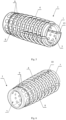
- a medical implant 1 as disclosed in fig. 1 to fig. 3 is provided for insertion into a tunnel socket already made in a femoral bone to enable easy healing of transplants after surgeries associated with reconstruction of ligaments.
- the implant 1 has a body 2 in tubular form with a longitudinal axial throughout conduit 3.
- the implant 1 is made of bioresorbable material, for instance any material from the group of polyactides.
- the conduit 3 has an oval or elliptical cross-section, which makes it possible to achieve a desirable position of the transplanted tendon bunch in the conduit 3 and to introduce an applicator tool therein to screw the implant into the bone tunnel socket.
- edges of the inlets into the conduit 3 are rounded, which diminishes the risk to have the tendon transplant damaged while it is inserted via the conduit.
- the outer surface of the implant body 2 has a protruding crest that forms a screw line serving as a screw thread 4 with a fixed pitch.
- the envelope of the thread 4 in other words the line that is tangent to the crests of the thread 4 in a planar projection, is a straight line 5 down a specific portion of the implant 1 length.
- the remaining portion of the implant 1 length has a thread 4 with an envelope converging toward one end of the implant 1 and having the shape of a parametrical B-splined curve 6 whilst tangency of that curved sections to the straight section 5 of the thread envelope is maintained at the contact point 7 between these two sections.
- the thread 4 envelope converges towards one end of the implant 1 down the section that makes from 40 to 60% of the total length of the implant 1, where the 50% ratio of the converging part is the most preferred.
- the total length of the implant 1 is 30 mm whilst the length of the straight-lined envelope is 15 mm and the length of the envelope with the shape of a parametrical B-splined curve is 15 mm.
- the thread 4 enables axial anchoring of the implant inside a tunnel socket of a bone with potential feasibility to undo the implant when its withdrawal is needed after unsuccessful implantation.
- the thread contributes to strengthening of the implant stiffness and vanishing of the thread down the envelope curve enables gradual engagement of the implant material into the bone tissue.
- orifices 9 made in the wall of the implant body 2 are spaced in every pitch of the thread 4 in the bottom 8 of the thread root. Cross-section of said orifices 9 is convergent towards the axial conduit 3, in particular the orifices have a form of a truncated cone or similar. Throughout orifices 9 enable perfusion of blood and other body fluids into the tendon bunch being transplanted.
- Orifices 9 are regularly spaced down the whole screw line and made in the bottom 8 of the thread 4 root. Symmetry axes of said orifices 9 are normal to the screw line as drawn in points where said orifices are made. These converging orifices 9 enable faster and more intense penetration of blood and other body fluids into the implant with simultaneous reduction of the active inner surface of the conduit 3.
- the surface of the conduit 3 is smoother since the cross-section areas of orifices is less at their outlets into the conduit 3
- the orifice outlets at the side of the central conduit are also rounded and smoothed, which leads to less friction when the transplanted tendon is inserted throughout.
- Fig. 4 to fig. 7 disclose another embodiment of the implant 1, in particular an implant designed for a tibia bone.
- a portion of the implant 1 length starting from its far end opposite to the portion with vanishing thread 4, has at least two longitudinal cuts 10 cut in the body 2 walls.
- the cuts are cut down the section that makes no more than 60% of the total length of the implant 1, where the 50% portion at the most of the cut length is the most preferred embodiment.
- These cuts 10 are designed for controllable outward deflection of the cut section while a bone wedge is inserted into the implant conduit to have the transplanted tendon fixed inside the implant conduit.
- the implant is more reliably anchored in a tunnel socket of a bone.
- Said cuts are also useful when the implant is rotated and fixed by means of an applicator tool.
- the number of cuts 10 can be more than two, for example three or four but it is important to have them symmetrically arranged on the perimeter of the body 2 of the implant 1.
Description
- The invention relates to a medical implant, in particular an implant that is made of bioresorbable material and provided for intensification of healing of transplants into parent tissue after surgeries associated with reconstruction of ligaments in tunnel sockets of bones.
- Patent description
PL 217967 - In turn, patent description
FR 2802083 - In addition patent description
GB 2417536 -
US 2006/100627 discloses a fixation device for securing tissue to a bone. The fixation device includes an anchor having a hollow body defining a longitudinal passage, and a plug configured to be received in at least a portion of the passage. The body comprises a cylindrical portion and a tapered tip portion. The cylindrical portion comprises a plurality of thin-walled window covers such that after implantation the window covers are resorbed first relative to other portions of the cylindrical portion for defining a plurality of apertures on the cylindrical portion. - The medical implant according to the present invention has a body in tubular form with a longitudinal axial throughout conduit whilst the body wall has throughout orifices and the outer surface of the body is provided with a protruding crest that forms a screw line serving as a screw thread, where the envelope of the screw line is a straight line. The essence of the invention consists in the fact that a part of the implant length has a thread with its envelope curve that is convergent towards one end of the implant body and has the form of a parametric B-spline curve whilst tangency of that curved section to the straight section of the thread envelope is maintained at the contact point between these two sections. The throughout orifices made in the wall of the implant body are spaced in every pitch of the thread in the bottom of the thread root. Cross-sections of the orifices made throughout the body walls converge towards the direction of the axial conduit in the implant body, in particular the orifices have the form of a truncated cone.
- Preferably, the thread envelope converges towards one end of the implant and the converges section makes from 40 to 60% of the total length of the implant, most preferably 50% of length of the implant.
- The preferred embodiment of the invention assumes that the implant body has at least two longitudinal cuts cut in the body walls in a portion of the body length at its other end.
- If so, it is desirable that these longitudinal cuts are cut down the length portion of no more than 60% of the total implant length, preferably no more than 50%.
- The medical implant according to the presented invention enable its safe and controllable insertion into a bone tunnel socket owing to its gradually vanishing thread with the thread envelope in the form of a parametrical B-splined curve. Such a form of the thread enables gradual screwing of the implant into a bone tissue, where the load force of the thread increases in proportion to the screwing depth and reliable axial fixation of the implant in the bone tunnel socket is guaranteed. In addition, the crest that makes a screw thread also reinforces the implant stiffness, which compensates its weakening caused by orifices made in the implant body walls. These orifices that converge towards the axial conduit of the implant body are made in the bottom of the thread root and contribute, together with cutting or disruption of bone tissue while the implant is being screwed into the bone tunnel socket, to intensification of blood and other body fluids penetration into the implant interior, which is beneficial to healing efficiency and quickness of ligaments to be reconstructed. In addition, the most preferred embodiment of the invention comprises longitudinal cuts at one side of the implant walls, which enables deflection of implant walls outwardly after the mounting screw is tightened and the implant is additionally fixed in the bone socket. The said cuts can be also used for introduction of an applicator tool with outer ribs engaged with these cuts and make the implant stiffer during its fixing by screwing.
- The invention is disclosed in details in the following embodiments thereof and on relevant drawings, where:
-
Fig. 1 is a side view of the implant; -
Fig. 2 is a perspective view of the implant; -
Fig. 3 is a front view of the implant; -
Fig. 4 is a side view of the implant according to another embodiment of the present invention; -
Fig. 5 and fig. 6 are various perspective views of the implant fromfig. 4 , and -
Fig. 7 is a front view of the implant fromfig. 4 . - A
medical implant 1 as disclosed infig. 1 to fig. 3 is provided for insertion into a tunnel socket already made in a femoral bone to enable easy healing of transplants after surgeries associated with reconstruction of ligaments. Theimplant 1 has abody 2 in tubular form with a longitudinal axial throughoutconduit 3. Theimplant 1 is made of bioresorbable material, for instance any material from the group of polyactides. Theconduit 3 has an oval or elliptical cross-section, which makes it possible to achieve a desirable position of the transplanted tendon bunch in theconduit 3 and to introduce an applicator tool therein to screw the implant into the bone tunnel socket. Preferably, edges of the inlets into theconduit 3 are rounded, which diminishes the risk to have the tendon transplant damaged while it is inserted via the conduit. The outer surface of theimplant body 2 has a protruding crest that forms a screw line serving as ascrew thread 4 with a fixed pitch. The envelope of thethread 4, in other words the line that is tangent to the crests of thethread 4 in a planar projection, is astraight line 5 down a specific portion of theimplant 1 length. However, the remaining portion of theimplant 1 length has athread 4 with an envelope converging toward one end of theimplant 1 and having the shape of a parametrical B-splinedcurve 6 whilst tangency of that curved sections to thestraight section 5 of the thread envelope is maintained at thecontact point 7 between these two sections. In particular thethread 4 envelope converges towards one end of theimplant 1 down the section that makes from 40 to 60% of the total length of theimplant 1, where the 50% ratio of the converging part is the most preferred. For example the total length of theimplant 1 is 30 mm whilst the length of the straight-lined envelope is 15 mm and the length of the envelope with the shape of a parametrical B-splined curve is 15 mm. Thethread 4 enables axial anchoring of the implant inside a tunnel socket of a bone with potential feasibility to undo the implant when its withdrawal is needed after unsuccessful implantation. In addition, the thread contributes to strengthening of the implant stiffness and vanishing of the thread down the envelope curve enables gradual engagement of the implant material into the bone tissue. Throughoutorifices 9 made in the wall of theimplant body 2 are spaced in every pitch of thethread 4 in thebottom 8 of the thread root. Cross-section ofsaid orifices 9 is convergent towards theaxial conduit 3, in particular the orifices have a form of a truncated cone or similar. Throughoutorifices 9 enable perfusion of blood and other body fluids into the tendon bunch being transplanted.Orifices 9 are regularly spaced down the whole screw line and made in thebottom 8 of thethread 4 root. Symmetry axes of saidorifices 9 are normal to the screw line as drawn in points where said orifices are made. Theseconverging orifices 9 enable faster and more intense penetration of blood and other body fluids into the implant with simultaneous reduction of the active inner surface of theconduit 3. In addition, the surface of theconduit 3 is smoother since the cross-section areas of orifices is less at their outlets into theconduit 3 Preferably, the orifice outlets at the side of the central conduit are also rounded and smoothed, which leads to less friction when the transplanted tendon is inserted throughout. -
Fig. 4 to fig. 7 disclose another embodiment of theimplant 1, in particular an implant designed for a tibia bone. On the contrary to the first embodiment, a portion of theimplant 1 length, starting from its far end opposite to the portion with vanishingthread 4, has at least twolongitudinal cuts 10 cut in thebody 2 walls. The cuts are cut down the section that makes no more than 60% of the total length of theimplant 1, where the 50% portion at the most of the cut length is the most preferred embodiment. Thesecuts 10 are designed for controllable outward deflection of the cut section while a bone wedge is inserted into the implant conduit to have the transplanted tendon fixed inside the implant conduit. In consequence, the implant is more reliably anchored in a tunnel socket of a bone. Said cuts are also useful when the implant is rotated and fixed by means of an applicator tool. The number ofcuts 10 can be more than two, for example three or four but it is important to have them symmetrically arranged on the perimeter of thebody 2 of theimplant 1.
Claims (4)
- A medical implant (1), made of bioresorbable material, provided for intensification of healing of transplants into parent tissue after surgeries associated with reconstruction of ligaments in tunnel sockets of bones, where an implant body (2) is a tube with a longitudinal throughout conduit (3), whilst throughout orifices (9) are made in the body (2) wall, and the outer surface of the body (2) is provided with a protruding crest that forms a screw line serving as a screw thread (4), where the envelope of the screw line is a straight line (5), and a part of the implant length has a thread (4) with its envelope curve convergent towards one end of the implant (1) which envelope has the form of a parametric B-spline curve (6), whilst tangency of that curved sections to the straight section (5) of the thread envelope is maintained at the contact point (7) between these two sections, and the throughout orifices (9) made in the wall of the implant body (2) are spaced in every pitch of the thread (4) in the bottom (8) of the thread root, characterized in that orifices (9) made in wall of the implant body (2) have cross-sections converging towards the axial conduit (3) of the implant body (2), in particular the orifices have a form of truncated cones.
- The implant according to claim 1, characterized in that the envelope of the thread (4) converges towards one end of the implant (1) down the section with the length from 40% to 60% of the total implant (1) length, most preferably 50% portion of the total implant (1) length.
- The implant according to claim 1 or 2, characterized in that the wall of the implant body (2) has at least two longitudinal cuts (10) that are cut down in a portion of the implant (1) length at its other end.
- The implant according to claim 3, characterized in that cuts (10) are made down the portion of not more than 60% of the total implant (1) length, most preferably not more than 50%.
Applications Claiming Priority (1)
| Application Number | Priority Date | Filing Date | Title |
|---|---|---|---|
| PL423335A PL423335A1 (en) | 2017-10-31 | 2017-10-31 | Medical implant |
Publications (3)
| Publication Number | Publication Date |
|---|---|
| EP3501452A1 EP3501452A1 (en) | 2019-06-26 |
| EP3501452B1 true EP3501452B1 (en) | 2024-02-21 |
| EP3501452B8 EP3501452B8 (en) | 2024-05-01 |
Family
ID=66223556
Family Applications (1)
| Application Number | Title | Priority Date | Filing Date |
|---|---|---|---|
| EP18191986.1A Active EP3501452B8 (en) | 2017-10-31 | 2018-08-31 | Medical implant |
Country Status (2)
| Country | Link |
|---|---|
| EP (1) | EP3501452B8 (en) |
| PL (1) | PL423335A1 (en) |
Family Cites Families (8)
| Publication number | Priority date | Publication date | Assignee | Title |
|---|---|---|---|---|
| US4255820A (en) * | 1979-07-24 | 1981-03-17 | Rothermel Joel E | Artificial ligaments |
| US6099530A (en) * | 1998-04-09 | 2000-08-08 | Smith & Nephew, Inc. | Soft-tissue intra-tunnel fixation device |
| DE59900298D1 (en) * | 1999-10-21 | 2001-11-08 | Storz Karl Gmbh & Co Kg | Biodegradable fixation body |
| FR2802083B1 (en) * | 1999-12-13 | 2002-01-11 | Jean Jacques Martin | ANCHORING IMPLANT FOR A PROTHETIC OR NATURAL LIGAMENT |
| US6730124B2 (en) * | 2002-03-08 | 2004-05-04 | Musculoskeletal Transplant Foundation | Bone-tendon-bone assembly with cancellous allograft bone block |
| WO2005069884A2 (en) * | 2004-01-16 | 2005-08-04 | Osteobiologics, Inc. | Bone-tendon-bone implant |
| GB2417536B (en) * | 2004-08-28 | 2006-09-06 | Adam James | A bioabsorable screw |
| US7914539B2 (en) * | 2004-11-09 | 2011-03-29 | Biomet Sports Medicine, Llc | Tissue fixation device |
-
2017
- 2017-10-31 PL PL423335A patent/PL423335A1/en unknown
-
2018
- 2018-08-31 EP EP18191986.1A patent/EP3501452B8/en active Active
Also Published As
| Publication number | Publication date |
|---|---|
| EP3501452A1 (en) | 2019-06-26 |
| EP3501452B8 (en) | 2024-05-01 |
| PL423335A1 (en) | 2019-05-06 |
Similar Documents
| Publication | Publication Date | Title |
|---|---|---|
| US11478287B2 (en) | Fenestrated implant | |
| US11678997B2 (en) | Implants for spinal fixation and or fusion | |
| US9956013B2 (en) | Systems and methods for the fixation or fusion of bone | |
| JP5443398B2 (en) | Bone screw | |
| US7914539B2 (en) | Tissue fixation device | |
| US7608098B1 (en) | Bone fixation device | |
| JP2020519413A (en) | Implants for tissue fixation and fusion | |
| US20050216012A1 (en) | Bone pin | |
| US5593446A (en) | Anchoring shaft for joint endoprosthesis | |
| US10940008B2 (en) | Implant for bone segment fusion | |
| US20130030479A1 (en) | Bone wedge | |
| US20200205870A1 (en) | Cannulated fixation device | |
| US10251683B2 (en) | Intramedullary nail | |
| EP3501452B1 (en) | Medical implant | |
| US20200246051A1 (en) | Orthopaedic implant with fixation feature and a method of implanting thereof | |
| US20190059960A1 (en) | Two part hammertoe implant with expandable tines | |
| US10751100B2 (en) | Bone screws and surgical sets comprising bone screws | |
| JP2020517320A (en) | Longitudinal bone implant | |
| CN115916078A (en) | Bone anchoring implant with cortical stabilization | |
| CN115768376B (en) | Bone anchoring implant with optimized expansion | |
| US20210275307A1 (en) | Surgical implant | |
| CN110101446B (en) | Extrusion nail with self-locking function | |
| CN210277316U (en) | Extrusion nail with self-locking function and assembly tool of extrusion nail | |
| CN213217548U (en) | Interface screw | |
| PL229715B1 (en) | Two-part implant for direct connection of bone with the limb prosthesis |
Legal Events
| Date | Code | Title | Description |
|---|---|---|---|
| PUAI | Public reference made under article 153(3) epc to a published international application that has entered the european phase |
Free format text: ORIGINAL CODE: 0009012 |
|
| STAA | Information on the status of an ep patent application or granted ep patent |
Free format text: STATUS: THE APPLICATION HAS BEEN PUBLISHED |
|
| AK | Designated contracting states |
Kind code of ref document: A1 Designated state(s): AL AT BE BG CH CY CZ DE DK EE ES FI FR GB GR HR HU IE IS IT LI LT LU LV MC MK MT NL NO PL PT RO RS SE SI SK SM TR |
|
| AX | Request for extension of the european patent |
Extension state: BA ME |
|
| STAA | Information on the status of an ep patent application or granted ep patent |
Free format text: STATUS: REQUEST FOR EXAMINATION WAS MADE |
|
| 17P | Request for examination filed |
Effective date: 20191216 |
|
| RBV | Designated contracting states (corrected) |
Designated state(s): AL AT BE BG CH CY CZ DE DK EE ES FI FR GB GR HR HU IE IS IT LI LT LU LV MC MK MT NL NO PL PT RO RS SE SI SK SM TR |
|
| GRAP | Despatch of communication of intention to grant a patent |
Free format text: ORIGINAL CODE: EPIDOSNIGR1 |
|
| STAA | Information on the status of an ep patent application or granted ep patent |
Free format text: STATUS: GRANT OF PATENT IS INTENDED |
|
| INTG | Intention to grant announced |
Effective date: 20230908 |
|
| GRAS | Grant fee paid |
Free format text: ORIGINAL CODE: EPIDOSNIGR3 |
|
| GRAA | (expected) grant |
Free format text: ORIGINAL CODE: 0009210 |
|
| STAA | Information on the status of an ep patent application or granted ep patent |
Free format text: STATUS: THE PATENT HAS BEEN GRANTED |
|
| AK | Designated contracting states |
Kind code of ref document: B1 Designated state(s): AL AT BE BG CH CY CZ DE DK EE ES FI FR GB GR HR HU IE IS IT LI LT LU LV MC MK MT NL NO PL PT RO RS SE SI SK SM TR |
|
| REG | Reference to a national code |
Ref country code: GB Ref legal event code: FG4D |
|
| REG | Reference to a national code |
Ref country code: CH Ref legal event code: EP |
|
| REG | Reference to a national code |
Ref country code: DE Ref legal event code: R096 Ref document number: 602018065453 Country of ref document: DE |
|
| REG | Reference to a national code |
Ref country code: IE Ref legal event code: FG4D |
|
| GRAT | Correction requested after decision to grant or after decision to maintain patent in amended form |
Free format text: ORIGINAL CODE: EPIDOSNCDEC |
|
| REG | Reference to a national code |
Ref country code: NL Ref legal event code: FP |
|
| P01 | Opt-out of the competence of the unified patent court (upc) registered |
Effective date: 20240306 |
|
| REG | Reference to a national code |
Ref country code: CH Ref legal event code: PK Free format text: BERICHTIGUNG B8 Ref country code: CH Ref legal event code: PK Free format text: BERICHTIGUNGEN |