EP3501451B1 - Halterung für labornager - Google Patents
Halterung für labornager Download PDFInfo
- Publication number
- EP3501451B1 EP3501451B1 EP16913652.0A EP16913652A EP3501451B1 EP 3501451 B1 EP3501451 B1 EP 3501451B1 EP 16913652 A EP16913652 A EP 16913652A EP 3501451 B1 EP3501451 B1 EP 3501451B1
- Authority
- EP
- European Patent Office
- Prior art keywords
- grille
- frame
- rodent
- tail
- supportive
- Prior art date
- Legal status (The legal status is an assumption and is not a legal conclusion. Google has not performed a legal analysis and makes no representation as to the accuracy of the status listed.)
- Active
Links
Images




Classifications
-
- A—HUMAN NECESSITIES
- A61—MEDICAL OR VETERINARY SCIENCE; HYGIENE
- A61D—VETERINARY INSTRUMENTS, IMPLEMENTS, TOOLS, OR METHODS
- A61D3/00—Arrangements for supporting or fettering animals for veterinary purposes
Definitions
- the present invention belongs to animal experimental equipment in medical and biological fields, and mainly relates to an improvement of a laboratory rodent holding device.
- a laboratory rodent holding device is an essential equipment for handling awake rodents as experimental subjects. Products or solutions with various structures have been introduced for users to choose and have provided some convenience for animal experiments.
- the patent application CN201310171492A (Yan Tiebin, 2014 ) discloses a three-dimensional adjustment animal restraining and fixing device, which is composed of a bottom plate and a clamping mechanism provided with a connecting unit and a restraining unit.
- the utility model CN204133638U (Zhuang Baoxiang, 2015 ) discloses a rat fixation device for intragastric gavage, comprising fixing and coupling parts, namely two clamping wings connected through a fixing shaft, plural grasping teeth, a head fixing plate and an arm protection cover.
- the object of the present invention is to overcome the above-mentioned limitations and develop a rodent-holder allowing for a larger exposure of bodily area with a concomitant reliable restriction of a rodent, hence meeting wider operational needs of an experiment.
- the present invention proposes a technical solution with such performance for the pointed technical problems to be solved.
- the rodent holder includes a frame, a rodent body-restrainer associated with the frame body, and coupling components connecting the frame and the restrainer.
- the restrainer is a grille-shaped component with two halves functioning together in a clamped manner, imitating or approximating the outer shape of a rodent and restricting it at its position
- the coupling components further comprise adjustment components capable of changing the position of the grille.
- a grille resembling or approximating the shape and size of a rodent body ensures the fitness and vicinity of the grille to the corresponding part of the rodent body. Adjusting the position of the grille-type restrainer is required for the grille to effectively clamp and relax a rodent body, to adapt to variable rodent bodies of different sizes, to stably and reliably limit the movement of the rodent, and to timely release the rodent at the completion of an experiment.
- the grille-type restrainer can also significantly reduce the coverage of a rodent body and expose more bodily area, thereby stabilizing body temperature and facilitating experimental operations. The object of the present invention is thus achieved and the raised technical problems are solved.
- the object of the present invention can be further achieved by the following scheme.
- the connecting components of the present invention comprise of pairs of sliding bars that can adjust and fix the position of the grille-shaped restrainer alongside the rod-type frame or the relative positions between the two halves of the grille, pairs of sliding bars and pairs of one- or two-way screws to adjust the positions of the sliding bars, and pairs of ratchet-ratchet couplings that can adjust the relative shape or angles of each grille finger.
- the pairs of sliding bars, screws and ratchets are all coupling pairs that can change the relative positions of the connected components, that is, to change the relative positions between the fixed and movable components, between the active and the passive components, or between the ratchets; and the sliding or moving couplings can also be fixed at a new position towards each other. Due to the structural characteristics of the two-way screws and the ratchet-ratchet coupling pairs, the two mating halves of the grille can be relatively fixed after adjustment; the two-way screws with opposite transmission directions can move the coupling parts towards or away from each other, endowing a higher adjustment efficiency while adjusting the relative position.
- the present invention is provided with a supportive standing plate that is connected to the front of a frame below a grille, or with a supportive rail connected to the lower end of each grille finger, for an experimental rodent to enter into the clamping position. Both the plate and the rail can help the experimental rodent to enter or exit the rodent holder before and after being restrained.
- the frame of the present invention is a rod-like structure and has detachable and adjustable supportive legs that can uphold it in either a downside-up or an up-side down manner.
- the rod structure can leave more space and provide more convenience to an experimenter.
- the frame can not only still maintain the support to the hanged restrainer in its flipped position, but also turn what is beneath the grille upwards, thereby making the abdomen of a rodent body held by the grille facing upward. This provides more convenience for an experimenter; the removable supportive legs facilitate a downside-up or upside-down conversion of the frame and the grille, meeting an experiment with such needs, increasing operational options, and are easy to mount, transport and store.
- a removable tail plate that is connected to and adjusted in its relative horizontal position to the frame via a vertical plate is provided.
- the height of the tail plate can also be adjusted according to the heights of the frame plane and the restrained rodent body.
- the tail plate has a slit for placing a rodent tail on its surface.
- An illuminating and heating light source is provided below the plate underneath the slit.
- a glass magnifier is anchored on the tail plate above the slit, whose position is adjustable in relative position to the tail plate.
- a tail plate belongs to the extension of the frame of a rodent holder, that is, it is for the fixation of a rodent tail.
- a light bulb underneath the slit can illuminate and dilate the tail veins through heating, which eases a tail operation.
- a glass magnifier above the slit improves an experimenter's vision of the tail.
- An adjustable cooperation between the tail plate and the frame in both horizontal and vertical directions can meet the needs of various experimental operations.
- the present invention utilizes a contouring grille fit for different rodents, various types of adjustable components for changing the position of the grille, a supportive standing plate or a finger-connecting rail, a frame and its removable and adjustable supportive legs.
- the holder can adapt to various bodily shapes and sizes, and is easy to operate. While restraining a rodent, the holder leaves a largely exposed bodily area of the rodent, thereby fitting various rodent experiments; Its reversed position also increases the flexibility of the use of the device, so that the ventral side of arodent body can be placed in a convenient operable position.
- the glass magnifier placed above the tail improves the visual environment of the operation, bringing a fuller range of operation on the restricted rodent.
- the device is simple and unique in its structure, making it easy to manufacture, install and use.
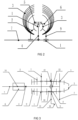
- the frame body (7) of the present example is a -shaped rod structure on a horizontal plane.
- the two sliding bars on the same flanking side of the central vertical rod are connected to each other by a connecting rod (10), and in total two connecting rods.
- the two connecting rods are further linked with each other in the middle via a two-way screw bolt (13) that can rotate in opposite axial directions in parallel to the two horizontal rods of the frame body, together with a screw rod (11) that has two opposite axial directions matching the corresponding two-way screw bolt, as shown in Figure 3 .
- a pair of stopping bars (12) are connected to the central vertical rod of the frame to stop moving of the screw bolt alongside the screw rod.
- a turning handle (15) that is connected and can rotate the screw rod along its axial direction is also installed.
- the upper ends of the two pillars on either side of the central vertical rod of the frame are respectively fixed with a grille beam (2).
- the beam can be contoured at the corresponding bodily portion of a stepped-in rodent.
- a rake of multiple grille fingers (3) that contour around the corresponding portions of a rodent body are fixed at different positions alongside each beam.
- the grille fingers stand perpendicularly on the beam relative to the frame plane, and the fingers between the two beams are positioned to be able to close each other.
- a combination of various pillars, beams and fingers can be provided. In order to improve the effect of clamping and fixing, it is also considerable to apply a soft material onto the inner surfaces of the beams and fingers, or to select a flexible material that is minimally irritating to rodents for the beams and fingers.
- a detachable sliding bar that moves axially alongside the vertical rod is connected.
- a short vertical plate (4) perpendicular to the frame plane is anchored onto the sliding bar, and the vertical plate can be connected to a supportive rod along either side of the central vertical rod of the frame, which can contact the second horizontal rod of the frame to stabilize the vertical plate.
- a detachable sliding bar moving upwards or downwards along the vertical plate is also inserted.
- the sliding bar is fixedly connected to ahorizontal tail plate (6) at the rear of the frame.
- a tail slit (14) on the tail plate in the longitudal direction of the central vertical rod of the frame is cut, and its width is narrower than the average diameter of a rodent tail.
- a glass magnifier (5) can be connected onto the tail plate and above the slit, and an illuminating and heating light pulp can be arranged below the tail plate and underneath the slit.
- a detachable limiting hinge (8) that can fold the rear part of the central vertical rod in perpendicular to its longitudinal direction, thereby dividing it into two connecting parts, can be installed.
- a detachable chord (19) defining the two parts of the rod in a rectangular relationship can be also provided.
- the rear half of the central vertical rod is slightly longer than the distance from the top end of the longest grille finger to the frame plane.
- additional supportive legs (16) having the same length as the rear half of the central vertical rod are provided as an attachment of the embodiment.
- One end of the supportive leg has a tube (17) that can be connected to the horizontal rod of the frame, and the axis of the tube is perpendicular to the longitudinal direction of the supportive leg;
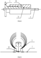
- the other end of the supportive leg is hingedly or fixedly connected to three supportive feet (18), as shown in Figure 4 and Figure 5 .
- a suitable grille with the set of sliding bars-pillars, grille beams and grille fingers that fit the body shape and size of an experimental rodent is selected and assembled, and the experimental animalis made to enter into the grille from the planar frame.
- a turning handle is turned to rotate a two-way screw so that the two halves of the grille, namely including the sliding bars-pillars, the grille beams and the grille fingers, move towards each other through the connecting rods of the sliding bars-pillars until the experimental animal is restrained, and a following experimental operation can be proceeded.
- an experimental operation is on the back of a restrained rodent, such as a subcutaneous injection, the skin area required for the operation can be exposed because of large gaps between the grill fingers on the back side.
- an experimental operation involves the abdominal part of the animal, such as an intraperitoneal injection, then the rear part of the central vertical rod of the frame can be folded at its hinge site, with the folded vertical rod stabilized by a rectangular chord, and accessory supportive legs can be connected to the horizontal rods of the frame via their end tubes. The device is then turned over so that the folded central vertical rod and the supportive legs can jointly uphold the inverted frame.
- a restrained animal is in a supine posture with its belly exposed, and an experimenter can perform the corresponding operation.
- a tail plate and a vertical plate together with its sliding bars are mounted onto the central vertical rod of the frame before an experiment.
- the vertical plate and the tail plate are adjusted to place the tail at a proper position.
- the tail is placed above the slit on the tail plate, with an underneath illumination LED light and an above glass magnifier to aid the tail vein injection or blood collection.
- the turning handle is turned in a reversed direction to open the grille and release the restrained animal. The animal can recover a bit on the planar frame, and an experiment is concluded.
- the body- and tail-fixing components of the present grille-type exemplar device provide an all-round fixed state for an experimental rodent; the hinged structure of the rear part of the central vertical rod together with the accessory supportive legs enable the device to have a reverted position; the glass magnifier improves the visual effect; the device can bring a full operational convenience to an experiment, and its structure is simple, unique, convenient to manufacture, install and use.
- the outstanding technical features of the above exemplar device are: 1) It is flexibly fit for multiple purposes and three-dimensional adjustment, the grille and the frame are freely coupled and detached; 2) The grille can fix the body of a rodent and enclose its head well, hence an experimenter can avoid being bitten by the animal, and the restraint effect is good enough while bringing little harm to the rodent; 3) The grille is slidable and detachable, and can be used for restraining both rats and mice; 4) The height and position of the tail plate can be individually adjusted according the hip size of an animal to ensure a horizontal positioning of its tail on the plate, which eases tail operation; 5) The tail slit is designed according to the physiological feature of a rodent tail, and accompanied by a heating light and a magnifier, helps identify the tail veins to improve the success rate of operation; 6) A detachable illuminating system makes the device easy to clean and sterilize; 7) The structure of the device is simple and reasonable, making it easy to operate.
- the laboratory rodent holder is further equipped with fixable sliding bars.
- the coupling between the grille and the frame is realized via pairs of sliding bars-pillars whose positions can be controlled by a tightening structure instead of a two-way screw bolt.
- the tightening structure can like a leash release the sliding gap between a sliding bar-pillar and a horizontal frame rod.
- the tightening leash eliminates the sliding gap and gives a certain level of pressure to the sliding bar-pillar to reinforce its fixed state and position as required for restraining an experimental animal.
- This tightening structure can be an ejectable knob between the sliding partners, pushed-in when sliding is needed and pushed-out when fixation is required. It can also be just a set of screws on the sliding bars-pillars, a screw is loosened when the sliding bar-pillar is to be moved and tightened when to be fixed.
- the laboratory rodent holder further comprises a ratchet-ratchet coupling pair, which is installed in the middle of each grille finger, making a joint to it. Adjusting the matching teeth positions between the two ratchets can change the bending state of the fingers and thereby the shape of the grille, while releasing the coupled ratchets on the fingers can restore the original state of the grille. This functions to adjust the body-contour shape of the grille.
- a groove can be made on the horizontal rods of a frame, and the relative position of a sliding bar-pillar alongside the rod can be manually adjusted by its connecting bolt inside the groove.
- the rodent holder can be equipped with three supportive legs.
- the rear half of the central vertical rod of a frame does not have a folding hinge.
- the third supportive leg is structurally the same as the two supportive legs as described in the first exemplar rodent holder, and can be connected to the rear end of the central vertical rod, allowing for a reverse support of the device.
- the rodent holder can be equipped with a tapered mating sliding bars, see Figure 8 .
- a taper core (21) is slidably engaged with the frame body or the grille beam.
- the tapered tube of the first half of the taper core has a slit in its axial direction and is discontinuous in the circumferential direction.
- the tapered tube of the second half of the taper core has a screw direction matched with that in a taper sleeve (20).
- the inner hole of the first half of the taper sleeve is a tapered hole that cooperates with the first half of the taper core.
- the tapered hole is separated from the taper core, and the taper core can slide freely on the horizontal rod of the frame or the grill beam; when the taper sleeve is screwed, it encloses towards the taper core until the circumferential gaps in the taper core are narrowed by the sliding, and the taper hole is also reduced.
- a further tightening of the taper sleeve can fix their relative positions toward each other.
- the position of a sliding bar-pillar connected with the taper sleeve is also fixed on the horizontal rod of the frame.
- the sliding bar-pillar connected with the taper sleeve can be uncoupled with the horizontal rod of the frame or repositioned, and a restraint rodent can be released.
- the rodent holder can be equipped with a supportive frontal standing plate.
- a standing plate (22) is connected to the front of a frame, see Figure 9 .
- the plate is L-shaped and has grooves on its one wing corresponding to the positions of the central rod of the frame and the grille beams. In its use, the central rod and beams are inserted into the grooved wing of the standing plate and the other wing is connected horizontally to the frame, making it a supportive standing place for a rodent. After clamping of the grille, the plate can be removed. This helps for an easy entry and exit of the grille for a rodent.
- the rodent holder can be equipped with a supportive rail (22) on the grille, as shown in Figure 9 .
- a supportive rail is connected to the grille beam and the associated grille fingers on the same side, which laterally extends towards each other to form a full rail when the grille is closed.
- the rail is at a height suitable for a rodent to stand on and step in and out of the grille.
- the rodent holder can be equipped with supportive legs of adjustable heights, see Figure 10 .
- multiple supportive legs of adjustable heights can be connected to the frame.
- the frame is supported by the legs, and the heights of the legs can be adjusted so that the flanking side of a restrained rodent's body is likely to be seen at different positions. This design meets an experiment with such a need.
Landscapes
- Life Sciences & Earth Sciences (AREA)
- Health & Medical Sciences (AREA)
- Veterinary Medicine (AREA)
- Animal Husbandry (AREA)
- Engineering & Computer Science (AREA)
- Wood Science & Technology (AREA)
- Zoology (AREA)
- Animal Behavior & Ethology (AREA)
- General Health & Medical Sciences (AREA)
- Public Health (AREA)
- Catching Or Destruction (AREA)
Claims (4)
- Der Labor-Nagetierhalter mit einem Rahmen (7), einem Befestigungselement zur Einschränkung der Bewegung eines Nagetierkörpers und Kopplungselementen, die den Rahmen und das Befestigungselement verbinden, wobei das Befestigungselement ein gitterförmiger Halter mit zwei Hälften ist, die einen Nagetierkörper imitieren oder sich diesem annähern und mit Gitterträgern (2) und Gitterfingern (3) ausgestattet sind, die mit dem Rahmen (7) verbunden sind, und der hintere Teil des Rahmens (7) eine horizontale, abnehmbare Heckplatte (6) mit einem Heckschlitz (14), dessen Positionen in Bezug auf den Gitterträger (2) und den Rahmen (7) einstellbar sind, und eine vertikale Platte (4) mit Verbindungselementen, wobei die Verbindungselemente Einstellkomponenten umfassen, um die Position des gitterförmigen Halters zu ändern, und die vorgenannten Einstellkomponenten umfassen Paare von Gleitstäben, Einweg- oder Zweiweg-Schraubenpaare mit entgegengesetzten Übertragungsrichtungen und Ratschen-Kupplungspaare zur Änderung der relativen Positionen zwischen verschiedenen Teilen eines einzigen Gitterfingers (3).
- Der Labor-Nagetierhalter nach Anspruch 1 oder 2, der außerdem eine stützende Standplatte (22) unterhalb des Gitterträgers (2), die mit dem Rahmen (7) verbunden ist, oder eine stützende Schiene (22) umfasst, die mit dem unteren Ende jedes Gitterfingers (3) verbunden ist, um Nagetiere in den Nagetierhalter hinein- oder herauszulassen.
- Der Labor-Nagetierhalter nach einem der vorhergehenden Ansprüche, wobei der Rahmen (7) eine Stabstruktur ist und mit Stützbeinen (16) ausgestattet ist, die den Rahmen (7) entweder in einer nach unten oder nach oben zeigenden Position halten.
- Der Labor-Nagetierhalter nach einem der vorhergehenden Ansprüche umfasst außerdem eine unterhalb der Schwanzplatte (6) unterhalb des Schwanzschlitzes (14) angebrachte Beleuchtungs- und Heizlichtquelle und eine auf der Schwanzplatte (6) oberhalb des Schwanzschlitzes (14) angeordnete Lupe, deren Position einstellbar ist.
Applications Claiming Priority (1)
| Application Number | Priority Date | Filing Date | Title |
|---|---|---|---|
| PCT/CN2016/096121 WO2018035628A1 (zh) | 2016-08-21 | 2016-08-21 | 实验鼠固定器 |
Publications (4)
| Publication Number | Publication Date |
|---|---|
| EP3501451A1 EP3501451A1 (de) | 2019-06-26 |
| EP3501451A4 EP3501451A4 (de) | 2020-02-26 |
| EP3501451C0 EP3501451C0 (de) | 2023-06-21 |
| EP3501451B1 true EP3501451B1 (de) | 2023-06-21 |
Family
ID=61245869
Family Applications (1)
| Application Number | Title | Priority Date | Filing Date |
|---|---|---|---|
| EP16913652.0A Active EP3501451B1 (de) | 2016-08-21 | 2016-08-21 | Halterung für labornager |
Country Status (2)
| Country | Link |
|---|---|
| EP (1) | EP3501451B1 (de) |
| WO (1) | WO2018035628A1 (de) |
Families Citing this family (1)
| Publication number | Priority date | Publication date | Assignee | Title |
|---|---|---|---|---|
| CN113768651A (zh) * | 2021-08-11 | 2021-12-10 | 赣南医学院第一附属医院 | 一种用于制作大鼠缺血性脑损伤模型的固定装置 |
Family Cites Families (9)
| Publication number | Priority date | Publication date | Assignee | Title |
|---|---|---|---|---|
| US4140082A (en) * | 1977-11-25 | 1979-02-20 | Easton Harlan J | Animal holder |
| US5320069A (en) * | 1992-04-28 | 1994-06-14 | The United States Of America As Represented By The Secretary Of The Army | Small animal restraint device |
| CN201119925Y (zh) * | 2007-11-26 | 2008-09-24 | 牛廷献 | 手持大白鼠固定器 |
| CN101953719A (zh) * | 2010-08-20 | 2011-01-26 | 秦国秀 | 多功能实验动物(鼠)采血解剖放大仪 |
| CN202605050U (zh) * | 2012-05-30 | 2012-12-19 | 佳木斯大学 | 一种限制大鼠翻转的固定装置 |
| CN104068944A (zh) * | 2013-03-26 | 2014-10-01 | 燕铁斌 | 一种三维调节的动物约束固定装置及其约束方法 |
| CN204133638U (zh) * | 2014-09-26 | 2015-02-04 | 潍坊医学院 | 大鼠灌胃用固定装置 |
| CN204121198U (zh) * | 2014-10-15 | 2015-01-28 | 谭曜 | 一种兔子皮肤试验固定装置 |
| CN105616034B (zh) * | 2016-03-24 | 2017-11-17 | 周飞虎 | 一种大鼠操作平台 |
-
2016
- 2016-08-21 WO PCT/CN2016/096121 patent/WO2018035628A1/zh not_active Ceased
- 2016-08-21 EP EP16913652.0A patent/EP3501451B1/de active Active
Also Published As
| Publication number | Publication date |
|---|---|
| EP3501451C0 (de) | 2023-06-21 |
| EP3501451A4 (de) | 2020-02-26 |
| EP3501451A1 (de) | 2019-06-26 |
| WO2018035628A1 (zh) | 2018-03-01 |
Similar Documents
| Publication | Publication Date | Title |
|---|---|---|
| US9304285B2 (en) | Catheterization aid for women | |
| CN105147413A (zh) | 一种针对中小型动物颈椎手术的解剖台 | |
| EP3501451B1 (de) | Halterung für labornager | |
| CN205054497U (zh) | 一种可调节头架角度的实验动物手术解剖台 | |
| CN211934419U (zh) | 畜牧用口腔撑开装置 | |
| CN110680550A (zh) | 一种用于动物医学实验的解剖台 | |
| CN211381936U (zh) | 大鼠膝关节炎动物模型制备及药物干预辅助装置 | |
| CN221556110U (zh) | 一种畜牧兽医喂药器 | |
| CN201668530U (zh) | 多功能家兔手术固定装置 | |
| CN209108059U (zh) | 一种新型艾灸固定防护装置 | |
| CN219516978U (zh) | 腿部支架及腿部支撑装置 | |
| CN213310564U (zh) | 一种多功能实验鼠类固定装置 | |
| CN104096317B (zh) | 医疗辐照装置 | |
| CN108542539A (zh) | 一种畜牧兽医手术操作台 | |
| CN213821860U (zh) | 一种兽医用具有防抓咬结构的手术辅助装置 | |
| CN207654185U (zh) | 一种可调控手术切口牵开器 | |
| CN219042811U (zh) | 一种高效的无级调节大鼠夹持装置 | |
| CN216962737U (zh) | 一种兽医检查用牲畜口腔撑开装置 | |
| CN120036986B (zh) | 一种畜牧兽医用畜牧口腔撑开器 | |
| CN216164745U (zh) | 一种带有组合式结构的兽医人员用防抓伤防护装置 | |
| CN221750943U (zh) | 一种畜牧兽医用畜牧口腔撑开器具 | |
| CN224206931U (zh) | 一种用于暴露小鼠颈部/腹部的手术固定台 | |
| CN115990070B (zh) | 一种大小鼠肢体骨骼造模用固定装置 | |
| CN222815904U (zh) | 一种动物实验用动物固定装置 | |
| CN217138339U (zh) | 一种兽医用去势钳 |
Legal Events
| Date | Code | Title | Description |
|---|---|---|---|
| STAA | Information on the status of an ep patent application or granted ep patent |
Free format text: STATUS: THE INTERNATIONAL PUBLICATION HAS BEEN MADE |
|
| PUAI | Public reference made under article 153(3) epc to a published international application that has entered the european phase |
Free format text: ORIGINAL CODE: 0009012 |
|
| STAA | Information on the status of an ep patent application or granted ep patent |
Free format text: STATUS: REQUEST FOR EXAMINATION WAS MADE |
|
| 17P | Request for examination filed |
Effective date: 20190320 |
|
| AK | Designated contracting states |
Kind code of ref document: A1 Designated state(s): AL AT BE BG CH CY CZ DE DK EE ES FI FR GB GR HR HU IE IS IT LI LT LU LV MC MK MT NL NO PL PT RO RS SE SI SK SM TR |
|
| AX | Request for extension of the european patent |
Extension state: BA ME |
|
| RAP1 | Party data changed (applicant data changed or rights of an application transferred) |
Owner name: LITROD OUE |
|
| DAV | Request for validation of the european patent (deleted) | ||
| DAX | Request for extension of the european patent (deleted) | ||
| A4 | Supplementary search report drawn up and despatched |
Effective date: 20200128 |
|
| RIC1 | Information provided on ipc code assigned before grant |
Ipc: A61D 3/00 20060101AFI20200122BHEP |
|
| STAA | Information on the status of an ep patent application or granted ep patent |
Free format text: STATUS: EXAMINATION IS IN PROGRESS |
|
| 17Q | First examination report despatched |
Effective date: 20201119 |
|
| GRAP | Despatch of communication of intention to grant a patent |
Free format text: ORIGINAL CODE: EPIDOSNIGR1 |
|
| STAA | Information on the status of an ep patent application or granted ep patent |
Free format text: STATUS: GRANT OF PATENT IS INTENDED |
|
| INTG | Intention to grant announced |
Effective date: 20230111 |
|
| GRAS | Grant fee paid |
Free format text: ORIGINAL CODE: EPIDOSNIGR3 |
|
| GRAA | (expected) grant |
Free format text: ORIGINAL CODE: 0009210 |
|
| STAA | Information on the status of an ep patent application or granted ep patent |
Free format text: STATUS: THE PATENT HAS BEEN GRANTED |
|
| AK | Designated contracting states |
Kind code of ref document: B1 Designated state(s): AL AT BE BG CH CY CZ DE DK EE ES FI FR GB GR HR HU IE IS IT LI LT LU LV MC MK MT NL NO PL PT RO RS SE SI SK SM TR |
|
| REG | Reference to a national code |
Ref country code: CH Ref legal event code: EP |
|
| REG | Reference to a national code |
Ref country code: DE Ref legal event code: R096 Ref document number: 602016080545 Country of ref document: DE |
|
| REG | Reference to a national code |
Ref country code: AT Ref legal event code: REF Ref document number: 1580359 Country of ref document: AT Kind code of ref document: T Effective date: 20230715 |
|
| REG | Reference to a national code |
Ref country code: IE Ref legal event code: FG4D |
|
| U01 | Request for unitary effect filed |
Effective date: 20230621 |
|
| U07 | Unitary effect registered |
Designated state(s): AT BE BG DE DK EE FI FR IT LT LU LV MT NL PT SE SI Effective date: 20230623 |
|
| REG | Reference to a national code |
Ref country code: LT Ref legal event code: MG9D |
|
| PG25 | Lapsed in a contracting state [announced via postgrant information from national office to epo] |
Ref country code: NO Free format text: LAPSE BECAUSE OF FAILURE TO SUBMIT A TRANSLATION OF THE DESCRIPTION OR TO PAY THE FEE WITHIN THE PRESCRIBED TIME-LIMIT Effective date: 20230921 |
|
| PGFP | Annual fee paid to national office [announced via postgrant information from national office to epo] |
Ref country code: GB Payment date: 20230921 Year of fee payment: 8 |
|
| U20 | Renewal fee for the european patent with unitary effect paid |
Year of fee payment: 8 Effective date: 20230922 |
|
| PG25 | Lapsed in a contracting state [announced via postgrant information from national office to epo] |
Ref country code: RS Free format text: LAPSE BECAUSE OF FAILURE TO SUBMIT A TRANSLATION OF THE DESCRIPTION OR TO PAY THE FEE WITHIN THE PRESCRIBED TIME-LIMIT Effective date: 20230621 Ref country code: HR Free format text: LAPSE BECAUSE OF FAILURE TO SUBMIT A TRANSLATION OF THE DESCRIPTION OR TO PAY THE FEE WITHIN THE PRESCRIBED TIME-LIMIT Effective date: 20230621 Ref country code: GR Free format text: LAPSE BECAUSE OF FAILURE TO SUBMIT A TRANSLATION OF THE DESCRIPTION OR TO PAY THE FEE WITHIN THE PRESCRIBED TIME-LIMIT Effective date: 20230922 |
|
| PG25 | Lapsed in a contracting state [announced via postgrant information from national office to epo] |
Ref country code: SK Free format text: LAPSE BECAUSE OF FAILURE TO SUBMIT A TRANSLATION OF THE DESCRIPTION OR TO PAY THE FEE WITHIN THE PRESCRIBED TIME-LIMIT Effective date: 20230621 |
|
| PG25 | Lapsed in a contracting state [announced via postgrant information from national office to epo] |
Ref country code: ES Free format text: LAPSE BECAUSE OF FAILURE TO SUBMIT A TRANSLATION OF THE DESCRIPTION OR TO PAY THE FEE WITHIN THE PRESCRIBED TIME-LIMIT Effective date: 20230621 |
|
| PG25 | Lapsed in a contracting state [announced via postgrant information from national office to epo] |
Ref country code: IS Free format text: LAPSE BECAUSE OF FAILURE TO SUBMIT A TRANSLATION OF THE DESCRIPTION OR TO PAY THE FEE WITHIN THE PRESCRIBED TIME-LIMIT Effective date: 20231021 |
|
| PG25 | Lapsed in a contracting state [announced via postgrant information from national office to epo] |
Ref country code: SM Free format text: LAPSE BECAUSE OF FAILURE TO SUBMIT A TRANSLATION OF THE DESCRIPTION OR TO PAY THE FEE WITHIN THE PRESCRIBED TIME-LIMIT Effective date: 20230621 Ref country code: SK Free format text: LAPSE BECAUSE OF FAILURE TO SUBMIT A TRANSLATION OF THE DESCRIPTION OR TO PAY THE FEE WITHIN THE PRESCRIBED TIME-LIMIT Effective date: 20230621 Ref country code: RO Free format text: LAPSE BECAUSE OF FAILURE TO SUBMIT A TRANSLATION OF THE DESCRIPTION OR TO PAY THE FEE WITHIN THE PRESCRIBED TIME-LIMIT Effective date: 20230621 Ref country code: IS Free format text: LAPSE BECAUSE OF FAILURE TO SUBMIT A TRANSLATION OF THE DESCRIPTION OR TO PAY THE FEE WITHIN THE PRESCRIBED TIME-LIMIT Effective date: 20231021 Ref country code: ES Free format text: LAPSE BECAUSE OF FAILURE TO SUBMIT A TRANSLATION OF THE DESCRIPTION OR TO PAY THE FEE WITHIN THE PRESCRIBED TIME-LIMIT Effective date: 20230621 Ref country code: CZ Free format text: LAPSE BECAUSE OF FAILURE TO SUBMIT A TRANSLATION OF THE DESCRIPTION OR TO PAY THE FEE WITHIN THE PRESCRIBED TIME-LIMIT Effective date: 20230621 |
|
| PG25 | Lapsed in a contracting state [announced via postgrant information from national office to epo] |
Ref country code: PL Free format text: LAPSE BECAUSE OF FAILURE TO SUBMIT A TRANSLATION OF THE DESCRIPTION OR TO PAY THE FEE WITHIN THE PRESCRIBED TIME-LIMIT Effective date: 20230621 |
|
| PG25 | Lapsed in a contracting state [announced via postgrant information from national office to epo] |
Ref country code: MC Free format text: LAPSE BECAUSE OF FAILURE TO SUBMIT A TRANSLATION OF THE DESCRIPTION OR TO PAY THE FEE WITHIN THE PRESCRIBED TIME-LIMIT Effective date: 20230621 |
|
| REG | Reference to a national code |
Ref country code: DE Ref legal event code: R097 Ref document number: 602016080545 Country of ref document: DE |
|
| REG | Reference to a national code |
Ref country code: CH Ref legal event code: PL |
|
| PG25 | Lapsed in a contracting state [announced via postgrant information from national office to epo] |
Ref country code: MC Free format text: LAPSE BECAUSE OF FAILURE TO SUBMIT A TRANSLATION OF THE DESCRIPTION OR TO PAY THE FEE WITHIN THE PRESCRIBED TIME-LIMIT Effective date: 20230621 |
|
| PLBE | No opposition filed within time limit |
Free format text: ORIGINAL CODE: 0009261 |
|
| STAA | Information on the status of an ep patent application or granted ep patent |
Free format text: STATUS: NO OPPOSITION FILED WITHIN TIME LIMIT |
|
| PG25 | Lapsed in a contracting state [announced via postgrant information from national office to epo] |
Ref country code: CH Free format text: LAPSE BECAUSE OF NON-PAYMENT OF DUE FEES Effective date: 20230831 |
|
| REG | Reference to a national code |
Ref country code: IE Ref legal event code: MM4A |
|
| 26N | No opposition filed |
Effective date: 20240322 |
|
| PG25 | Lapsed in a contracting state [announced via postgrant information from national office to epo] |
Ref country code: IE Free format text: LAPSE BECAUSE OF NON-PAYMENT OF DUE FEES Effective date: 20230821 |
|
| PG25 | Lapsed in a contracting state [announced via postgrant information from national office to epo] |
Ref country code: IE Free format text: LAPSE BECAUSE OF NON-PAYMENT OF DUE FEES Effective date: 20230821 |
|
| U90 | Renewal fees not paid: noting of loss of rights |
Free format text: RENEWAL FEE NOT PAID FOR YEAR 09 Effective date: 20250314 |
|
| GBPC | Gb: european patent ceased through non-payment of renewal fee |
Effective date: 20240821 |
|
| U93 | Unitary patent lapsed |
Free format text: RENEWAL FEE NOT PAID Effective date: 20240831 |
|
| PG25 | Lapsed in a contracting state [announced via postgrant information from national office to epo] |
Ref country code: GB Free format text: LAPSE BECAUSE OF NON-PAYMENT OF DUE FEES Effective date: 20240821 |
|
| PG25 | Lapsed in a contracting state [announced via postgrant information from national office to epo] |
Ref country code: CY Free format text: LAPSE BECAUSE OF FAILURE TO SUBMIT A TRANSLATION OF THE DESCRIPTION OR TO PAY THE FEE WITHIN THE PRESCRIBED TIME-LIMIT; INVALID AB INITIO Effective date: 20160821 |
|
| PG25 | Lapsed in a contracting state [announced via postgrant information from national office to epo] |
Ref country code: HU Free format text: LAPSE BECAUSE OF FAILURE TO SUBMIT A TRANSLATION OF THE DESCRIPTION OR TO PAY THE FEE WITHIN THE PRESCRIBED TIME-LIMIT; INVALID AB INITIO Effective date: 20160821 |
|
| PG25 | Lapsed in a contracting state [announced via postgrant information from national office to epo] |
Ref country code: TR Free format text: LAPSE BECAUSE OF FAILURE TO SUBMIT A TRANSLATION OF THE DESCRIPTION OR TO PAY THE FEE WITHIN THE PRESCRIBED TIME-LIMIT Effective date: 20230621 |