EP3501366A1 - A dishwashing machine and method - Google Patents
A dishwashing machine and method Download PDFInfo
- Publication number
- EP3501366A1 EP3501366A1 EP17208903.9A EP17208903A EP3501366A1 EP 3501366 A1 EP3501366 A1 EP 3501366A1 EP 17208903 A EP17208903 A EP 17208903A EP 3501366 A1 EP3501366 A1 EP 3501366A1
- Authority
- EP
- European Patent Office
- Prior art keywords
- rolling element
- washed
- dishwashing machine
- item
- rolling
- Prior art date
- Legal status (The legal status is an assumption and is not a legal conclusion. Google has not performed a legal analysis and makes no representation as to the accuracy of the status listed.)
- Withdrawn
Links
- 238000004851 dishwashing Methods 0.000 title claims abstract description 64
- 238000000034 method Methods 0.000 title claims description 16
- 238000005096 rolling process Methods 0.000 claims abstract description 186
- 238000005406 washing Methods 0.000 claims abstract description 61
- 230000008859 change Effects 0.000 claims description 2
- XLYOFNOQVPJJNP-UHFFFAOYSA-N water Substances O XLYOFNOQVPJJNP-UHFFFAOYSA-N 0.000 description 14
- 238000004140 cleaning Methods 0.000 description 11
- 239000003599 detergent Substances 0.000 description 7
- 239000007921 spray Substances 0.000 description 6
- 230000007246 mechanism Effects 0.000 description 5
- 239000000463 material Substances 0.000 description 4
- 239000004065 semiconductor Substances 0.000 description 3
- 238000004590 computer program Methods 0.000 description 2
- 238000010411 cooking Methods 0.000 description 2
- 238000013500 data storage Methods 0.000 description 2
- 238000001035 drying Methods 0.000 description 2
- 239000000203 mixture Substances 0.000 description 2
- 230000008569 process Effects 0.000 description 2
- 239000002910 solid waste Substances 0.000 description 2
- 238000005507 spraying Methods 0.000 description 2
- 238000009736 wetting Methods 0.000 description 2
- 230000004913 activation Effects 0.000 description 1
- 230000000712 assembly Effects 0.000 description 1
- 238000000429 assembly Methods 0.000 description 1
- 230000009849 deactivation Effects 0.000 description 1
- 230000003247 decreasing effect Effects 0.000 description 1
- 230000000694 effects Effects 0.000 description 1
- 239000008236 heating water Substances 0.000 description 1
- 238000012986 modification Methods 0.000 description 1
- 230000004048 modification Effects 0.000 description 1
- 230000003287 optical effect Effects 0.000 description 1
- 238000002360 preparation method Methods 0.000 description 1
- 230000000284 resting effect Effects 0.000 description 1
- 150000003839 salts Chemical class 0.000 description 1
- 239000007787 solid Substances 0.000 description 1
- 238000003860 storage Methods 0.000 description 1
Images



Classifications
-
- A—HUMAN NECESSITIES
- A47—FURNITURE; DOMESTIC ARTICLES OR APPLIANCES; COFFEE MILLS; SPICE MILLS; SUCTION CLEANERS IN GENERAL
- A47L—DOMESTIC WASHING OR CLEANING; SUCTION CLEANERS IN GENERAL
- A47L15/00—Washing or rinsing machines for crockery or tableware
- A47L15/42—Details
- A47L15/50—Racks ; Baskets
-
- A—HUMAN NECESSITIES
- A47—FURNITURE; DOMESTIC ARTICLES OR APPLIANCES; COFFEE MILLS; SPICE MILLS; SUCTION CLEANERS IN GENERAL
- A47L—DOMESTIC WASHING OR CLEANING; SUCTION CLEANERS IN GENERAL
- A47L2401/00—Automatic detection in controlling methods of washing or rinsing machines for crockery or tableware, e.g. information provided by sensors entered into controlling devices
- A47L2401/20—Time, e.g. elapsed operating time
Definitions
- the present disclosure relates to a dishwashing machine and a method of controlling a dishwashing machine.
- Dishwashing machines are used for washing items such as crockery and cutlery.
- a known dishwashing machine comprises a washing compartment for holding one or more items to be washed, and a washing mechanism for washing those items.
- a user can select from a plurality of pre-defined washing cycles via a user interface on a front face of the dishwashing machine.
- a dishwashing machine comprising: a controller; a first rolling element; and a second rolling element, the first rolling element and the second rolling element being spaced apart in a washing compartment of the dishwashing machine; the controller being configured to rotate the first rolling element and the second rolling element during a washing cycle so as to cause a movement of an item to be washed that is in contact with the first rolling element and the second rolling element.
- Causing movement of an item to be washed during a washing cycle improves the quality of cleaning provided by the dishwashing machine. Such movement may allow hot water and detergent sprayed during a washing cycle to reach all parts of the items to be washed. In addition, the movements may allow for any dissolved solid waste to be easily removed from the surface of the items to be washed.
- the controller is configured to rotate the first rolling element and the second rolling element in a same direction so as to cause rotational movement of the item to be washed.
- the controller is configured to rotate the first rolling element and the second rolling element in the same direction for a predetermined period of time.
- the controller is configured to rotate the first rolling element and the second rolling element in opposite directions so as to cause up and down movement of the item to be washed.
- the controller is configured to rotate the first rolling element and the second rolling element in opposite directions for a predetermined period of time.
- first and second rolling elements are arranged such that an axis of rotation of the first rolling element is parallel to an axis of rotation of the second rolling element.
- the dishwashing machine comprises a support element for propping up an item to be washed whilst the item to be washed is in contact with the first rolling element and the second rolling element.
- the first rolling element and the second rolling element are comprised in a rack for holding one or more items to be washed.
- the dishwashing machine comprises a distance adjustment element, the distance adjustment element being movable to change a distance between the first rolling element and the second rolling element so as to accommodate different sized items to be washed.
- the dishwashing machine comprises a plurality of pairs of first and second rolling elements.
- a method of controlling a dishwashing machine comprising: rotating a first rolling element and a second rolling element during a washing cycle so as to cause a movement of an item to be washed that is in contact with the first rolling element and the second rolling element.
- the method comprises rotating the first rolling element and the second rolling element in a same direction so as to cause rotational movement of the item to be washed.
- the method comprises rotating the first rolling element and the second rolling element in a same direction for a predetermined period of time.
- the method comprises rotating the first rolling element and the second rolling element in opposite directions so as to cause up and down movement of the item to be washed.
- the method comprises rotating the first rolling element and the second rolling element in opposite directions for a predetermined period of time.
- Dishwashing machines are used to automate the washing of items associated with food preparation and/or cooking and/or eating.
- items include crockery such as plates, bowls, cups, mugs etc.
- Such items may also include cutlery such as knives, forks, spoons, or indeed any other cooking or eating utensil.
- Other items that may be washed include glassware, food containers etc.
- FIG. 1 schematically shows an example of a dishwashing machine 100.
- the dishwashing machine 100 comprises a main body 102, within which there is a washing compartment 104.
- the washing compartment 104 comprises a lower portion 106 and an upper portion 108.
- the lower portion 106 comprises a tray or rack 110 for holding items to be washed
- the upper portion 108 comprises a tray or rack 112 for holding items to be washed.
- the racks 110 and 112 can be moved in and out of the washing compartment 104 on roller assemblies.
- a washing mechanism 123 comprises spray arm 124 in lower portion 106, and spray arm 126 in upper portion 108.
- spray arm 126 is omitted.
- Each spray arm comprises a series of holes or nozzles which can spray water upwardly towards the items to be washed 114, while the spray arms 124 and 126 rotate.
- the dishwashing machine 100 further comprises water inlet 128 and water outlet 130 for enabling water to be fed to and taken away from the dishwashing machine respectively.
- a heater element (not shown) is provided for heating water as necessary.
- hot and cold water is drawn from a building's supply as required.
- a power connection is schematically shown at 132, which enables the dishwashing machine to be connected to mains electrical power for powering the dishwashing machine.
- a controller is schematically shown at 134 for controlling operations of the dishwashing machine.
- the controller 134 can, for example, cause the dishwashing machine to operate according to one or more pre-determined washing cycles selected via a user interface 136.
- the available washing cycles may differ from each other by temperature and/or duration, for example.
- Via the user interface 136 a user may also be able to select whether the washing cycle is for a full or half load.
- a display 138 is also provided which can display information to the user. This may include information such as confirming a user's washing cycle selection, as well as information such as time remaining of a washing cycle that is in progress.
- a door of the dishwashing machine is schematically shown at 140.
- the door 140 is connected to main body 120 via hinges 142 and 144.
- the door is in an open position enabling access to washing compartment 104.
- the door 140 may be moved to a closed position so that the washing compartment 104 is then substantially enclosed.
- the door 140 may also include a receptacle for holding dishwashing detergent (e.g. a dishwashing machine cube) which can be released in to the dishwashing machine during a wash.
- the receptacle for holding washing detergent may of course also be positioned elsewhere within the dishwashing machine.
- the dishwashing machine may also include one or more further receptacles for containing dishwashing machine salt and/or rinse aid, for example.
- a washing cycle of a dishwashing machine 100 includes three basic phases. First, the items to be washed 114 are wetted by the washing mechanism 123. Next, the items to be washed 114 are cleaned by the washing mechanism 123 spraying them with a mixture of hot water and a dishwashing detergent. Finally, the items to be washed 114 are rinsed with clean water and then air dried by the residual heat in the dishwashing machine or dried by a fan circulating hot air around the washing compartment 104.
- the cleaning phase of the washing cycle of a dishwashing machine 100 may result in low or sub-optimal quality cleaning of the items to be washed 114.
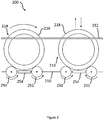
- a dishwashing machine 200 includes an apparatus for improving the cleaning of one or more items to be washed 214.
- the items to be washed are plates 216, 218.
- the apparatus includes a first rolling element 250 and a second rolling element 251.
- the first rolling element 250 and the second rolling element are incorporated into a rack 210 for holding the items to be washed 214.
- the rolling elements 250, 251 are spaced apart from one another to define a gap between them, which can (partially) accommodate an item to be washed when the item to be washed 214 is supported on the surface of the rolling elements 250, 251.
- the first rolling element 250 and the second rolling element 251 are each components that can be rotated about their longitudinal axis during a washing cycle so as to cause a movement of an item to be washed 214 that is resting on the surface of, and is in contact with, the rolling element 250, 251.
- each rolling element 250, 251 comprises a cylindrical shape. Other shapes are possible so long as the shape can be rotated to cause a movement of an item to be washed 214.
- the example shown in Figure 2 includes two pairs of rolling elements 250, 251.
- a single pair of rolling elements 250, 251 is provided.
- the apparatus includes more pairs of rolling elements 250, 251.
- both rolling elements 250 and 251 When the first rolling element 250 and the second rolling element 251 are rotated in the same direction, their rotation causes an item to be washed 214 that is supported on the surface of both rolling elements 250, 251 to also rotate (see Figure 3 ).
- Rotating both rolling elements in the same direction may, for example, mean rotating both rolling elements 250 and 251 clockwise, or rotating both rolling elements 250 and 251 anti-clockwise.
- both rolling elements 250 and 251 are rotated clockwise, this causes a corresponding anti-clockwise rotation of item to be washed 214 supported on the rolling elements.
- both rolling elements 250 and 251 When both rolling elements 250 and 251 are rotated anti-clockwise, this causes a corresponding clockwise rotation of item to be washed 214 supported on the rolling elements (see Figure 3 for example).
- first rolling element 250 and the second rolling element 251 are rotated in opposite directions (i.e. rotating one of the rolling elements in a clockwise direction and rotating the other rolling element in an anti-clockwise direction), towards one another, their rotation causes an item to be washed 214 that is supported on the surface of both rolling elements 250, 251 to be projected upwards and then fall down back downwards (see Figure 4 ).
- This type of movement may be referred to as “vibrational” or “reciprocating" movement of item to be washed 214.
- the item to be washed 214 is caused to move up and down vertically (or at least substantially vertically).
- first rolling element 250 and the second rolling element 251 are arranged such that the axis of rotation of the first rolling element 250 (i.e. its longitudinal axis) is parallel to the axis of rotation of the second rolling element 250 (i.e. its longitudinal axis). This arrangement helps to improve the stability of an item to be washed 214 when the item is on the surface of the rolling elements 250, 251 and when the rolling elements 250, 251 are rotating.
- the first rolling element 250 is the same size and shape as the second rolling element 251.
- the rolling elements 250, 251 both comprise a cylindrical shape and have a circular cross-section.
- both rolling elements 250, 251 have a same length and/or diameter.
- the rolling elements 250, 251 may be shaped and sized differently to the examples described above, and the rolling elements 250 and 251 may be shaped and sized differently to one another, so long as the shape and size is suitable for causing, when rotated, a movement of an item to be washed 214 that is in contact with an outer surface of the rolling elements 250, 251.
- each rolling element 250, 251 is supporting only one plate 216, 218.
- each rolling element 250, 251 may be constructed and arranged to support a plurality of plates 216, 218 and/or other items to be washed 214.
- the first rolling element 250 and the second rolling element 251 are both formed from a material that is relatively soft so that an item to be washed 214 is less likely to be damaged by the rolling elements 250, 251.
- the rolling elements 250, 251 are also formed from a "non-slip" material having a high friction surface so that each rolling element 250, 251 has a high degree of "grip" in order to more effectively cause an item to be washed 214 to move.
- the rolling elements 250, 251 may include an outer layer. The outer layer may be relatively soft and/or may be formed from a "non-slip" material.
- the dishwashing machine 200 may include one or more motors (not shown) for driving the rotation of the rolling elements 250, 251.
- the motors may be supplied with electrical power from a power connection 232. Activation of a motor begins rotation of a rolling element 250, 251. Deactivation of a motor ceases rotation of a rolling element 250, 251.
- the one or more motors are configured to rotate each rolling elements 250, 251 in either a clockwise direction or an anti-clockwise direction, as will be described.
- the dishwashing machine 200 may include one or more support elements for holding an item to be washed 214 (e.g. plate 218) in a substantially upright position whilst it is in contact with the first rolling element 250 and the second rolling element 251.
- a first support element 252 and a second support element 253 are provided. Maintaining an item to be washed 214 in an upright position during a washing cycle allows for the item 214 to be more thoroughly cleaned during the washing cycle and allows for water to more easily drain off of the item 214.
- the support elements 252 and 253 also prevent falling over of the item to be washed whilst being moved by the rolling elements 250 and 251.
- each support element 252, 253 comprises a rod that is formed from a waterproof material.
- the dishwashing machine 200 may include one or more distance adjustment elements 254 for adjusting a distance between the first rolling element 250 and the second rolling element 251. Adjusting a distance between the first and second rolling elements 250, 251 allows for the rolling elements 250, 251 to accommodate different sized plates 216, 218 or other items to be washed 214. If a distance between the rolling elements 250, 251 is increased then a larger item to be washed 214 can be accommodated. If a distance between the rolling elements 250, 251 is decreased then a smaller item to be washed 214 can be accommodated.
- the distance adjustment elements 254 are arranged to be manually adjustable by a user. In another example, the distance adjustment elements 254 are arranged to be adjustable by a motor.
- the controller 234 is configured to rotate the first rolling element 250 and the second rolling element 251 during a washing cycle so as to cause a movement of an item to be washed 214 that is in contact with the first rolling element 250 and the second rolling element 251.
- the controller 234 rotates the rolling elements 250, 251 in opposite directions to one another, towards the item to be washed 214, the item to be washed 214 is caused to be projected upwards (relative to the dishwashing machine 200 in normal use). Once the item to be washed 214 is free from the rolling elements 250, 251, it begins to drop back down (as is shown in Figure 4 ). When the item to be washed 214 is back in contact with the rolling elements 250, 251, it is again projected upwards.
- This type of movement may be referred to as "vibrational" movement or “reciprocating" movement.
- upwards it is meant that the item to be washed is moved vertical or substantially vertical. It will be understood that in some examples this upwards movement may be relatively small, for example 5 millimetres or less. This is sufficient movement in order to help with the washing process, and a small enough distance so as to not cause damage to the items being washed.
- Rotational and vibrational movement of an item to be washed 214 during a washing cycle improve the effectiveness of the washing cycle in removing dirt, food and other solids from the item to be washed.
- the controller 234 is configured to rotate the rolling elements 250, 251 in the same direction for a predetermined period of time during the washing cycle. In some examples, the controller 234 is also configured to rotate the rolling elements 250, 251 in opposite directions for a predetermined period of time during the washing cycle. The controller 234 may be configured to rotate the rolling elements 250, 251 in the same direction for a predetermined period of time and then rotate the rolling elements in opposite directions for a predetermined period of time, or vice versa and/or alternately. The controller 234 may be configured to rotate the rolling elements 250, 251 only during a particular phase of a washing cycle, such as during the cleaning phase.
- the controller 234 may be configured to activate one or more user selectable programs, sequences or patterns of rotating the rolling elements 250, 251. Each sequence includes, for a predetermined period of time, one or more of: rotating the rolling elements 250, 251 in the same direction, rotating the rolling elements 250, 251 in opposite directions and not rotating the rolling elements 250, 251.
- the programs may correspond with the dishwashing machine's user selectable washing cycles.
- the one or more user selectable programs or sequences may be stored as information on a data storage (not shown) included in the dishwashing machine 200, for example memory in the controller 234.
- a program may be selectable by a user using a user interface 236 and a display 238.
- the programs may be set by a user or they may be set by a manufacturer of the dishwashing machine 200.
- the dishwashing machine 200 is deactivated.
- a user wishes to wash one or more items to be washed 214 (in this example the plates 216, 218)
- the user opens the door 240 and place the plates 216, 218 into the washing compartment 204 such that the plates 216, 218 are in contact with the first rolling element 250 and the second rolling element 251.
- the plates are then supported in a substantially vertical orientation by the first and second support elements 252, 253.
- the plates 216, 218 are therefore put into the arrangement that is shown in Figure 2 .
- the user Before putting the plates 216, 218 into the washing compartment 204, the user first adjusts the distance adjustment elements 254 so that the space in between the rolling elements 250, 251 corresponds to the size of the plates 216, 218.
- the user then uses the user interface 236 and the display 238 to select a particular washing cycle and to activate the dishwashing machine 200.
- selecting a particular washing cycle also automatically selects a corresponding sequence of rotating the first and second rolling elements 250, 251.
- the controller 234 then causes the dishwashing machine 200 to operate according to the selected washing cycle and the corresponding sequence of rotating the rolling elements 250, 251.
- the selected washing cycle has three phases: a first wetting phase in which the plates 216, 218 are sprayed with hot water; a second cleaning phase in which the plates 216, 218 are sprayed with a mixture of hot water and a detergent; and a third rinsing/drying phase in which the plates 216, 218 are rinsed with clean hot water and then left to air dry in the hot washing compartment of the dishwashing machine 200.
- the controller 234 controls the operation of these phases.
- the controller 234 activates rotation of the rolling elements 250, 251 in a predetermined sequence during the washing cycle in order to improve the effectiveness of the cleaning of the plates 216, 218.
- the controller 234 in accordance with the predetermined sequence corresponding to the selected washing cycle, only rotates the rolling elements 250, 251 during the cleaning phase of the washing cycle.
- the rolling elements 250, 251 may be rotated during the other phases of the washing cycle.
- the first rolling element 250 and the second rolling element 251 are not rotated and thus remain stationary.
- the controller 234 alternates between rotating the first rolling element 250 and the second rolling element 251 in the same direction for a predetermined time period (e.g. 2 minutes) in order to cause rotational movement of the plates 216, 218, and rotating the first rolling element 250 and the second rolling element 251 in opposite directions, towards one another, for a predetermined time period (e.g. 2 minutes) in order to cause up and down movement of the plates 216, 218.
- the rolling elements 250, 251 move the plates 216, 218 whilst the washing mechanism is spraying them with hot water and detergent.
- Causing movement of items to be washed 214 during a washing cycle improves the quality of cleaning provided by the dishwashing machine 200. For example, by causing rotational movement, hot water and detergent sprayed during the washing cycle can reach all parts of the items to be washed 214. In addition, by causing vibrational up and down movement, dissolved solid waste is easily removed from the surface of the items to be washed 214.
- the controller 234 in this example ceases rotation of the first and second rolling elements 250, 251 so that they are again stationary during the rinsing/drying phase.
- the controller 234 alerts the user and deactivates the dishwashing machine 200.
- processor or processing system or circuitry referred to herein may in practice be provided by a single chip or integrated circuit or plural chips or integrated circuits, optionally provided as a chipset, an application-specific integrated circuit (ASIC), field-programmable gate array (FPGA), digital signal processor (DSP), graphics processing units (GPUs), etc.
- the chip or chips may comprise circuitry (as well as possibly firmware) for embodying at least one or more of a data processor or processors, a digital signal processor or processors, baseband circuitry and radio frequency circuitry, which are configurable so as to operate in accordance with the exemplary embodiments.
- the exemplary embodiments may be implemented at least in part by computer software stored in (non-transitory) memory and executable by the processor, or by hardware, or by a combination of tangibly stored software and hardware (and tangibly stored firmware).
- the invention also extends to computer programs, particularly computer programs on or in a carrier, adapted for putting the invention into practice.
- the program may be in the form of non-transitory source code, object code, a code intermediate source and object code such as in partially compiled form, or in any other non-transitory form suitable for use in the implementation of processes according to the invention.
- the carrier may be any entity or device capable of carrying the program.
- the carrier may comprise a storage medium, such as a solid-state drive (SSD) or other semiconductor-based RAM; a ROM, for example a CD ROM or a semiconductor ROM; a magnetic recording medium, for example a floppy disk or hard disk; optical memory devices in general; etc.
- SSD solid-state drive
- ROM read-only memory
- magnetic recording medium for example a floppy disk or hard disk
- optical memory devices in general etc.
Landscapes
- Washing And Drying Of Tableware (AREA)
- Transmission Devices (AREA)
Abstract
A dishwashing machine comprises: a controller (234); a first rolling element (250); and a second rolling element (251). The first rolling element (250) and the second rolling element (251) are spaced apart in a washing compartment of the dishwashing machine (200). The controller is configured to rotate the first rolling element (250) and the second rolling element (251) during a washing cycle so as to cause a movement of an item to be washed (214) that is in contact with the first rolling element (250) and the second rolling element (251).
Description
- The present disclosure relates to a dishwashing machine and a method of controlling a dishwashing machine.
- Dishwashing machines (also referred to as dishwashers) are used for washing items such as crockery and cutlery. A known dishwashing machine comprises a washing compartment for holding one or more items to be washed, and a washing mechanism for washing those items. Typically a user can select from a plurality of pre-defined washing cycles via a user interface on a front face of the dishwashing machine.
- According to a first aspect disclosed herein, there is provided a dishwashing machine comprising: a controller; a first rolling element; and a second rolling element, the first rolling element and the second rolling element being spaced apart in a washing compartment of the dishwashing machine; the controller being configured to rotate the first rolling element and the second rolling element during a washing cycle so as to cause a movement of an item to be washed that is in contact with the first rolling element and the second rolling element.
- Causing movement of an item to be washed during a washing cycle improves the quality of cleaning provided by the dishwashing machine. Such movement may allow hot water and detergent sprayed during a washing cycle to reach all parts of the items to be washed. In addition, the movements may allow for any dissolved solid waste to be easily removed from the surface of the items to be washed.
- In an example, the controller is configured to rotate the first rolling element and the second rolling element in a same direction so as to cause rotational movement of the item to be washed.
- In an example, the controller is configured to rotate the first rolling element and the second rolling element in the same direction for a predetermined period of time.
- In an example, the controller is configured to rotate the first rolling element and the second rolling element in opposite directions so as to cause up and down movement of the item to be washed.
- In an example, the controller is configured to rotate the first rolling element and the second rolling element in opposite directions for a predetermined period of time.
- In an example, the first and second rolling elements are arranged such that an axis of rotation of the first rolling element is parallel to an axis of rotation of the second rolling element.
- In an example, the dishwashing machine comprises a support element for propping up an item to be washed whilst the item to be washed is in contact with the first rolling element and the second rolling element.
- In an example, the first rolling element and the second rolling element are comprised in a rack for holding one or more items to be washed.
- In an example, the dishwashing machine comprises a distance adjustment element, the distance adjustment element being movable to change a distance between the first rolling element and the second rolling element so as to accommodate different sized items to be washed.
- In an example, the dishwashing machine comprises a plurality of pairs of first and second rolling elements.
- According to a second aspect disclosed herein, there is provided a method of controlling a dishwashing machine, the method comprising: rotating a first rolling element and a second rolling element during a washing cycle so as to cause a movement of an item to be washed that is in contact with the first rolling element and the second rolling element.
- In an example, the method comprises rotating the first rolling element and the second rolling element in a same direction so as to cause rotational movement of the item to be washed.
- In an example, the method comprises rotating the first rolling element and the second rolling element in a same direction for a predetermined period of time.
- In an example, the method comprises rotating the first rolling element and the second rolling element in opposite directions so as to cause up and down movement of the item to be washed.
- In an example, the method comprises rotating the first rolling element and the second rolling element in opposite directions for a predetermined period of time.
- To assist understanding of the present disclosure and to show how embodiments may be put into effect, reference is made by way of example to the accompanying drawings in which:
-
Figure 1 shows schematically a front view of an example of a dishwashing machine. -
Figure 2 shows schematically a front view of two pairs of a first rolling element and a second rolling element in contact with items to be washed. -
Figure 3 shows schematically an enlarged perspective view of a first rolling element and a second rolling element in contact with an item to be washed; and -
Figure 4 shows schematically an enlarged perspective view of a first rolling element and a second rolling element in contact with an item to be washed. - The present disclosure has applicability to dishwashing machines (also referred to as dishwashers). Dishwashing machines are used to automate the washing of items associated with food preparation and/or cooking and/or eating. Such items include crockery such as plates, bowls, cups, mugs etc. Such items may also include cutlery such as knives, forks, spoons, or indeed any other cooking or eating utensil. Other items that may be washed include glassware, food containers etc.
-
Figure 1 schematically shows an example of adishwashing machine 100. Thedishwashing machine 100 comprises amain body 102, within which there is awashing compartment 104. Thewashing compartment 104 comprises alower portion 106 and anupper portion 108. Thelower portion 106 comprises a tray orrack 110 for holding items to be washed, and theupper portion 108 comprises a tray orrack 112 for holding items to be washed. Theracks washing compartment 104 on roller assemblies. - Items to be washed are schematically shown at 114. In this case the items to be washed are schematically represented by
plates rack 112, andplates rack 120. Of course there may alternatively be any other type of item to be washed or combination of items to be washed. In the example ofFigure 1 awashing mechanism 123 comprisesspray arm 124 inlower portion 106, andspray arm 126 inupper portion 108. In other examples theupper spray arm 126 is omitted. Each spray arm comprises a series of holes or nozzles which can spray water upwardly towards the items to be washed 114, while thespray arms - The
dishwashing machine 100 further compriseswater inlet 128 andwater outlet 130 for enabling water to be fed to and taken away from the dishwashing machine respectively. In some examples a heater element (not shown) is provided for heating water as necessary. In other examples hot and cold water is drawn from a building's supply as required. A power connection is schematically shown at 132, which enables the dishwashing machine to be connected to mains electrical power for powering the dishwashing machine. - A controller is schematically shown at 134 for controlling operations of the dishwashing machine. The
controller 134 can, for example, cause the dishwashing machine to operate according to one or more pre-determined washing cycles selected via auser interface 136. The available washing cycles may differ from each other by temperature and/or duration, for example. Via the user interface 136 a user may also be able to select whether the washing cycle is for a full or half load. Adisplay 138 is also provided which can display information to the user. This may include information such as confirming a user's washing cycle selection, as well as information such as time remaining of a washing cycle that is in progress. - A door of the dishwashing machine is schematically shown at 140. The
door 140 is connected tomain body 120 viahinges Figure 1 the door is in an open position enabling access towashing compartment 104. Thedoor 140 may be moved to a closed position so that thewashing compartment 104 is then substantially enclosed. Thedoor 140 may also include a receptacle for holding dishwashing detergent (e.g. a dishwashing machine cube) which can be released in to the dishwashing machine during a wash. The receptacle for holding washing detergent may of course also be positioned elsewhere within the dishwashing machine. The dishwashing machine may also include one or more further receptacles for containing dishwashing machine salt and/or rinse aid, for example. - A washing cycle of a
dishwashing machine 100 includes three basic phases. First, the items to be washed 114 are wetted by thewashing mechanism 123. Next, the items to be washed 114 are cleaned by thewashing mechanism 123 spraying them with a mixture of hot water and a dishwashing detergent. Finally, the items to be washed 114 are rinsed with clean water and then air dried by the residual heat in the dishwashing machine or dried by a fan circulating hot air around thewashing compartment 104. - The present inventor has realised that, for example, the cleaning phase of the washing cycle of a
dishwashing machine 100 may result in low or sub-optimal quality cleaning of the items to be washed 114. - Referring to
Figures 2 ,3 and4 , adishwashing machine 200 includes an apparatus for improving the cleaning of one or more items to be washed 214. In this example, the items to be washed areplates first rolling element 250 and asecond rolling element 251. In this example, thefirst rolling element 250 and the second rolling element are incorporated into arack 210 for holding the items to be washed 214. The rollingelements elements - The
first rolling element 250 and thesecond rolling element 251 are each components that can be rotated about their longitudinal axis during a washing cycle so as to cause a movement of an item to be washed 214 that is resting on the surface of, and is in contact with, the rollingelement element - The example shown in
Figure 2 includes two pairs of rollingelements elements elements - When the
first rolling element 250 and thesecond rolling element 251 are rotated in the same direction, their rotation causes an item to be washed 214 that is supported on the surface of both rollingelements Figure 3 ). Rotating both rolling elements in the same direction may, for example, mean rotating both rollingelements elements elements elements Figure 3 for example). - When the
first rolling element 250 and thesecond rolling element 251 are rotated in opposite directions (i.e. rotating one of the rolling elements in a clockwise direction and rotating the other rolling element in an anti-clockwise direction), towards one another, their rotation causes an item to be washed 214 that is supported on the surface of both rollingelements Figure 4 ). This type of movement may be referred to as "vibrational" or "reciprocating" movement of item to be washed 214. For example the item to be washed 214 is caused to move up and down vertically (or at least substantially vertically). - In some examples, the
first rolling element 250 and thesecond rolling element 251 are arranged such that the axis of rotation of the first rolling element 250 (i.e. its longitudinal axis) is parallel to the axis of rotation of the second rolling element 250 (i.e. its longitudinal axis). This arrangement helps to improve the stability of an item to be washed 214 when the item is on the surface of the rollingelements elements - In some examples, the
first rolling element 250 is the same size and shape as thesecond rolling element 251. In the examples ofFigures 2 to 4 , the rollingelements elements elements elements elements Figures 3 and4 , each rollingelement plate element plates - In some examples, the
first rolling element 250 and thesecond rolling element 251 are both formed from a material that is relatively soft so that an item to be washed 214 is less likely to be damaged by the rollingelements elements element elements - The
dishwashing machine 200 may include one or more motors (not shown) for driving the rotation of the rollingelements element element rolling elements - The
dishwashing machine 200 may include one or more support elements for holding an item to be washed 214 (e.g. plate 218) in a substantially upright position whilst it is in contact with thefirst rolling element 250 and thesecond rolling element 251. In the example ofFigure 3 , afirst support element 252 and asecond support element 253 are provided. Maintaining an item to be washed 214 in an upright position during a washing cycle allows for theitem 214 to be more thoroughly cleaned during the washing cycle and allows for water to more easily drain off of theitem 214. Thesupport elements elements support element - As shown in
Figure 2 , thedishwashing machine 200 may include one or moredistance adjustment elements 254 for adjusting a distance between thefirst rolling element 250 and thesecond rolling element 251. Adjusting a distance between the first and secondrolling elements elements sized plates elements elements distance adjustment elements 254 are arranged to be manually adjustable by a user. In another example, thedistance adjustment elements 254 are arranged to be adjustable by a motor. - The controller 234, which comprises a processor or the like, is provided to control the operation of the rolling
elements first rolling element 250 and thesecond rolling element 251 during a washing cycle so as to cause a movement of an item to be washed 214 that is in contact with thefirst rolling element 250 and thesecond rolling element 251. - When the controller 234 rotates the rolling
elements Figure 3 ). - When the controller 234 rotates the rolling
elements dishwashing machine 200 in normal use). Once the item to be washed 214 is free from the rollingelements Figure 4 ). When the item to be washed 214 is back in contact with the rollingelements - Rotational and vibrational movement of an item to be washed 214 during a washing cycle improve the effectiveness of the washing cycle in removing dirt, food and other solids from the item to be washed.
- In some example the controller 234 is configured to rotate the rolling
elements elements elements elements - The controller 234 may be configured to activate one or more user selectable programs, sequences or patterns of rotating the rolling
elements elements elements elements dishwashing machine 200, for example memory in the controller 234. A program may be selectable by a user using a user interface 236 and a display 238. The programs may be set by a user or they may be set by a manufacturer of thedishwashing machine 200. - An example of use of the
dishwashing machine 200 shown inFigures 2 ,3 and4 will now be described. - Initially, the
dishwashing machine 200 is deactivated. When a user wishes to wash one or more items to be washed 214 (in this example theplates 216, 218), the user opens the door 240 and place theplates plates first rolling element 250 and thesecond rolling element 251. In this example the plates are then supported in a substantially vertical orientation by the first andsecond support elements plates Figure 2 . - Before putting the
plates distance adjustment elements 254 so that the space in between the rollingelements plates - The user then uses the user interface 236 and the display 238 to select a particular washing cycle and to activate the
dishwashing machine 200. In this example, selecting a particular washing cycle also automatically selects a corresponding sequence of rotating the first and secondrolling elements - The controller 234 then causes the
dishwashing machine 200 to operate according to the selected washing cycle and the corresponding sequence of rotating the rollingelements - In this example, the selected washing cycle has three phases: a first wetting phase in which the
plates plates plates dishwashing machine 200. As mentioned above, the controller 234 controls the operation of these phases. - The controller 234 activates rotation of the rolling
elements plates elements elements - In accordance with the predetermined sequence, during the wetting phase, the
first rolling element 250 and thesecond rolling element 251 are not rotated and thus remain stationary. - Next, during the cleaning phase of the washing cycle, the controller 234 alternates between rotating the
first rolling element 250 and thesecond rolling element 251 in the same direction for a predetermined time period (e.g. 2 minutes) in order to cause rotational movement of theplates first rolling element 250 and thesecond rolling element 251 in opposite directions, towards one another, for a predetermined time period (e.g. 2 minutes) in order to cause up and down movement of theplates elements plates - Causing movement of items to be washed 214 during a washing cycle improves the quality of cleaning provided by the
dishwashing machine 200. For example, by causing rotational movement, hot water and detergent sprayed during the washing cycle can reach all parts of the items to be washed 214. In addition, by causing vibrational up and down movement, dissolved solid waste is easily removed from the surface of the items to be washed 214. - Once the cleaning phase has finished, the controller 234 in this example ceases rotation of the first and second
rolling elements - After the user selected washing cycle has been completed, the controller 234 alerts the user and deactivates the
dishwashing machine 200. - Although the above described use case has been described in respect of
plates Figures 2 to 4 , it will be understood that this is by way of example and that the use case may equally be applied to the washing of any other one or more items to be washed. - It will be understood that the processor or processing system or circuitry referred to herein may in practice be provided by a single chip or integrated circuit or plural chips or integrated circuits, optionally provided as a chipset, an application-specific integrated circuit (ASIC), field-programmable gate array (FPGA), digital signal processor (DSP), graphics processing units (GPUs), etc. The chip or chips may comprise circuitry (as well as possibly firmware) for embodying at least one or more of a data processor or processors, a digital signal processor or processors, baseband circuitry and radio frequency circuitry, which are configurable so as to operate in accordance with the exemplary embodiments. In this regard, the exemplary embodiments may be implemented at least in part by computer software stored in (non-transitory) memory and executable by the processor, or by hardware, or by a combination of tangibly stored software and hardware (and tangibly stored firmware).
- Reference is made herein to data storage for storing data. This may be provided by a single device or by plural devices. Suitable devices include for example a hard disk and non-volatile semiconductor memory.
- Although at least some aspects of the embodiments described herein with reference to the drawings comprise computer processes performed in processing systems or processors, the invention also extends to computer programs, particularly computer programs on or in a carrier, adapted for putting the invention into practice. The program may be in the form of non-transitory source code, object code, a code intermediate source and object code such as in partially compiled form, or in any other non-transitory form suitable for use in the implementation of processes according to the invention. The carrier may be any entity or device capable of carrying the program. For example, the carrier may comprise a storage medium, such as a solid-state drive (SSD) or other semiconductor-based RAM; a ROM, for example a CD ROM or a semiconductor ROM; a magnetic recording medium, for example a floppy disk or hard disk; optical memory devices in general; etc.
- The examples described herein are to be understood as illustrative examples of embodiments of the invention. Further embodiments and examples are envisaged. Any feature described in relation to any one example or embodiment may be used alone or in combination with other features. In addition, any feature described in relation to any one example or embodiment may also be used in combination with one or more features of any other of the examples or embodiments, or any combination of any other of the examples or embodiments. Furthermore, equivalents and modifications not described herein may also be employed within the scope of the invention, which is defined in the claims.
Claims (15)
- A dishwashing machine comprising:a controller;a first rolling element; anda second rolling element, the first rolling element and the second rolling element being spaced apart in a washing compartment of the dishwashing machine;the controller being configured to rotate the first rolling element and the second rolling element during a washing cycle so as to cause a movement of an item to be washed that is in contact with the first rolling element and the second rolling element.
- A dishwashing machine according to claim 1, wherein the controller is configured to rotate the first rolling element and the second rolling element in a same direction so as to cause rotational movement of the item to be washed.
- A dishwashing machine according to claim 2, wherein the controller is configured to rotate the first rolling element and the second rolling element in the same direction for a predetermined period of time.
- A dishwashing machine according to any of claims 1 to 3, wherein the controller is configured to rotate the first rolling element and the second rolling element in opposite directions so as to cause up and down movement of the item to be washed.
- A dishwashing machine according to claim 4, wherein the controller is configured to rotate the first rolling element and the second rolling element in opposite directions for a predetermined period of time.
- A dishwashing machine according to any of claims 1 to 5 wherein the first and second rolling elements are arranged such that an axis of rotation of the first rolling element is parallel to an axis of rotation of the second rolling element.
- A dishwashing machine according to any of claims 1 to 6, comprising a support element for propping up an item to be washed whilst the item to be washed is in contact with the first rolling element and the second rolling element.
- A dishwashing machine according to any of claims 1 to 7, wherein the first rolling element and the second rolling element are comprised in a rack for holding one or more items to be washed.
- A dishwashing machine according to any of claims 1 to 8, comprising a distance adjustment element, the distance adjustment element being movable to change a distance between the first rolling element and the second rolling element so as to accommodate different sized items to be washed.
- A dishwashing machine according to any of claims 1 to 9, comprising a plurality of pairs of first and second rolling elements.
- A method of controlling a dishwashing machine, the method comprising:rotating a first rolling element and a second rolling element during a washing cycle so as to cause a movement of an item to be washed that is in contact with the first rolling element and the second rolling element.
- A method according to claim 11, comprising rotating the first rolling element and the second rolling element in a same direction so as to cause rotational movement of the item to be washed.
- A method according to claim 12, comprising rotating the first rolling element and the second rolling element in a same direction for a predetermined period of time.
- A method according to any of claims 11 to 13, comprising rotating the first rolling element and the second rolling element in opposite directions so as to cause up and down movement of the item to be washed.
- A method according to claim 14, comprising rotating the first rolling element and the second rolling element in opposite directions for a predetermined period of time.
Priority Applications (2)
| Application Number | Priority Date | Filing Date | Title |
|---|---|---|---|
| EP17208903.9A EP3501366A1 (en) | 2017-12-20 | 2017-12-20 | A dishwashing machine and method |
| TR2017/22799A TR201722799A2 (en) | 2017-12-20 | 2017-12-29 | A dishwashing machine and method. |
Applications Claiming Priority (1)
| Application Number | Priority Date | Filing Date | Title |
|---|---|---|---|
| EP17208903.9A EP3501366A1 (en) | 2017-12-20 | 2017-12-20 | A dishwashing machine and method |
Publications (1)
| Publication Number | Publication Date |
|---|---|
| EP3501366A1 true EP3501366A1 (en) | 2019-06-26 |
Family
ID=60702362
Family Applications (1)
| Application Number | Title | Priority Date | Filing Date |
|---|---|---|---|
| EP17208903.9A Withdrawn EP3501366A1 (en) | 2017-12-20 | 2017-12-20 | A dishwashing machine and method |
Country Status (2)
| Country | Link |
|---|---|
| EP (1) | EP3501366A1 (en) |
| TR (1) | TR201722799A2 (en) |
Citations (3)
| Publication number | Priority date | Publication date | Assignee | Title |
|---|---|---|---|---|
| US2095502A (en) * | 1931-03-06 | 1937-10-12 | Hobart Mfg Co | Cleaning and sterilizing method and apparatus |
| DE9212169U1 (en) * | 1992-09-09 | 1992-11-26 | Kao, Kuo-Kuen, Hsin-Chuan, Taipeh | Dishwasher conveyor |
| EP1671574A2 (en) * | 2004-12-16 | 2006-06-21 | Premark FEG L.L.C. | Dish carrier for dishwasher |
-
2017
- 2017-12-20 EP EP17208903.9A patent/EP3501366A1/en not_active Withdrawn
- 2017-12-29 TR TR2017/22799A patent/TR201722799A2/en unknown
Patent Citations (3)
| Publication number | Priority date | Publication date | Assignee | Title |
|---|---|---|---|---|
| US2095502A (en) * | 1931-03-06 | 1937-10-12 | Hobart Mfg Co | Cleaning and sterilizing method and apparatus |
| DE9212169U1 (en) * | 1992-09-09 | 1992-11-26 | Kao, Kuo-Kuen, Hsin-Chuan, Taipeh | Dishwasher conveyor |
| EP1671574A2 (en) * | 2004-12-16 | 2006-06-21 | Premark FEG L.L.C. | Dish carrier for dishwasher |
Also Published As
| Publication number | Publication date |
|---|---|
| TR201722799A2 (en) | 2019-07-22 |
Similar Documents
| Publication | Publication Date | Title |
|---|---|---|
| EP3498145A1 (en) | Spray arm assembly for dishwashing machine, dishwashing machine and control method thereof | |
| US8696827B2 (en) | Dishwasher with imaging device for measuring load characteristics and a method for controlling same | |
| ES2913491T3 (en) | Dishwasher in the form of a commercial utensil washer or dishwasher designed as a batch dishwasher | |
| EP3123918B1 (en) | Multi-sided, rotatable engagement elements for a dishwasher rack | |
| US5131419A (en) | Multi-function warewashing machine | |
| EP3536216B1 (en) | Dishwasher | |
| EP3488756B1 (en) | Dishwashing machine and method | |
| EP2600757B1 (en) | Dishwasher | |
| CN110730625B (en) | Method and device for cleaning and rinsing articles sensitive to temperature changes | |
| CN206372019U (en) | Basket and Dishwasher | |
| EP3505039B1 (en) | Dishwashing machine and method | |
| EP3434168A1 (en) | Dishwasher, method of operating a dishwasher, and computer program | |
| AU2020283797B2 (en) | Method for cleaning cutlery or cutlery parts, cutlery holder for holding cutlery to be cleaned in a dishwasher, and dishwasher | |
| US20230404361A1 (en) | Dishwasher with a rotating rack and two separated washing chamber and rinse chamber operating at same time | |
| EP3970594B1 (en) | Dishwashing machine | |
| JP2005110901A (en) | dishwasher | |
| EP3533374A1 (en) | Improved dishwashing arrangement and method | |
| EP3714756B1 (en) | Mounting bracket for a dishwasher | |
| EP3669741B1 (en) | Cleaning apparatus for a dishwasher | |
| CN112842215A (en) | Control method, processor and device for dish washing machine and dish washing machine | |
| WO2022184228A1 (en) | Dishwashing machine and method of operating a dishwashing machine | |
| EP3632290B1 (en) | A washing rack comprising a holder | |
| US11399693B2 (en) | Ergonomic intelligent dishwasher | |
| JP7564703B2 (en) | dishwasher | |
| US11944256B2 (en) | Easy loading silverware basket |
Legal Events
| Date | Code | Title | Description |
|---|---|---|---|
| PUAI | Public reference made under article 153(3) epc to a published international application that has entered the european phase |
Free format text: ORIGINAL CODE: 0009012 |
|
| AK | Designated contracting states |
Kind code of ref document: A1 Designated state(s): AL AT BE BG CH CY CZ DE DK EE ES FI FR GB GR HR HU IE IS IT LI LT LU LV MC MK MT NL NO PL PT RO RS SE SI SK SM TR |
|
| AX | Request for extension of the european patent |
Extension state: BA ME |
|
| STAA | Information on the status of an ep patent application or granted ep patent |
Free format text: STATUS: THE APPLICATION IS DEEMED TO BE WITHDRAWN |
|
| 18D | Application deemed to be withdrawn |
Effective date: 20200103 |