EP3501082B1 - System and method for integrating hybrid energy storage into direct current power systems - Google Patents
System and method for integrating hybrid energy storage into direct current power systems Download PDFInfo
- Publication number
- EP3501082B1 EP3501082B1 EP17797194.2A EP17797194A EP3501082B1 EP 3501082 B1 EP3501082 B1 EP 3501082B1 EP 17797194 A EP17797194 A EP 17797194A EP 3501082 B1 EP3501082 B1 EP 3501082B1
- Authority
- EP
- European Patent Office
- Prior art keywords
- coupled
- converter
- electrical
- voltage
- switching
- Prior art date
- Legal status (The legal status is an assumption and is not a legal conclusion. Google has not performed a legal analysis and makes no representation as to the accuracy of the status listed.)
- Active
Links
Images



Classifications
-
- H—ELECTRICITY
- H02—GENERATION; CONVERSION OR DISTRIBUTION OF ELECTRIC POWER
- H02J—ELECTRIC POWER NETWORKS; CIRCUIT ARRANGEMENTS OR SYSTEMS FOR SUPPLYING OR DISTRIBUTING ELECTRIC POWER; SYSTEMS FOR STORING ELECTRIC ENERGY
- H02J1/00—Circuit arrangements for DC mains or DC distribution networks
- H02J1/10—Parallel operation of DC sources
- H02J1/102—Parallel operation of DC sources being switching converters
-
- H—ELECTRICITY
- H02—GENERATION; CONVERSION OR DISTRIBUTION OF ELECTRIC POWER
- H02J—ELECTRIC POWER NETWORKS; CIRCUIT ARRANGEMENTS OR SYSTEMS FOR SUPPLYING OR DISTRIBUTING ELECTRIC POWER; SYSTEMS FOR STORING ELECTRIC ENERGY
- H02J1/00—Circuit arrangements for DC mains or DC distribution networks
- H02J1/10—Parallel operation of DC sources
-
- H—ELECTRICITY
- H02—GENERATION; CONVERSION OR DISTRIBUTION OF ELECTRIC POWER
- H02J—ELECTRIC POWER NETWORKS; CIRCUIT ARRANGEMENTS OR SYSTEMS FOR SUPPLYING OR DISTRIBUTING ELECTRIC POWER; SYSTEMS FOR STORING ELECTRIC ENERGY
- H02J7/00—Circuit arrangements for charging or discharging batteries or for supplying loads from batteries
- H02J7/34—Parallel operation in networks using both storage and other DC sources, e.g. providing buffering
- H02J7/345—Parallel operation in networks using both storage and other DC sources, e.g. providing buffering using capacitors as storage or buffering devices
-
- H—ELECTRICITY
- H02—GENERATION; CONVERSION OR DISTRIBUTION OF ELECTRIC POWER
- H02J—ELECTRIC POWER NETWORKS; CIRCUIT ARRANGEMENTS OR SYSTEMS FOR SUPPLYING OR DISTRIBUTING ELECTRIC POWER; SYSTEMS FOR STORING ELECTRIC ENERGY
- H02J9/00—Circuit arrangements for emergency or stand-by power supply, e.g. for emergency lighting
-
- H—ELECTRICITY
- H02—GENERATION; CONVERSION OR DISTRIBUTION OF ELECTRIC POWER
- H02M—APPARATUS FOR CONVERSION BETWEEN AC AND AC, BETWEEN AC AND DC, OR BETWEEN DC AND DC, AND FOR USE WITH MAINS OR SIMILAR POWER SUPPLY SYSTEMS; CONVERSION OF DC OR AC INPUT POWER INTO SURGE OUTPUT POWER; CONTROL OR REGULATION THEREOF
- H02M1/00—Details of apparatus for conversion
- H02M1/0067—Converter structures employing plural converter units, other than for parallel operation of the units on a single load
- H02M1/0077—Plural converter units whose outputs are connected in series
-
- H—ELECTRICITY
- H02—GENERATION; CONVERSION OR DISTRIBUTION OF ELECTRIC POWER
- H02M—APPARATUS FOR CONVERSION BETWEEN AC AND AC, BETWEEN AC AND DC, OR BETWEEN DC AND DC, AND FOR USE WITH MAINS OR SIMILAR POWER SUPPLY SYSTEMS; CONVERSION OF DC OR AC INPUT POWER INTO SURGE OUTPUT POWER; CONTROL OR REGULATION THEREOF
- H02M3/00—Conversion of DC power input into DC power output
- H02M3/22—Conversion of DC power input into DC power output with intermediate conversion into AC
- H02M3/24—Conversion of DC power input into DC power output with intermediate conversion into AC by static converters
- H02M3/28—Conversion of DC power input into DC power output with intermediate conversion into AC by static converters using discharge tubes with control electrode or semiconductor devices with control electrode to produce the intermediate AC
- H02M3/325—Conversion of DC power input into DC power output with intermediate conversion into AC by static converters using discharge tubes with control electrode or semiconductor devices with control electrode to produce the intermediate AC using devices of a triode or a transistor type requiring continuous application of a control signal
- H02M3/335—Conversion of DC power input into DC power output with intermediate conversion into AC by static converters using discharge tubes with control electrode or semiconductor devices with control electrode to produce the intermediate AC using devices of a triode or a transistor type requiring continuous application of a control signal using semiconductor devices only
- H02M3/33569—Conversion of DC power input into DC power output with intermediate conversion into AC by static converters using discharge tubes with control electrode or semiconductor devices with control electrode to produce the intermediate AC using devices of a triode or a transistor type requiring continuous application of a control signal using semiconductor devices only having several active switching elements
- H02M3/33576—Conversion of DC power input into DC power output with intermediate conversion into AC by static converters using discharge tubes with control electrode or semiconductor devices with control electrode to produce the intermediate AC using devices of a triode or a transistor type requiring continuous application of a control signal using semiconductor devices only having several active switching elements having at least one active switching element at the secondary side of an isolation transformer
-
- H—ELECTRICITY
- H02—GENERATION; CONVERSION OR DISTRIBUTION OF ELECTRIC POWER
- H02M—APPARATUS FOR CONVERSION BETWEEN AC AND AC, BETWEEN AC AND DC, OR BETWEEN DC AND DC, AND FOR USE WITH MAINS OR SIMILAR POWER SUPPLY SYSTEMS; CONVERSION OF DC OR AC INPUT POWER INTO SURGE OUTPUT POWER; CONTROL OR REGULATION THEREOF
- H02M7/00—Conversion of AC power input into DC power output; Conversion of DC power input into AC power output
- H02M7/42—Conversion of DC power input into AC power output without possibility of reversal
- H02M7/44—Conversion of DC power input into AC power output without possibility of reversal by static converters
- H02M7/48—Conversion of DC power input into AC power output without possibility of reversal by static converters using discharge tubes with control electrode or semiconductor devices with control electrode
- H02M7/483—Converters with outputs that each can have more than two voltages levels
- H02M7/4835—Converters with outputs that each can have more than two voltages levels comprising two or more cells, each including a switchable capacitor, the capacitors having a nominal charge voltage which corresponds to a given fraction of the input voltage, and the capacitors being selectively connected in series to determine the instantaneous output voltage
-
- H—ELECTRICITY
- H02—GENERATION; CONVERSION OR DISTRIBUTION OF ELECTRIC POWER
- H02J—ELECTRIC POWER NETWORKS; CIRCUIT ARRANGEMENTS OR SYSTEMS FOR SUPPLYING OR DISTRIBUTING ELECTRIC POWER; SYSTEMS FOR STORING ELECTRIC ENERGY
- H02J1/00—Circuit arrangements for DC mains or DC distribution networks
- H02J1/002—Circuit arrangements for DC mains or DC distribution networks using intermediate DC-AC-DC conversion
-
- H—ELECTRICITY
- H02—GENERATION; CONVERSION OR DISTRIBUTION OF ELECTRIC POWER
- H02J—ELECTRIC POWER NETWORKS; CIRCUIT ARRANGEMENTS OR SYSTEMS FOR SUPPLYING OR DISTRIBUTING ELECTRIC POWER; SYSTEMS FOR STORING ELECTRIC ENERGY
- H02J7/00—Circuit arrangements for charging or discharging batteries or for supplying loads from batteries
- H02J7/50—Circuit arrangements for charging or discharging batteries or for supplying loads from batteries acting upon multiple batteries simultaneously or sequentially
Definitions
- the field of the disclosure relates generally to electrical power conversion and electrical energy storage systems, and, more specifically, to systems and methods for integrating hybrid energy storage into direct current (DC) power systems.
- DC direct current
- ESDs energy storage devices
- AC bi-directional DC-to-alternating current
- non-modular topologies such as buck-boost converter architectures are limited in attainable switching frequencies and dynamic responsiveness, and also present challenges related to fault isolation and tolerance.
- electrical loads supported thereby require shutdown until system repairs are made, and such repairs are costly and time-consuming in at least some known systems and methods, and they may require a complete redesign and re-build of the power converter for affected load devices.
- US 2014/152109 discloses an uninterruptible power supplies realized with medium voltage converters comprising a first DC bus, a HF DC/DC converter, and an MMC converter used as a DC/AC converter connected in parallel to each other.
- US 2015/130420 discloses a MMC converter used as a DC/ DC converter with multiple energy storage devices, used as a rechargeable energy storage device.
- US 2009/091302 and US 2010/109344 disclose electrical energy storage systems that may provide temporary power to an electrical power distribution system, also known as UPS devices.
- US 2015/108091 and US 2016/056710 disclose electrical energy storage systems that may provide temporary power to an electrical power distribution system, also known as UPS devices.
- US 2014/091622 disclose a modular power conversion system for distributed power generation, storage and dispersed loads, and in particular to a modular power conversion system and power electronics which facilitates integration of the distributed power generation, storage and dispersed loads to a flexible smart grid, microgrid or microgrid clusters.
- a modular power converter system in one aspect, includes at least one electrical load device, and a modular power conversion device electrically coupled to the at least one electrical load device.
- the modular power conversion device includes at least one first-type ESD configured to induce a first DC voltage, and at least one APLM string coupled to the at least one first-type ESD.
- the at least one APLM string includes a plurality of APLMs coupled to each other.
- Each APLM of the plurality of APLMs has a plurality of switching devices including a first switching device and a second switching device coupled to each other in electrical series.
- Each APLM of the plurality of APLMs also has at least one second-type ESD coupled in electrical parallel with both of the first switching device and the second switching device.
- the at least one second-type ESD is configured to induce a second DC voltage.
- a method of operating a modular power converter system includes at least one first-type ESD configured to induce a first DC voltage, a plurality of APLMs coupled to the at least one first-type ESD, and at least one electrical load device coupled to the plurality of APLMs and coupled to the at least one first-type ESD.
- the method includes determining an average DC operating voltage of the at least one electrical load device, an average electrical power rating of the at least one electrical load device, and at least one additional electrical power rating greater than the average electrical power rating of the at least one electrical load device.
- the method also includes maintaining at least one second-type ESD coupled to each APLM of the plurality of APLMs at a second DC voltage.
- the method further includes supplying the at least one electrical load device with a first DC current at the first DC voltage substantially equal to the average DC voltage, where the first DC current provides a first amount of electrical power to the at least one electrical load device substantially equal to the average electrical power rating.
- the method also includes discharging, with a plurality of switching devices coupled to each APLM of the plurality of APLMs, the at least one second-type ESD to supply the at least one electrical load device with a second DC current at a voltage substantially equal to the first DC voltage, where the second DC current and the first DC current, when added together, provide a second amount of electrical power to the at least one electrical load device substantially equal to the at least one additional electrical power rating.
- Approximating language may be applied to modify any quantitative representation that could permissibly vary without resulting in a change in the basic function to which it is related. Accordingly, a value modified by a term or terms, such as “about”, “approximately”, and “substantially”, are not to be limited to the precise value specified. In at least some instances, the approximating language may correspond to the precision of an instrument for measuring the value.
- range limitations may be combined and/or interchanged, and such ranges are identified and include all the sub-ranges contained therein unless context or language indicates otherwise.
- processor and “computer” and related terms, e.g., “processing device”, “computing device”, and “controller” are not limited to just those integrated circuits referred to in the art as a computer, but broadly refers to a microcontroller, a microcomputer, a programmable logic controller (PLC), an application specific integrated circuit (ASIC), and other programmable circuits, and these terms are used interchangeably herein.
- memory may include, but is not limited to, a computer-readable medium, such as a random access memory (RAM), and a computer-readable non-volatile medium, such as flash memory.
- additional input channels may be, but are not limited to, computer peripherals associated with an operator interface such as a mouse and a keyboard.
- computer peripherals may also be used that may include, for example, but not be limited to, a scanner.
- additional output channels may include, but not be limited to, an operator interface monitor.
- the terms "software” and “firmware” are interchangeable, and include any computer program storage in memory for execution by personal computers, workstations, clients, and servers.
- the term "real-time” refers to at least one of the time of occurrence of the associated events, the time of measurement and collection of predetermined data, the time to process the data, and the time of a system response to the events and the environment. In the embodiments described herein, these activities and events occur substantially instantaneously.
- the systems and methods for integrating hybrid energy storage devices (ESDs) into DC power systems described herein enable functional integration of modular multi-level converter (MMC)-like power electronics into ESDs such as ultracapacitors for applications in a wide range of DC power system operating voltages.
- MMC modular multi-level converter
- the embodiments described herein also provide a modular, building block-based system which enables scalability and redundancy, and high efficiency and fault tolerant operation in both centralized and distributed power conversion applications.
- the embodiments described herein further facilitate use of simplified control schemes for energy and power management systems (EMS) based on current and power profiles of supported electrical loads.
- EMS energy and power management systems
- the systems and methods for integrating hybrid energy storage devices (ESDs) into DC power systems described herein also provide a high efficiency power converter having improved specific power density, less design and development time and expense, and reduced non-recurring engineering (NRE) and other operating costs relative to known systems.
- ESDs hybrid energy storage devices
- NRE non-recurring engineering
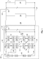
- FIG. 1 is a schematic diagram of an example of a modular power converter system 100.
- Modular power converter system includes a modular power conversion device 101.
- Modular power conversion device 101 includes at least one first-type ESD 102.
- Modular power conversion device 101 also includes a plurality of first-type ESDs 102 coupled to each other in electrical series as a first-type ESD string 104.
- a plurality of first-type ESDs 102 are coupled to each other in electrical parallel including, without limitation, as a plurality of first-type ESD strings 104.
- First-type ESD 102 induces a first direct current (DC) voltage, i.e., V 1 .
- DC direct current
- Modular power conversion device 101 also includes at least one active power link module (APLM) string 105.
- the APLM string 105 is embodied in a plurality of APLM strings 105 including a first APLM string 106 and a second APLM string 108 coupled in electrical parallel to both of first APLM string 106 and first-type ESD string 104.
- Each APLM string 105 of the plurality of APLM strings 105 includes a plurality of APLMs 110 coupled to each other in electrical series.
- At least one inductor 112 is coupled in electrical series to and between at least two APLMs 110 of the plurality of APLMs 110, with an equal number of APLMs 110 coupled to each of two terminals of inductor 112.
- First-type ESD string 104, APLM string 105, and at least one filter capacitor 114 are coupled in electrical parallel to a first DC bus 116. As such, first DC bus 116 and first-type ESD string 104, APLM string 105, and filter capacitor 114 are maintained at a voltage potential that is substantially equal to V 1 .
- APLM 110 includes at least one second-type ESD, not shown, configured to induce a second DC voltage, i.e., V 2 .
- First-type ESD 102 is embodied in a battery. In other example, not shown, first-type ESD 102 is embodied in at least one of an ultracapacitor, a film capacitor, an electrolytic capacitor, a fuel cell, and a rotating energy storage device (e.g., a flywheel).
- modular power converter system 100 includes a high-frequency (HF) DC-to-DC converter 118 coupled in electrical parallel to first DC bus 116 at a first side 120 of HF DC-to-DC converter 118.
- HF high-frequency
- a second DC bus 122 is also coupled to HF DC-to-DC converter 118 at a second side 124 thereof opposite first side 120.
- HF DC-to-DC converter 118 is configured to inductively couple and galvanically isolate first DC bus 116 and second DC bus 122.
- HF DC-to-DC converter 118 is further configured to convert V 1 to a third DC voltage, i.e., V 3 .
- second DC bus 122 is maintained at a voltage potential substantially equal to V 3 .
- at least one electrical load device 126 is coupled in electrical parallel to second DC bus 122. In other examples, not shown, a plurality of electrical load devices 126 are coupled in electrical series to second DC bus 122.
- a plurality of electrical load devices 126 are coupled in electrical parallel to second DC bus.
- modular power converter system 100 does not include HF DC-to-DC converter 118 and second DC bus 122.
- electrical load device 126 is coupled in electrical parallel and further galvanically coupled to modular power conversion device 101 through first DC bus 116 only, and therefore, APLM string 105, first-type ESD string 104, and electrical load devices are each maintained at a voltage potential substantially equal to V 1 .
- Modular power converter system 100 further includes a plurality of sensors coupled to a switching controller 128 that is further coupled to each APLM 110 of the at least two APLMs 110.
- a first sensor 130 is coupled to second DC bus 122 and is configured to detect and measure a load current, i.e., I L , through electrical load device 126 on second side 124.
- a second sensor 132 is coupled to first DC bus and is configured to detect and measure a first side current, i.e., I P , transmitted to HF DC-to-DC converter 118 from first side 120.
- a third sensor 134 is coupled to first-type ESD 102 and is configured to detect and measure a first-type ESD voltage, i.e., V 1 .
- switching controller 128 is configured to control the switching states (e.g., frequency and duty cycle of switching) of a plurality of switching devices in each APLM 110 of the at least two APLMs 110 and in HF DC-to-DC converter 118.
- each APLM 110 of the at least two APLMs 110 is detachably and electrically coupled to modular power converter system 100 such that, in the event of malfunction, a non-functional APLM 110 is removable and replaceable from APLM string 105 and modular power converter system 100.
- Modular power converter system 100 also includes at least one power source 136 coupled in electrical parallel to second DC bus 122.
- Power source 136 is configured to induce a DC voltage including, without limitation, a DC voltage substantially equal to V 3 , to supply electrical load device 126 with electric power required for operation.
- a DC voltage including, without limitation, a DC voltage substantially equal to V 3
- including power source 136 on second DC bus 122 facilitates continued operation of electrical load device 126 at V 3 in cases such as removal of modular power conversion device 101 from modular power converter system 100 for at least one of maintenance, reconfiguration, and replacement.
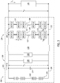
- FIG. 2 is a schematic diagram of an embodiment of a modular power converter system 200.
- a modular power conversion device 201 includes plurality of APLM strings 105 coupled in electrical parallel to second DC bus 122, rather than to first DC bus 116.
- Modular power conversion device 201 also includes HF DC-to-DC converter 118.
- at least one APLM string 105 is coupled in electrical parallel to both of first DC bus 116 and second DC bus 122.
- both of the plurality of APLM strings 105 and the at least one electrical load device 126 are maintained at V 3 on second side 124 of HF DC-to-DC converter 118, while the at least one first-type ESD 102 is maintained at V 1 on first side 120 of HF DC-to-DC converter 118.
- the plurality of APLM strings 105 are galvanically isolated and inductively coupled to first-type ESD 102.
- At least one electrical load device 126 is coupled in electrical parallel to first DC bus 116 in addition to being coupled in electrical parallel to second DC bus 122. At least one additional electrical load device 126 coupled to first DC bus 116 is thus configured to operate at a DC voltage potential substantially equal to V 1 .
- APLM string 105 on first side 120 is maintained at V 1
- APLM string 105 on second side 124 is maintained at V 3 .
- at least one first-type ESD string 104 is coupled in electrical parallel to second side 124 instead of, or in addition to, being coupled to first side 120.
- Modular power converter system 200 also includes at least one power source 136 coupled in electrical parallel to first DC bus 116, and is configured to induce a DC voltage including, without limitation, a DC voltage substantially equal to V 1 , to supply at least one additional electrical load device 126 coupled to first DC bus 116 with electric power required for operation.
- a DC voltage including, without limitation, a DC voltage substantially equal to V 1
- including power source 136 on first DC bus 116 facilitates continued operation of electrical load device 126 at V 1 in cases such as removal of first-type ESD string 104 from modular power converter system 200 for at least one of maintenance, reconfiguration, and replacement.
- first-type ESD string 104 a primary source of electrical power is embodied in first-type ESD string 104.
- first-type ESD string 104 a primary source of electrical power is embodied in first-type ESD string 104.
- power source 136 can include an alternating current-to-DC power converter which converts AC electrical power to a DC voltage on at least one of first DC bus 116 and second DC bus 122 from at least one of an alternating current (AC) generator and an AC utility grid.
- power source 136 can include renewable electric power resources such as a photovoltaic system coupled to at least one of first DC bus 116 and second DC bus 122.
- first-type ESD string 104 can be charged and maintained at a voltage potential of at least one of V 1 and V 3 through various type of power sources 136, and modular power converter systems 100 and 200 can utilize first-type ESD string 104 as a primary source of power, and employ such other aforementioned power sources 136 as a backup power source.
- first-type ESD string 104 can be maintained at a voltage potential of at least one of V 1 and V 3 , but modular power converter systems 100 and 200 can employ at least one power source 136 for primary power, and use first-type ESD string 104 as a backup source.
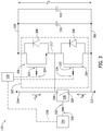
- FIG. 3 is a schematic diagram of an APLM 110 that may be used in modular power converter system 100 and modular power converter system 200 (shown in FIGs. 1 and 2 , respectively).
- the APLM 110 includes a plurality of switching devices 302.
- the plurality of switching devices 302 includes a first switching device 304 and a second switching device 306 coupled in electrical series with first switching device 304.
- Each switching device 302 of the plurality of switching devices 302 includes an antiparallel diode 308 coupled in electrical parallel thereto.
- APLM 110 includes at least one second-type ESD 310 coupled in electrical parallel with both of first switching device 304 and second switching device 306.
- Second-type ESD 310 induces second DC voltage, i.e., V 2 , across a first APLM terminal 312 and a second APLM terminal 314 of APLM 110.
- a capacitor 316 is coupled in electrical parallel with both of first switching device 304 and second switching device 306.
- second-type ESD 310 is embodied in an ultracapacitor.
- second-type ESD 310 is embodied in at least one of a battery, a film capacitor, an electrolytic capacitor, a rotating energy storage device, and a fuel cell.
- second-type ESD 310 is a different type of ESD (e.g., ultracapacitor) than first-type ESD 102 (e.g., battery).
- first-type ESD 102 is the same type of ESD as second-type ESD 310.
- first switching device 304 is coupled in electrical series to second switching device 306 at a first node 317.
- First node 317 includes second APLM terminal 314.
- First switching device 304 is further coupled to a second node 318 opposite first node 317 and second switching device 306 is further coupled to a third node 320 opposite first node 317.
- second-type ESD 310 and capacitor 316 are coupled to second node 318 and third node 320.
- each switching device 302 of the plurality of switching devices 302 is embodied in an insulated-gate bipolar transistor (IGBT).
- IGBT insulated-gate bipolar transistor
- each switching device 302 of the plurality of switching devices 302 is embodied in at least one of an integrated gate commutated thyristor, a non-linear controllable resistor, a varistor, and a transistor other than IGBT-type including, without limitation, a metal-oxide semiconductor field-effect transistor (MOSFET), an injection enhanced gate transistor, a junction gate field-effect transistor (JFET), a bipolar junction transistor (BJT), and combinations thereof.
- MOSFET metal-oxide semiconductor field-effect transistor
- JFET junction gate field-effect transistor
- BJT bipolar junction transistor
- These devices can be made of at least one of silicon (Si) and wide bandgap materials such as silicon carbide (SiC) or gallium nitride (GaN).
- each switching device 302 of the plurality of switching devices 302 includes a switch terminal 322 coupled to switching controller 128.
- Switching controller 128 is configured to transmit at least one switch control signal 324 to first switching device 304 and second switching device 306 to control their switching states including, without limitation, a frequency and a duty cycle of their switching.
- Switching controller 128 is further configured to transmit at least one switch control signal 324 to alternately open and close at least one switching device 302 of the plurality of switching devices 302.
- switching controller 128 enables modular power converter system 100 and modular power converter system 200 to establish a plurality of switching states of the plurality of switching devices 302 in APLM 110.
- switching controller 128 receives and transmits other control signals to and from other controllers located elsewhere within or outside at least one of APLM 110 and modular power converter systems 100 and 200.
- At least one bypass switch 326 including, without limitation, such devices as non-linear controllable resistors, varistors, and transistors such as IGBTs, MOSFETs, JFETs, BJTs, and relays, is coupled to APLM 110.
- Bypass switch 326 is coupled in electrical parallel with at least one switching device 302 of the plurality of switching devices 302 of APLM 110.
- Bypass switch 326 includes a first bypass terminal 328 coupled to second node 318 and a second bypass terminal 330 coupled to third node 320.
- Bypass switch 326 also includes a bypass control terminal 332 coupled to at least one bypass controller 334.
- Bypass controller 334 is configured to transmit a bypass control signal 336 to bypass control terminal 332 to close bypass switch 326 when at least one APLM state, including, without limitation, a physical state such as voltage, current, charge, and temperature associated with second-type ESD 310, is present.
- bypass controller 334 is configured to transmit bypass control signal 336 to bypass control terminal 332 to open bypass switch 326 when at least one APLM state is not present.
- an APLM string 105 current i.e., I M (also shown above with reference to FIGs. 1 and 2 ) flows through APLM 110 to second-type ESD 310 and the plurality of switching devices 302.
- bypass switch 326 When bypass switch 326 is closed, on the other hand, I M does not flow to second-type ESD 310 and the plurality of switching devices 302, i.e., I M is bypassed around APLM 110.
- Bypass controller 334 is at least one of electrically and communicatively coupled to switching controller 128.
- the plurality of switching devices 302 provide MMC-like power electronics integrated into each APLM 110 with second-type ESD 310.
- the flow of I M and the direction in which I M flows, i.e., I M versus -I M , in APLM string 105 is controlled via the timing of switching states of the plurality of switching devices 302, as implemented by switching controller 128.
- switching controller 128 facilitates maintaining a desired charging or discharging state of second-type ESD 310, and thereby the proportion of electrical power supplied to at least one of first DC bus 116 and second DC bus 122 by at least one APLM string 105.
- first switching device 304 on and second switching device 306 off enables current flow in the -I M direction and facilitates charging of second-type ESD 310.
- First switching device 304 off and second switching device 306 on enables current flow in the +I M direction, i.e., opposite the -I M direction, and facilitates discharging of second-type ESD 310 to support increased power requirements of electrical load device 126.
- switching controller 128 alternately opens and closes both of first switching device 304 and second switching device 306 at a predetermined frequency and duty cycle to maintain an efficient power and energy balance between first-type ESD 102, not shown, and second-type ESD 310, as further shown and described below with reference to FIGs. 6-10 .
- bypass controller 334 is configured to transmit bypass control signal 336 to close bypass switch 326 when the at least one APLM state has a first predetermined value, and open bypass switch 326 when the at least one APLM state has a second predetermined value different from the first predetermined value.
- At least one of bypass controller 334 and switching controller 128 is further configured to determine an operational status including a functional status and a non-functional status of at least one APLM 110 of the plurality of APLMs 110 in modular power conversion device 101.
- a physical state of APLM 110 such as an elevation of temperature of second-type ESD 310 above a predetermined threshold temperature is indicative of a non-functional status of APLM 110, whereas a temperature of second-type ESD 310 within a predetermined range of temperatures is indicative of a functional status of APLM 110.
- an operating voltage of second-type ESD 310 outside a predetermined tolerance of V 2 is indicative of a non-functional status of APLM 110, whereas the operating voltage of second-type ESD 310 within a predetermined tolerance of V 2 is indicative of a functional status of APLM 110.
- At least one of switching controller 128 and bypass controller 334 is, therefore, further configured to transmit a status signal 338, received at bypass controller 334, that is representative of the operational status of APLM 110.
- Bypass controller 334 thus transmits bypass control signal 336 to bypass switch 326 based on the operational status, and is further configured to alternately electrically couple (i.e., when bypass switch 326 is open) and electrically isolate (i.e., when bypass switch 326 is closed) at least one APLM 110 of APLM string(s) 105 from modular power converter system 100 and modular power converter system 200.
- APLM string 105 current (i.e., at least one of I M and -I M ) is permitted to flow through APLM(s) 110 having the functional status, and APLM string 105 current is not permitted to flow through APLM(s) 110 having the non-functional status, thereby providing inherent redundancy and continuity of operation in modular power converter systems 100 and 200 in the event of malfunction of at least one APLM 110, including, without limitation, a malfunction of at least one of second-type ESD 310 and at least one switching device 302 of the plurality of switching devices 302.
- switching of the plurality of switching devices 302 is interleaved.
- the MMC-like power electronics structure in each APLM 110 of the plurality of APLMs 110 in DC power systems applications results in a high equivalent switching frequency with relatively low switching frequency for each APLM 110 building block.
- the interleaved APLM string 105 will have an equivalent switching frequency of 12 ⁇ 4 kHz, i.e., 48 kHz. This high equivalent switching frequency enables a fast dynamic response with high power quality needed for many applications of modular power converter systems 100 and 200.
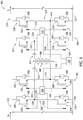
- FIG. 4 is a schematic diagram of an HF DC-to-DC converter 118 that may be used with the modular power converter system 100 and the modular power converter system 200 (shown in FIGs. 1 and 2 , respectively).
- First DC bus 116 and second DC bus 122 are coupled to first side 120 and second side 124, respectively, of HF DC-to-DC converter 118.
- HF DC-to-DC converter 118 includes at least one converter pair 401.
- Converter pair 401 is embodied in a plurality of converter pairs 401.
- Each converter pair 401 of the plurality of converter pairs 401 includes a DC-to-alternating current (AC) converter 402 coupled to first DC bus 116 and an AC-to-DC converter 404 coupled to second DC bus 122.
- AC AC-to-alternating current
- Each converter pair 401 also includes a primary winding 406 coupled to DC-to-AC converter 402 and a secondary winding 408 coupled to AC-to-DC converter 404.
- Primary winding 406 is defined by a first number of turns about a core 410
- secondary winding 408 is defined by a second number of turns about core 410, where the second number of turns is different from the first number of turns. In other examples, not shown, the first number of turns is equal to the second number of turns. In still other examples, not shown, converter pair 401 does not include core 410.
- primary winding 406 and secondary winding 408 are galvanically isolated from each other and are also inductively coupled to each other.
- Each DC-to-AC converter 402 of the plurality of converter pairs 401 is separately coupled in electrical parallel with first DC bus 116.
- Each AC-to-DC converter 404 of the plurality of converter pairs 401 is coupled to each other in electrical series as a string 409 of a plurality of AC-to-DC converters 404, and string 409 is further coupled in electrical parallel with second DC bus 122.
- HF DC-to-DC converter 118 is configured to step-up V 1 to V 3 (i.e., V 3 > Vi) through a transformer action of each converter pair 401 of the plurality of converter pairs 401.
- a step-up ratio i.e., V3 ⁇ V1 is determined by at least one of a ratio of first number of turns of primary winding 406 relative to second number of turns of secondary winding 408, and a switching frequency and duty cycle of a plurality of switching devices, not shown, in each of DC-to-AC converter 402 and AC-to-DC converter 404 (as shown and described below with reference to FIG. 5 ).
- HF DC-to-DC converter 118 is configured to at least one of step-down V 1 to V 3 (i.e., V 1 > V 3 ) and maintain V 1 substantially equal to V 3 .
- V 3 > V 1 I P flowing into DC-to-AC converter 402 on first DC bus 116 is greater than I L flowing out of AC-to-DC converter 404 on second DC bus 122, and an electrical power input on first side 120 is substantially equal to an electrical power output of second side 124.
- HF DC-to-DC converter 118 also facilitates isolation of electrical faults and malfunctions present on first side 120 and second side 124 from the above described components of modular power converter systems 100 and 200 on second side 124 and first side 120, respectively.
- HF DC-to-DC converter 118 utilizes converter pair 401 as a modular building block to facilitate replacing at least one malfunctioning converter pair 401 without replacing an entire HF DC-to-DC converter 118 subsystem. Modularity of converter pair 401 further enables customizing HF DC-to-DC converter 118 to fit the needs of a particular electrical power system application. Further, in operation, modular building blocks of converter pairs 401 enables HF DC-to-DC converter 118 to provide the fast response needed to meet transient response requirements for medium voltage loads on second side 124 of modular power converter systems 100 and 200.
- HF DC-to-DC converter 118 functions as a high frequency isolation transformer between first side 120 and second side 124.
- FIG. 5 is a converter pair 401 that may be used with HF DC-to-DC converter 118 (shown in FIG. 4 ).
- DC-to-AC converter 402 includes a first plurality of switching devices 502.
- First plurality of switching devices 502 is embodied in a first converter switching device 504 coupled in electrical series with a second converter switching device 506 at a first node 505, and a third converter switching device 508 coupled in electrical series with a fourth converter switching device 510 at a second node 511.
- Each switching device 502 of first plurality of switching devices 502 includes antiparallel diode 308 coupled in electrical parallel thereto.
- a first pair of switching devices 502 including first converter switching device 504 and second converter switching device 506 is coupled in electrical parallel to first DC bus 116.
- a second pair of switching devices 502 including third converter switching device 508 and fourth converter switching device 510 is also coupled in electrical parallel to first DC bus 116.
- first and second pairs of switching devices 502 form a full-bridge DC-to-AC power converter.
- Primary winding 406 is coupled to and between first node 505 and second node 511, and includes at least one first capacitor 512 coupled in electrical series therewith. In other embodiments, not shown, primary winding 406 does not include first capacitor 512.
- AC-to-DC converter 404 includes a second plurality of switching devices 514.
- Second plurality of switching devices 514 is embodied in a fifth converter switching device 516 coupled in electrical series with a sixth converter switching device 518 at a third node 519, and a seventh converter switching device 520 coupled in electrical series with an eighth converter switching device 522 at a fourth node 523.
- Each switching device 514 of second plurality of switching devices 514 includes antiparallel diode 308 coupled in electrical parallel thereto.
- a third pair of switching devices 514 including fifth converter switching device 516 and sixth converter switching device 518 is coupled in electrical parallel to second DC bus 122.
- a fourth pair of switching devices 514 including seventh converter switching device 520 and eighth converter switching device 522 is also coupled in electrical parallel to second DC bus 122.
- third and fourth pairs of switching devices 514 form a full-bridge DC-to-AC power converter.
- Secondary winding 408 is coupled to and between third node 519 and fourth node 523 and includes at least one second capacitor 524 coupled in electrical series therewith. In other examples, not shown, secondary winding 408 does not include second capacitor 524.
- each switching device 502 of first plurality of switching devices 502 includes a converter switch terminal 526 which is at least one of electrically coupled and communicatively coupled to a first converter controller 528.
- First converter controller 528 is configured to transmit at least one first converter control signal 530 to first plurality of switching devices 502 to control their switching states including, without limitation, a frequency and a duty cycle of their switching.
- First converter controller 528 is further configured to transmit at least one first converter control signal 530 to alternately open and close at least one switching device 502 of first plurality of switching devices 502.
- first converter controller 528 enables modular power converter systems 100 and 200 to establish a plurality of switching states of each switching device 502 of first plurality of switching devices 502 in DC-to-AC converter 402.
- First converter controller 528 is further coupled to switching controller 128.
- each switching device 514 of second plurality of switching devices 514 includes converter switch terminal 526 which is at least one of electrically coupled and communicatively coupled to a second converter controller 532.
- Second converter controller 532 is configured to transmit at least one second converter control signal 534 to second plurality of switching devices 514 to control their switching states including, without limitation, a frequency and a duty cycle of their switching.
- Second converter controller 532 is further configured to transmit at least one second converter control signal 534 to alternately open and close at least one switching device 514 of second plurality of switching devices 514.
- second converter controller 532 enables modular power converter systems 100 and 200 to establish a plurality of switching states of each switching device 514 of first plurality of switching devices 514 in AC-to-DC converter 404.
- Second converter controller 532 is further coupled to switching controller 128.
- converter pair 401 includes a single converter controller coupled to each switching device of both first plurality of switching devices 502 and second plurality of switching devices 514.
- the functionality of at least one of first converter controller 528 and second converter controller 532 is assumed by switching controller 128 coupled to each switching device of at least one of first plurality of switching devices 502 and second plurality of switching devices 514.
- primary winding 406 and second winding 408 inductively couples and galvanically isolates first plurality of switching devices 502 and second plurality of switching devices 514, respectively.
- First converter controller 528 and second converter controller 532 facilitate a high frequency switching of first plurality of switching devices 502 and second plurality of switching devices 514 to enable power conversion from first DC bus 116 to second DC bus 122 with negligible losses.
- at least one of first converter controller 528, second converter controller 532, and switching controller 128 transmits at least one of first 530 and second 534 converter control signals to alternately open and close each switching device of first plurality of switching devices 502 and second plurality of switching devices 514, respectively, to control their switching frequency and duty cycle.
- control of switching frequency and duty cycle of first plurality of switching devices 502 and second plurality of switching devices 514 dictates power conversion, i.e., V 3 ⁇ V 1 , of HF DC-to-DC converter 118.
- converter pair 401 of HF DC-to-DC converter 118 is a bi-directional power converter.
- a user of modular power converter systems 100 and 200 determines at least one of a switching timing, a switching frequency, and a switching duty cycle of first plurality of switching devices 502 and second plurality of switching devices 514 to facilitate desired power conversion parameters of HF DC-to-DC converter 118.
- users of modular power converter systems 100 and 200 configure, e.g., program a control logic of in at least one of the software and firmware of at least one of first converter controller 528, second converter controller 532, and switching controller 128 to facilitate efficient power and energy balance between first-type ESD 102 and second-type ESD 310, and to ensure adequate supply of electrical power to at least one electrical load device.
- electrical load device 126 is configured to both consume and supply electrical power
- flow of electrical power from first side 120 to second side 124 of HF DC-to-DC converter 118 is reversible to be used on first side 120 to charge at least one of first-type ESD 102 and second-type ESD 310.
- FIG. 6 is a graphical representation, i.e., graph 600, of operation of modular power converter system 100 and modular power converter system 200 (shown in FIGs. 1 and 2 , respectively).
- Graph 600 depicts a plurality of operating regions of modular power converter systems 100 and 200 based on an operating voltage (y-axis) of second-type ESD 310 in APLM 110 (e.g., ultracapacitor module voltage) over time in seconds (s) (x-axis).
- y-axis an operating voltage
- second-type ESD 310 in APLM 110 e.g., ultracapacitor module voltage
- At least one of switching controller 128, bypass controller 334, first converter controller 528, and second converter controller 532 are further configured to implement control (i.e., through controlling the plurality of switching states of switching devices in APLM 110 and HF DC-to-DC converter 118), and energy and power management of at least one of first-type ESD 102 and second-type ESD 310.
- APLM 110 is further embodied in a hybrid ESD (HESD) system that handles multiple time scale loads, supports stochastic pulse loads and transients including, without limitation, AC transients, and enables fuel-efficient generator operation and uninterrupted power supply (UPS) function.
- HESD hybrid ESD
- second-type ESD 310 embodied in at least one ultracapacitor
- the ultracapacitor handles short duration, i.e., seconds or fractions of seconds, pulse and transient loads, leveraging ultracapacitors' high power density and long cycle life.
- first-type ESD 102 is embodied in at least one battery, however, the battery facilitates longer time duration, i.e., minutes or hours, operation of electrical load device 126 and further supports fuel-efficient generator operation and UPS function.
- controls, and energy and power management of the HESD APLM 110 in the wider context of modular power converter systems 100 and 200 includes an EMS implemented, at least in part, by at least one of switching controller 128, bypass controller 334, first converter controller 528, and second converter controller 532 (as shown and described above with reference to FIGs. 1-5 ).
- EMS is embodied in at least one control algorithm based, at least in part, on at least one of filters, rules, and lookup tables.
- At least one additional electrical power rating e.g., a peak power rating P peak
- P peak is determined by users of modular power converter system 100 for electrical load device 126.
- the at least one additional electrical power rating is greater than P avg and represents an upper limit on electrical power that electrical load device 126 can be expected to experience (e.g., during load transients) during operation.
- Operation of modular power converter systems 100 and 200 includes a plurality of operating regions which depend upon operating conditions of electrical load device 126. Operating conditions of electrical load device 126 are determined by at least one sensor (as shown and described above with reference to FIG. 1 ). Based upon sensed parameters of at least one of electrical load device 126, first-type ESD 102, and second-type ESD 310, controllers in modular power converter systems 100 and 200 including, without limitation, switching controller 128, first converter controller 528, and second converter controller 532 establish a plurality of switching states in APLM 110 and HF DC-to-DC converter 118.
- the plurality of switching states enable alternate discharging and charging of second-type ESD 310, and also adjust the operating voltage, i.e., V 2 , of second-type ESD 310 to be a value that is within a plurality of predetermined ranges, as described below.
- modular power converter systems 100 and 200 operate in a first operating region 602 including an average power subregion 604.
- switching controller 128 and the plurality of switching devices 302 of APLM 110 maintain second-type ESD 310 embodied in at least one ultracapacitor at 235 V ⁇ V 2 ⁇ 265 V.
- Average power subregion 604 includes brief (e.g., at least one of seconds and fractions of a second in duration) positive and negative transients that do not require substantial deviations from P avg to support electrical load device 126.
- I L consists primarily of DC components and only partially of AC components.
- P avg is primarily supplied by first-type ESD 102 (e.g., at least one battery), and second-type ESD 310 in APLM 110 is discharged to supply transient power only where such requirements last for sustained periods of time (e.g., multiple seconds in length).
- first-type ESD 102 e.g., at least one battery
- second-type ESD 310 in APLM 110 is discharged to supply transient power only where such requirements last for sustained periods of time (e.g., multiple seconds in length).
- first operating region 602 also includes a first positive transient subregion 606 and a first negative transient subregion 608, i.e., a first and a second transition mode, respectively.
- First positive transient subregion 606 represents periods of time during which electrical load device 126 experiences primarily AC transient components and I L consists only partially of DC components.
- switching controller 128 and the plurality of switching devices 302 of APLM 110 maintain second-type ESD 310 at 225 V ⁇ V 2 ⁇ 235 V.
- first negative transient subregion 608 also represents periods of time during which electrical load device 126 experiences primarily AC transient components and I L consists only partially of DC components.
- AC transient components during first negative transient subregion 608 are negative load transients requiring electrical load device 126 to draw an amount of electrical power of less than P avg by as much as P peak - P avg .
- I P needed to be supplied from first side 120 for meeting electrical load device 126 power requirements decreases by an amount substantially equal to I M .
- switching controller 128 and the plurality of switching devices 302 of APLM 110 maintain second-type ESD 310 at 265 V ⁇ V 2 ⁇ 275 V. Therefore, APLM string 105 current flows in the ⁇ I M direction including, without limitation, to be used by at least one APLM 110 to charge at least one second-type ESD 310.
- the plurality of operating regions depicted in graph 600 includes a first AC transient mode region 610 and a second AC transient mode region 612.
- first AC transient mode region 610 electrical load device 126 experiences only AC transient components and power required by electrical load device 126 is supplied by both first-type ESD 102 and second-type ESD 310.
- first AC transient mode region 610 electrical power required by electrical load device 126 exceeds the amount of power required during first operating region 602, and I M flows from at least one APLM string 105 coupled to at least one of first side 120 and second side 124 from at least one second-type ESD 310 maintained at 275 V ⁇ V 2 ⁇ 282 V.
- second AC transient mode region 612 electrical power is supplied, at least in part, by electrical load device 126 and is thus available to charge second-type ESD 310 that is maintained at 187 V ⁇ V 2 ⁇ 225 V with APLM string 105 experiencing a net flow of APLM string 105 current in the ⁇ I M direction.
- the plurality of operating regions depicted in graph 600 includes a positive current only region 614 and a negative current only region 616.
- positive current only region 614 electrical power required by electrical load device 126 is supplied exclusively by second-type ESD 310 through discharging thereof.
- second-type ESD 310 is maintained at V 2 > 282 V.
- negative current only region 616 electrical load device 126 no longer draws electrical power from first-type ESD 102 and second-type ESD 310, but rather at least one of electrical load device 126 and power source 136 supplies electrical power to second-type ESD 310 where it is used to charge second-type ESD 310.
- second-type ESD 310 is maintained at V 2 ⁇ 225 V.
- the plurality of operating regions depicted in graph 600 represents an exemplary set the rules developed and implemented in defining and determining the control modes for the plurality of APLMs 110 (i.e., AC transient, DC, mixed AC transient and DC modes, and transition modes) based on V 2 and V 1 in modular power converter systems 100 and 200.
- FIG. 7 is a graphical representation, i.e., graph 700, of operation in an AC transient and DC mode of modular power converter system 100 and modular power converter system 200 (shown in FIGs. 1 and 2 , respectively).
- Graph 700 depicts APLM 110 mode of operations as a function of I L current frequency (Hz, x-axis) and power profile (y-axis).
- EMS control schemes for modular power converter systems 100 and 200 utilize sensors 130 and 134, switching devices 302, 502, and 514, switching, switching controller 128, and converter controllers 528 and 532 to facilitate APLM 110 usage for balanced energy and power support for both AC transients and DC load components.
- Graph 700 thus depicts operation in the first operating region 602 (as shown and described above with reference to FIG. 6 ).
- first-type ESD 102 As frequency of AC transient components of I L increases, the amount of power provided to electrical load device 126 by first-type ESD 102 relative to second-type ESD 310 decreases rapidly after 100 Hz. When the frequency of the AC transient components approaches 10 kHz, first-type ESD 102 provides little to no power to support electrical load device 126.
- FIG. 8 is a graphical representation, i.e., graph 800, of operation in an AC transient mode of modular power converter system 100 and modular power converter system 200 (shown in FIGs. 1 and 2 , respectively).
- Graph 800 depicts APLM 110 mode of operations as a function of I L current frequency (Hz, x-axis) and power profile (y-axis) in the first AC transient mode region 610.
- the proportion of electrical power supplied to electrical load device 126 by second-type ESD 310 rises rapidly after AC transient components reach a frequency of about 0.03 Hz, and between 0.03 Hz and 100 Hz, second-type ESD 310 predominantly supplies electrical power to electrical load device 126. After a frequency of 100 Hz, however, electrical power supplied by second-type ESD 310 declines until it supplies substantially no power after about 3000 Hz.
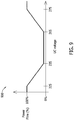
- FIG. 9 is a graphical representation, i.e., graph 900, of operation of modular power converter system 100 and modular converter system 200 (shown in FIGs. 1 and 2 , respectively).
- Graph 900 depicts power flow percentage (%), y-axis) from second-type ESD 310 I M current versus ultracapacitor voltage (i.e., V 2 , x-axis) in modular power converter systems 100 and 200.
- second-type ESD 310 With second-type ESD 310 maintained at an ultracapacitor voltage (i.e., V 2 , x-axis) between 235 V and 265 V, electrical load device 126 operates in the first operating region 602 and draws P avg primarily from first-type ESD 102 (as shown and described above with reference to FIG. 6 ). For V 2 ⁇ 235 V and V 2 > 265 V, power flow to and from second-type ESD 310 ramps up gradually until representing the full amount of power flow in modular power converter systems 100 and 200 for V 2 ⁇ 225 V and V 2 > 275 V, respectively.
- V 2 ⁇ 235 V and V 2 > 265 V power flow to and from second-type ESD 310 ramps up gradually until representing the full amount of power flow in modular power converter systems 100 and 200 for V 2 ⁇ 225 V and V 2 > 275 V, respectively.
- the EMS control scheme enables balanced utilization of APLM 110 and second-type ESD 310 to for efficient and proportional use of energy and power stored in first-type ESD 102 and second-type ESD 310 depending upon the power requirement of electrical load device 126 at any given instant in time. Efficient power and energy balance amongst the plurality of ESDs facilitates support of AC transients and DC components of electrical load device 126.
- a transition control scheme for battery current and power flow as a function of ultracapacitor voltage is depicted in graph 900.
- the transition control scheme depicted by graph 900 thus employs filter- and rule-based EMS algorithms that are straightforward and effective for implementation of a controls framework to lengthen battery life while reducing cost, size, and volume of the battery and overall energy storage system.
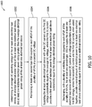
- FIG. 10 is a flowchart diagram of a method 1000 of operating modular power converter system 100 and modular power converter system 200.
- the 1000 includes determining 1002 an average DC operating voltage of electrical load device 126, an average electrical power rating of electrical load device 126, and at least one additional electrical power rating greater than the average electrical power rating of electrical load device 126.
- Method 1000 also includes maintaining 1004 second-type ESD 310 coupled to each APLM 110 of the plurality of APLMs 110 (i.e., of APLM string(s) 105) at V 2 .
- Method 1000 further includes supplying 1006 electrical load device 126 with a first DC current, i.e., I L , at V 1 substantially equal to the average DC voltage, where the first DC current provides a first amount of electrical power to electrical load device 126 substantially equal to the average electrical power rating.
- a first DC current i.e., I L
- Method 1000 also includes discharging 1008, with the plurality of switching devices 302 coupled to each APLM 110 of the plurality of APLMs 110, the second-type ESD 310 to supply electrical load device 126 with a second DC current, i.e., I M , at a voltage substantially equal to V 1 , where the second DC current and the first DC current, i.e., I M + I L , when added together, provide a second amount of electrical power electrical load device 126 substantially equal to the at least one additional electrical power rating.
- a second DC current i.e., I M
- the above-described systems and methods for integrating hybrid ESDs into DC power systems enable functional integration of MMC-like power electronics into ESDs such as ultracapacitors for applications in a wide range of DC power system operating voltages.
- the above-described examples and embodiments also provide a modular, building block-based system which enables scalability and redundancy, and high efficiency and fault tolerant operation in both centralized and distributed power conversion applications.
- the above-described examples and embodiments further facilitate use of simplified control schemes for EMS based on current and power profiles of supported electrical loads.
- the above-described systems and methods for integrating hybrid ESDs into DC power systems also provide a high efficiency power converter having improved specific power density, less design and development time and expense, and reduced NRE and other operating costs relative to known systems.
- An exemplary technical effect of the above-described systems and methods for integrating hybrid ESDs into DC power systems includes at least one of the following: (a) enabling functional integration of MMC-like power electronics into ESDs such as ultracapacitors for applications in a wide range of DC power system operating voltages; (b) providing a modular, building block-based system enabling scalability and redundancy, and high efficiency and fault tolerant operation in both centralized and distributed power conversion applications; (c) facilitating use of simplified control schemes for EMS based on current and power profiles of supported electrical loads; and (d) providing a high efficiency power converter having improved specific power density, less design and development time and expense, and reduced NRE and other operating costs relative to known systems.
- Examples of systems and methods for integrating hybrid ESDs into DC power systems, and methods of operating such systems and devices are not limited to the specific embodiments described herein, but rather, components of systems and/or steps of the methods may be utilized independently and separately from other components and/or steps described herein.
- the systems may also be used in combination with other systems requiring modularity, scalability, and redundancy, and the associated methods, and are not limited to practice with only the systems and methods for integrating hybrid ESDs into DC power systems as described herein.
- the example can be implemented and utilized in connection with many other power systems applications that are currently configured to provide high efficiency DC power conversion, e.g., and without limitation, power systems in renewable energy generation facilities.
- Such devices typically include a processor, processing device, or controller, such as a general purpose central processing unit (CPU), a graphics processing unit (GPU), a microcontroller, a reduced instruction set computer (RISC) processor, an application specific integrated circuit (ASIC), a programmable logic circuit (PLC), a field programmable gate array (FPGA), a digital signal processing (DSP) device, and/or any other circuit or processing device capable of executing the functions described herein.
- the methods described herein may be encoded as executable instructions embodied in a computer-readable medium, including, without limitation, a storage device and/or a memory device. Such instructions, when executed by a processing device, cause the processing device to perform at least a portion of the methods described herein.
- the above examples are exemplary only, and thus are not intended to limit in any way the definition and/or meaning of the term processor and processing device.
Landscapes
- Engineering & Computer Science (AREA)
- Power Engineering (AREA)
- Business, Economics & Management (AREA)
- Emergency Management (AREA)
- Dc-Dc Converters (AREA)
- Charge And Discharge Circuits For Batteries Or The Like (AREA)
Description
- This invention was made with Government support under contract number N00014-14-C-0103 awarded by the United States Office of Naval Research. The Government may have certain rights in this invention.
- The field of the disclosure relates generally to electrical power conversion and electrical energy storage systems, and, more specifically, to systems and methods for integrating hybrid energy storage into direct current (DC) power systems.
- In at least some known systems and methods for integrating energy storage devices (ESDs) into DC power systems, ESDs such as ultracapacitors positioned in current paths of bi-directional DC-to-alternating current (AC) converters experience undesirable AC ripple currents which degrade ESDs' performance, longevity, and power quality. To increase efficiency of power conversion where ESDs are exposed to AC currents in such known systems and methods, ESDs are over-sized to manage heat, which increases size, weight, and cost in addition to lowering specific power density.
- Also, in at least some known systems and methods for integrating ESDs into DC power systems, non-modular topologies such as buck-boost converter architectures are limited in attainable switching frequencies and dynamic responsiveness, and also present challenges related to fault isolation and tolerance. In the event of a fault in such "centralized" power conversion systems and methods, electrical loads supported thereby require shutdown until system repairs are made, and such repairs are costly and time-consuming in at least some known systems and methods, and they may require a complete redesign and re-build of the power converter for affected load devices.
-
US 2014/152109 discloses an uninterruptible power supplies realized with medium voltage converters comprising a first DC bus, a HF DC/DC converter, and an MMC converter used as a DC/AC converter connected in parallel to each other.US 2015/130420 discloses a MMC converter used as a DC/ DC converter with multiple energy storage devices, used as a rechargeable energy storage device.US 2009/091302 andUS 2010/109344 disclose electrical energy storage systems that may provide temporary power to an electrical power distribution system, also known as UPS devices. -
US 2015/108091 andUS 2016/056710 disclose electrical energy storage systems that may provide temporary power to an electrical power distribution system, also known as UPS devices.US 2014/091622 disclose a modular power conversion system for distributed power generation, storage and dispersed loads, and in particular to a modular power conversion system and power electronics which facilitates integration of the distributed power generation, storage and dispersed loads to a flexible smart grid, microgrid or microgrid clusters. - The invention is defined by the
independent claims 1 and 11. Preferred embodiments are described by the dependent claims. All the technical features of the independent claims are mandatory and not optional, irrespective of any statements to the contrary in the following passages. - In one aspect, a modular power converter system is provided. The modular power converter system includes at least one electrical load device, and a modular power conversion device electrically coupled to the at least one electrical load device. The modular power conversion device includes at least one first-type ESD configured to induce a first DC voltage, and at least one APLM string coupled to the at least one first-type ESD. The at least one APLM string includes a plurality of APLMs coupled to each other. Each APLM of the plurality of APLMs has a plurality of switching devices including a first switching device and a second switching device coupled to each other in electrical series. Each APLM of the plurality of APLMs also has at least one second-type ESD coupled in electrical parallel with both of the first switching device and the second switching device. The at least one second-type ESD is configured to induce a second DC voltage.
- In yet another aspect, a method of operating a modular power converter system is provided. The modular power converter system includes at least one first-type ESD configured to induce a first DC voltage, a plurality of APLMs coupled to the at least one first-type ESD, and at least one electrical load device coupled to the plurality of APLMs and coupled to the at least one first-type ESD. The method includes determining an average DC operating voltage of the at least one electrical load device, an average electrical power rating of the at least one electrical load device, and at least one additional electrical power rating greater than the average electrical power rating of the at least one electrical load device. The method also includes maintaining at least one second-type ESD coupled to each APLM of the plurality of APLMs at a second DC voltage. The method further includes supplying the at least one electrical load device with a first DC current at the first DC voltage substantially equal to the average DC voltage, where the first DC current provides a first amount of electrical power to the at least one electrical load device substantially equal to the average electrical power rating. The method also includes discharging, with a plurality of switching devices coupled to each APLM of the plurality of APLMs, the at least one second-type ESD to supply the at least one electrical load device with a second DC current at a voltage substantially equal to the first DC voltage, where the second DC current and the first DC current, when added together, provide a second amount of electrical power to the at least one electrical load device substantially equal to the at least one additional electrical power rating.
- These and other features, aspects, and advantages of the present disclosure will become better understood when the following detailed description is read with reference to the accompanying drawings in which like characters represent like parts throughout the drawings, wherein:
- FIG. is a schematic diagram of an example of a modular power converter system;
-
FIG. 2 is a schematic diagram of an embodiment of a modular power converter system; -
FIG. 3 is a schematic diagram of an active power link module (APLM) that may be used in the modular power converter systems shown inFIGs. 1 and2 ; -
FIG. 4 is a schematic diagram of an exemplary high frequency (HF) direct current (DC)-to-DC converter that may be used with the modular power converter systems shown inFIGs. 1 and2 ; -
FIG. 5 is a converter pair that may be used with the HF DC-to-DC converter shown inFIG. 4 ; -
FIG. 6 is a graphical representation of operation of the modular power converter systems shown inFIGs. 1 and2 ; -
FIG. 7 is a graphical representation of operation in an alternating current (AC) transient and DC mode of the modular power converter systems shown inFIGs. 1 and2 ; -
FIG. 8 is a graphical representation of operation in an AC transient mode of the modular power converter systems shown inFIGs. 1 and2 ; -
FIG. 9 is a graphical representation of operation of the modular power converter systems shown inFIGs. 1 and2 ; and -
FIG. 10 is a flowchart diagram of a method of operating a modular power converter system that may be used with the modular power converter systems shown inFIGs. 1 and2 . - Unless otherwise indicated, the drawings provided herein are meant to illustrate features of this disclosure. These features are believed to be applicable in a wide variety of systems comprising one or more embodiments of this disclosure. As such, the drawings are not meant to include all conventional features known by those of ordinary skill in the art to be required for the practice of the embodiments disclosed herein.
- In the following description the term "embodiment" may have been used for subject-matter that is not part of the invention as defined by the appended claims. Only those examples that comprise all the features of the independent claims are part of the invention and thus embodiments of the invention. Parts of the subject-matter of the description not covered by the claims constitutes background art or examples useful for understanding the invention. In the following specification and the claims, reference will be made to a number of terms, which shall be defined to have the following meanings.
- The singular forms "a", "an", and "the" include plural references unless the context clearly dictates otherwise.
- "Optional" or "optionally" means that the subsequently described event or circumstance may or may not occur, and that the description includes instances where the event occurs and instances where it does not.
- Approximating language, as used herein throughout the specification and claims, may be applied to modify any quantitative representation that could permissibly vary without resulting in a change in the basic function to which it is related. Accordingly, a value modified by a term or terms, such as "about", "approximately", and "substantially", are not to be limited to the precise value specified. In at least some instances, the approximating language may correspond to the precision of an instrument for measuring the value. Here and throughout the specification and claims, range limitations may be combined and/or interchanged, and such ranges are identified and include all the sub-ranges contained therein unless context or language indicates otherwise.
- As used herein, the terms "processor" and "computer" and related terms, e.g., "processing device", "computing device", and "controller" are not limited to just those integrated circuits referred to in the art as a computer, but broadly refers to a microcontroller, a microcomputer, a programmable logic controller (PLC), an application specific integrated circuit (ASIC), and other programmable circuits, and these terms are used interchangeably herein. In the embodiments described herein, memory may include, but is not limited to, a computer-readable medium, such as a random access memory (RAM), and a computer-readable non-volatile medium, such as flash memory. Alternatively, a floppy disk, a compact disc - read only memory (CD-ROM), a magneto-optical disk (MOD), and/or a digital versatile disc (DVD) may also be used. Also, in the embodiments described herein, additional input channels may be, but are not limited to, computer peripherals associated with an operator interface such as a mouse and a keyboard. Alternatively, other computer peripherals may also be used that may include, for example, but not be limited to, a scanner. Furthermore, in the exemplary embodiment, additional output channels may include, but not be limited to, an operator interface monitor.
- Further, as used herein, the terms "software" and "firmware" are interchangeable, and include any computer program storage in memory for execution by personal computers, workstations, clients, and servers.
- Furthermore, as used herein, the term "real-time" refers to at least one of the time of occurrence of the associated events, the time of measurement and collection of predetermined data, the time to process the data, and the time of a system response to the events and the environment. In the embodiments described herein, these activities and events occur substantially instantaneously.
- The systems and methods for integrating hybrid energy storage devices (ESDs) into DC power systems described herein enable functional integration of modular multi-level converter (MMC)-like power electronics into ESDs such as ultracapacitors for applications in a wide range of DC power system operating voltages. The embodiments described herein also provide a modular, building block-based system which enables scalability and redundancy, and high efficiency and fault tolerant operation in both centralized and distributed power conversion applications. The embodiments described herein further facilitate use of simplified control schemes for energy and power management systems (EMS) based on current and power profiles of supported electrical loads. The systems and methods for integrating hybrid energy storage devices (ESDs) into DC power systems described herein also provide a high efficiency power converter having improved specific power density, less design and development time and expense, and reduced non-recurring engineering (NRE) and other operating costs relative to known systems.
-
FIG. 1 is a schematic diagram of an example of a modularpower converter system 100. Modular power converter system includes a modularpower conversion device 101. Modularpower conversion device 101 includes at least one first-type ESD 102. Modularpower conversion device 101 also includes a plurality of first-type ESDs 102 coupled to each other in electrical series as a first-type ESD string 104. In other examples, not shown, a plurality of first-type ESDs 102 are coupled to each other in electrical parallel including, without limitation, as a plurality of first-type ESD strings 104. First-type ESD 102 induces a first direct current (DC) voltage, i.e., V1. - Modular
power conversion device 101 also includes at least one active power link module (APLM)string 105. TheAPLM string 105 is embodied in a plurality of APLM strings 105 including afirst APLM string 106 and asecond APLM string 108 coupled in electrical parallel to both offirst APLM string 106 and first-type ESD string 104. EachAPLM string 105 of the plurality of APLM strings 105 includes a plurality ofAPLMs 110 coupled to each other in electrical series. At least oneinductor 112 is coupled in electrical series to and between at least twoAPLMs 110 of the plurality ofAPLMs 110, with an equal number ofAPLMs 110 coupled to each of two terminals ofinductor 112. First-type ESD string 104,APLM string 105, and at least onefilter capacitor 114 are coupled in electrical parallel to afirst DC bus 116. As such,first DC bus 116 and first-type ESD string 104,APLM string 105, andfilter capacitor 114 are maintained at a voltage potential that is substantially equal to V1. - Also,
APLM 110 includes at least one second-type ESD, not shown, configured to induce a second DC voltage, i.e., V2. First-type ESD 102 is embodied in a battery. In other example, not shown, first-type ESD 102 is embodied in at least one of an ultracapacitor, a film capacitor, an electrolytic capacitor, a fuel cell, and a rotating energy storage device (e.g., a flywheel). Furthermore, modularpower converter system 100 includes a high-frequency (HF) DC-to-DC converter 118 coupled in electrical parallel tofirst DC bus 116 at afirst side 120 of HF DC-to-DC converter 118. Asecond DC bus 122 is also coupled to HF DC-to-DC converter 118 at asecond side 124 thereof oppositefirst side 120. HF DC-to-DC converter 118 is configured to inductively couple and galvanically isolatefirst DC bus 116 andsecond DC bus 122. HF DC-to-DC converter 118 is further configured to convert V1 to a third DC voltage, i.e., V3. Thus,second DC bus 122 is maintained at a voltage potential substantially equal to V3. Moreover, at least oneelectrical load device 126 is coupled in electrical parallel tosecond DC bus 122. In other examples, not shown, a plurality ofelectrical load devices 126 are coupled in electrical series tosecond DC bus 122. In still other examples, not shown, a plurality ofelectrical load devices 126 are coupled in electrical parallel to second DC bus. In yet other example, not covered by the claims, not shown, modularpower converter system 100 does not include HF DC-to-DC converter 118 andsecond DC bus 122. In those examples not covered by the claims which do not include HF DC-to-DC converter 118,electrical load device 126 is coupled in electrical parallel and further galvanically coupled to modularpower conversion device 101 throughfirst DC bus 116 only, and therefore,APLM string 105, first-type ESD string 104, and electrical load devices are each maintained at a voltage potential substantially equal to V1. - Modular
power converter system 100 further includes a plurality of sensors coupled to a switchingcontroller 128 that is further coupled to eachAPLM 110 of the at least twoAPLMs 110. Afirst sensor 130 is coupled tosecond DC bus 122 and is configured to detect and measure a load current, i.e., IL, throughelectrical load device 126 onsecond side 124. Asecond sensor 132 is coupled to first DC bus and is configured to detect and measure a first side current, i.e., IP, transmitted to HF DC-to-DC converter 118 fromfirst side 120. Athird sensor 134 is coupled to first-type ESD 102 and is configured to detect and measure a first-type ESD voltage, i.e., V1. As further shown and described below with reference toFIGs. 3 and5 , switchingcontroller 128 is configured to control the switching states (e.g., frequency and duty cycle of switching) of a plurality of switching devices in eachAPLM 110 of the at least two APLMs 110 and in HF DC-to-DC converter 118. Also, eachAPLM 110 of the at least twoAPLMs 110 is detachably and electrically coupled to modularpower converter system 100 such that, in the event of malfunction, anon-functional APLM 110 is removable and replaceable fromAPLM string 105 and modularpower converter system 100. - Modular
power converter system 100 also includes at least onepower source 136 coupled in electrical parallel tosecond DC bus 122.Power source 136 is configured to induce a DC voltage including, without limitation, a DC voltage substantially equal to V3, to supplyelectrical load device 126 with electric power required for operation. For example, and without limitation, includingpower source 136 onsecond DC bus 122 facilitates continued operation ofelectrical load device 126 at V3 in cases such as removal of modularpower conversion device 101 from modularpower converter system 100 for at least one of maintenance, reconfiguration, and replacement. -
FIG. 2 is a schematic diagram of an embodiment of a modularpower converter system 200. In the embodiment, a modularpower conversion device 201 includes plurality of APLM strings 105 coupled in electrical parallel tosecond DC bus 122, rather than tofirst DC bus 116. Modularpower conversion device 201 also includes HF DC-to-DC converter 118. In other examples, not shown, at least oneAPLM string 105 is coupled in electrical parallel to both offirst DC bus 116 andsecond DC bus 122. Also, in the alternative examples, both of the plurality of APLM strings 105 and the at least oneelectrical load device 126 are maintained at V3 onsecond side 124 of HF DC-to-DC converter 118, while the at least one first-type ESD 102 is maintained at V1 onfirst side 120 of HF DC-to-DC converter 118. Thus, in the alternative example, the plurality of APLM strings 105 are galvanically isolated and inductively coupled to first-type ESD 102. - In other examples not covered by the claims, not shown, at least one
electrical load device 126 is coupled in electrical parallel tofirst DC bus 116 in addition to being coupled in electrical parallel tosecond DC bus 122. At least one additionalelectrical load device 126 coupled tofirst DC bus 116 is thus configured to operate at a DC voltage potential substantially equal to V1. In those examples which further include at least oneAPLM string 105 coupled in electrical parallel tofirst DC bus 116,APLM string 105 onfirst side 120 is maintained at V1, andAPLM string 105 onsecond side 124 is maintained at V3. In still other example, not shown, at least one first-type ESD string 104 is coupled in electrical parallel tosecond side 124 instead of, or in addition to, being coupled tofirst side 120. Modularpower converter system 200 also includes at least onepower source 136 coupled in electrical parallel tofirst DC bus 116, and is configured to induce a DC voltage including, without limitation, a DC voltage substantially equal to V1, to supply at least one additionalelectrical load device 126 coupled tofirst DC bus 116 with electric power required for operation. For example, and without limitation, includingpower source 136 onfirst DC bus 116 facilitates continued operation ofelectrical load device 126 at V1 in cases such as removal of first-type ESD string 104 from modularpower converter system 200 for at least one of maintenance, reconfiguration, and replacement. - The modular
power converter system 200, and similarly modularpower converter system 100, a primary source of electrical power is embodied in first-type ESD string 104. Those skill in the art will appreciate that at least onepower source 136 other than, or in addition to, first-type ESD string 104 is readily integrated into modularpower converter systems power converter systems first DC bus 116 andsecond DC bus 122 from at least one of an alternating current (AC) generator and an AC utility grid. Similarly,power source 136 can include renewable electric power resources such as a photovoltaic system coupled to at least one offirst DC bus 116 andsecond DC bus 122. In either of these examples, first-type ESD string 104 can be charged and maintained at a voltage potential of at least one of V1 and V3 through various type ofpower sources 136, and modularpower converter systems type ESD string 104 as a primary source of power, and employ such otheraforementioned power sources 136 as a backup power source. Likewise, first-type ESD string 104 can be maintained at a voltage potential of at least one of V1 and V3, but modularpower converter systems power source 136 for primary power, and use first-type ESD string 104 as a backup source. -
FIG. 3 is a schematic diagram of anAPLM 110 that may be used in modularpower converter system 100 and modular power converter system 200 (shown inFIGs. 1 and2 , respectively). TheAPLM 110 includes a plurality of switchingdevices 302. The plurality of switchingdevices 302 includes afirst switching device 304 and asecond switching device 306 coupled in electrical series withfirst switching device 304. Eachswitching device 302 of the plurality of switchingdevices 302 includes anantiparallel diode 308 coupled in electrical parallel thereto.APLM 110 includes at least one second-type ESD 310 coupled in electrical parallel with both offirst switching device 304 andsecond switching device 306. Second-type ESD 310 induces second DC voltage, i.e., V2, across afirst APLM terminal 312 and asecond APLM terminal 314 ofAPLM 110. Acapacitor 316 is coupled in electrical parallel with both offirst switching device 304 andsecond switching device 306. Moreover, second-type ESD 310 is embodied in an ultracapacitor. In other examples, not shown, second-type ESD 310 is embodied in at least one of a battery, a film capacitor, an electrolytic capacitor, a rotating energy storage device, and a fuel cell. Furthermore, second-type ESD 310 is a different type of ESD (e.g., ultracapacitor) than first-type ESD 102 (e.g., battery). In other examples, not shown, first-type ESD 102 is the same type of ESD as second-type ESD 310. - Also,
first switching device 304 is coupled in electrical series tosecond switching device 306 at afirst node 317.First node 317 includessecond APLM terminal 314.First switching device 304 is further coupled to asecond node 318 oppositefirst node 317 andsecond switching device 306 is further coupled to athird node 320 oppositefirst node 317. Similarly, second-type ESD 310 andcapacitor 316 are coupled tosecond node 318 andthird node 320. Further, each switchingdevice 302 of the plurality of switchingdevices 302 is embodied in an insulated-gate bipolar transistor (IGBT). In other examples, not shown, each switchingdevice 302 of the plurality of switchingdevices 302 is embodied in at least one of an integrated gate commutated thyristor, a non-linear controllable resistor, a varistor, and a transistor other than IGBT-type including, without limitation, a metal-oxide semiconductor field-effect transistor (MOSFET), an injection enhanced gate transistor, a junction gate field-effect transistor (JFET), a bipolar junction transistor (BJT), and combinations thereof. These devices can be made of at least one of silicon (Si) and wide bandgap materials such as silicon carbide (SiC) or gallium nitride (GaN). - Further, each switching
device 302 of the plurality of switchingdevices 302 includes aswitch terminal 322 coupled to switchingcontroller 128.Switching controller 128 is configured to transmit at least oneswitch control signal 324 tofirst switching device 304 andsecond switching device 306 to control their switching states including, without limitation, a frequency and a duty cycle of their switching.Switching controller 128 is further configured to transmit at least oneswitch control signal 324 to alternately open and close at least oneswitching device 302 of the plurality of switchingdevices 302. Thus, switchingcontroller 128 enables modularpower converter system 100 and modularpower converter system 200 to establish a plurality of switching states of the plurality of switchingdevices 302 inAPLM 110. In other examples, not shown, switchingcontroller 128 receives and transmits other control signals to and from other controllers located elsewhere within or outside at least one ofAPLM 110 and modularpower converter systems - Furthermore, at least one
bypass switch 326 including, without limitation, such devices as non-linear controllable resistors, varistors, and transistors such as IGBTs, MOSFETs, JFETs, BJTs, and relays, is coupled toAPLM 110.Bypass switch 326 is coupled in electrical parallel with at least oneswitching device 302 of the plurality of switchingdevices 302 ofAPLM 110.Bypass switch 326 includes afirst bypass terminal 328 coupled tosecond node 318 and asecond bypass terminal 330 coupled tothird node 320.Bypass switch 326 also includes abypass control terminal 332 coupled to at least onebypass controller 334.Bypass controller 334 is configured to transmit abypass control signal 336 to bypasscontrol terminal 332 to closebypass switch 326 when at least one APLM state, including, without limitation, a physical state such as voltage, current, charge, and temperature associated with second-type ESD 310, is present. Likewise,bypass controller 334 is configured to transmitbypass control signal 336 to bypasscontrol terminal 332 to openbypass switch 326 when at least one APLM state is not present. Whenbypass switch 326 is open, anAPLM string 105 current, i.e., IM (also shown above with reference toFIGs. 1 and2 ), flows throughAPLM 110 to second-type ESD 310 and the plurality of switchingdevices 302. Whenbypass switch 326 is closed, on the other hand, IM does not flow to second-type ESD 310 and the plurality of switchingdevices 302, i.e., IM is bypassed aroundAPLM 110.Bypass controller 334 is at least one of electrically and communicatively coupled to switchingcontroller 128. - In operation, the plurality of switching
devices 302 provide MMC-like power electronics integrated into eachAPLM 110 with second-type ESD 310. The flow of IM and the direction in which IM flows, i.e., IM versus -IM, inAPLM string 105 is controlled via the timing of switching states of the plurality of switchingdevices 302, as implemented by switchingcontroller 128. As such, in operation, switchingcontroller 128 facilitates maintaining a desired charging or discharging state of second-type ESD 310, and thereby the proportion of electrical power supplied to at least one offirst DC bus 116 andsecond DC bus 122 by at least oneAPLM string 105. For example, and without limitation,first switching device 304 on andsecond switching device 306 off enables current flow in the -IM direction and facilitates charging of second-type ESD 310.First switching device 304 off andsecond switching device 306 on enables current flow in the +IM direction, i.e., opposite the -IM direction, and facilitates discharging of second-type ESD 310 to support increased power requirements ofelectrical load device 126. To provide an average power, i.e., Pavg, requirement ofelectrical load device 126, switchingcontroller 128 alternately opens and closes both offirst switching device 304 andsecond switching device 306 at a predetermined frequency and duty cycle to maintain an efficient power and energy balance between first-type ESD 102, not shown, and second-type ESD 310, as further shown and described below with reference toFIGs. 6-10 . - Also,
bypass controller 334 is configured to transmitbypass control signal 336 to closebypass switch 326 when the at least one APLM state has a first predetermined value, andopen bypass switch 326 when the at least one APLM state has a second predetermined value different from the first predetermined value. At least one ofbypass controller 334 and switchingcontroller 128 is further configured to determine an operational status including a functional status and a non-functional status of at least oneAPLM 110 of the plurality ofAPLMs 110 in modularpower conversion device 101. For example, and without limitation, a physical state ofAPLM 110 such as an elevation of temperature of second-type ESD 310 above a predetermined threshold temperature is indicative of a non-functional status ofAPLM 110, whereas a temperature of second-type ESD 310 within a predetermined range of temperatures is indicative of a functional status ofAPLM 110. Similarly, an operating voltage of second-type ESD 310 outside a predetermined tolerance of V2 is indicative of a non-functional status ofAPLM 110, whereas the operating voltage of second-type ESD 310 within a predetermined tolerance of V2 is indicative of a functional status ofAPLM 110. - At least one of switching
controller 128 andbypass controller 334 is, therefore, further configured to transmit astatus signal 338, received atbypass controller 334, that is representative of the operational status ofAPLM 110.Bypass controller 334 thus transmitsbypass control signal 336 to bypassswitch 326 based on the operational status, and is further configured to alternately electrically couple (i.e., whenbypass switch 326 is open) and electrically isolate (i.e., whenbypass switch 326 is closed) at least oneAPLM 110 of APLM string(s) 105 from modularpower converter system 100 and modularpower converter system 200. As such, in operation of modularpower converter system APLM string 105 current (i.e., at least one of IM and -IM) is permitted to flow through APLM(s) 110 having the functional status, andAPLM string 105 current is not permitted to flow through APLM(s) 110 having the non-functional status, thereby providing inherent redundancy and continuity of operation in modularpower converter systems APLM 110, including, without limitation, a malfunction of at least one of second-type ESD 310 and at least oneswitching device 302 of the plurality of switchingdevices 302. - Further, in operation, with the plurality of
APLMs 110 inAPLM string 105, switching of the plurality of switchingdevices 302 is interleaved. For example, and without limitation, the MMC-like power electronics structure in eachAPLM 110 of the plurality ofAPLMs 110 in DC power systems applications results in a high equivalent switching frequency with relatively low switching frequency for each APLM 110 building block. For anAPLM string 105 containing twelveAPLMs 110 coupled in electrical series, for example, if the switching frequency of eachAPLM 110 is 4 kilohertz (kHz), the interleavedAPLM string 105 will have an equivalent switching frequency of 12 ∗ 4 kHz, i.e., 48 kHz. This high equivalent switching frequency enables a fast dynamic response with high power quality needed for many applications of modularpower converter systems -
FIG. 4 is a schematic diagram of an HF DC-to-DC converter 118 that may be used with the modularpower converter system 100 and the modular power converter system 200 (shown inFIGs. 1 and2 , respectively).First DC bus 116 andsecond DC bus 122 are coupled tofirst side 120 andsecond side 124, respectively, of HF DC-to-DC converter 118. HF DC-to-DC converter 118 includes at least oneconverter pair 401.Converter pair 401 is embodied in a plurality of converter pairs 401. Eachconverter pair 401 of the plurality of converter pairs 401 includes a DC-to-alternating current (AC)converter 402 coupled tofirst DC bus 116 and an AC-to-DC converter 404 coupled tosecond DC bus 122. Eachconverter pair 401 also includes a primary winding 406 coupled to DC-to-AC converter 402 and a secondary winding 408 coupled to AC-to-DC converter 404. Primary winding 406 is defined by a first number of turns about acore 410, and secondary winding 408 is defined by a second number of turns aboutcore 410, where the second number of turns is different from the first number of turns. In other examples, not shown, the first number of turns is equal to the second number of turns. In still other examples, not shown,converter pair 401 does not includecore 410. - Also, primary winding 406 and secondary winding 408 are galvanically isolated from each other and are also inductively coupled to each other. Each DC-to-
AC converter 402 of the plurality of converter pairs 401 is separately coupled in electrical parallel withfirst DC bus 116. Each AC-to-DC converter 404 of the plurality of converter pairs 401 is coupled to each other in electrical series as astring 409 of a plurality of AC-to-DC converters 404, andstring 409 is further coupled in electrical parallel withsecond DC bus 122. - In operation, HF DC-to-
DC converter 118 is configured to step-up V1 to V3 (i.e., V3 > Vi) through a transformer action of eachconverter pair 401 of the plurality of converter pairs 401. A step-up ratio, i.e., V3 ÷ V1, is determined by at least one of a ratio of first number of turns of primary winding 406 relative to second number of turns of secondary winding 408, and a switching frequency and duty cycle of a plurality of switching devices, not shown, in each of DC-to-AC converter 402 and AC-to-DC converter 404 (as shown and described below with reference toFIG. 5 ). In other examples, not shown, HF DC-to-DC converter 118 is configured to at least one of step-down V1 to V3 (i.e., V1 > V3) and maintain V1 substantially equal to V3. Where V3 > V1, IP flowing into DC-to-AC converter 402 onfirst DC bus 116 is greater than IL flowing out of AC-to-DC converter 404 onsecond DC bus 122, and an electrical power input onfirst side 120 is substantially equal to an electrical power output ofsecond side 124. HF DC-to-DC converter 118 also facilitates isolation of electrical faults and malfunctions present onfirst side 120 andsecond side 124 from the above described components of modularpower converter systems second side 124 andfirst side 120, respectively. - Also, in operation, HF DC-to-
DC converter 118 utilizesconverter pair 401 as a modular building block to facilitate replacing at least one malfunctioningconverter pair 401 without replacing an entire HF DC-to-DC converter 118 subsystem. Modularity ofconverter pair 401 further enables customizing HF DC-to-DC converter 118 to fit the needs of a particular electrical power system application. Further, in operation, modular building blocks of converter pairs 401 enables HF DC-to-DC converter 118 to provide the fast response needed to meet transient response requirements for medium voltage loads onsecond side 124 of modularpower converter systems second side 124, and where, for example and without limitation, second-type ESD 310 is embodied in an ultracapacitor, the power rating and switching frequency requirements of HF DC-to-DC converter 118 are reduced and relaxed, but the voltage insulation required for theAPLM 110 is upgraded to a higher medium voltage level, along with extra attention given to fault protection schemes. Thus, in modularpower converter systems DC converter 118 functions as a high frequency isolation transformer betweenfirst side 120 andsecond side 124. -
FIG. 5 is aconverter pair 401 that may be used with HF DC-to-DC converter 118 (shown inFIG. 4 ). DC-to-AC converter 402 includes a first plurality of switching devices 502. First plurality of switching devices 502 is embodied in a firstconverter switching device 504 coupled in electrical series with a secondconverter switching device 506 at afirst node 505, and a thirdconverter switching device 508 coupled in electrical series with a fourthconverter switching device 510 at asecond node 511. Each switching device 502 of first plurality of switching devices 502 includesantiparallel diode 308 coupled in electrical parallel thereto. A first pair of switching devices 502 including firstconverter switching device 504 and secondconverter switching device 506 is coupled in electrical parallel tofirst DC bus 116. A second pair of switching devices 502 including thirdconverter switching device 508 and fourthconverter switching device 510 is also coupled in electrical parallel tofirst DC bus 116. Thus, first and second pairs of switching devices 502 form a full-bridge DC-to-AC power converter. Primary winding 406 is coupled to and betweenfirst node 505 andsecond node 511, and includes at least onefirst capacitor 512 coupled in electrical series therewith. In other embodiments, not shown, primary winding 406 does not includefirst capacitor 512. - Also, AC-to-
DC converter 404 includes a second plurality of switchingdevices 514. Second plurality of switchingdevices 514 is embodied in a fifthconverter switching device 516 coupled in electrical series with a sixthconverter switching device 518 at athird node 519, and a seventhconverter switching device 520 coupled in electrical series with an eighthconverter switching device 522 at afourth node 523. Eachswitching device 514 of second plurality of switchingdevices 514 includesantiparallel diode 308 coupled in electrical parallel thereto. A third pair of switchingdevices 514 including fifthconverter switching device 516 and sixthconverter switching device 518 is coupled in electrical parallel tosecond DC bus 122. A fourth pair of switchingdevices 514 including seventhconverter switching device 520 and eighthconverter switching device 522 is also coupled in electrical parallel tosecond DC bus 122. Thus, third and fourth pairs of switchingdevices 514 form a full-bridge DC-to-AC power converter. Secondary winding 408 is coupled to and betweenthird node 519 andfourth node 523 and includes at least onesecond capacitor 524 coupled in electrical series therewith. In other examples, not shown, secondary winding 408 does not includesecond capacitor 524. - Further, each switching device 502 of first plurality of switching devices 502 includes a
converter switch terminal 526 which is at least one of electrically coupled and communicatively coupled to afirst converter controller 528.First converter controller 528 is configured to transmit at least one firstconverter control signal 530 to first plurality of switching devices 502 to control their switching states including, without limitation, a frequency and a duty cycle of their switching.First converter controller 528 is further configured to transmit at least one firstconverter control signal 530 to alternately open and close at least one switching device 502 of first plurality of switching devices 502. Thus,first converter controller 528 enables modularpower converter systems AC converter 402.First converter controller 528 is further coupled to switchingcontroller 128. - Furthermore, each switching
device 514 of second plurality of switchingdevices 514 includesconverter switch terminal 526 which is at least one of electrically coupled and communicatively coupled to asecond converter controller 532.Second converter controller 532 is configured to transmit at least one secondconverter control signal 534 to second plurality of switchingdevices 514 to control their switching states including, without limitation, a frequency and a duty cycle of their switching.Second converter controller 532 is further configured to transmit at least one secondconverter control signal 534 to alternately open and close at least oneswitching device 514 of second plurality of switchingdevices 514. Thus,second converter controller 532 enables modularpower converter systems device 514 of first plurality of switchingdevices 514 in AC-to-DC converter 404.Second converter controller 532 is further coupled to switchingcontroller 128. In other examples, not shown,converter pair 401 includes a single converter controller coupled to each switching device of both first plurality of switching devices 502 and second plurality of switchingdevices 514. In still other embodiments, not shown, the functionality of at least one offirst converter controller 528 andsecond converter controller 532 is assumed by switchingcontroller 128 coupled to each switching device of at least one of first plurality of switching devices 502 and second plurality of switchingdevices 514. - In operation, primary winding 406 and second winding 408 inductively couples and galvanically isolates first plurality of switching devices 502 and second plurality of switching
devices 514, respectively.First converter controller 528 andsecond converter controller 532 facilitate a high frequency switching of first plurality of switching devices 502 and second plurality of switchingdevices 514 to enable power conversion fromfirst DC bus 116 tosecond DC bus 122 with negligible losses. Also, in operation, at least one offirst converter controller 528,second converter controller 532, and switchingcontroller 128 transmits at least one of first 530 and second 534 converter control signals to alternately open and close each switching device of first plurality of switching devices 502 and second plurality of switchingdevices 514, respectively, to control their switching frequency and duty cycle. In addition to the number of primary winding 406 first number of turns relative to secondary winding 408 second number of turns, control of switching frequency and duty cycle of first plurality of switching devices 502 and second plurality of switchingdevices 514 dictates power conversion, i.e., V3 ÷ V1, of HF DC-to-DC converter 118. - Also, in operation,
converter pair 401 of HF DC-to-DC converter 118 is a bi-directional power converter. A user of modularpower converter systems devices 514 to facilitate desired power conversion parameters of HF DC-to-DC converter 118. Further, in operation, based on the desired power conversion parameters, users of modularpower converter systems first converter controller 528,second converter controller 532, and switchingcontroller 128 to facilitate efficient power and energy balance between first-type ESD 102 and second-type ESD 310, and to ensure adequate supply of electrical power to at least one electrical load device. For example, and without limitation, whereelectrical load device 126 is configured to both consume and supply electrical power, flow of electrical power fromfirst side 120 tosecond side 124 of HF DC-to-DC converter 118 is reversible to be used onfirst side 120 to charge at least one of first-type ESD 102 and second-type ESD 310. -
FIG. 6 is a graphical representation, i.e.,graph 600, of operation of modularpower converter system 100 and modular power converter system 200 (shown inFIGs. 1 and2 , respectively).Graph 600 depicts a plurality of operating regions of modularpower converter systems type ESD 310 in APLM 110 (e.g., ultracapacitor module voltage) over time in seconds (s) (x-axis). At least one of switchingcontroller 128,bypass controller 334,first converter controller 528, andsecond converter controller 532 are further configured to implement control (i.e., through controlling the plurality of switching states of switching devices inAPLM 110 and HF DC-to-DC converter 118), and energy and power management of at least one of first-type ESD 102 and second-type ESD 310.APLM 110 is further embodied in a hybrid ESD (HESD) system that handles multiple time scale loads, supports stochastic pulse loads and transients including, without limitation, AC transients, and enables fuel-efficient generator operation and uninterrupted power supply (UPS) function. In the case of second-type ESD 310 embodied in at least one ultracapacitor, the ultracapacitor handles short duration, i.e., seconds or fractions of seconds, pulse and transient loads, leveraging ultracapacitors' high power density and long cycle life. Where first-type ESD 102 is embodied in at least one battery, however, the battery facilitates longer time duration, i.e., minutes or hours, operation ofelectrical load device 126 and further supports fuel-efficient generator operation and UPS function. - Thus, controls, and energy and power management of the
HESD APLM 110 in the wider context of modularpower converter systems controller 128,bypass controller 334,first converter controller 528, and second converter controller 532 (as shown and described above with reference toFIGs. 1-5 ). EMS is embodied in at least one control algorithm based, at least in part, on at least one of filters, rules, and lookup tables. For example, and without limitation, where modularpower converter system 100 is a DC power system with V1 = 1 kV, i.e., a low voltagefirst side 120, and with 1 kV < V3 ≤ 20 kV, i.e., a medium voltagesecond side 124,electrical load device 126 requires an average power, i.e., Pavg = V3 ∗ IL. Thus, forelectrical load device 126, users of modularpower converter system 100 determine Pavg and an average value of V3 for operation, andelectrical load device 126 is selected to have an average electrical power rating, i.e., Pavg= V3 ∗ IL. Further, in operation, at least one additional electrical power rating, e.g., a peak power rating Ppeak, is determined by users of modularpower converter system 100 forelectrical load device 126. The at least one additional electrical power rating is greater than Pavg and represents an upper limit on electrical power thatelectrical load device 126 can be expected to experience (e.g., during load transients) during operation. - Operation of modular
power converter systems electrical load device 126. Operating conditions ofelectrical load device 126 are determined by at least one sensor (as shown and described above with reference toFIG. 1 ). Based upon sensed parameters of at least one ofelectrical load device 126, first-type ESD 102, and second-type ESD 310, controllers in modularpower converter systems controller 128,first converter controller 528, andsecond converter controller 532 establish a plurality of switching states inAPLM 110 and HF DC-to-DC converter 118. The plurality of switching states enable alternate discharging and charging of second-type ESD 310, and also adjust the operating voltage, i.e., V2, of second-type ESD 310 to be a value that is within a plurality of predetermined ranges, as described below. - Where
electrical load device 126 operates under conditions requiring Pavg, modularpower converter systems first operating region 602 including anaverage power subregion 604. Inaverage power subregion 604, switchingcontroller 128 and the plurality of switchingdevices 302 ofAPLM 110 maintain second-type ESD 310 embodied in at least one ultracapacitor at 235 V ≤ V2 ≤ 265 V.Average power subregion 604 includes brief (e.g., at least one of seconds and fractions of a second in duration) positive and negative transients that do not require substantial deviations from Pavg to supportelectrical load device 126. Also, inaverage power subregion 604, IL consists primarily of DC components and only partially of AC components. Further, withelectrical load device 126 operating inaverage power subregion 604, Pavg is primarily supplied by first-type ESD 102 (e.g., at least one battery), and second-type ESD 310 inAPLM 110 is discharged to supply transient power only where such requirements last for sustained periods of time (e.g., multiple seconds in length). - Also,
first operating region 602 also includes a first positivetransient subregion 606 and a first negativetransient subregion 608, i.e., a first and a second transition mode, respectively. First positivetransient subregion 606 represents periods of time during whichelectrical load device 126 experiences primarily AC transient components and IL consists only partially of DC components. AC transient components during first positivetransient subregion 606 are positive load transients requiringelectrical load device 126 to draw electrical power of up to Ppeak through discharge of second-type ESD 310, i.e., IP = IM + an average current, Iavg, supplied by battery, such that Ppeak = Pavg + additional power supplied from at least one second-type ESD 310. In first positivetransient subregion 606, switchingcontroller 128 and the plurality of switchingdevices 302 ofAPLM 110 maintain second-type ESD 310 at 225 V ≤ V2 < 235 V. - Further, first negative
transient subregion 608 also represents periods of time during whichelectrical load device 126 experiences primarily AC transient components and IL consists only partially of DC components. AC transient components during first negativetransient subregion 608 are negative load transients requiringelectrical load device 126 to draw an amount of electrical power of less than Pavg by as much as Ppeak - Pavg. Thus, in first negativetransient subregion 608, IP needed to be supplied fromfirst side 120 for meetingelectrical load device 126 power requirements decreases by an amount substantially equal to IM. In first negativetransient subregion 608, switchingcontroller 128 and the plurality of switchingdevices 302 ofAPLM 110 maintain second-type ESD 310 at 265 V < V2 ≤ 275 V. Therefore,APLM string 105 current flows in the ―IM direction including, without limitation, to be used by at least oneAPLM 110 to charge at least one second-type ESD 310. - Furthermore, the plurality of operating regions depicted in
graph 600 includes a first ACtransient mode region 610 and a second ACtransient mode region 612. In both of first ACtransient mode region 610 and second ACtransient mode region 612,electrical load device 126 experiences only AC transient components and power required byelectrical load device 126 is supplied by both first-type ESD 102 and second-type ESD 310. In first ACtransient mode region 610, electrical power required byelectrical load device 126 exceeds the amount of power required duringfirst operating region 602, and IM flows from at least oneAPLM string 105 coupled to at least one offirst side 120 andsecond side 124 from at least one second-type ESD 310 maintained at 275 V < V2 ≤ 282 V. In second ACtransient mode region 612, electrical power is supplied, at least in part, byelectrical load device 126 and is thus available to charge second-type ESD 310 that is maintained at 187 V ≤ V2 < 225 V withAPLM string 105 experiencing a net flow ofAPLM string 105 current in the ―IM direction. - Moreover, the plurality of operating regions depicted in
graph 600 includes a positive currentonly region 614 and a negative currentonly region 616. In positive currentonly region 614, electrical power required byelectrical load device 126 is supplied exclusively by second-type ESD 310 through discharging thereof. Also, in positive currentonly region 614, second-type ESD 310 is maintained at V2 > 282 V. In negative currentonly region 616,electrical load device 126 no longer draws electrical power from first-type ESD 102 and second-type ESD 310, but rather at least one ofelectrical load device 126 andpower source 136 supplies electrical power to second-type ESD 310 where it is used to charge second-type ESD 310. Also, in negative currentonly region 616, second-type ESD 310 is maintained at V2 < 225 V. Thus, the plurality of operating regions depicted ingraph 600 represents an exemplary set the rules developed and implemented in defining and determining the control modes for the plurality of APLMs 110 (i.e., AC transient, DC, mixed AC transient and DC modes, and transition modes) based on V2 and V1 in modularpower converter systems -
FIG. 7 is a graphical representation, i.e.,graph 700, of operation in an AC transient and DC mode of modularpower converter system 100 and modular power converter system 200 (shown inFIGs. 1 and2 , respectively).Graph 700 depictsAPLM 110 mode of operations as a function of IL current frequency (Hz, x-axis) and power profile (y-axis). EMS control schemes for modularpower converter systems sensors devices controller 128, andconverter controllers APLM 110 usage for balanced energy and power support for both AC transients and DC load components.Graph 700 thus depicts operation in the first operating region 602 (as shown and described above with reference toFIG. 6 ). As frequency of AC transient components of IL increases, the amount of power provided toelectrical load device 126 by first-type ESD 102 relative to second-type ESD 310 decreases rapidly after 100 Hz. When the frequency of the AC transient components approaches 10 kHz, first-type ESD 102 provides little to no power to supportelectrical load device 126. -
FIG. 8 is a graphical representation, i.e.,graph 800, of operation in an AC transient mode of modularpower converter system 100 and modular power converter system 200 (shown inFIGs. 1 and2 , respectively).Graph 800 depictsAPLM 110 mode of operations as a function of IL current frequency (Hz, x-axis) and power profile (y-axis) in the first ACtransient mode region 610. The proportion of electrical power supplied toelectrical load device 126 by second-type ESD 310 rises rapidly after AC transient components reach a frequency of about 0.03 Hz, and between 0.03 Hz and 100 Hz, second-type ESD 310 predominantly supplies electrical power toelectrical load device 126. After a frequency of 100 Hz, however, electrical power supplied by second-type ESD 310 declines until it supplies substantially no power after about 3000 Hz. -
FIG. 9 is a graphical representation, i.e.,graph 900, of operation of modularpower converter system 100 and modular converter system 200 (shown inFIGs. 1 and2 , respectively).Graph 900 depicts power flow percentage (%), y-axis) from second-type ESD 310 IM current versus ultracapacitor voltage (i.e., V2, x-axis) in modularpower converter systems type ESD 310 maintained at an ultracapacitor voltage (i.e., V2, x-axis) between 235 V and 265 V,electrical load device 126 operates in thefirst operating region 602 and draws Pavg primarily from first-type ESD 102 (as shown and described above with reference toFIG. 6 ). For V2 < 235 V and V2 > 265 V, power flow to and from second-type ESD 310 ramps up gradually until representing the full amount of power flow in modularpower converter systems APLM 110 and second-type ESD 310 to for efficient and proportional use of energy and power stored in first-type ESD 102 and second-type ESD 310 depending upon the power requirement ofelectrical load device 126 at any given instant in time. Efficient power and energy balance amongst the plurality of ESDs facilitates support of AC transients and DC components ofelectrical load device 126. To smooth the load-supporting transition betweenAPLM 110 with second-type ESD 310 embodied in an ultracapacitor, and first-type ESD 102 embodied in at least one battery, a transition control scheme for battery current and power flow as a function of ultracapacitor voltage is depicted ingraph 900. The transition control scheme depicted bygraph 900 thus employs filter- and rule-based EMS algorithms that are straightforward and effective for implementation of a controls framework to lengthen battery life while reducing cost, size, and volume of the battery and overall energy storage system. -
FIG. 10 is a flowchart diagram of amethod 1000 of operating modularpower converter system 100 and modularpower converter system 200. The 1000 includes determining 1002 an average DC operating voltage ofelectrical load device 126, an average electrical power rating ofelectrical load device 126, and at least one additional electrical power rating greater than the average electrical power rating ofelectrical load device 126.Method 1000 also includes maintaining 1004 second-type ESD 310 coupled to eachAPLM 110 of the plurality of APLMs 110 (i.e., of APLM string(s) 105) at V2. Method 1000 further includes supplying 1006electrical load device 126 with a first DC current, i.e., IL, at V1 substantially equal to the average DC voltage, where the first DC current provides a first amount of electrical power toelectrical load device 126 substantially equal to the average electrical power rating.Method 1000 also includes discharging 1008, with the plurality of switchingdevices 302 coupled to eachAPLM 110 of the plurality ofAPLMs 110, the second-type ESD 310 to supplyelectrical load device 126 with a second DC current, i.e., IM, at a voltage substantially equal to V1, where the second DC current and the first DC current, i.e., IM + IL, when added together, provide a second amount of electrical powerelectrical load device 126 substantially equal to the at least one additional electrical power rating. - The above-described systems and methods for integrating hybrid ESDs into DC power systems enable functional integration of MMC-like power electronics into ESDs such as ultracapacitors for applications in a wide range of DC power system operating voltages. The above-described examples and embodiments also provide a modular, building block-based system which enables scalability and redundancy, and high efficiency and fault tolerant operation in both centralized and distributed power conversion applications. The above-described examples and embodiments further facilitate use of simplified control schemes for EMS based on current and power profiles of supported electrical loads. The above-described systems and methods for integrating hybrid ESDs into DC power systems also provide a high efficiency power converter having improved specific power density, less design and development time and expense, and reduced NRE and other operating costs relative to known systems.
- An exemplary technical effect of the above-described systems and methods for integrating hybrid ESDs into DC power systems includes at least one of the following: (a) enabling functional integration of MMC-like power electronics into ESDs such as ultracapacitors for applications in a wide range of DC power system operating voltages; (b) providing a modular, building block-based system enabling scalability and redundancy, and high efficiency and fault tolerant operation in both centralized and distributed power conversion applications; (c) facilitating use of simplified control schemes for EMS based on current and power profiles of supported electrical loads; and (d) providing a high efficiency power converter having improved specific power density, less design and development time and expense, and reduced NRE and other operating costs relative to known systems.
- Examples of systems and methods for integrating hybrid ESDs into DC power systems, and methods of operating such systems and devices are not limited to the specific embodiments described herein, but rather, components of systems and/or steps of the methods may be utilized independently and separately from other components and/or steps described herein. For example, the systems may also be used in combination with other systems requiring modularity, scalability, and redundancy, and the associated methods, and are not limited to practice with only the systems and methods for integrating hybrid ESDs into DC power systems as described herein. Rather, the example can be implemented and utilized in connection with many other power systems applications that are currently configured to provide high efficiency DC power conversion, e.g., and without limitation, power systems in renewable energy generation facilities.
- Although specific features of various embodiments of the disclosure may be shown in some drawings and not in others, this is for convenience only. In accordance with the principles of the disclosure, any feature of a drawing may be referenced in combination with any feature of any other drawing.
- This disclosure involves the use of one or more electronic or computing devices. Such devices typically include a processor, processing device, or controller, such as a general purpose central processing unit (CPU), a graphics processing unit (GPU), a microcontroller, a reduced instruction set computer (RISC) processor, an application specific integrated circuit (ASIC), a programmable logic circuit (PLC), a field programmable gate array (FPGA), a digital signal processing (DSP) device, and/or any other circuit or processing device capable of executing the functions described herein. The methods described herein may be encoded as executable instructions embodied in a computer-readable medium, including, without limitation, a storage device and/or a memory device. Such instructions, when executed by a processing device, cause the processing device to perform at least a portion of the methods described herein. The above examples are exemplary only, and thus are not intended to limit in any way the definition and/or meaning of the term processor and processing device.
- This written description uses examples to disclose the embodiments, including the best mode, and also to enable any person skilled in the art to practice the embodiments, including making and using any devices or systems and performing any incorporated methods. The patentable scope of the disclosure is defined by the claims. Other examples are intended to be within the scope of the claims if they have structural elements that do not differ from the literal language of the claims, or if they include equivalent structural elements with insubstantial differences from the literal language of the claims.
Claims (13)
- A modular power converter system (100) comprising:a first direct current DC bus (116) having a voltage substantially equal to a first DC voltage (V1);a second DC bus (122) having a voltage substantially equal to a second DC voltage (V3);a high-frequency (HF) DC-to-DC converter (118) coupled to said first DC bus (116) and said second DC bus (122), said HF DC-to-DC converter (118) configured to:inductively couple and galvanically isolate said first DC bus (116) to said second DC bus(122); andconvert the first DC voltage (V1) to the second DC voltage (V3);at least one electrical load device (126) coupled to the second DC bus (122); anda modular power conversion device (101; 201) electrically coupled to said at least one electrical load device (126), said modular power conversion device comprising:at least one first-type energy storage device ESD (102) coupled directly to the first DC bus (116) and configured to induce the first DC voltage (V1); andat least one active power link module APLM string (105) coupled to one of said first DC bus (116) and said second DC bus (122) in electrical parallel with said at least one electrical load device (126), said at least one APLM string (105) comprising a plurality of APLMs (110) coupled to each other, each APLM (110) of said plurality of APLMs comprising:the modular power converter system (100) comprising furthera plurality of switching devices (302) comprising a first switching device (304) and a second switching device (306) coupled to each other in electrical series; andat least one second-type ESD (310) coupled in electrical parallel with said series-connected first and second switching devices (304, 306), said at least one second-type ESD (310) configured to induce a third DC voltage (V2),a switching controller (128) configured to control the switching states of a plurality of switching devices in each APLM (110) of plurality of APLMs and in HF DC-to-DC converter (118),the switching controller (128) further configured to maintain a desired charging or discharging state of second-type ESD (310) bydetermining an average DC operating voltage of the at least one electrical load device (126), an average electrical power rating of the at least one electrical load device (126), and at least one additional electrical power rating greater than the average electrical power rating of the at least one electrical load device (126);maintaining said at least one second-type ESD (310) at the third DC voltage (V2 ); supplying the at least one electrical load device (126) with a first DC current at the second DC voltage (V3 ) substantially equal to the average DC voltage, wherein the first DC current provides a first amount of electrical power to the at least one electrical load device (126) substantially equal to the average electrical power rating; and discharging, with said plurality of switching devices (302) coupled to each APLM (110) of the plurality of APLMs, the at least one second-type ESD (310) to supply the at least one electrical load device (126) with a second DC current at a voltage substantially equal to the second DC voltage (V3 ), wherein the second DC current and the first DC current, when added together, provide a second amount of electrical power to the at least one electrical load device (126) substantially equal to the at least one additional electrical power rating.
- The modular power converter system (100) in accordance with Claim 1 further comprising a bypass switch (326) coupled in electrical parallel with at least one of said first and second switching devices (304, 306), said bypass switch (326) configured to alternately electrically couple and electrically isolate at least one APLM (110) of said plurality of APLMs and said modular power conversion device (101, 201).
- The modular power converter system (100) in accordance with Claim 2 further comprising a bypass controller (334) coupled to said bypass switch (326), said bypass controller (334) configured to transmit a bypass control signal to alternately open and close said bypass switch (326).
- The modular power converter system (100) in accordance with Claim 1, wherein:
said at least one APLM string (110) is coupled to said second DC bus (122), wherein said at least one first-type ESD (102) is:galvanically isolated from said at least one APLM string (110); andinductively coupled to said at least one APLM string (110). - The modular power converter system (100) in accordance with Claim 1, wherein said HF DC-to-DC converter (118) comprises at least one converter pair comprising:at least one DC-to-alternating current AC converter (402) comprising a primary winding (406), said at least one DC-to-AC converter (402) coupled to said first DC bus (116); andat least one AC-to-DC converter (404) comprising a secondary winding (408), said at least one AC-to-DC converter (404) coupled to said second DC bus (122), wherein said primary winding (406) is:galvanically isolated from said secondary winding (408); andinductively coupled to said secondary winding (408).
- The modular power converter system (100) in accordance with Claim 5, wherein said primary winding (406) has a first number of turns and said secondary winding (408) has a second number of turns, the first number of turns different from the second number of turns, and wherein the first DC voltage (V1) is different from the second DC voltage (V3).
- The modular power converter system (100) in accordance with Claim 5, wherein said at least one converter pair further comprises a plurality of converter pairs, wherein:said at least one DC-to-AC converter comprises a plurality of DC-to-AC converters (402) coupled together in electrical parallel with said first DC bus (116); andsaid at least one AC-to-DC converter comprises a plurality of AC-to-DC converters (404) coupled together in electrical series and further coupled in electrical parallel with said second DC bus (122), wherein the first DC voltage (V1) is different from the second DC voltage (V3).
- The modular power converter system (100) in accordance with Claim 5, wherein:said at least one DC-to-AC converter (402) comprises a first plurality of switching devices (526);said at least one AC-to-DC converter (404) comprises a second plurality of switching devices (526); andat least one converter controller (128) coupled to said first plurality of switching devices (526) and coupled to said second plurality of switching devices (526), said at least one converter controller (128) configured to transmit at least one converter control signal to alternately open and close said first plurality of switching devices (526) and said second plurality of switching devices (526).
- The modular power converter system in accordance with Claim 1, wherein said each APLM (110) of said plurality of APLMs further comprises a replaceable module detachably and electrically coupled to said at least one APLM string (105).
- The modular power converter system (100) in accordance with Claim 1 further comprising at least one power source (136) coupled to one of said first DC bus (116) and said second DC bus (122).
- A method of operating a modular power converter system (100) in accordance with Claim 1, said method comprising:determining an average DC operating voltage of the at least one electrical load device (126), an average electrical power rating of the at least one electrical load device (126), and at least one additional electrical power rating greater than the average electrical power rating of the at least one electrical load device (126);maintaining said at least one second-type ESD (310) at the third DC voltage (V2);supplying the at least one electrical load device (126) with a first DC current at the second DC voltage (V3) substantially equal to the average DC voltage, wherein the first DC current provides a first amount of electrical power to the at least one electrical load device (126) substantially equal to the average electrical power rating; anddischarging, with said plurality of switching devices (302) coupled to each APLM (110) of the plurality of APLMs, the at least one second-type ESD (310) to supply the at least one electrical load device (126) with a second DC current at a voltage substantially equal to the second DC voltage (V3), wherein the second DC current and the first DC current, when added together, provide a second amount of electrical power to the at least one electrical load device (126) substantially equal to the at least one additional electrical power rating.
- The method in accordance with Claim 11 further comprising:detecting, with at least one sensor (130) coupled to a switching controller (128), a load current through the at least one electrical load device (126); andtransmitting, with the switching controller (128), at least one switch control signal to the plurality of switching devices (302) to establish a plurality of switching states of the plurality of switching devices (302), the plurality of switching states including:a first switching state, wherein the load current is substantially equal to an average DC current, the first switching state configured to at least one of maintain the at least one second-type ESD (310) at the third DC voltage (V2) and charge the at least one second-type ESD (310) to the third DC voltage (V2); anda second switching state different from the first switching state, wherein the load current exceeds the average DC current by a predetermined amount, the second switching state configured to discharge the at least one second-type ESD (310).
- The method in accordance with Claim 12, wherein each APLM (110) of the plurality of APLMs includes a bypass switch (326) coupled in electrical parallel with at least one of said first and second switching devices (304, 306), said method further comprising:determining an operational status including a functional status and a non-functional status of at least one APLM (110) of the plurality of APLMs;receiving, at a bypass controller (334) coupled to the bypass switch (326), a status signal representative of the operational status; andtransmitting, with the bypass controller (334), a bypass control signal to alternately open and close the bypass switch (326) when the at least one APLM (110) has the functional status and the non-functional status, respectively, to alternately electrically couple and electrically isolate the at least one second-type ESD (310) from the modular power converter system (100).
Applications Claiming Priority (2)
| Application Number | Priority Date | Filing Date | Title |
|---|---|---|---|
| US15/237,870 US10404181B2 (en) | 2016-08-16 | 2016-08-16 | System and method for integrating hybrid energy storage into direct current power systems |
| PCT/US2017/029750 WO2018034711A2 (en) | 2016-08-16 | 2017-04-27 | System and method for integrating hybrid energy storage into direct current power systems |
Publications (2)
| Publication Number | Publication Date |
|---|---|
| EP3501082A2 EP3501082A2 (en) | 2019-06-26 |
| EP3501082B1 true EP3501082B1 (en) | 2021-11-17 |
Family
ID=60294387
Family Applications (1)
| Application Number | Title | Priority Date | Filing Date |
|---|---|---|---|
| EP17797194.2A Active EP3501082B1 (en) | 2016-08-16 | 2017-04-27 | System and method for integrating hybrid energy storage into direct current power systems |
Country Status (5)
| Country | Link |
|---|---|
| US (1) | US10404181B2 (en) |
| EP (1) | EP3501082B1 (en) |
| KR (1) | KR102412760B1 (en) |
| CN (1) | CN109729754B (en) |
| WO (1) | WO2018034711A2 (en) |
Cited By (1)
| Publication number | Priority date | Publication date | Assignee | Title |
|---|---|---|---|---|
| EP4492657A1 (en) * | 2023-07-11 | 2025-01-15 | CisLunar Industries USA, Inc. | Modular configurable electronic power conversion |
Families Citing this family (10)
| Publication number | Priority date | Publication date | Assignee | Title |
|---|---|---|---|---|
| US11563327B2 (en) * | 2018-08-31 | 2023-01-24 | Kk Wind Solutions A/S | Flexible and efficient switched string converter |
| US11894673B2 (en) | 2019-06-17 | 2024-02-06 | Texas Instruments Incorporated | Electrostatic discharge (ESD) protection circuit with disable feature based on hot-plug condition detection |
| CN111355256A (en) | 2020-03-09 | 2020-06-30 | 台达电子企业管理(上海)有限公司 | High-voltage direct-current power transformation device, power system and control method of power system |
| CN111244933A (en) | 2020-03-09 | 2020-06-05 | 台达电子企业管理(上海)有限公司 | Energy storage device, power system and control method thereof |
| KR102941178B1 (en) * | 2021-07-26 | 2026-03-18 | 주식회사 엘지에너지솔루션 | Energy storage system and method of controlling the same |
| CN113572343A (en) * | 2021-07-28 | 2021-10-29 | 西南交通大学 | Voltage sensor multiplexing-based voltage measurement method for submodule of cascaded converter |
| US11962250B2 (en) * | 2022-02-23 | 2024-04-16 | Ge Energy Power Conversion Technology Limited | Hybrid modular multilevel converter (HMMC) based on a neutral point clamped (NPC) topology |
| US11962251B2 (en) * | 2022-02-23 | 2024-04-16 | Ge Energy Power Conversion Technology Limited | Hybrid modular multilevel converter (HMMC) based on a neutral point pilot (NPP) topology |
| US11934240B2 (en) * | 2022-05-18 | 2024-03-19 | Apple Inc. | PMU-side thermal control |
| EP4593235A1 (en) * | 2024-01-25 | 2025-07-30 | Hitachi Energy Ltd | Energy storage system internal cell protection |
Citations (7)
| Publication number | Priority date | Publication date | Assignee | Title |
|---|---|---|---|---|
| US20090091302A1 (en) * | 2007-10-04 | 2009-04-09 | Ileana Rusan | Method of charging and discharging of supercapacitors without the use of converters or chargers |
| US20100109344A1 (en) * | 2008-10-30 | 2010-05-06 | Caterpillar Inc. | Power system having transient control |
| US20140091622A1 (en) * | 2011-04-15 | 2014-04-03 | Deka Products Limited Partnership | Modular Power Conversion System |
| US20140152109A1 (en) * | 2012-11-30 | 2014-06-05 | General Electric Company | Medium voltage uninterruptible power supply |
| US20150108091A1 (en) * | 2012-06-13 | 2015-04-23 | Abb Technology Ltd | Bypass switch assembly |
| US20150130420A1 (en) * | 2012-04-23 | 2015-05-14 | Robert Bosch Gmbh | Method for charging the energy storage cells of an energy storage device, and rechargeable energy storage device |
| US20160056710A1 (en) * | 2013-04-18 | 2016-02-25 | Abb Technology Ltd | Mechanical bypass switch device, converter arm and power converter |
Family Cites Families (10)
| Publication number | Priority date | Publication date | Assignee | Title |
|---|---|---|---|---|
| US7456513B2 (en) | 2002-11-15 | 2008-11-25 | Sprint Communications Company L.P. | Modular cell site with air-turbine backup |
| US7615889B2 (en) | 2005-05-02 | 2009-11-10 | Sprint Communications Company L.P. | Modular cell site |
| US7642755B2 (en) | 2006-12-19 | 2010-01-05 | Bradley Wayne Bartilson | Method and apparatus to maximize stored energy in UltraCapacitor Systems |
| US7994657B2 (en) | 2006-12-22 | 2011-08-09 | Solarbridge Technologies, Inc. | Modular system for unattended energy generation and storage |
| US8446037B2 (en) | 2009-12-04 | 2013-05-21 | Kevin R. Williams | Energy storage system for peak-shaving of drilling rig power usage |
| DE102011004733A1 (en) * | 2011-02-25 | 2012-08-30 | Siemens Aktiengesellschaft | Submodule of a modular multistage converter |
| TWI441406B (en) | 2011-06-21 | 2014-06-11 | Delta Electronics Inc | Modular direct-current power conversion system and direct-current power conversion module thereof |
| US8922054B2 (en) | 2011-07-31 | 2014-12-30 | General Electric Company | Distributed DC energy storage for supplying an intermittent subsea load |
| DK2736159T3 (en) | 2012-11-23 | 2018-06-25 | Moog Unna Gmbh | FREQUENCY CONVERTER SYSTEM AND WINDOW AND WATER ENERGY SYSTEMS |
| US9966777B2 (en) * | 2014-07-17 | 2018-05-08 | Nec Corporation | Modular multilevel converter for hybrid energy storage |
-
2016
- 2016-08-16 US US15/237,870 patent/US10404181B2/en active Active
-
2017
- 2017-04-27 CN CN201780050243.8A patent/CN109729754B/en active Active
- 2017-04-27 KR KR1020197007209A patent/KR102412760B1/en active Active
- 2017-04-27 WO PCT/US2017/029750 patent/WO2018034711A2/en not_active Ceased
- 2017-04-27 EP EP17797194.2A patent/EP3501082B1/en active Active
Patent Citations (7)
| Publication number | Priority date | Publication date | Assignee | Title |
|---|---|---|---|---|
| US20090091302A1 (en) * | 2007-10-04 | 2009-04-09 | Ileana Rusan | Method of charging and discharging of supercapacitors without the use of converters or chargers |
| US20100109344A1 (en) * | 2008-10-30 | 2010-05-06 | Caterpillar Inc. | Power system having transient control |
| US20140091622A1 (en) * | 2011-04-15 | 2014-04-03 | Deka Products Limited Partnership | Modular Power Conversion System |
| US20150130420A1 (en) * | 2012-04-23 | 2015-05-14 | Robert Bosch Gmbh | Method for charging the energy storage cells of an energy storage device, and rechargeable energy storage device |
| US20150108091A1 (en) * | 2012-06-13 | 2015-04-23 | Abb Technology Ltd | Bypass switch assembly |
| US20140152109A1 (en) * | 2012-11-30 | 2014-06-05 | General Electric Company | Medium voltage uninterruptible power supply |
| US20160056710A1 (en) * | 2013-04-18 | 2016-02-25 | Abb Technology Ltd | Mechanical bypass switch device, converter arm and power converter |
Non-Patent Citations (1)
| Title |
|---|
| ZHANG LEI ET AL: "Interlinking modular multilevel converter of hybrid AC-DC distribution system with integrated battery energy storage", 2015 IEEE ENERGY CONVERSION CONGRESS AND EXPOSITION (ECCE), IEEE, 20 September 2015 (2015-09-20), pages 70 - 77, XP032800560, DOI: 10.1109/ECCE.2015.7309671 * |
Cited By (1)
| Publication number | Priority date | Publication date | Assignee | Title |
|---|---|---|---|---|
| EP4492657A1 (en) * | 2023-07-11 | 2025-01-15 | CisLunar Industries USA, Inc. | Modular configurable electronic power conversion |
Also Published As
| Publication number | Publication date |
|---|---|
| KR20190038905A (en) | 2019-04-09 |
| EP3501082A2 (en) | 2019-06-26 |
| CN109729754B (en) | 2021-06-22 |
| US20180145600A1 (en) | 2018-05-24 |
| WO2018034711A3 (en) | 2018-03-29 |
| CN109729754A (en) | 2019-05-07 |
| US10404181B2 (en) | 2019-09-03 |
| KR102412760B1 (en) | 2022-06-27 |
| WO2018034711A2 (en) | 2018-02-22 |
Similar Documents
| Publication | Publication Date | Title |
|---|---|---|
| EP3501082B1 (en) | System and method for integrating hybrid energy storage into direct current power systems | |
| US10333319B2 (en) | Hybrid super-capacitor / rechargeable battery system | |
| Mok et al. | DC electric springs—A technology for stabilizing DC power distribution systems | |
| CN109792158B (en) | Hybrid Active Power Link Module Apparatus and Related Systems and Methods | |
| JP6710002B2 (en) | Management device, charge/discharge control device, power storage system, and charge/discharge control method | |
| Loh et al. | Hybrid AC–DC microgrids with energy storages and progressive energy flow tuning | |
| US10404071B2 (en) | Power system for multiple power sources | |
| EP3507883B1 (en) | Systems and methods for charging and discharging active power link modules in direct current power system | |
| US20200321880A1 (en) | Power supply system including dc-to-dc converter and control method therefor | |
| JP6929385B2 (en) | Hybrid energy storage system | |
| CN105723588B (en) | Uninterruptible power supply control | |
| Ryu et al. | Test bed implementation of 380V DC distribution system using isolated bidirectional power converters | |
| CN107980194A (en) | Redundant Residential Power | |
| Mhiesan et al. | High step-up/down ratio isolated modular multilevel dc-dc converter for battery energy storage systems on microgrids | |
| CN204928206U (en) | End-of-Life Matching System for Multiple Batteries/Battery Backup Units | |
| KR100844401B1 (en) | Uninterruptible Power Supply with Solar Power Generator | |
| Khadse et al. | Design of battery storage system for Microgrid | |
| KR101343953B1 (en) | Double conversion uninterruptible power supply of eliminated battery discharger | |
| KR20160062834A (en) | Apparatus and method for controlling power transformer with light load | |
| US20260051742A1 (en) | High voltage dc/dc for a sustainable energy interface to power conversion system | |
| JP6459130B2 (en) | Power converter and power conditioner using the same | |
| JP7563960B2 (en) | Power System | |
| Van Duijsen et al. | Control and Protection in Low Voltage DC Grids | |
| RU115980U1 (en) | MULTI-PHASE VOLTAGE CONVERTER (OPTIONS) | |
| Mohamed et al. | High-quality integration of fuel cells energy into electric grids |
Legal Events
| Date | Code | Title | Description |
|---|---|---|---|
| STAA | Information on the status of an ep patent application or granted ep patent |
Free format text: STATUS: UNKNOWN |
|
| STAA | Information on the status of an ep patent application or granted ep patent |
Free format text: STATUS: THE INTERNATIONAL PUBLICATION HAS BEEN MADE |
|
| PUAI | Public reference made under article 153(3) epc to a published international application that has entered the european phase |
Free format text: ORIGINAL CODE: 0009012 |
|
| STAA | Information on the status of an ep patent application or granted ep patent |
Free format text: STATUS: REQUEST FOR EXAMINATION WAS MADE |
|
| 17P | Request for examination filed |
Effective date: 20190201 |
|
| AK | Designated contracting states |
Kind code of ref document: A2 Designated state(s): AL AT BE BG CH CY CZ DE DK EE ES FI FR GB GR HR HU IE IS IT LI LT LU LV MC MK MT NL NO PL PT RO RS SE SI SK SM TR |
|
| AX | Request for extension of the european patent |
Extension state: BA ME |
|
| DAV | Request for validation of the european patent (deleted) | ||
| DAX | Request for extension of the european patent (deleted) | ||
| STAA | Information on the status of an ep patent application or granted ep patent |
Free format text: STATUS: EXAMINATION IS IN PROGRESS |
|
| 17Q | First examination report despatched |
Effective date: 20200327 |
|
| GRAP | Despatch of communication of intention to grant a patent |
Free format text: ORIGINAL CODE: EPIDOSNIGR1 |
|
| STAA | Information on the status of an ep patent application or granted ep patent |
Free format text: STATUS: GRANT OF PATENT IS INTENDED |
|
| INTG | Intention to grant announced |
Effective date: 20210629 |
|
| GRAS | Grant fee paid |
Free format text: ORIGINAL CODE: EPIDOSNIGR3 |
|
| GRAA | (expected) grant |
Free format text: ORIGINAL CODE: 0009210 |
|
| STAA | Information on the status of an ep patent application or granted ep patent |
Free format text: STATUS: THE PATENT HAS BEEN GRANTED |
|
| AK | Designated contracting states |
Kind code of ref document: B1 Designated state(s): AL AT BE BG CH CY CZ DE DK EE ES FI FR GB GR HR HU IE IS IT LI LT LU LV MC MK MT NL NO PL PT RO RS SE SI SK SM TR |
|
| REG | Reference to a national code |
Ref country code: GB Ref legal event code: FG4D |
|
| REG | Reference to a national code |
Ref country code: IE Ref legal event code: FG4D |
|
| REG | Reference to a national code |
Ref country code: DE Ref legal event code: R096 Ref document number: 602017049513 Country of ref document: DE |
|
| REG | Reference to a national code |
Ref country code: AT Ref legal event code: REF Ref document number: 1448845 Country of ref document: AT Kind code of ref document: T Effective date: 20211215 |
|
| REG | Reference to a national code |
Ref country code: LT Ref legal event code: MG9D |
|
| REG | Reference to a national code |
Ref country code: NL Ref legal event code: MP Effective date: 20211117 |
|
| REG | Reference to a national code |
Ref country code: AT Ref legal event code: MK05 Ref document number: 1448845 Country of ref document: AT Kind code of ref document: T Effective date: 20211117 |
|
| PG25 | Lapsed in a contracting state [announced via postgrant information from national office to epo] |
Ref country code: RS Free format text: LAPSE BECAUSE OF FAILURE TO SUBMIT A TRANSLATION OF THE DESCRIPTION OR TO PAY THE FEE WITHIN THE PRESCRIBED TIME-LIMIT Effective date: 20211117 Ref country code: LT Free format text: LAPSE BECAUSE OF FAILURE TO SUBMIT A TRANSLATION OF THE DESCRIPTION OR TO PAY THE FEE WITHIN THE PRESCRIBED TIME-LIMIT Effective date: 20211117 Ref country code: FI Free format text: LAPSE BECAUSE OF FAILURE TO SUBMIT A TRANSLATION OF THE DESCRIPTION OR TO PAY THE FEE WITHIN THE PRESCRIBED TIME-LIMIT Effective date: 20211117 Ref country code: BG Free format text: LAPSE BECAUSE OF FAILURE TO SUBMIT A TRANSLATION OF THE DESCRIPTION OR TO PAY THE FEE WITHIN THE PRESCRIBED TIME-LIMIT Effective date: 20220217 Ref country code: AT Free format text: LAPSE BECAUSE OF FAILURE TO SUBMIT A TRANSLATION OF THE DESCRIPTION OR TO PAY THE FEE WITHIN THE PRESCRIBED TIME-LIMIT Effective date: 20211117 |
|
| PG25 | Lapsed in a contracting state [announced via postgrant information from national office to epo] |
Ref country code: IS Free format text: LAPSE BECAUSE OF FAILURE TO SUBMIT A TRANSLATION OF THE DESCRIPTION OR TO PAY THE FEE WITHIN THE PRESCRIBED TIME-LIMIT Effective date: 20220317 Ref country code: SE Free format text: LAPSE BECAUSE OF FAILURE TO SUBMIT A TRANSLATION OF THE DESCRIPTION OR TO PAY THE FEE WITHIN THE PRESCRIBED TIME-LIMIT Effective date: 20211117 Ref country code: PT Free format text: LAPSE BECAUSE OF FAILURE TO SUBMIT A TRANSLATION OF THE DESCRIPTION OR TO PAY THE FEE WITHIN THE PRESCRIBED TIME-LIMIT Effective date: 20220317 Ref country code: PL Free format text: LAPSE BECAUSE OF FAILURE TO SUBMIT A TRANSLATION OF THE DESCRIPTION OR TO PAY THE FEE WITHIN THE PRESCRIBED TIME-LIMIT Effective date: 20211117 Ref country code: NO Free format text: LAPSE BECAUSE OF FAILURE TO SUBMIT A TRANSLATION OF THE DESCRIPTION OR TO PAY THE FEE WITHIN THE PRESCRIBED TIME-LIMIT Effective date: 20220217 Ref country code: NL Free format text: LAPSE BECAUSE OF FAILURE TO SUBMIT A TRANSLATION OF THE DESCRIPTION OR TO PAY THE FEE WITHIN THE PRESCRIBED TIME-LIMIT Effective date: 20211117 Ref country code: LV Free format text: LAPSE BECAUSE OF FAILURE TO SUBMIT A TRANSLATION OF THE DESCRIPTION OR TO PAY THE FEE WITHIN THE PRESCRIBED TIME-LIMIT Effective date: 20211117 Ref country code: HR Free format text: LAPSE BECAUSE OF FAILURE TO SUBMIT A TRANSLATION OF THE DESCRIPTION OR TO PAY THE FEE WITHIN THE PRESCRIBED TIME-LIMIT Effective date: 20211117 Ref country code: GR Free format text: LAPSE BECAUSE OF FAILURE TO SUBMIT A TRANSLATION OF THE DESCRIPTION OR TO PAY THE FEE WITHIN THE PRESCRIBED TIME-LIMIT Effective date: 20220218 Ref country code: ES Free format text: LAPSE BECAUSE OF FAILURE TO SUBMIT A TRANSLATION OF THE DESCRIPTION OR TO PAY THE FEE WITHIN THE PRESCRIBED TIME-LIMIT Effective date: 20211117 |
|
| PG25 | Lapsed in a contracting state [announced via postgrant information from national office to epo] |
Ref country code: SM Free format text: LAPSE BECAUSE OF FAILURE TO SUBMIT A TRANSLATION OF THE DESCRIPTION OR TO PAY THE FEE WITHIN THE PRESCRIBED TIME-LIMIT Effective date: 20211117 Ref country code: SK Free format text: LAPSE BECAUSE OF FAILURE TO SUBMIT A TRANSLATION OF THE DESCRIPTION OR TO PAY THE FEE WITHIN THE PRESCRIBED TIME-LIMIT Effective date: 20211117 Ref country code: RO Free format text: LAPSE BECAUSE OF FAILURE TO SUBMIT A TRANSLATION OF THE DESCRIPTION OR TO PAY THE FEE WITHIN THE PRESCRIBED TIME-LIMIT Effective date: 20211117 Ref country code: EE Free format text: LAPSE BECAUSE OF FAILURE TO SUBMIT A TRANSLATION OF THE DESCRIPTION OR TO PAY THE FEE WITHIN THE PRESCRIBED TIME-LIMIT Effective date: 20211117 Ref country code: DK Free format text: LAPSE BECAUSE OF FAILURE TO SUBMIT A TRANSLATION OF THE DESCRIPTION OR TO PAY THE FEE WITHIN THE PRESCRIBED TIME-LIMIT Effective date: 20211117 Ref country code: CZ Free format text: LAPSE BECAUSE OF FAILURE TO SUBMIT A TRANSLATION OF THE DESCRIPTION OR TO PAY THE FEE WITHIN THE PRESCRIBED TIME-LIMIT Effective date: 20211117 |
|
| REG | Reference to a national code |
Ref country code: DE Ref legal event code: R097 Ref document number: 602017049513 Country of ref document: DE |
|
| PLBE | No opposition filed within time limit |
Free format text: ORIGINAL CODE: 0009261 |
|
| STAA | Information on the status of an ep patent application or granted ep patent |
Free format text: STATUS: NO OPPOSITION FILED WITHIN TIME LIMIT |
|
| 26N | No opposition filed |
Effective date: 20220818 |
|
| PG25 | Lapsed in a contracting state [announced via postgrant information from national office to epo] |
Ref country code: AL Free format text: LAPSE BECAUSE OF FAILURE TO SUBMIT A TRANSLATION OF THE DESCRIPTION OR TO PAY THE FEE WITHIN THE PRESCRIBED TIME-LIMIT Effective date: 20211117 |
|
| PG25 | Lapsed in a contracting state [announced via postgrant information from national office to epo] |
Ref country code: SI Free format text: LAPSE BECAUSE OF FAILURE TO SUBMIT A TRANSLATION OF THE DESCRIPTION OR TO PAY THE FEE WITHIN THE PRESCRIBED TIME-LIMIT Effective date: 20211117 |
|
| REG | Reference to a national code |
Ref country code: CH Ref legal event code: PL |
|
| REG | Reference to a national code |
Ref country code: BE Ref legal event code: MM Effective date: 20220430 |
|
| PG25 | Lapsed in a contracting state [announced via postgrant information from national office to epo] |
Ref country code: MC Free format text: LAPSE BECAUSE OF FAILURE TO SUBMIT A TRANSLATION OF THE DESCRIPTION OR TO PAY THE FEE WITHIN THE PRESCRIBED TIME-LIMIT Effective date: 20211117 Ref country code: LU Free format text: LAPSE BECAUSE OF NON-PAYMENT OF DUE FEES Effective date: 20220427 Ref country code: LI Free format text: LAPSE BECAUSE OF NON-PAYMENT OF DUE FEES Effective date: 20220430 Ref country code: CH Free format text: LAPSE BECAUSE OF NON-PAYMENT OF DUE FEES Effective date: 20220430 |
|
| PG25 | Lapsed in a contracting state [announced via postgrant information from national office to epo] |
Ref country code: BE Free format text: LAPSE BECAUSE OF NON-PAYMENT OF DUE FEES Effective date: 20220430 |
|
| PG25 | Lapsed in a contracting state [announced via postgrant information from national office to epo] |
Ref country code: IE Free format text: LAPSE BECAUSE OF NON-PAYMENT OF DUE FEES Effective date: 20220427 |
|
| PG25 | Lapsed in a contracting state [announced via postgrant information from national office to epo] |
Ref country code: IT Free format text: LAPSE BECAUSE OF FAILURE TO SUBMIT A TRANSLATION OF THE DESCRIPTION OR TO PAY THE FEE WITHIN THE PRESCRIBED TIME-LIMIT Effective date: 20211117 |
|
| REG | Reference to a national code |
Ref country code: GB Ref legal event code: 732E Free format text: REGISTERED BETWEEN 20231207 AND 20231213 |
|
| PG25 | Lapsed in a contracting state [announced via postgrant information from national office to epo] |
Ref country code: HU Free format text: LAPSE BECAUSE OF FAILURE TO SUBMIT A TRANSLATION OF THE DESCRIPTION OR TO PAY THE FEE WITHIN THE PRESCRIBED TIME-LIMIT; INVALID AB INITIO Effective date: 20170427 |
|
| PG25 | Lapsed in a contracting state [announced via postgrant information from national office to epo] |
Ref country code: MK Free format text: LAPSE BECAUSE OF FAILURE TO SUBMIT A TRANSLATION OF THE DESCRIPTION OR TO PAY THE FEE WITHIN THE PRESCRIBED TIME-LIMIT Effective date: 20211117 Ref country code: CY Free format text: LAPSE BECAUSE OF FAILURE TO SUBMIT A TRANSLATION OF THE DESCRIPTION OR TO PAY THE FEE WITHIN THE PRESCRIBED TIME-LIMIT Effective date: 20211117 |
|
| PG25 | Lapsed in a contracting state [announced via postgrant information from national office to epo] |
Ref country code: TR Free format text: LAPSE BECAUSE OF FAILURE TO SUBMIT A TRANSLATION OF THE DESCRIPTION OR TO PAY THE FEE WITHIN THE PRESCRIBED TIME-LIMIT Effective date: 20211117 |
|
| REG | Reference to a national code |
Ref country code: DE Ref legal event code: R081 Ref document number: 602017049513 Country of ref document: DE Owner name: GE ENERGY POWER CONVERSION TECHNOLOGY LTD., RU, GB Free format text: FORMER OWNER: GENERAL ELECTRIC COMPANY, SCHENECTADY, NY, US |
|
| PG25 | Lapsed in a contracting state [announced via postgrant information from national office to epo] |
Ref country code: MT Free format text: LAPSE BECAUSE OF FAILURE TO SUBMIT A TRANSLATION OF THE DESCRIPTION OR TO PAY THE FEE WITHIN THE PRESCRIBED TIME-LIMIT Effective date: 20211117 |
|
| PGFP | Annual fee paid to national office [announced via postgrant information from national office to epo] |
Ref country code: DE Payment date: 20250319 Year of fee payment: 9 |
|
| PGFP | Annual fee paid to national office [announced via postgrant information from national office to epo] |
Ref country code: GB Payment date: 20260319 Year of fee payment: 10 |
|
| PGFP | Annual fee paid to national office [announced via postgrant information from national office to epo] |
Ref country code: FR Payment date: 20260319 Year of fee payment: 10 |