EP3500801B1 - Elektro-mechanisches filtersystem zum reinigen von luft in schienenfahrzeugen - Google Patents
Elektro-mechanisches filtersystem zum reinigen von luft in schienenfahrzeugen Download PDFInfo
- Publication number
- EP3500801B1 EP3500801B1 EP17758027.1A EP17758027A EP3500801B1 EP 3500801 B1 EP3500801 B1 EP 3500801B1 EP 17758027 A EP17758027 A EP 17758027A EP 3500801 B1 EP3500801 B1 EP 3500801B1
- Authority
- EP
- European Patent Office
- Prior art keywords
- filter
- air
- high voltage
- filter system
- electro
- Prior art date
- Legal status (The legal status is an assumption and is not a legal conclusion. Google has not performed a legal analysis and makes no representation as to the accuracy of the status listed.)
- Active
Links
Images

Classifications
-
- F—MECHANICAL ENGINEERING; LIGHTING; HEATING; WEAPONS; BLASTING
- F24—HEATING; RANGES; VENTILATING
- F24F—AIR-CONDITIONING; AIR-HUMIDIFICATION; VENTILATION; USE OF AIR CURRENTS FOR SCREENING
- F24F8/00—Treatment, e.g. purification, of air supplied to human living or working spaces otherwise than by heating, cooling, humidifying or drying
- F24F8/10—Treatment, e.g. purification, of air supplied to human living or working spaces otherwise than by heating, cooling, humidifying or drying by separation, e.g. by filtering
- F24F8/108—Treatment, e.g. purification, of air supplied to human living or working spaces otherwise than by heating, cooling, humidifying or drying by separation, e.g. by filtering using dry filter elements
-
- F—MECHANICAL ENGINEERING; LIGHTING; HEATING; WEAPONS; BLASTING
- F24—HEATING; RANGES; VENTILATING
- F24F—AIR-CONDITIONING; AIR-HUMIDIFICATION; VENTILATION; USE OF AIR CURRENTS FOR SCREENING
- F24F7/00—Ventilation
- F24F7/007—Ventilation with forced flow
-
- B—PERFORMING OPERATIONS; TRANSPORTING
- B01—PHYSICAL OR CHEMICAL PROCESSES OR APPARATUS IN GENERAL
- B01D—SEPARATION
- B01D46/00—Filters or filtering processes specially modified for separating dispersed particles from gases or vapours
- B01D46/0027—Filters or filtering processes specially modified for separating dispersed particles from gases or vapours with additional separating or treating functions
- B01D46/0032—Filters or filtering processes specially modified for separating dispersed particles from gases or vapours with additional separating or treating functions using electrostatic forces to remove particles, e.g. electret filters
-
- B—PERFORMING OPERATIONS; TRANSPORTING
- B01—PHYSICAL OR CHEMICAL PROCESSES OR APPARATUS IN GENERAL
- B01D—SEPARATION
- B01D46/00—Filters or filtering processes specially modified for separating dispersed particles from gases or vapours
- B01D46/0027—Filters or filtering processes specially modified for separating dispersed particles from gases or vapours with additional separating or treating functions
- B01D46/0036—Filters or filtering processes specially modified for separating dispersed particles from gases or vapours with additional separating or treating functions by adsorption or absorption
-
- B—PERFORMING OPERATIONS; TRANSPORTING
- B01—PHYSICAL OR CHEMICAL PROCESSES OR APPARATUS IN GENERAL
- B01D—SEPARATION
- B01D46/00—Filters or filtering processes specially modified for separating dispersed particles from gases or vapours
- B01D46/10—Particle separators, e.g. dust precipitators, using filter plates, sheets or pads having plane surfaces
-
- B—PERFORMING OPERATIONS; TRANSPORTING
- B01—PHYSICAL OR CHEMICAL PROCESSES OR APPARATUS IN GENERAL
- B01D—SEPARATION
- B01D46/00—Filters or filtering processes specially modified for separating dispersed particles from gases or vapours
- B01D46/42—Auxiliary equipment or operation thereof
- B01D46/50—Means for discharging electrostatic potential
-
- B—PERFORMING OPERATIONS; TRANSPORTING
- B01—PHYSICAL OR CHEMICAL PROCESSES OR APPARATUS IN GENERAL
- B01D—SEPARATION
- B01D46/00—Filters or filtering processes specially modified for separating dispersed particles from gases or vapours
- B01D46/52—Particle separators, e.g. dust precipitators, using filters embodying folded corrugated or wound sheet material
- B01D46/521—Particle separators, e.g. dust precipitators, using filters embodying folded corrugated or wound sheet material using folded, pleated material
-
- B—PERFORMING OPERATIONS; TRANSPORTING
- B60—VEHICLES IN GENERAL
- B60H—ARRANGEMENTS OF HEATING, COOLING, VENTILATING OR OTHER AIR-TREATING DEVICES SPECIALLY ADAPTED FOR PASSENGER OR GOODS SPACES OF VEHICLES
- B60H3/00—Other air-treating devices
- B60H3/0071—Electrically conditioning the air, e.g. by ionizing
- B60H3/0078—Electrically conditioning the air, e.g. by ionizing comprising electric purifying means
-
- B—PERFORMING OPERATIONS; TRANSPORTING
- B61—RAILWAYS
- B61D—BODY DETAILS OR KINDS OF RAILWAY VEHICLES
- B61D27/00—Heating, cooling, ventilating, or air-conditioning
-
- F—MECHANICAL ENGINEERING; LIGHTING; HEATING; WEAPONS; BLASTING
- F24—HEATING; RANGES; VENTILATING
- F24F—AIR-CONDITIONING; AIR-HUMIDIFICATION; VENTILATION; USE OF AIR CURRENTS FOR SCREENING
- F24F13/00—Details common to, or for air-conditioning, air-humidification, ventilation or use of air currents for screening
- F24F13/28—Arrangement or mounting of filters
-
- F—MECHANICAL ENGINEERING; LIGHTING; HEATING; WEAPONS; BLASTING
- F24—HEATING; RANGES; VENTILATING
- F24F—AIR-CONDITIONING; AIR-HUMIDIFICATION; VENTILATION; USE OF AIR CURRENTS FOR SCREENING
- F24F8/00—Treatment, e.g. purification, of air supplied to human living or working spaces otherwise than by heating, cooling, humidifying or drying
- F24F8/10—Treatment, e.g. purification, of air supplied to human living or working spaces otherwise than by heating, cooling, humidifying or drying by separation, e.g. by filtering
-
- F—MECHANICAL ENGINEERING; LIGHTING; HEATING; WEAPONS; BLASTING
- F24—HEATING; RANGES; VENTILATING
- F24F—AIR-CONDITIONING; AIR-HUMIDIFICATION; VENTILATION; USE OF AIR CURRENTS FOR SCREENING
- F24F8/00—Treatment, e.g. purification, of air supplied to human living or working spaces otherwise than by heating, cooling, humidifying or drying
- F24F8/10—Treatment, e.g. purification, of air supplied to human living or working spaces otherwise than by heating, cooling, humidifying or drying by separation, e.g. by filtering
- F24F8/15—Treatment, e.g. purification, of air supplied to human living or working spaces otherwise than by heating, cooling, humidifying or drying by separation, e.g. by filtering by chemical means
- F24F8/158—Treatment, e.g. purification, of air supplied to human living or working spaces otherwise than by heating, cooling, humidifying or drying by separation, e.g. by filtering by chemical means using active carbon
-
- F—MECHANICAL ENGINEERING; LIGHTING; HEATING; WEAPONS; BLASTING
- F24—HEATING; RANGES; VENTILATING
- F24F—AIR-CONDITIONING; AIR-HUMIDIFICATION; VENTILATION; USE OF AIR CURRENTS FOR SCREENING
- F24F8/00—Treatment, e.g. purification, of air supplied to human living or working spaces otherwise than by heating, cooling, humidifying or drying
- F24F8/10—Treatment, e.g. purification, of air supplied to human living or working spaces otherwise than by heating, cooling, humidifying or drying by separation, e.g. by filtering
- F24F8/192—Treatment, e.g. purification, of air supplied to human living or working spaces otherwise than by heating, cooling, humidifying or drying by separation, e.g. by filtering by electrical means, e.g. by applying electrostatic fields or high voltages
-
- F—MECHANICAL ENGINEERING; LIGHTING; HEATING; WEAPONS; BLASTING
- F24—HEATING; RANGES; VENTILATING
- F24F—AIR-CONDITIONING; AIR-HUMIDIFICATION; VENTILATION; USE OF AIR CURRENTS FOR SCREENING
- F24F8/00—Treatment, e.g. purification, of air supplied to human living or working spaces otherwise than by heating, cooling, humidifying or drying
- F24F8/30—Treatment, e.g. purification, of air supplied to human living or working spaces otherwise than by heating, cooling, humidifying or drying by ionisation
-
- F—MECHANICAL ENGINEERING; LIGHTING; HEATING; WEAPONS; BLASTING
- F24—HEATING; RANGES; VENTILATING
- F24F—AIR-CONDITIONING; AIR-HUMIDIFICATION; VENTILATION; USE OF AIR CURRENTS FOR SCREENING
- F24F8/00—Treatment, e.g. purification, of air supplied to human living or working spaces otherwise than by heating, cooling, humidifying or drying
- F24F8/90—Cleaning of purification apparatus
-
- B—PERFORMING OPERATIONS; TRANSPORTING
- B01—PHYSICAL OR CHEMICAL PROCESSES OR APPARATUS IN GENERAL
- B01D—SEPARATION
- B01D2267/00—Multiple filter elements specially adapted for separating dispersed particles from gases or vapours
- B01D2267/40—Different types of filters
-
- B—PERFORMING OPERATIONS; TRANSPORTING
- B03—SEPARATION OF SOLID MATERIALS USING LIQUIDS OR USING PNEUMATIC TABLES OR JIGS; MAGNETIC OR ELECTROSTATIC SEPARATION OF SOLID MATERIALS FROM SOLID MATERIALS OR FLUIDS; SEPARATION BY HIGH-VOLTAGE ELECTRIC FIELDS
- B03C—MAGNETIC OR ELECTROSTATIC SEPARATION OF SOLID MATERIALS FROM SOLID MATERIALS OR FLUIDS; SEPARATION BY HIGH-VOLTAGE ELECTRIC FIELDS
- B03C3/00—Separating dispersed particles from gases or vapour, e.g. air, by electrostatic effect
- B03C3/34—Constructional details or accessories or operation thereof
- B03C3/38—Particle charging or ionising stations, e.g. using electric discharge, radioactive radiation or flames
-
- B—PERFORMING OPERATIONS; TRANSPORTING
- B60—VEHICLES IN GENERAL
- B60H—ARRANGEMENTS OF HEATING, COOLING, VENTILATING OR OTHER AIR-TREATING DEVICES SPECIALLY ADAPTED FOR PASSENGER OR GOODS SPACES OF VEHICLES
- B60H3/00—Other air-treating devices
- B60H3/06—Filtering
- B60H2003/0691—Adsorption filters, e.g. activated carbon
Definitions
- the invention relates to an electromechanical filter system for cleaning air, suitable for rail vehicles in which the air is fed to and removed from the areas where people are staying by means of heating, ventilation and air conditioning systems, the filter system having an electromechanical filter which is arranged in a housing through which the air stream can flow and which has an assembly for electrostatically charging the particles contained in the air in combination with a mechanical filter element.
- Filter systems for cleaning a gas stream are required for a variety of applications.
- mechanical filters classified as coarse dust filters are typically used to filter the room air. Due to their structure, fine dust particles, viruses, bacteria and volatile organic components can only be retained to a very limited extent with these filters.
- Higher filter classes e.g. HEPA filters or activated carbon filters
- HEPA filters or activated carbon filters are required to separate such airborne substances as well.
- the use of such filters has the disadvantage of a significantly higher pressure difference, which requires a higher performance of the supply air fans. This must be taken into account when dimensioning the overall system.
- the filter service life is reduced by the higher degree of separation, so that these filters have to be changed more frequently.
- such filters generally require a larger installation space.
- Electrostatic filters are basically suitable for filtering out very small particles.
- the air flow is guided through an electric field, whereby the particles contained in the gas or air flow are electrically charged. These particles release their charge again at a separating electrode arranged further along the flow path, thereby losing their adhesive forces and then returning to the gas or air flow in a larger spatial structure.
- a particle filter in which a separating electrode is used to filter out the particles from a gas flow, said separating electrode having a structure with a plurality of contour sections forming slipstreams.
- the electrostatically attracted particles are fixed in these contour sections without being carried away again by the main stream.
- DE 20 2006 004 522 U1 relates to an electrostatic filter which is arranged in the main air flow of the supply air required for the cooling or air conditioning of a vehicle.
- the end DE 690 09 104 T2 another electrostatic filter is known.
- the object of this technical solution is in particular the construction of the electrostatic precipitator cell, which has two interchangeable sheets of polyester loaded with activated carbon.
- Another filter system is off DE 60 2004 008 714 T2 famous.
- This filter system is designed for cleaning the air in motor vehicles, in which the air is supplied to or removed from the passenger cell as a occupied area by means of heating, ventilation and air conditioning systems.
- the electromechanical filter is arranged in a housing through which the air flow can flow and has a subassembly for electrostatically charging the particles contained in the air in combination with a mechanical filter element.
- This technical solution relates in particular to specific configurations for combination with a plasma catalysis system.
- U.S. 5,403,383 A an electrostatic filter device having a control electrode and a ground electrode between which a filter material is arranged.
- the two electrodes are made of a porous conductive material, preferably a metal mesh, and are held as ground electrodes at a lower potential than an ionization electrode having ionization wires which are excited by high voltage.
- the filter material is designed as a composite material and pleated to the To increase surface area and thus allow larger amounts of contaminants to be caught.
- the composite filter material comprises a dielectric material with a low dielectric and a low conductivity and a relatively conductive material such as a glass or plastic fiber material coated with carbon or another conductive material.
- the object of the invention is therefore to create a filter system for cleaning air in rail vehicles, which enables effective filtering of very small particles such as fine dust and bacteria as well as deactivation / killing of viruses through the use of a specifically designed electro-mechanical filter.
- the electro-mechanical filter consists of an ionization unit, a separation unit downstream in the direction of flow and a DC/DC converter, the ionization unit having two electrodes with which an electric field can be generated in which the air flow or the particles contained therein receive an electrostatic charge, wherein the separating unit has a combination filter element, which consists of a filter fleece and an activated carbon layer downstream in the direction of flow, and wherein the DC/DC converter is fed with the control voltage of the rail vehicle.
- the DC/DC converter provides the necessary high voltage.
- the high voltage applied is in the range of 6 to 10 kV.
- the DC/DC converter is fed with the control voltage of the rail vehicle. This is usually the 110 V DC supply, but other power supplies such as 24 V DC, 36 V DC, 48 V DC or 72 V DC are also possible. To ensure safety, the entire body is grounded.
- the high voltage and thus the electrostatic support can be switched on or off permanently or as required.
- an active influence on the service life of the filter can be implemented in an advantageous manner, in that the electromechanical filter is only switched on on sections of the route with a particularly high level of fine dust pollution or in times of increased occurrence of pathogens.
- the chassis is connected to the carriage by a ground connection.
- the position of the grounding connection and the high-voltage bushing is selected in such a way that easy access is possible. Depending on the spatial boundary conditions, it can be positioned on the front or on the side parts.
- the dimensions of the electro-mechanical filter can be designed in such a way that it can be used within the existing filter holder of the air conditioning unit without any major structural changes.
- To change the combination filter element only the cover on the top needs to be opened.
- monitoring of the filter load is proposed to provide feedback as to whether the filter needs to be replaced or serviced. This is possible, for example, on the basis of differential pressure measurements across the filter or optical detection of the filter surface.
- the filter materials can also be designed in the form of a roll filter and thus in fact as an “endless filter”.
- a motor drive can also be assigned for this purpose, which is activated as a result of the monitoring of the loading of the filter.
- this filter system comprises an electromechanical filter, which is arranged in a housing 6 through which the air stream "LS" can flow.
- An electromechanical filter always includes an assembly for electrostatically charging the particles to be filtered out.
- the electromechanical filter consists of an ionization unit "IE” and a separation unit “AE”, which are arranged in a common housing 6 at a distance from one another.
- the separation unit "AE” is downstream of the ionization unit "IE” in the direction of flow.
- the housing 6 is connected to the rail vehicle by a ground connection and has an entry grille 1 and an exit grille 5 .
- the entrance grid 1 is grounded and designed as a control electrode.
- the outlet grid 5 is designed as a grounding electrode and is also connected to the housing ground potential. Furthermore, the outlet grille ensures the large-area, conductive earth contact to the activated carbon layer in order to be able to effectively utilize the desired electrostatic forces of attraction.
- the ground connection and the feedthrough for the high-voltage line are also arranged on the front of the housing 6, and this position can also be selected on one of the two short sides depending on the spatial boundary conditions and interfaces.
- the ionization unit “IE” has two electrodes, one of which is designed as a discharge electrode 2 or high-voltage electrode 2 and the other as an entrance grid 1 or control electrode 1 .
- the discharge electrodes 2 are distributed over the entire air inflow cross section in a specific arrangement pattern at a specific distance from the control electrode 1 . With these electrodes, an electrical field is generated (corona effect) in which the air flow "LS" or the particles contained in it receive an electrostatic charge.
- the high-voltage electrode referred to here as a collective term for all discharge electrodes
- This is to ensure that the desired electrical interactions and currents are used exclusively for air treatment and that unwanted short circuits do not occur.
- the separating unit "AE" has a combination filter element, which consists of a filter fleece 3 and an activated carbon layer 4 downstream in the direction of flow.
- the electromechanical filter includes a DC/DC converter 7, which is supplied with the control voltage of the rail vehicle. This is preferably done from a 110 V DC or from a 24 V DC supply of the rail vehicle, although other supply voltages are also possible.
- the circuit to the DC/DC converter 7 is automatically interrupted when the air conditioner cover associated with the electromechanical filter access is opened.
- the high voltage applied is in a range from 6 to 10 kV and can be switched on or off depending on the current operating conditions, or it can be permanently applied during normal operation.
- the presence of the high voltage can be checked via a status output on the DC/DC converter 7 .
- the connection for the high voltage is preferably designed as a high-voltage plug connector, via which the electromechanical filter can be electrically disconnected before it is removed.
- the filter system according to the invention can be further developed in various ways in order to achieve further functional advantages.
- the electro-mechanical filter is dimensioned so that it can be retrofitted to existing systems within the existing filter mount of the air conditioning unit without any major design changes can be integrated.
- the filter load can be monitored by triggering a notification based on a differential pressure measurement or an optical detection of the filter surface as soon as a replacement or maintenance is necessary.
- the combination filter element can be designed with a filter fleece 3 configured in the form of a roll or with an activated carbon layer 4 configured in a roll shape. If these are in operative connection with the monitoring of the filter load, they are shifted manually or by an electric motor as required, so that functional filter components are always available.
Landscapes
- Engineering & Computer Science (AREA)
- Chemical & Material Sciences (AREA)
- Mechanical Engineering (AREA)
- Combustion & Propulsion (AREA)
- General Engineering & Computer Science (AREA)
- Chemical Kinetics & Catalysis (AREA)
- General Chemical & Material Sciences (AREA)
- Air-Conditioning For Vehicles (AREA)
- Electrostatic Separation (AREA)
- Disinfection, Sterilisation Or Deodorisation Of Air (AREA)
Description
- Die Erfindung betrifft ein elektro-mechanisches Filtersystem zum Reinigen von Luft, geeignet für Schienenfahrzeuge, bei denen die Luft mittels Heizungs-, Lüftungs- und Klimaanlagen den Aufenthaltsbereichen von Personen zu- bzw. aus diesen abgeführt wird, wobei das Filtersystem einen elektro-mechanischen Filter umfasst, der in einem vom Luftstrom durchströmbaren Gehäuse angeordnet ist und der eine Baugruppe zur elektrostatischen Aufladung der in der Luft enthaltenen Partikel in Kombination mit einem mechanischen Filterelement aufweist.
- Filtersysteme zum Reinigen eines Gasstroms werden für verschiedenartige Anwendungen benötigt. In Schienenfahrzeugen kommen für die Filterung der Raumluft typischerweise mechanische Filter zum Einsatz, die als Grobstaubfilter klassifiziert sind. Aufgrund ihres Aufbaus können mit diesen Filtern Feinstaubpartikel, Viren, Bakterien und flüchtige organische Bestandteile nicht und nur sehr eingeschränkt zurückgehalten werden. Um auch solche Luftinhaltsstoffe abzuscheiden, sind höhere Filterklassen (z.B. HEPA Filter oder Aktivkohlefilter) erforderlich. Die Verwendung solcher Filter ist aber mit dem Nachteil einer wesentlichen höheren Druckdifferenz verbunden, die eine höhere Leistung der Zuluftventilatoren erfordert. Dies muss bei der Dimensionierung des Gesamtsystems berücksichtigt werden. Gleichzeitig wird die Filterstandzeit durch den höheren Abscheidegrad reduziert, so dass diese Filter häufiger gewechselt werden müssen. Außerdem benötigen solche Filter im Allgemeinen einen größeren Bauraum. Demzufolge ist eine Integration in den räumlich stark begrenzten Einbauräumen kaum möglich und eine nachträgliche Erhöhung der Filterklasse in bestehenden Anlagen nicht möglich. Weiterhin ergeben sich wegen der Einschränkungen hinsichtlich des verfügbaren Bauraums, der hohen mechanischen Belastungen, den Sicherheitsaspekten und der im Bahnbereich üblicherweise geforderten Lebensdauer von etwa 25 bis 30 Jahren besonders hohe Anforderungen an die Konstruktion.
- In öffentlichen Verkehrsmitteln, hier speziell im Schienenverkehr, ergeben sich bedingt durch die hohe Anzahl an Passagieren auf geringem Raum und die abzuführenden thermischen und hygrischen Lasten sehr hohe Luftwechselraten (20 bis 30 Luftwechsel pro Stunde) und damit große Belastungen der Filtersysteme. Auf der anderen Seite ist auch der Anspruch hinsichtlich der Luftqualität in Schienenfahrzeugen besonders hoch.
- Für eine Ausfilterung von sehr kleinen Partikeln sind grundsätzlich elektrostatische Filter geeignet. Bei diesem Wirkprinzip wird der Luftstrom durch ein elektrisches Feld geführt, wodurch die im Gas- bzw. Luftstrom enthaltenen Partikel elektrisch aufgeladen werden. An einer im weiteren Strömungsweg angeordneten Abscheideelektrode geben diese Partikel ihre Ladung wieder ab, verlieren dadurch ihre Haftkräfte und gelangen dann in einer größeren räumlichen Struktur zurück in den Gas- bzw. Luftstrom.
- In
DE 37 23 544 A1 wird ein Partikelfilter beschrieben, bei dem zum Ausfiltern der Partikel aus einem Gasstrom eine Abscheideelektrode verwendet wird, die eine Struktur mit mehreren Windschatten bildenden Konturabschnitten aufweist. In diesen Konturabschnitten werden die elektrostatisch angezogenen Partikel festgesetzt, ohne vom Hauptstrom wieder mitgerissen zu werden. - Aus
DE 10 2009 026 010 A1 ist eine Vorrichtung zum Reinigen von Nanopartikeln aus einem Luftstrom in Fahrzeugen bekannt, bei der einem Fahrzeuginnenraum zugeführte Frischluft über eine elektrostatische Abscheidevorrichtung geführt wird. -
DE 20 2006 004 522 U1 betrifft einen elektrostatischen Filter, der im Hauptluftstrom der für die Kühlung oder Klimatisierung eines Fahrzeugs benötigten Zuluft angeordnet ist. - Aus
DE 690 09 104 T2 ist ein weiterer elektrostatischer Filter bekannt. Gegenstand dieser technischen Lösung ist insbesondere die Konstruktion der elektrostatischen Abscheiderzelle, die zwei auswechselbare Blätter aus mit Aktivkohle beladenem Polyester aufweist. - Ein weiteres Filtersystem ist aus
DE 60 2004 008 714 T2 bekannt. Dieses Filtersystem ist zum Reinigen von Luft in Kraftfahrzeugen konzipiert, bei denen die Luft mittels Heizungs-, Lüftungs-und Klimaanlagen der Fahrgastzelle als Aufenthaltsbereich von Personen zu- bzw. aus diesen abgeführt wird. Der elektro-mechanische Filter ist in einem vom Luftstrom durchströmbaren Gehäuse angeordnet und weist eine Baugruppe zur elektrostatischen Aufladung der in der Luft enthaltenen Partikel in Kombination mit einem mechanischen Filterelement auf. Diese technische Lösung betrifft insbesondere spezifische Ausgestaltungen zur Kombination mit einem Plasmakatalysesystem. - Schließlich beschreibt
US 5 403 383 A eine elektrostatische Filtervorrichtung mit einer Steuerelektrode und einer Masseelektrode, zwischen denen ein Filtermaterial angeordnet ist. Die beiden Elektroden bestehen aus einem porösen leitenden Material, vorzugsweise aus einem Metallgitter und werden als Masseelektroden auf einem niedrigeren Potential als eine lonisatorelektrode gehalten, die lonisierungsdrähte aufweist, welche mittels Hochspannung erregt werden. Das Filtermaterial ist als ein Verbundmaterial und gefaltet ausgeführt, um die Oberfläche zu vergrößern und somit das Auffangen größerer Mengen von Verunreinigungen zu ermöglichen. Dabei umfasst das Verbundfiltermaterial ein dielektrisches Material mit einem niedrigen Dielektrikum und einer geringen Leitfähigkeit sowie ein relativ leitfähiges Material wie beispielsweise ein mit Kohlenstoff oder einem anderen leitenden Material beschichtetes Glas- oder Kunststofffasermaterial. - Die oben benannten technischen Lösungen vermitteln interessante Ansatzpunkte für eine Filterung kleiner Partikel aus einem Luftstrom mittels elektrostatischer Aufladung dieser auszufilternden Partikel. Allerdings fehlen bisher konkrete Vorschläge für den Einsatz von elektro-mechanischen Filtern für Anwendungen in Schienenfahrzeugen, die bisher primär mit konventionellen Grobstaubfiltern ausgestattet sind.
- Aufgabe der Erfindung ist es deshalb, ein Filtersystem zum Reinigen von Luft in Schienenfahrzeugen zu schaffen, das durch den Einsatz eines spezifisch ausgeführten elektro-mechanischen Filters eine wirksame Filterung von sehr kleinen Partikeln wie Feinstaub und Bakterien sowie eine Deaktivierung / Abtötung von Viren ermöglicht.
- Die Aufgabe wird mit den technischen Merkmalen gemäß Anspruch 1 gelöst. Demzufolge besteht der elektro-mechanische Filter aus einer lonisierungseinheit, einer in Strömungsrichtung nachgelagerten Abscheideeinheit und aus einem DC/DC-Wandler, wobei die lonisierungseinheit zwei Elektroden aufweist, mit denen ein elektrisches Feld erzeugbar ist, in dem der Luftstrom bzw. die darin enthaltenen Partikel eine elektrostatische Ladung erhalten, wobei die Abscheideeinheit ein Kombifilterelement aufweist, das aus einem Filtervlies und einer in Strömungsrichtung nachgelagerten Aktivkohleschicht besteht und wobei der DC/DC-Wandler mit der Steuerspannung des Schienenfahrzeuges gespeist wird.
- Der DC/DC-Wandler stellt die notwendige Hochspannung zur Verfügung. Die angelegte Hochspannung liegt im Bereich von 6 bis 10 kV. Gespeist wird der DC/DC-Wandler mit der Steuerspannung des Schienenfahrzeuges. Üblicherweise ist dies die 110 V DC Versorgung, alternativ sind auch andere Spannungsversorgungen wie 24 V DC, 36 V DC, 48 V DC oder 72 V DC möglich. Um die Sicherheit zu gewährleisten, ist das gesamte Gehäuse geerdet.
- Die Hochspannung und somit die elektrostatische Unterstützung kann permanent oder je nach Bedarf zu- oder abgeschaltet werden. Damit ist in vorteilhafter Weise eine aktive Beeinflussung der Filterstandzeit umsetzbar, indem der elektro-mechanische Filter nur auf Streckenabschnitten mit einer besonders hohen Feinstaubbelastung oder in Zeiten des erhöhten Aufkommens an Krankheitserregern eingeschaltet wird.
- Unter Beachtung von Sicherheitsaspekten ist vorgesehen, dass beim Öffnen des Deckels, der den Zugang zum Filter ermöglicht (z.B. für Wartungs- oder Reparaturarbeiten) der Stromkreis zum DC/DC-Wandler unterbrochen und dadurch die Hochspannung abgeschaltet wird. Weiterhin ist ein Zugriff von außen hin zur Hochspannungselektrode des elektromechanischen Filters von vorn durch das Eintrittsgitter und von hinten durch das Austrittsgitter nicht möglich. Das Anliegen der Hochspannung kann über einen Statusausgang am DC/DC-Wandler geprüft werden. Vor dem Ausbau des elektromechanischen Filters ist der Hochspannungsanschluss in jedem Fall vom elektromechanischen Filter zu trennen. Hierfür wird z.B. ein Hochspannungssteckverbinder verwendet.
- Das Gehäuse ist durch einen Erdungsanschluss mit dem Wagen verbunden. Die Position des Erdungsanschlusses und der Hochspannungsdurchführung ist dabei so gewählt, dass ein einfacher Zugang möglich ist. In Abhängigkeit von den räumlichen Randbedingungen ist dabei eine Positionierung an der Vorderseite oder den Seitenteilen umsetzbar.
- Bei der Nachrüstung bestehender Systeme kann der elektro-mechanische Filter in seinen Abmessungen so gestaltet werden, dass er innerhalb der existierenden Filteraufnahme des Klimagerätes ohne wesentliche konstruktive Änderungen eingesetzt werden kann. Zum Wechsel des Kombifilterelements ist lediglich der Deckel auf der Oberseite zu öffnen.
- Bisher werden Filterelemente üblicherweise nach einem Wartungsplan gewechselt. Gemäß der Erfindung wird eine Überwachung der Filterbeladung vorgeschlagen zur Rückmeldung, ob der Filter getauscht bzw. gewartet werden muss. Dies ist beispielsweise auf Grundlage von Differenzdruckmessungen über den Filter oder optischen Detektionen der Filteroberfläche möglich.
- Als weitere Ausgestaltung können die Filtermaterialien auch in Form eines Rollenfilters und somit faktisch als "Endlosfilter" ausgeführt werden. Hierfür kann gegebenenfalls auch ein motorischer Antrieb zugeordnet werden, der im Ergebnis der Überwachung der Beladung des Filters angesteuert wird.
- Mit dem vorgeschlagenen Filtersystem ist bei angelegter Spannung und einem damit aktiven elektrischen Feld eine Erhöhung der Filterklasse möglich. Diese Erhöhung ist auf die elektrostatische Aufladung zurückzuführen, wobei sich der Anfangsdruckverlust nicht erhöht.
- Durch Anwendung dieses Filtersystems kann die Luftqualität in Schienenfahrzeugen deutlich verbessert werden. Im Unterschied zu bisher üblichen Systemen können insbesondere auch Viren und Bakterien inaktiviert bzw. abgeschieden werden und der Wirkungsgrad hinsichtlich einer Feinstaubabscheidung wird erhöht.
- In der Zeichnung ist ein Ausführungsbeispiel dargestellt, aus dem der grundsätzliche Aufbau eines erfindungsgemäßen Filtersystems ersichtlich ist. Es zeigen:
- Fig. 1
- den Aufbau eines erfindungsgemäßen Filtersystems in stilisierter Darstellung
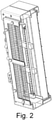
- Fig. 2
- eine Ausführungsform des Filtersystems gemäß
Fig. 1 in perspektivischer geschnittener Ansicht - Aus der Zeichnung ist der grundsätzliche Aufbau eines erfindungsgemäßen Filtersystems ersichtlich. Demzufolge umfasst dieses Filtersystem einen elektro-mechanischen Filter, der in einem vom Luftstrom "LS" durchströmbaren Gehäuse 6 angeordnet ist. Ein elektromechanischer Filter umfasst stets eine Baugruppe zur elektrostatischen Aufladung der auszufilternden Partikel. Dieser Aufbau ist dem Fachmann grundsätzlich bekannt, so dass an dieser Stelle auf nähere Darlegungen zum Funktionsprinzip verzichtet werden kann. Wesentlich im vorliegenden Sachverhalt ist jedoch, wie dieses bekannte Grundprinzip für eine Anwendung zum Reinigen von Luftströmen für Klimaanlagen von Schienenfahrzeugen modifiziert wird.
- Demzufolge besteht der elektro-mechanische Filter aus einer lonisierungseinheit "IE" und einer Abscheideeinheit "AE", die in einem gemeinsamen Gehäuse 6 mit Abstand zueinander angeordnet sind. Bezogen auf den Luftstrom "LS" ist dabei die Abscheideeinheit "AE" in Strömungsrichtung der lonisierungseinheit "IE" nachgelagert.
- Das Gehäuse 6 ist durch einen Erdungsanschluss mit dem Schienenfahrzeug verbunden und weist jeweils ein Eintrittsgitter 1 und ein Austrittsgitter 5 auf. Dabei ist das Eintrittsgitter 1 geerdet und als Kontrollelektrode ausgeführt. Das Austrittsgitter 5 ist als Erdungselektrode ausgeführt und ebenfalls mit dem Gehäuseerdpotential verbunden. Des Weiteren stellt das Austrittsgitter den großflächigen, leitenden Erdkontakt zur Aktivkohleschichtsicher, um die gewollten elektrostatischen Anziehungskräfte effektiv ausnutzen zu können. An der Vorderseite des Gehäuses 6 sind außerdem der Erdungsanschluss und die Durchführung der Hochspannungsleitung angeordnet, wobei diese Position auch an einer der beiden kurzen Seiten in Abhängigkeit von den räumlichen Randbedingungen und Schnittstellen gewählt werden kann.
- Die lonisierungseinheit "IE" weist zwei Elektroden auf, wobei eine als Sprühelektrode 2 bzw. Hochspannungselektrode 2 und die andere als Eintrittsgitter 1 oder Kontrollelektrode 1 ausgeführt ist. Die Sprühelektroden 2 sind hierbei in einem bestimmten Anordnungsmuster, mit einem bestimmten Abstand zur Kontrollelektrode 1 über den gesamten Lufteinströmquerschnitt verteilt angeordnet. Mit diesen Elektroden wird ein elektrisches Feld erzeugt (Korona Effekt), in dem der Luftstrom "LS" bzw. die darin enthaltenen Partikel eine elektrostatische Ladung erhalten. Wichtig hierbei ist für den Einsatz des Filtersystems, dass die Hochspannungselektrode (hier als Sammelbegriff für alle Sprühelektroden bezeichnet) gegen alle leitfähigen Bauteile außer Kontroll- und Erdelektrode, welche in Verbindung mit dem Gehäuse-Erdpotential stehen, mittels Isolationsmaterialien gegen einen Stromfluss geschützt wird. Damit soll sichergestellt werden, dass die gewünschten elektrischen Wechselwirkungen und Ströme ausschließlich der Luftbehandlung dienen und nicht unerwünschte Kurzschlüsse auftreten.
- Die Abscheideeinheit "AE" weist ein Kombifilterelement auf, das aus einem Filtervlies 3 und einer in Strömungsrichtung nachgelagerten Aktivkohleschicht 4 besteht,
- Weiterhin umfasst der elektro-mechanische Filter einen DC/DC-Wandler 7, der mit der Steuerspannung des Schienenfahrzeuges gespeist wird. Vorzugsweise erfolgt dies aus einer 110 V DC oder aus einer 24 V DC Versorgung des Schienenfahrzeuges, wobei auch andere Versorgungsspannungen möglich sind. Der Stromkreis zum DC/DC-Wandler 7 wird beim Öffnen des dem elektro-mechanischen-Filterzuganges zugehörigen Klimagerätedeckels selbsttätig unterbrochen.
- Die angelegte Hochspannung liegt in einem Bereich von 6 bis 10 kV und ist in Abhängigkeit der aktuellen Einsatzbedingungen zuschaltbar oder abschaltbar oder im bestimmungsgemäßen Betrieb permanent anliegend. Dabei kann das Anliegen der Hochspannung über einen Statusausgang am DC/DC-Wandler 7 überprüft werden. Der Anschluss für die Hochspannung ist vorzugsweise als ein Hochspannungssteckverbinder ausgestaltet, über den der elektro-mechanische Filter vor einem Ausbau elektrisch trennbar ist.
- Das erfindungsgemäße Filtersystem kann verschiedenartig weiter ausgestaltet werden, um weitere funktionelle Vorteile zu erreichen. Beispielsweise wird der elektro-mechanische Filter so dimensioniert, dass er bei der Nachrüstung bestehender Systeme innerhalb der existierenden Filteraufnahme des Klimagerätes ohne wesentliche konstruktive Änderungen integriert werden kann. Weiterhin ist eine Überwachung der Filterbeladung möglich, indem auf Grundlage einer Differenzdruckmessung oder einer optischen Detektion der Filteroberfläche eine Mitteilung ausgelöst wird, sobald ein Tausch oder eine Wartung notwendig sind. Ferner kann das Kombifilterelement mit einem rollenförmig ausgestalteten Filtervlies 3 oder mit einer rollenförmig ausgestalteten Aktivkohleschicht 4 ausgeführt werden. Sofern diese mit der Überwachung der Filterbeladung in Wirkverbindung stehen, werden sie bedarfsweise manuell oder elektromotorisch verlagert, so dass stets funktionsfähige Filterkomponenten verfügbar sind.
Claims (4)
- Filtersystem zum Reinigen von Luft, geeignet für Schienenfahrzeuge, bei denen die Luft mittels Heizungs-, Lüftungs- und Klimaanlagen den Aufenthaltsbereichen von Personen zu- bzw. aus diesen abgeführt wird, wobei das Filtersystem einen elektro-mechanischen Filter umfasst, der in einem vom Luftstrom durchströmbaren Gehäuse angeordnet ist und der eine Baugruppe zur elektrostatischen Aufladung der in der Luft enthaltenen Partikel in Kombination mit einem mechanischen Filterelement aufweist, wobei der elektro-mechanische Filter aus einer lonisierungseinheit (IE), einer in Strömungsrichtung nachgelagerten Abscheideeinheit (AE) und aus einem DC/DC-Wandler (7) besteht, wobei die lonisierungseinheit (IE) zwei Elektroden aufweist, mit denen ein elektrisches Feld erzeugbar ist, in dem der Luftstrom (LS) bzw. die darin enthaltenen Partikel eine elektrostatische Ladung erhalten, wobei die Abscheideeinheit (AE) ein Kombifilterelement aufweist, das aus einem Filtervlies (3) und einer in Strömungsrichtung nachgelagerten Aktivkohleschicht (4) besteht, wobei der DC/DC-Wandler (7) die notwendige Hochspannung für die lonisierungseinheit (IE) zur Verfügung stellt und
dafür ausgelegt ist, mit der Steuerspannung des Schienenfahrzeuges gespeist zu werden, wobei das Gehäuse (6) durch einen Erdungsanschluss mit dem Schienenfahrzeug verbindbar ist und ein Eintrittsgitter (1) und ein Austrittsgitter (5) aufweist, wobei das Eintrittsgitter (1) geerdet und als eine Kontrollelektrode und das Austrittsgitter (5) als eine Erdungselektrode ausgeführt ist, wobei der Erdungsanschluss und die Durchführung der Hochspannungsleitung an der Vorderseite oder den Seitenteilen des Gehäuses (6) angeordnet sind, wobei die angelegte Hochspannung in einem Bereich von 6 bis 10 kV liegt und entweder beim bestimmungsgemäßen Betrieb zugeschaltet ist oder bedarfsweise zuschaltbar oder abschaltbar ist, wobei das Anliegen der Hochspannung über einen Statusausgang am DC/DC-Wandler (7) überprüfbar ist und wobei der Anschluss für die Hochspannung als ein Hochspannungssteckverbinder oder als ein funktionsgleiches Bauteil ausgestaltet ist, über den/das der elektro-mechanische Filter vor einem Ausbau elektrisch trennbar ist. - Filtersystem nach Anspruch 1, dadurch gekennzeichnet,
dass beim Öffnen des Klimagerätedeckels der Stromkreis zum DC/DC-Wandler (7) selbsttätig unterbrochen wird. - Filtersystem nach Anspruch 1, dadurch gekennzeichnet,
dass eine Überwachung der Filterbeladung erfolgt, indem auf Grundlage einer Differenzdruckmessung oder einer optischen Detektion der Filteroberfläche bzw. eines definierten Bereiches der Filteroberfläche eine Mitteilung ausgelöst wird, dass ein Tausch oder eine Wartung notwendig sind. - Filtersystem nach Anspruch 3, dadurch gekennzeichnet,
dass das Kombifilterelement ein rollenförmig ausgestaltetes Filtervlies (3) und/oder eine rollenförmig ausgestaltete Aktivkohleschicht (4) aufweist, die mit der Überwachung der Filterbeladung in Wirkverbindung stehen und bedarfsweise manuell oder elektromotorisch verlagerbar sind.
Applications Claiming Priority (2)
| Application Number | Priority Date | Filing Date | Title |
|---|---|---|---|
| DE102016115441.5A DE102016115441A1 (de) | 2016-08-19 | 2016-08-19 | Elektro-mechanisches Filtersystem zum Reinigen von Luft in Schienenfahrzeugen |
| PCT/DE2017/100573 WO2018033172A1 (de) | 2016-08-19 | 2017-07-12 | Elektro-mechanisches filtersystem zum reinigen von luft in schienenfahrzeugen |
Publications (2)
| Publication Number | Publication Date |
|---|---|
| EP3500801A1 EP3500801A1 (de) | 2019-06-26 |
| EP3500801B1 true EP3500801B1 (de) | 2022-03-23 |
Family
ID=59713738
Family Applications (1)
| Application Number | Title | Priority Date | Filing Date |
|---|---|---|---|
| EP17758027.1A Active EP3500801B1 (de) | 2016-08-19 | 2017-07-12 | Elektro-mechanisches filtersystem zum reinigen von luft in schienenfahrzeugen |
Country Status (3)
| Country | Link |
|---|---|
| EP (1) | EP3500801B1 (de) |
| DE (1) | DE102016115441A1 (de) |
| WO (1) | WO2018033172A1 (de) |
Families Citing this family (18)
| Publication number | Priority date | Publication date | Assignee | Title |
|---|---|---|---|---|
| CN109520041B (zh) * | 2018-11-21 | 2021-02-05 | 深圳丰威源自动化设备有限公司 | 一种带智能芯片检测的空气净化器滤网 |
| CN109398395A (zh) * | 2018-12-07 | 2019-03-01 | 合肥中车轨道交通车辆有限公司 | 一种轨道车辆空调用空气净化器及其控制方法 |
| DE102020121872B4 (de) | 2020-08-20 | 2025-08-07 | Dornier New Technologies GmbH | Fahrzeuginnenraum-Luftreinigungssystem |
| DE102021114015A1 (de) | 2021-05-31 | 2022-12-01 | Audi Aktiengesellschaft | Klimatisierungssystem mit Elektrofilter, Kraftfahrzeug mit einem solchen Klimatisierungssystem und Verfahren zum Betreiben eines solchen Klimatisierungssystems |
| EP4342586A4 (de) * | 2021-11-17 | 2024-11-13 | Samsung Electronics Co., Ltd. | Elektrischer abscheider und verfahren zur steuerung davon |
| CN117651614A (zh) * | 2021-11-17 | 2024-03-05 | 三星电子株式会社 | 电集尘装置及其控制方法 |
| CN114135969B (zh) * | 2021-11-25 | 2024-02-09 | 爱优特空气技术(上海)有限公司 | 一种自供热水清洗兼除湿的隧道净化系统 |
| DE102021213417A1 (de) * | 2021-11-29 | 2023-06-01 | Mahle International Gmbh | Lüftungseinrichtung |
| CN114198856B (zh) * | 2021-12-09 | 2023-05-09 | 德州清润德健健康科技有限公司 | 净化装置及空气消杀设备 |
| DE102022102953B3 (de) | 2022-02-09 | 2023-03-02 | Audi Aktiengesellschaft | Belüftungseinrichtung für ein Kraftfahrzeug, Kraftfahrzeug und Verfahren zum Betreiben einer Belüftungseinrichtung |
| DE102023206813A1 (de) * | 2023-07-18 | 2025-01-23 | Karlsruher Institut für Technologie (KIT), Körperschaft des öffentlichen Rechts | Luftfiltereinrichtung für eine Klimatisierungsanlage |
| DE102023206812A1 (de) * | 2023-07-18 | 2025-01-23 | Karlsruher Institut für Technologie (KIT), Körperschaft des öffentlichen Rechts | Luftfiltereinrichtung für eine Klimatisierungsanlage |
| DE102023206804A1 (de) * | 2023-07-18 | 2025-01-23 | Karlsruher Institut für Technologie (KIT), Körperschaft des öffentlichen Rechts | Luftfiltervorrichtung sowie damit ausgerüstetes Fahrzeugklimagerät |
| DE102023206818A1 (de) * | 2023-07-18 | 2025-01-23 | Karlsruher Institut für Technologie (KIT), Körperschaft des öffentlichen Rechts | Luftreinigungsverfahren und Heizung-, Lüftungs- und Klimatisierungs-System |
| DE102023206819A1 (de) * | 2023-07-18 | 2025-01-23 | Karlsruher Institut für Technologie (KIT), Körperschaft des öffentlichen Rechts | Luftreinigungsverfahren und Heizung-, Lüftungs- und Klimatisierungs-System |
| DE102024107586A1 (de) * | 2024-03-18 | 2025-09-18 | Mahle International Gmbh | Ionisationseinrichtung, Luftfiltereinrichtung und Klimagerät |
| DE102024112980A1 (de) * | 2024-05-08 | 2025-11-13 | Mahle International Gmbh | Luftfiltereinrichtung |
| DE102024133069A1 (de) * | 2024-11-12 | 2026-05-13 | Mahle International Gmbh | Reinigungseinrichtung zur Reinigung von Luft |
Citations (1)
| Publication number | Priority date | Publication date | Assignee | Title |
|---|---|---|---|---|
| US5403383A (en) * | 1992-08-26 | 1995-04-04 | Jaisinghani; Rajan | Safe ionizing field electrically enhanced filter and process for safely ionizing a field of an electrically enhanced filter |
Family Cites Families (11)
| Publication number | Priority date | Publication date | Assignee | Title |
|---|---|---|---|---|
| DE3723544A1 (de) | 1987-07-16 | 1989-01-26 | Man Technologie Gmbh | Elektrostatischer filter zum reinigen von gasen |
| GB2232908A (en) * | 1989-06-15 | 1991-01-02 | Honeywell Control Syst | Electrostatic fluid cleaner |
| US5330559A (en) * | 1992-08-11 | 1994-07-19 | United Air Specialists, Inc. | Method and apparatus for electrostatically cleaning particulates from air |
| FR2838380B1 (fr) * | 2002-04-12 | 2006-01-06 | Valeo Climatisation | Purification de l'air de l'habitacle d'un vehicule par absorption et photocatalyse |
| FR2859666B1 (fr) * | 2003-09-12 | 2006-03-10 | Valeo Climatisation | Installation de chauffage/climatisation de vehicule automobile a flux d'air filtre |
| WO2006072235A1 (de) * | 2005-01-07 | 2006-07-13 | Efs Schermbeck Gmbh | Verfahren und vorrichtung zur reinigung und konditionierung von luft |
| DE202006004522U1 (de) | 2006-03-22 | 2006-06-08 | Blue Corporate Finance Gmbh & Co. Kg | Fahrzeuge und Systeme mit Feinstaubfilter |
| DE102009026010A1 (de) | 2008-06-24 | 2010-01-14 | Solmaz, Bülent | Elektrostatische Abscheidevorrichtung für ein Kraftfahrzeug |
| DE102008049279A1 (de) * | 2008-09-26 | 2010-04-01 | Behr Gmbh & Co. Kg | Ionisationsvorrichtung |
| DE202009016307U1 (de) * | 2009-12-02 | 2010-03-18 | Behr Gmbh & Co. Kg | Elektroabscheider zur Abscheidung von Partikeln aus einem Gasstrom |
| DE102011119843B4 (de) * | 2011-09-30 | 2018-04-12 | Airbus Defence and Space GmbH | Kabinenluftreinigungsvorrichtung zur Reinigung von Luft für eine Kabine eines Transportmittels |
-
2016
- 2016-08-19 DE DE102016115441.5A patent/DE102016115441A1/de not_active Withdrawn
-
2017
- 2017-07-12 WO PCT/DE2017/100573 patent/WO2018033172A1/de not_active Ceased
- 2017-07-12 EP EP17758027.1A patent/EP3500801B1/de active Active
Patent Citations (1)
| Publication number | Priority date | Publication date | Assignee | Title |
|---|---|---|---|---|
| US5403383A (en) * | 1992-08-26 | 1995-04-04 | Jaisinghani; Rajan | Safe ionizing field electrically enhanced filter and process for safely ionizing a field of an electrically enhanced filter |
Also Published As
| Publication number | Publication date |
|---|---|
| WO2018033172A1 (de) | 2018-02-22 |
| DE102016115441A1 (de) | 2018-02-22 |
| EP3500801A1 (de) | 2019-06-26 |
Similar Documents
| Publication | Publication Date | Title |
|---|---|---|
| WO2018033172A1 (de) | Elektro-mechanisches filtersystem zum reinigen von luft in schienenfahrzeugen | |
| EP4048955B1 (de) | Dunstabzugshaube mit elektrostatischer filtereinheit | |
| EP3934811B1 (de) | Luftreinigungsvorrichtung mit elektrostatischer filtereinheit | |
| DE102008011949A1 (de) | Elektrostatischer Abscheider | |
| DE102021213417A1 (de) | Lüftungseinrichtung | |
| WO2017121442A1 (de) | Vorrichtung zur abscheidung ultrafeiner partikel (ufp) aus einem in kraftfahrzeugbelüftungs- und -klimatisierungsanlagen fliessenden luftstrom | |
| WO2021099112A1 (de) | Filtereinheit für luftreinigungsvorrichtung und luftreinigungsvorrichtung | |
| WO2021099110A1 (de) | Elektrostatische filtereinheit für luftreinigungsvorrichtung und luftreinigungsvorrichtung | |
| WO2025031761A1 (de) | Filtergehäuse, filtereinsatz und filtereinheit mit polarisationsfilter und elektrostatischem abscheider | |
| EP1976639A1 (de) | Vorrichtung zur luftreinigung, insbesondere für lüftungs- und klimaanlagen | |
| DE102011119843B4 (de) | Kabinenluftreinigungsvorrichtung zur Reinigung von Luft für eine Kabine eines Transportmittels | |
| EP4255610A1 (de) | Luftreinigungseinrichtung und luftreinigungssystem sowie verfahren zur reinigung einer luftreinigungseinrichtung und eines luftreinigungssystems | |
| DE102017214495A1 (de) | Filtereinheit für Luftreinigungsvorrichtung und Luftreinigungsvorrichtung | |
| DE112024000932T5 (de) | Elektrostatische Staubabscheidevorrichtung von Bremssatteltyp und Fahrzeugbremsvorrichtung damit | |
| DE102023206819A1 (de) | Luftreinigungsverfahren und Heizung-, Lüftungs- und Klimatisierungs-System | |
| DE19841973C2 (de) | Aus Sprühelektroden und einer Niederschlagselektrode gebildete Elektro-Filterstufe | |
| DE102021132295A1 (de) | Vorrichtung zum Filtern eines mit Partikeln verunreinigten Luftstroms | |
| DE112015007142B4 (de) | Entladevorrichtung und mit dieser ausgestattetes Klimagerät | |
| DE202009016307U1 (de) | Elektroabscheider zur Abscheidung von Partikeln aus einem Gasstrom | |
| DE102024115686A1 (de) | Luftfiltereinrichtung und Kraftfahrzeug | |
| DE102024111978A1 (de) | Luftfiltereinheit und Luftfiltereinrichtung | |
| DE102023206805A1 (de) | Luftfiltervorrichtung sowie damit ausgerüstetes Fahrzeugklimagerät | |
| DE102023206793A1 (de) | Reinigungseinrichtung zur Reinigung von Luft | |
| DE202010015834U1 (de) | Elektroabscheider zur Abscheidung von Partikeln aus einem Gasstrom | |
| DE202025101038U1 (de) | Filtereinrichtung und Klimatisierungseinrichtung |
Legal Events
| Date | Code | Title | Description |
|---|---|---|---|
| STAA | Information on the status of an ep patent application or granted ep patent |
Free format text: STATUS: UNKNOWN |
|
| STAA | Information on the status of an ep patent application or granted ep patent |
Free format text: STATUS: THE INTERNATIONAL PUBLICATION HAS BEEN MADE |
|
| PUAI | Public reference made under article 153(3) epc to a published international application that has entered the european phase |
Free format text: ORIGINAL CODE: 0009012 |
|
| STAA | Information on the status of an ep patent application or granted ep patent |
Free format text: STATUS: REQUEST FOR EXAMINATION WAS MADE |
|
| 17P | Request for examination filed |
Effective date: 20190317 |
|
| AK | Designated contracting states |
Kind code of ref document: A1 Designated state(s): AL AT BE BG CH CY CZ DE DK EE ES FI FR GB GR HR HU IE IS IT LI LT LU LV MC MK MT NL NO PL PT RO RS SE SI SK SM TR |
|
| AX | Request for extension of the european patent |
Extension state: BA ME |
|
| DAV | Request for validation of the european patent (deleted) | ||
| DAX | Request for extension of the european patent (deleted) | ||
| STAA | Information on the status of an ep patent application or granted ep patent |
Free format text: STATUS: EXAMINATION IS IN PROGRESS |
|
| 17Q | First examination report despatched |
Effective date: 20210129 |
|
| REG | Reference to a national code |
Ref country code: DE Ref legal event code: R079 Ref document number: 502017012820 Country of ref document: DE Free format text: PREVIOUS MAIN CLASS: F24F0003160000 Ipc: F24F0007007000 |
|
| RIC1 | Information provided on ipc code assigned before grant |
Ipc: F24F 8/10 20210101ALI20210909BHEP Ipc: B61D 27/00 20060101ALI20210909BHEP Ipc: B01D 46/52 20060101ALI20210909BHEP Ipc: B01D 46/00 20060101ALI20210909BHEP Ipc: F24F 8/158 20210101ALI20210909BHEP Ipc: B60H 3/00 20060101ALI20210909BHEP Ipc: F24F 8/192 20210101ALI20210909BHEP Ipc: B60H 3/06 20060101ALI20210909BHEP Ipc: B03C 3/04 20060101ALI20210909BHEP Ipc: B03C 3/017 20060101ALI20210909BHEP Ipc: B01D 46/50 20060101ALI20210909BHEP Ipc: B01D 46/10 20060101ALI20210909BHEP Ipc: F24F 13/28 20060101ALI20210909BHEP Ipc: F24F 8/90 20210101ALI20210909BHEP Ipc: F24F 8/30 20210101ALI20210909BHEP Ipc: F24F 8/108 20210101ALI20210909BHEP Ipc: F24F 7/007 20060101AFI20210909BHEP |
|
| GRAP | Despatch of communication of intention to grant a patent |
Free format text: ORIGINAL CODE: EPIDOSNIGR1 |
|
| STAA | Information on the status of an ep patent application or granted ep patent |
Free format text: STATUS: GRANT OF PATENT IS INTENDED |
|
| INTG | Intention to grant announced |
Effective date: 20211029 |
|
| GRAS | Grant fee paid |
Free format text: ORIGINAL CODE: EPIDOSNIGR3 |
|
| GRAA | (expected) grant |
Free format text: ORIGINAL CODE: 0009210 |
|
| STAA | Information on the status of an ep patent application or granted ep patent |
Free format text: STATUS: THE PATENT HAS BEEN GRANTED |
|
| AK | Designated contracting states |
Kind code of ref document: B1 Designated state(s): AL AT BE BG CH CY CZ DE DK EE ES FI FR GB GR HR HU IE IS IT LI LT LU LV MC MK MT NL NO PL PT RO RS SE SI SK SM TR |
|
| REG | Reference to a national code |
Ref country code: GB Ref legal event code: FG4D Free format text: NOT ENGLISH |
|
| REG | Reference to a national code |
Ref country code: CH Ref legal event code: EP |
|
| REG | Reference to a national code |
Ref country code: IE Ref legal event code: FG4D Free format text: LANGUAGE OF EP DOCUMENT: GERMAN |
|
| REG | Reference to a national code |
Ref country code: DE Ref legal event code: R096 Ref document number: 502017012820 Country of ref document: DE |
|
| REG | Reference to a national code |
Ref country code: AT Ref legal event code: REF Ref document number: 1477689 Country of ref document: AT Kind code of ref document: T Effective date: 20220415 |
|
| GRAL | Information related to payment of fee for publishing/printing deleted |
Free format text: ORIGINAL CODE: EPIDOSDIGR3 |
|
| GRAS | Grant fee paid |
Free format text: ORIGINAL CODE: EPIDOSNIGR3 |
|
| REG | Reference to a national code |
Ref country code: LT Ref legal event code: MG9D |
|
| REG | Reference to a national code |
Ref country code: NL Ref legal event code: MP Effective date: 20220323 |
|
| PG25 | Lapsed in a contracting state [announced via postgrant information from national office to epo] |
Ref country code: SE Free format text: LAPSE BECAUSE OF FAILURE TO SUBMIT A TRANSLATION OF THE DESCRIPTION OR TO PAY THE FEE WITHIN THE PRESCRIBED TIME-LIMIT Effective date: 20220323 Ref country code: RS Free format text: LAPSE BECAUSE OF FAILURE TO SUBMIT A TRANSLATION OF THE DESCRIPTION OR TO PAY THE FEE WITHIN THE PRESCRIBED TIME-LIMIT Effective date: 20220323 Ref country code: NO Free format text: LAPSE BECAUSE OF FAILURE TO SUBMIT A TRANSLATION OF THE DESCRIPTION OR TO PAY THE FEE WITHIN THE PRESCRIBED TIME-LIMIT Effective date: 20220623 Ref country code: LT Free format text: LAPSE BECAUSE OF FAILURE TO SUBMIT A TRANSLATION OF THE DESCRIPTION OR TO PAY THE FEE WITHIN THE PRESCRIBED TIME-LIMIT Effective date: 20220323 Ref country code: HR Free format text: LAPSE BECAUSE OF FAILURE TO SUBMIT A TRANSLATION OF THE DESCRIPTION OR TO PAY THE FEE WITHIN THE PRESCRIBED TIME-LIMIT Effective date: 20220323 Ref country code: BG Free format text: LAPSE BECAUSE OF FAILURE TO SUBMIT A TRANSLATION OF THE DESCRIPTION OR TO PAY THE FEE WITHIN THE PRESCRIBED TIME-LIMIT Effective date: 20220623 |
|
| PG25 | Lapsed in a contracting state [announced via postgrant information from national office to epo] |
Ref country code: LV Free format text: LAPSE BECAUSE OF FAILURE TO SUBMIT A TRANSLATION OF THE DESCRIPTION OR TO PAY THE FEE WITHIN THE PRESCRIBED TIME-LIMIT Effective date: 20220323 Ref country code: GR Free format text: LAPSE BECAUSE OF FAILURE TO SUBMIT A TRANSLATION OF THE DESCRIPTION OR TO PAY THE FEE WITHIN THE PRESCRIBED TIME-LIMIT Effective date: 20220624 Ref country code: FI Free format text: LAPSE BECAUSE OF FAILURE TO SUBMIT A TRANSLATION OF THE DESCRIPTION OR TO PAY THE FEE WITHIN THE PRESCRIBED TIME-LIMIT Effective date: 20220323 |
|
| PG25 | Lapsed in a contracting state [announced via postgrant information from national office to epo] |
Ref country code: NL Free format text: LAPSE BECAUSE OF FAILURE TO SUBMIT A TRANSLATION OF THE DESCRIPTION OR TO PAY THE FEE WITHIN THE PRESCRIBED TIME-LIMIT Effective date: 20220323 |
|
| PG25 | Lapsed in a contracting state [announced via postgrant information from national office to epo] |
Ref country code: SM Free format text: LAPSE BECAUSE OF FAILURE TO SUBMIT A TRANSLATION OF THE DESCRIPTION OR TO PAY THE FEE WITHIN THE PRESCRIBED TIME-LIMIT Effective date: 20220323 Ref country code: SK Free format text: LAPSE BECAUSE OF FAILURE TO SUBMIT A TRANSLATION OF THE DESCRIPTION OR TO PAY THE FEE WITHIN THE PRESCRIBED TIME-LIMIT Effective date: 20220323 Ref country code: RO Free format text: LAPSE BECAUSE OF FAILURE TO SUBMIT A TRANSLATION OF THE DESCRIPTION OR TO PAY THE FEE WITHIN THE PRESCRIBED TIME-LIMIT Effective date: 20220323 Ref country code: PT Free format text: LAPSE BECAUSE OF FAILURE TO SUBMIT A TRANSLATION OF THE DESCRIPTION OR TO PAY THE FEE WITHIN THE PRESCRIBED TIME-LIMIT Effective date: 20220725 Ref country code: ES Free format text: LAPSE BECAUSE OF FAILURE TO SUBMIT A TRANSLATION OF THE DESCRIPTION OR TO PAY THE FEE WITHIN THE PRESCRIBED TIME-LIMIT Effective date: 20220323 Ref country code: EE Free format text: LAPSE BECAUSE OF FAILURE TO SUBMIT A TRANSLATION OF THE DESCRIPTION OR TO PAY THE FEE WITHIN THE PRESCRIBED TIME-LIMIT Effective date: 20220323 |
|
| PG25 | Lapsed in a contracting state [announced via postgrant information from national office to epo] |
Ref country code: PL Free format text: LAPSE BECAUSE OF FAILURE TO SUBMIT A TRANSLATION OF THE DESCRIPTION OR TO PAY THE FEE WITHIN THE PRESCRIBED TIME-LIMIT Effective date: 20220323 Ref country code: IS Free format text: LAPSE BECAUSE OF FAILURE TO SUBMIT A TRANSLATION OF THE DESCRIPTION OR TO PAY THE FEE WITHIN THE PRESCRIBED TIME-LIMIT Effective date: 20220723 Ref country code: AL Free format text: LAPSE BECAUSE OF FAILURE TO SUBMIT A TRANSLATION OF THE DESCRIPTION OR TO PAY THE FEE WITHIN THE PRESCRIBED TIME-LIMIT Effective date: 20220323 |
|
| REG | Reference to a national code |
Ref country code: DE Ref legal event code: R097 Ref document number: 502017012820 Country of ref document: DE |
|
| PLBE | No opposition filed within time limit |
Free format text: ORIGINAL CODE: 0009261 |
|
| STAA | Information on the status of an ep patent application or granted ep patent |
Free format text: STATUS: NO OPPOSITION FILED WITHIN TIME LIMIT |
|
| PG25 | Lapsed in a contracting state [announced via postgrant information from national office to epo] |
Ref country code: DK Free format text: LAPSE BECAUSE OF FAILURE TO SUBMIT A TRANSLATION OF THE DESCRIPTION OR TO PAY THE FEE WITHIN THE PRESCRIBED TIME-LIMIT Effective date: 20220323 |
|
| PG25 | Lapsed in a contracting state [announced via postgrant information from national office to epo] |
Ref country code: MC Free format text: LAPSE BECAUSE OF FAILURE TO SUBMIT A TRANSLATION OF THE DESCRIPTION OR TO PAY THE FEE WITHIN THE PRESCRIBED TIME-LIMIT Effective date: 20220323 |
|
| 26N | No opposition filed |
Effective date: 20230102 |
|
| REG | Reference to a national code |
Ref country code: BE Ref legal event code: MM Effective date: 20220731 |
|
| PG25 | Lapsed in a contracting state [announced via postgrant information from national office to epo] |
Ref country code: LU Free format text: LAPSE BECAUSE OF NON-PAYMENT OF DUE FEES Effective date: 20220712 |
|
| PG25 | Lapsed in a contracting state [announced via postgrant information from national office to epo] |
Ref country code: SI Free format text: LAPSE BECAUSE OF FAILURE TO SUBMIT A TRANSLATION OF THE DESCRIPTION OR TO PAY THE FEE WITHIN THE PRESCRIBED TIME-LIMIT Effective date: 20220323 Ref country code: BE Free format text: LAPSE BECAUSE OF NON-PAYMENT OF DUE FEES Effective date: 20220731 |
|
| P01 | Opt-out of the competence of the unified patent court (upc) registered |
Effective date: 20230530 |
|
| PG25 | Lapsed in a contracting state [announced via postgrant information from national office to epo] |
Ref country code: IE Free format text: LAPSE BECAUSE OF NON-PAYMENT OF DUE FEES Effective date: 20220712 |
|
| PG25 | Lapsed in a contracting state [announced via postgrant information from national office to epo] |
Ref country code: HU Free format text: LAPSE BECAUSE OF FAILURE TO SUBMIT A TRANSLATION OF THE DESCRIPTION OR TO PAY THE FEE WITHIN THE PRESCRIBED TIME-LIMIT; INVALID AB INITIO Effective date: 20170712 |
|
| PG25 | Lapsed in a contracting state [announced via postgrant information from national office to epo] |
Ref country code: MK Free format text: LAPSE BECAUSE OF FAILURE TO SUBMIT A TRANSLATION OF THE DESCRIPTION OR TO PAY THE FEE WITHIN THE PRESCRIBED TIME-LIMIT Effective date: 20220323 Ref country code: CY Free format text: LAPSE BECAUSE OF FAILURE TO SUBMIT A TRANSLATION OF THE DESCRIPTION OR TO PAY THE FEE WITHIN THE PRESCRIBED TIME-LIMIT Effective date: 20220323 |
|
| PG25 | Lapsed in a contracting state [announced via postgrant information from national office to epo] |
Ref country code: MT Free format text: LAPSE BECAUSE OF FAILURE TO SUBMIT A TRANSLATION OF THE DESCRIPTION OR TO PAY THE FEE WITHIN THE PRESCRIBED TIME-LIMIT Effective date: 20220323 |
|
| REG | Reference to a national code |
Ref country code: DE Ref legal event code: R081 Ref document number: 502017012820 Country of ref document: DE Owner name: WABTEC GERMANY GMBH, DE Free format text: FORMER OWNER: FAIVELEY TRANSPORT LEIPZIG GMBH & CO. KG, 04435 SCHKEUDITZ, DE |
|
| PGFP | Annual fee paid to national office [announced via postgrant information from national office to epo] |
Ref country code: GB Payment date: 20250618 Year of fee payment: 9 |
|
| PGFP | Annual fee paid to national office [announced via postgrant information from national office to epo] |
Ref country code: FR Payment date: 20250618 Year of fee payment: 9 |
|
| PGFP | Annual fee paid to national office [announced via postgrant information from national office to epo] |
Ref country code: CZ Payment date: 20250627 Year of fee payment: 9 |
|
| PGFP | Annual fee paid to national office [announced via postgrant information from national office to epo] |
Ref country code: DE Payment date: 20250618 Year of fee payment: 9 |
|
| PGFP | Annual fee paid to national office [announced via postgrant information from national office to epo] |
Ref country code: IT Payment date: 20250618 Year of fee payment: 9 |
|
| PGFP | Annual fee paid to national office [announced via postgrant information from national office to epo] |
Ref country code: AT Payment date: 20250618 Year of fee payment: 9 |
|
| PGFP | Annual fee paid to national office [announced via postgrant information from national office to epo] |
Ref country code: CH Payment date: 20250801 Year of fee payment: 9 |
|
| PG25 | Lapsed in a contracting state [announced via postgrant information from national office to epo] |
Ref country code: TR Free format text: LAPSE BECAUSE OF FAILURE TO SUBMIT A TRANSLATION OF THE DESCRIPTION OR TO PAY THE FEE WITHIN THE PRESCRIBED TIME-LIMIT Effective date: 20220323 |