EP3500729B1 - Verfahren zur erstellung einer kontinuierlichen pvt-phasenhüllkurvenlogs - Google Patents
Verfahren zur erstellung einer kontinuierlichen pvt-phasenhüllkurvenlogs Download PDFInfo
- Publication number
- EP3500729B1 EP3500729B1 EP17842055.0A EP17842055A EP3500729B1 EP 3500729 B1 EP3500729 B1 EP 3500729B1 EP 17842055 A EP17842055 A EP 17842055A EP 3500729 B1 EP3500729 B1 EP 3500729B1
- Authority
- EP
- European Patent Office
- Prior art keywords
- fluid
- pvt
- phase
- fluid sample
- phase envelope
- Prior art date
- Legal status (The legal status is an assumption and is not a legal conclusion. Google has not performed a legal analysis and makes no representation as to the accuracy of the status listed.)
- Active
Links
Images

Classifications
-
- E—FIXED CONSTRUCTIONS
- E21—EARTH OR ROCK DRILLING; MINING
- E21B—EARTH OR ROCK DRILLING; OBTAINING OIL, GAS, WATER, SOLUBLE OR MELTABLE MATERIALS OR A SLURRY OF MINERALS FROM WELLS
- E21B49/00—Testing the nature of borehole walls; Formation testing; Methods or apparatus for obtaining samples of soil or well fluids, specially adapted to earth drilling or wells
- E21B49/005—Testing the nature of borehole walls or the formation by using drilling mud or cutting data
-
- E—FIXED CONSTRUCTIONS
- E21—EARTH OR ROCK DRILLING; MINING
- E21B—EARTH OR ROCK DRILLING; OBTAINING OIL, GAS, WATER, SOLUBLE OR MELTABLE MATERIALS OR A SLURRY OF MINERALS FROM WELLS
- E21B49/00—Testing the nature of borehole walls; Formation testing; Methods or apparatus for obtaining samples of soil or well fluids, specially adapted to earth drilling or wells
- E21B49/08—Obtaining fluid samples or testing fluids, in boreholes or wells
- E21B49/081—Obtaining fluid samples or testing fluids, in boreholes or wells with down-hole means for trapping a fluid sample
-
- E—FIXED CONSTRUCTIONS
- E21—EARTH OR ROCK DRILLING; MINING
- E21B—EARTH OR ROCK DRILLING; OBTAINING OIL, GAS, WATER, SOLUBLE OR MELTABLE MATERIALS OR A SLURRY OF MINERALS FROM WELLS
- E21B49/00—Testing the nature of borehole walls; Formation testing; Methods or apparatus for obtaining samples of soil or well fluids, specially adapted to earth drilling or wells
- E21B49/08—Obtaining fluid samples or testing fluids, in boreholes or wells
- E21B49/086—Withdrawing samples at the surface
Definitions
- the present disclosure relates to characterizing underground formations and/or features. In further aspects, the present disclosure relates to methods and devices for generating PVT phase envelope logs for a subterranean formation.
- Wells, tunnels, and other similar holes formed in the earth may be used to access geothermal sources, water, hydrocarbons, minerals, etc. and may also be used to provide conduits or passages for equipment such as pipelines.
- a hole is commonly referred to as a borehole or wellbore of a well and any point within the borehole is generally referred to as being downhole.
- Boreholes are commonly used in significant capital commercial developments, such as hydrocarbon fields. Therefore, before field development begins, operators desire to have as much information as possible in order to evaluate the reservoir for commercial viability. Such information may be acquired at the seismic exploration phase, during well construction, prior to well completion and / or any time thereafter.
- PVT is an acronym used to refer to pressure, volume and temperature.
- PVT phase envelopes are used to characterize a fluid. Such phase envelopes are estimated from chemical composition together with pressure and temperature data. Bubble point, dew point, asphaltene dropout point, critical temperature and other PVT properties can be inferred from the PVT phase envelope. Knowing such information allows for the adjustment of the design of the production and surface equipment to take into account the actual PVT properties. US2007/119244A1 or WO2014158376A1 disclose prior art systems.
- the present disclosure is directed to devices, systems and methods that may be utilized to obtain or improve information that may be used for obtaining a PVT phase envelope and / or PVT properties log.
- the present disclosure provides a method for generating a phase envelope log to characterize a subsurface formation intersected by a borehole according to claim 1.
- the present disclosure provides a system for generating a phase envelope log to characterize a subsurface formation intersected by a borehole according to claim 14
- the present disclosure relates to devices and methods for continuously obtaining a PVT phase envelope log while drilling a borehole.
- continuous it is meant that the disclosed methodology enables the determination of PVT phase envelopes while drilling or at discrete stopping points during drilling and combining those envelopes to derive a representation of PVT properties along the measured depth of a borehole.
- PVT phase envelopes and properties are shown in the drawings, and herein will be described in detail, specific embodiments of the present disclosure with the understanding that the present disclosure is to be considered an exemplification of the principles described herein, and is not intended to limit the disclosure to that illustrated and described herein. Accordingly, the embodiments discussed below are merely illustrative of the applications of the present disclosure.
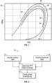
- FIG. 1 there is shown an exemplary PVT phase envelope 50 for a formation fluid that may be generated using the present teachings. Temperature is along the "X" axis 52 and pressure is along the "Y" axis 54. An outer curve 56 and an inner curve 58 bound the uncertainty around a PVT phase envelope 60. Generally speaking, the curves 56, 58, represent an uncertainty range of calculated pressure, volume, and temperature values at which a reservoir fluid or subsurface fluid may transition to or from a gas, liquid, or a mixture, which is commonly referred to as a phase transition.
- a region 62 along curve 60 may identify a "bubble point” and a region 64 along the curve 60 may identify a "dew point.”
- a PVT parameter is one or more of pressure, volume and temperature.
- a PVT property includes, but is not limited to, bubble point, dew point, asphaltene dropout point, gas-oil ratio, API gravity, viscosity, saturation pressure, formation volume factor, molecular weight, density and oil compressibility. Knowing such information allows for the adjustment of the design of the production and surface equipment to take into account the actual PVT properties.
- phase envelopes may be derived using data acquired at different depths along a borehole trajectory.
- the comparison of PVT properties and / or the PVT envelopes provides a means to characterize a subsurface formation; hence a combination of multiple PVT phase envelopes into a continuous log along a well trajectory may be used for such characterization.
- Multiple PVT phase envelopes may thus be arranged with measured depth along the well trajectory and areas without information about the phase envelope may be filled by interpolating between two adjacent phase envelopes.
- phase envelopes may be extrapolated to extend a phase envelope log.
- Phase envelope logs may also be re-sampled to derive a continuous, equally sampled log of phase envelopes.
- Phase envelope logs may then be displayed on a computer to allow a user to characterize a subsurface formation.
- such logs may be displayed as a tube-like representation around a well trajectory, and other formation evaluation logs may be displayed together with the phase envelope log.
- a gamma ray log, a neutron-density log, a magnetic resonance log, an acoustic log, a resistivity log, or a combination thereof may be used in addition to the phase envelope log to characterize a subsurface formation.
- phase envelope logs or PVT properties may be displayed as depth-based logs, here referred to as compositor logs.
- Subsurface characteristics inferred from such a representation of PVT properties within a subsurface may include a fluid contact between two different reservoir fluids.
- a hydrocarbon reservoir bearing a gas cap and oil below the gas cap may be represented as an abrupt change in the PVT phase envelope log at the fluid contact between the gas and the oil, because the gas and oil exhibit different fluid chemical compositions.
- a gradual change in the shape of the PVT phase envelope log may be observed indicating that the fluid chemical composition of a subsurface fluid is gradually changing.
- phase envelope logs may be used to identify fluid compartments, which may be conducted in all types of wells such as exploration and appraisal wells or production and injection wells.
- Fluid compartments are here referred to as zones within a reservoir which are hydraulically disconnected between each other, either through a structural hydraulic barrier (such as an impermeable fault) or through a stratigraphic barrier (such as a low-permeability cross-bed). Efficient reservoir drainage requires a good understanding of such compartments, so that a phase envelope log to identify fluid compartments may be of particular relevance for horizontal production / injection wells during the field development phase.
- the method 70 involves acquiring the chemical composition of hydrocarbons and other elements within fluid which originates from a subsurface formation.
- surface mud logging equipment, block 72 may be used in combination with acquiring pressure and temperature information from a downhole instrument, block 74.
- the acquired information is specific to a particular borehole depth.
- this acquired information is processed to obtain a PVT phase envelope, block 76.
- a phase envelope log which is formed of a continuous series of phase envelopes, is created by using at least two phase envelopes.
- the method 70 may provide PVT related information in "real time" or continuously while drilling is ongoing as opposed to hours or even days later as with conventional PVT determination techniques.
- the borehole 12 may be used to access geothermal sources, water, hydrocarbons, minerals, etc. and may also be used to provide conduits or passages for equipment such as pipelines.
- the system 10 shown in Fig. 3 has a bottomhole assembly (BHA) 20 conveyed in a borehole 12 via a drill string 16.
- the drill string 16 which include drill pipe or coiled tubing, extending downward from a rig 18 into the borehole 12.
- the drill string 16 may be rotated by a top drive (not shown) or other suitable rotary power device.
- the BHA 20 may include a drill bit 22.
- the BHA 20 may also include other devices (not shown) such a steering unit, a drilling motor, a sensor sub, a bidirectional communication and power module (BCPM), and a formation evaluation (FE) sub.
- BCPM bidirectional communication and power module
- FE formation evaluation
- one or more mud pumps 34 at the surface draw the drilling fluid, or "drilling mud," from a mud pit 36 and pump the drilling mud via the drill string 16 into the borehole 12.
- the drilling mud exits at the drill bit 22 and flows up the annulus 24 to the surface as a return fluid 26.
- a reverse circulation scheme may be used. In reverse circulation, the fluid is conveyed into the annulus 24 at the surface. This fluid flows downhole and enters the drill string 16 at the well bottom and returns to the surface via a bore (not shown) of the drill string 16. Thus, the returning drilling fluid 26 may flow along the annulus 24 or through the bore of the drill string 16.
- the returning drilling fluid 26 may include entrained fluids from the formation traversed by the borehole 12.
- the entrained fluids may include native formation fluids such as hydrocarbons and non-hydrocarbons. These formation fluids may have been liberated from by the action of the drill bit 22 or a formation sampling tool (not shown) associated with the BHA 20.
- a surface logging system 40 may be used to acquire real-time or near real-time information for developing PVT phase envelopes.
- the surface logging system 40 may include a fluid sampling line 42 that is in direct fluid communication with the return fluid and one or more instruments configured to analyze one or more components of the return fluid 26.
- Illustrative instruments include mass spectrometers, gas chromatographs, spectroscopic devices and other sensors configured to provide chemical, compositional, and physical information regarding the components of the return fluid 24.
- the surface logging system 40 may include an information processor, a data storage medium, display devices, and suitable circuitry for storing and implementing computer programs and instructions.
- the data storage medium may be any standard computer data storage device, such as a USB drive, memory stick, hard disk, removable RAM, or other commonly used memory storage system known to one of ordinary skill in the art including Internet based storage.
- the data storage medium may store a program and data collected during the testing process.
- a method 120 may include drilling the borehole 12 with the BHA 20 at step 122. Concurrently, at step 124, sensors in the BHA 20 can acquire formation pressure and temperature for the drilled formation. This information can be transmitted to the surface using suitable communication uplinks via mud pulse telemetry, wired pipe, or other suitable telemetry arrangements.
- the return fluid 24 is analyzed by the surface mud gas logging system 40 to determine chemical and compositional data of the formation fluid (hydrocarbons and non-hydrocarbons) in the return fluid.
- the surface gas analysis system 30 generates a continuous log of one or more gas properties.
- the circulating drilling fluid transports the liberated fluid 34 to the surface and a sample is drawn using the fluid sampling line 32.
- the drawn fluid is a mix of surface introduced drilling fluid (or mud) and native formation fluid. Hydrocarbons and / or non-hydrocarbons from the formation 10 evaporate into gaseous phase at the surface under atmospheric conditions.
- hydrocarbon extraction is accomplished by feeding the drilling fluid through a vessel with a mechanical agitator and using a vacuum pressure to suck the evaporated hydrocarbons from a headspace of a trap towards the gas logging system 30.
- Other arrangements such as a membrane system may be used.
- the formation fluid can enter the return fluid in several ways.
- One way is at the time the drill bit 26 crushes the rock and earth at the well bottom. In this case, the formation fluid is liberated during the normal drilling activity.
- Another way is by actively liberating the formation fluid from a depth uphole of the well bottom.
- a formation sample tool may retrieve a fluid sample from a selected formation and inject that retrieved fluid sample into the return fluid. In either case, the delay in the return fluid 26 in flowing to the surface, or "lag time,” will have to be corrected for matching the pressure and temperature information with the chemical and compositional data for the drilled formation.
- the pressure and temperature acquired downhole and the surface determined chemical composition may be inputted into an information processor 60, which may be located at the rig 18 or at a remote location.
- the information processor 60 may be provided with a data storage medium, display devices, and suitable circuitry for storing and implementing computer programs and instructions.
- the information processor 60 may also include computer models and algorithms for estimating the properties and/or behavior of the return fluid.
- the information process 60 may use an equation of state (EOS) model that represents the phase behavior of the petroleum fluid in the reservoir.
- the EOS model may be used to obtain saturation pressure at a given temperature as well as Gas-oil-ratio (GOR), Condensate-gas-ratio (CGR), phase densities, and volumetric factors.
- GOR Gas-oil-ratio
- CGR Condensate-gas-ratio
- the information processor 60 uses the inputted information and the algorithms / models to generate a PVT phase envelope log for the formation being drilled.
- a PVT phase envelope log may be continuously generated as the BHA 20 traverses successive layers or section of a subsurface.
- PVT information is available while drilling and may be used to optimize or otherwise adjust drilling parameters, drilling direction, etc.
- a PVT phase envelope may be used to optimize or design a completion string.
- inflow-control devices may be positioned along a production well to control the production of hydrocarbons from different fluid compartments.
- the generated PVT phase envelope log may be compared with in situ downhole measurements like bubble point, chemical composition and /or others to validate phase envelopes for specific downhole fluid sampling and testing depths.
- the generated PVT logs may also be used to quality control and optimize sampling operations, like the maximum possible drawdown pressure before crossing the bubble point and / or dew point line.
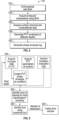
- Fig. 5 provides an example workflow for a fluid sampling advisor
- box 190 generally illustrates the process to create a continuous PVT phase envelope log obtained from the fluid chemical composition from mud gas data at the surface of a drill rig. Due to the necessity of transferring the chemical composition acquired at the surface to downhole in situ conditions, the phase envelope log acquired at from mud gas data may lack in accuracy. The accuracy of the results from the process of box 190 may thus be improved by using downhole fluid sampling or fluid identification tools to determine the fluid chemical composition under in situ conditions. The selection of the sampling or fluid identification point for the tool may be guided by the PVT phase envelope log and / or a combination of formation evaluation logs. For example, at step 200, promising hydrocarbon-bearing formations may be identified. After the fluid has been sufficiently identified to evaluate the benefits of a sample at step 202, a fluid sample is drawn from that formation at step 204.
- the downhole fluid sampling operation may then be configured in a way to deliver PVT properties such as the bubble point or the dew point for in situ conditions.
- PVT properties such as the bubble point or the dew point for in situ conditions.
- a pressure drawdown may be conducted at a given formation temperature and the fluid parameters such as fluid density, viscosity, refractive index, acoustic wave propagation velocity or similar may be monitored to identify a phase transition.
- the detection of such a phase transition may then be used to calibrate or validate the continuous PVT phase envelope log by comparing dew or bubble points (validation) or by adjusting the PVT phase envelope log (calibration).
- a PVT phase envelope log derived from mud gas data at the surface may indicate circumstances which are disadvantageous for the conduction of a downhole fluid sampling operation by a downhole tool.
- the phase envelope log may, at a particular depth, indicate the formation reservoir pressure being close to the bubble point, so that an excessive drawdown would precipitate asphaltenes from the liquid phase into the solid phase. Such asphaltenes may plug flow lines within the sampling device, which should be avoided to ensure a successful sampling operation.
- a PVT phase envelope log may thus be used to define a maximum drawdown possible to keep the subsurface fluid in a single phase.
Landscapes
- Life Sciences & Earth Sciences (AREA)
- Engineering & Computer Science (AREA)
- Geology (AREA)
- Mining & Mineral Resources (AREA)
- Physics & Mathematics (AREA)
- Environmental & Geological Engineering (AREA)
- Fluid Mechanics (AREA)
- General Life Sciences & Earth Sciences (AREA)
- Geochemistry & Mineralogy (AREA)
- Geophysics And Detection Of Objects (AREA)
Claims (15)
- Verfahren zum Erzeugen eines Phasenhüllkurvenbohrberichts, um eine unterirdische Formation zu kennzeichnen, die durch ein Bohrloch eines Schachts durchschnitten wird, das Verfahren umfassend:Bohren (122) des Bohrlochs mit einem Bohrstrang (16);Zirkulieren eines Bohrfluids in dem Bohrloch;Entnehmen (126) von mindestens zwei Fluidproben an der Oberfläche einer Bohranlage unter Verwendung von Oberflächenmessgeräten, jede Fluidprobe umfassend mindestens einen Anteil eines Fluids, das in der unterirdischen Formation enthalten ist, aus jeweils einer von mindestens zwei unterschiedlichen Tiefen in dem Bohrloch, gemessen entlang einer Schachttrajektorie;Erfassen (124), von einem Bohrlochinstrument, von mindestens einem jeweiligen PVT-Parameter, der einen in situ-Zustand der unterirdischen Formation in Bezug auf jede Fluidprobe angibt, wobei der mindestens eine jeweilige PVT-Parameter in Bezug auf jede Fluidprobe spezifisch für eine spezielle Bohrlochtiefe ist;Bestimmen (128) einer Phasenhüllkurve für jede jeweilige Fluidprobe unter Verwendung einer chemischen Zusammensetzung der Fluidprobe und des jeweiligen mindestens einen PVT-Parameters; undErstellen (130) eines kontinuierlichen Phasenhüllkurvenbohrberichts, der aus einer kontinuierlichen Reihe von Phasenhüllkurven besteht, unter Verwendung der bestimmten Phasenhüllkurven;wobei der Schritt des Erstellens des kontinuierlichen Phasenhüllkurvenbohrberichts erfolgt durch:(i) Anordnen der bestimmten Phasenhüllkurven gemäß der gemessenen Tiefe entlang der Schachttrajektorie; und(ii) Interpolieren zwischen zwei angrenzenden bestimmten Phasenhüllkurven gemäß der Tiefe, um Bereiche ohne Informationen über die Phasenhüllkurve auszufüllen.
- Verfahren nach Anspruch 1, wobei das Erfassen von mindestens einem jeweiligen PVT-Parameter mit Sensoren in einer Bohrgarnitur (20) durchgeführt wird.
- Verfahren nach Anspruch 1 oder 2, ferner umfassend ein Vergleichen des kontinuierlichen Phasenhüllkurvenbohrberichts mit in situ-Bohrlochmessungen, um Phasenhüllkurven für spezifische Bohrlochfluidproben und Testtiefen zu validieren.
- Verfahren nach Anspruch 1, 2 oder 3, ferner umfassend die Verwendung des kontinuierlichen Phasenhüllkurvenbohrberichts zum Identifizieren von Fluidräumen.
- Verfahren nach einem der vorstehenden Ansprüche, wobei jede Fluidprobe entnommen wird, während das Bohrloch durch den Bohrstrang gebohrt wird.
- Verfahren nach einem der vorstehenden Ansprüche, wobei der Schritt des Erstellens des kontinuierlichen Phasenhüllkurvenbohrberichts ferner ein Extrapolieren einer oder mehrerer Phasenhüllkurven aus den bestimmten Phasenhüllkurven gemäß der Tiefe umfasst, um einen Phasenhüllkurvenbohrbericht zu erweitern.
- Verfahren nach einem der vorstehenden Ansprüche, wobei der kontinuierliche Phasenhüllkurvenbohrbericht entlang der Schachttrajektorie angezeigt wird.
- Verfahren nach Anspruch 1, wobei der erfasste mindestens eine PVT-Parameter mindestens eines ist von: (i) Druck, (ii) Temperatur.
- Verfahren nach Anspruch 1, wobei die chemische Zusammensetzung jeder Fluidprobe aus mindestens einem von einem Gaschromatographen, einem Massenspektrometer und einer spektroskopischen Vorrichtung abgeleitet wird.
- Verfahren nach Anspruch 1, ferner umfassend ein Schätzen einer PVT-Eigenschaft aus dem kontinuierlichen Phasenhüllkurvenbohrbericht, die PVT-Eigenschaft umfassend mindestens eines von (i) Blasenpunkt, (ii) Taupunkt und (iii) Asphalten-Austrittspunkt.
- Verfahren nach einem der Ansprüche 1 bis 4, ferner umfassend die Verwendung von Bohrlochfluidproben und Fluididentifizierungswerkzeugen, um eine chemische Zusammensetzung und eine oder mehrere PVT-Eigenschaften einer oder der Bohrlochfluidprobe unter in situ-Bedingungen zu bestimmen, wobei die bestimmte eine oder die mehreren PVT-Eigenschaften der Bohrlochfluidprobe für mindestens eines verwendet wird/werden von: (i) Kalibrieren mindestens eines Anteils des kontinuierlichen Phasenhüllkurvenbohrberichts und (ii) Validieren mindestens eines Anteils des kontinuierlichen Phasenhüllkurvenbohrberichts.
- Verfahren nach Anspruch 1, ferner umfassend das Steuern einer Bohrlochvorrichtung unter Verwendung mindestens eines Anteils des kontinuierlichen Phasenhüllkurvenbohrberichts.
- Verfahren nach einem der vorstehenden Ansprüche, wobei das Oberflächenmessgerät ein Oberflächenschlammmessgerät umfasst.
- System zum Erzeugen eines Phasenhüllkurvenbohrberichts, um eine unterirdische Formation zu kennzeichnen, die durch ein Bohrloch eines Schachts durchschnitten wird, das System umfassend:einen Bohrstrang (16), der konfiguriert ist, um das Bohrloch zu bohren;ein Fluidprobenahmesystem (20, 30), das konfiguriert ist, um unter Verwendung von Oberflächenmessgeräten mindestens zwei Fluidproben an der Oberfläche einer Bohranlage zu entnehmen, jede Fluidprobe umfassend mindestens einen Anteil eines in der unterirdischen Formation enthaltenen Fluids aus einer jeweiligen von mindestens zwei unterschiedlichen Tiefen in dem Bohrloch, gemessen entlang einer Schachttrajektorie;ein Bohrlochinstrument, das konfiguriert ist, um mindestens einen jeweiligen PVT-Parameter zu erfassen, der einen in situ-Zustand der unterirdischen Formation in Bezug auf jede Fluidprobe angibt, wobei der mindestens eine jeweilige PVT-Parameter in Bezug auf jede Fluidprobe spezifisch für eine spezielle Bohrlochtiefe ist;einen Analysator für die chemische Zusammensetzung, der aus mindestens einem ausgewählt ist von: einem Gaschromatographen, einem Massenspektrometer und einem spektroskopischen Analysator, wobei der Analysator für die chemische Zusammensetzung konfiguriert ist, um eine chemische Zusammensetzung jeder Fluidprobe zu schätzen; undeinen Prozessor (60), der konfiguriert ist zum:- Bestimmen einer Phasenhüllkurve für jede jeweilige Fluidprobe unter Verwendung der chemischen Zusammensetzung der Fluidprobe und des jeweiligen mindestens einen PVT-Parameters; und- Erstellen eines kontinuierlichen Phasenhüllkurvenbohrberichts, der aus einer kontinuierlichen Reihe von Phasenhüllkurven besteht, unter Verwendung der bestimmten Phasenhüllkurven, durch (i) Anordnen der bestimmten Phasenhüllkurven gemäß der gemessenen Tiefe entlang der Schachttrajektorie; und (ii) Interpolieren zwischen zwei angrenzenden bestimmten Phasenhüllkurven gemäß der Tiefe, um Bereiche ohne Informationen über die Phasenhüllkurve auszufüllen.
- System nach Anspruch 14, wobei das Fluidprobenahmesystem (20, 30) ferner konfiguriert ist, um eine Bohrlochfluidprobe von einer Bohrlochposition zu entnehmen.
Applications Claiming Priority (2)
| Application Number | Priority Date | Filing Date | Title |
|---|---|---|---|
| US15/238,424 US10598010B2 (en) | 2016-08-16 | 2016-08-16 | Method for constructing a continuous PVT phase envelope log |
| PCT/US2017/047142 WO2018035222A1 (en) | 2016-08-16 | 2017-08-16 | Method for constructing a continuous pvt phase envelope log |
Publications (3)
| Publication Number | Publication Date |
|---|---|
| EP3500729A1 EP3500729A1 (de) | 2019-06-26 |
| EP3500729A4 EP3500729A4 (de) | 2020-04-15 |
| EP3500729B1 true EP3500729B1 (de) | 2025-06-04 |
Family
ID=61191391
Family Applications (1)
| Application Number | Title | Priority Date | Filing Date |
|---|---|---|---|
| EP17842055.0A Active EP3500729B1 (de) | 2016-08-16 | 2017-08-16 | Verfahren zur erstellung einer kontinuierlichen pvt-phasenhüllkurvenlogs |
Country Status (4)
| Country | Link |
|---|---|
| US (1) | US10598010B2 (de) |
| EP (1) | EP3500729B1 (de) |
| SA (1) | SA519401096B1 (de) |
| WO (1) | WO2018035222A1 (de) |
Families Citing this family (3)
| Publication number | Priority date | Publication date | Assignee | Title |
|---|---|---|---|---|
| US10738548B2 (en) * | 2016-01-29 | 2020-08-11 | Halliburton Energy Services, Inc. | Stochastic control method for mud circulation system |
| CA3116482C (en) * | 2020-06-12 | 2023-10-03 | Landmark Graphics Corporation | Reservoir fluid property modeling using machine learning |
| CN111855484B (zh) * | 2020-07-30 | 2022-05-20 | 西南石油大学 | 基于声电响应评价钻井液稳定泥页岩地层井壁能力的方法 |
Citations (2)
| Publication number | Priority date | Publication date | Assignee | Title |
|---|---|---|---|---|
| US20090151426A1 (en) * | 2007-12-17 | 2009-06-18 | Schlumberger Technology Corporation | High pressure and high temperature chromatography |
| EP3032026A1 (de) * | 2014-12-11 | 2016-06-15 | Services Pétroliers Schlumberger | Analyse eines reservoirs mittels flüssigkeitsanalyse |
Family Cites Families (12)
| Publication number | Priority date | Publication date | Assignee | Title |
|---|---|---|---|---|
| US6758090B2 (en) * | 1998-06-15 | 2004-07-06 | Schlumberger Technology Corporation | Method and apparatus for the detection of bubble point pressure |
| US7526953B2 (en) * | 2002-12-03 | 2009-05-05 | Schlumberger Technology Corporation | Methods and apparatus for the downhole characterization of formation fluids |
| US7398159B2 (en) * | 2005-01-11 | 2008-07-08 | Schlumberger Technology Corporation | System and methods of deriving differential fluid properties of downhole fluids |
| EP2304174A4 (de) * | 2008-05-22 | 2015-09-23 | Schlumberger Technology Bv | Bohrlochmessung von formationskennwerten beim bohren |
| US8109334B2 (en) | 2009-07-13 | 2012-02-07 | Schlumberger Technology Corporation | Sampling and evaluation of subterranean formation fluid |
| WO2011007268A1 (en) * | 2009-07-13 | 2011-01-20 | Schlumberger Canada Limited | Methods for characterization of petroleum fluid and application thereof |
| US8380446B2 (en) | 2010-06-14 | 2013-02-19 | Schlumberger Technology Corporation | System and method for determining the phase envelope of a gas condensate |
| US9416647B2 (en) | 2012-01-31 | 2016-08-16 | Schlumberger Technology Corporation | Methods and apparatus for characterization of hydrocarbon reservoirs |
| US20160040533A1 (en) * | 2013-03-14 | 2016-02-11 | Schlumberger Technology Corporation | Pressure Volume Temperature System |
| US20170067322A1 (en) | 2014-03-12 | 2017-03-09 | Landmark Graphic Corporation | Efficient and robust compositional reservoir simulation using a fast phase envelope |
| US10024755B2 (en) * | 2014-09-30 | 2018-07-17 | Schlumberger Technology Corporation | Systems and methods for sample characterization |
| EP3488077B1 (de) * | 2016-08-11 | 2024-04-17 | Halliburton Energy Services, Inc. | Flüssigkeitscharakterisierung und phasenhüllkurvenvorhersage aus einem werkzeug zur entnahme von bohrlochflüssigkeitsproben |
-
2016
- 2016-08-16 US US15/238,424 patent/US10598010B2/en active Active
-
2017
- 2017-08-16 EP EP17842055.0A patent/EP3500729B1/de active Active
- 2017-08-16 WO PCT/US2017/047142 patent/WO2018035222A1/en not_active Ceased
-
2019
- 2019-02-12 SA SA519401096A patent/SA519401096B1/ar unknown
Patent Citations (2)
| Publication number | Priority date | Publication date | Assignee | Title |
|---|---|---|---|---|
| US20090151426A1 (en) * | 2007-12-17 | 2009-06-18 | Schlumberger Technology Corporation | High pressure and high temperature chromatography |
| EP3032026A1 (de) * | 2014-12-11 | 2016-06-15 | Services Pétroliers Schlumberger | Analyse eines reservoirs mittels flüssigkeitsanalyse |
Non-Patent Citations (1)
| Title |
|---|
| J ERZINGER ET AL: "Real-time mud gas logging and sampling during drilling", GEOFLUIDS, vol. 6, 20 June 2006 (2006-06-20), pages 225 - 233, XP055051713, DOI: 10.1111/j.1468-8123.2006.00152.x * |
Also Published As
| Publication number | Publication date |
|---|---|
| US10598010B2 (en) | 2020-03-24 |
| SA519401096B1 (ar) | 2023-02-07 |
| WO2018035222A8 (en) | 2019-03-07 |
| EP3500729A4 (de) | 2020-04-15 |
| WO2018035222A1 (en) | 2018-02-22 |
| EP3500729A1 (de) | 2019-06-26 |
| US20180051558A1 (en) | 2018-02-22 |
Similar Documents
| Publication | Publication Date | Title |
|---|---|---|
| US11927716B2 (en) | Predicting contamination and clean fluid properties from downhole and wellsite gas chromatograms | |
| CN108713089B (zh) | 基于钻孔流体和钻探录井估计地层性质 | |
| US9341557B2 (en) | Method and system for permeability calculation using production logs for horizontal wells, using a downhole tool | |
| US10378349B2 (en) | Methods of plotting advanced logging information | |
| US9482089B2 (en) | Receiving and measuring expelled gas from a core sample | |
| US10690642B2 (en) | Method for automatically generating a fluid property log derived from drilling fluid gas data | |
| EP3500729B1 (de) | Verfahren zur erstellung einer kontinuierlichen pvt-phasenhüllkurvenlogs | |
| US8813554B2 (en) | Methods and apparatus to estimate fluid component volumes | |
| US12116889B2 (en) | Single side determination of a first formation fluid-second formation fluid boundary | |
| US10066482B2 (en) | Method and systems for integrating downhole fluid data with surface mud-gas data | |
| US20170167256A1 (en) | Determining Water Salinity and Water-Filled Porosity of a Formation | |
| US20230349286A1 (en) | Geologic formation characterization | |
| US20210381363A1 (en) | Relative permeability estimation methods and systems employing downhole pressure transient analysis, saturation analysis, and porosity analysis | |
| US10830040B2 (en) | Field-level analysis of downhole operation logs | |
| Torres-Verdín et al. | History matching of multiphase-flow formation-tester measurements acquired with focused-sampling probes in deviated wells | |
| US20250012183A1 (en) | Fluid property estimation based on electromagnetic measurements | |
| US20250122796A1 (en) | Method for deep well testing and permeability determination in different directions |
Legal Events
| Date | Code | Title | Description |
|---|---|---|---|
| STAA | Information on the status of an ep patent application or granted ep patent |
Free format text: STATUS: THE INTERNATIONAL PUBLICATION HAS BEEN MADE |
|
| PUAI | Public reference made under article 153(3) epc to a published international application that has entered the european phase |
Free format text: ORIGINAL CODE: 0009012 |
|
| STAA | Information on the status of an ep patent application or granted ep patent |
Free format text: STATUS: REQUEST FOR EXAMINATION WAS MADE |
|
| 17P | Request for examination filed |
Effective date: 20190313 |
|
| AK | Designated contracting states |
Kind code of ref document: A1 Designated state(s): AL AT BE BG CH CY CZ DE DK EE ES FI FR GB GR HR HU IE IS IT LI LT LU LV MC MK MT NL NO PL PT RO RS SE SI SK SM TR |
|
| AX | Request for extension of the european patent |
Extension state: BA ME |
|
| RIN1 | Information on inventor provided before grant (corrected) |
Inventor name: RITZMANN, NICKLAS, J. Inventor name: ERDMANN, SVENJA Inventor name: MOHNKE, OLIVER Inventor name: THERN, HOLGER, F. Inventor name: WESSLING, STEFAN |
|
| DAV | Request for validation of the european patent (deleted) | ||
| DAX | Request for extension of the european patent (deleted) | ||
| A4 | Supplementary search report drawn up and despatched |
Effective date: 20200317 |
|
| RIC1 | Information provided on ipc code assigned before grant |
Ipc: E21B 49/08 20060101AFI20200311BHEP Ipc: E21B 47/00 20120101ALI20200311BHEP |
|
| STAA | Information on the status of an ep patent application or granted ep patent |
Free format text: STATUS: EXAMINATION IS IN PROGRESS |
|
| 17Q | First examination report despatched |
Effective date: 20201120 |
|
| P01 | Opt-out of the competence of the unified patent court (upc) registered |
Effective date: 20230526 |
|
| GRAP | Despatch of communication of intention to grant a patent |
Free format text: ORIGINAL CODE: EPIDOSNIGR1 |
|
| STAA | Information on the status of an ep patent application or granted ep patent |
Free format text: STATUS: GRANT OF PATENT IS INTENDED |
|
| INTG | Intention to grant announced |
Effective date: 20250321 |
|
| GRAS | Grant fee paid |
Free format text: ORIGINAL CODE: EPIDOSNIGR3 |
|
| GRAA | (expected) grant |
Free format text: ORIGINAL CODE: 0009210 |
|
| STAA | Information on the status of an ep patent application or granted ep patent |
Free format text: STATUS: THE PATENT HAS BEEN GRANTED |
|
| AK | Designated contracting states |
Kind code of ref document: B1 Designated state(s): AL AT BE BG CH CY CZ DE DK EE ES FI FR GB GR HR HU IE IS IT LI LT LU LV MC MK MT NL NO PL PT RO RS SE SI SK SM TR |
|
| RAP3 | Party data changed (applicant data changed or rights of an application transferred) |
Owner name: BAKER HUGHES HOLDINGS LLC |
|
| REG | Reference to a national code |
Ref country code: GB Ref legal event code: FG4D |
|
| REG | Reference to a national code |
Ref country code: CH Ref legal event code: EP |
|
| REG | Reference to a national code |
Ref country code: DE Ref legal event code: R096 Ref document number: 602017089806 Country of ref document: DE |
|
| REG | Reference to a national code |
Ref country code: IE Ref legal event code: FG4D |
|
| REG | Reference to a national code |
Ref country code: NL Ref legal event code: MP Effective date: 20250604 |
|
| PG25 | Lapsed in a contracting state [announced via postgrant information from national office to epo] |
Ref country code: FI Free format text: LAPSE BECAUSE OF FAILURE TO SUBMIT A TRANSLATION OF THE DESCRIPTION OR TO PAY THE FEE WITHIN THE PRESCRIBED TIME-LIMIT Effective date: 20250604 Ref country code: ES Free format text: LAPSE BECAUSE OF FAILURE TO SUBMIT A TRANSLATION OF THE DESCRIPTION OR TO PAY THE FEE WITHIN THE PRESCRIBED TIME-LIMIT Effective date: 20250604 |
|
| REG | Reference to a national code |
Ref country code: LT Ref legal event code: MG9D |
|
| PG25 | Lapsed in a contracting state [announced via postgrant information from national office to epo] |
Ref country code: GR Free format text: LAPSE BECAUSE OF FAILURE TO SUBMIT A TRANSLATION OF THE DESCRIPTION OR TO PAY THE FEE WITHIN THE PRESCRIBED TIME-LIMIT Effective date: 20250905 |
|
| PGFP | Annual fee paid to national office [announced via postgrant information from national office to epo] |
Ref country code: NO Payment date: 20250725 Year of fee payment: 9 |
|
| PG25 | Lapsed in a contracting state [announced via postgrant information from national office to epo] |
Ref country code: PL Free format text: LAPSE BECAUSE OF FAILURE TO SUBMIT A TRANSLATION OF THE DESCRIPTION OR TO PAY THE FEE WITHIN THE PRESCRIBED TIME-LIMIT Effective date: 20250604 |
|
| PG25 | Lapsed in a contracting state [announced via postgrant information from national office to epo] |
Ref country code: BG Free format text: LAPSE BECAUSE OF FAILURE TO SUBMIT A TRANSLATION OF THE DESCRIPTION OR TO PAY THE FEE WITHIN THE PRESCRIBED TIME-LIMIT Effective date: 20250604 |
|
| PGFP | Annual fee paid to national office [announced via postgrant information from national office to epo] |
Ref country code: GB Payment date: 20250725 Year of fee payment: 9 |
|
| PG25 | Lapsed in a contracting state [announced via postgrant information from national office to epo] |
Ref country code: HR Free format text: LAPSE BECAUSE OF FAILURE TO SUBMIT A TRANSLATION OF THE DESCRIPTION OR TO PAY THE FEE WITHIN THE PRESCRIBED TIME-LIMIT Effective date: 20250604 |
|
| PG25 | Lapsed in a contracting state [announced via postgrant information from national office to epo] |
Ref country code: RS Free format text: LAPSE BECAUSE OF FAILURE TO SUBMIT A TRANSLATION OF THE DESCRIPTION OR TO PAY THE FEE WITHIN THE PRESCRIBED TIME-LIMIT Effective date: 20250904 |
|
| PG25 | Lapsed in a contracting state [announced via postgrant information from national office to epo] |
Ref country code: LV Free format text: LAPSE BECAUSE OF FAILURE TO SUBMIT A TRANSLATION OF THE DESCRIPTION OR TO PAY THE FEE WITHIN THE PRESCRIBED TIME-LIMIT Effective date: 20250604 |
|
| PG25 | Lapsed in a contracting state [announced via postgrant information from national office to epo] |
Ref country code: NL Free format text: LAPSE BECAUSE OF FAILURE TO SUBMIT A TRANSLATION OF THE DESCRIPTION OR TO PAY THE FEE WITHIN THE PRESCRIBED TIME-LIMIT Effective date: 20250604 |
|
| PG25 | Lapsed in a contracting state [announced via postgrant information from national office to epo] |
Ref country code: PT Free format text: LAPSE BECAUSE OF FAILURE TO SUBMIT A TRANSLATION OF THE DESCRIPTION OR TO PAY THE FEE WITHIN THE PRESCRIBED TIME-LIMIT Effective date: 20251006 |
|
| REG | Reference to a national code |
Ref country code: AT Ref legal event code: MK05 Ref document number: 1800495 Country of ref document: AT Kind code of ref document: T Effective date: 20250604 |
|
| PG25 | Lapsed in a contracting state [announced via postgrant information from national office to epo] |
Ref country code: IS Free format text: LAPSE BECAUSE OF FAILURE TO SUBMIT A TRANSLATION OF THE DESCRIPTION OR TO PAY THE FEE WITHIN THE PRESCRIBED TIME-LIMIT Effective date: 20251004 |
|
| PG25 | Lapsed in a contracting state [announced via postgrant information from national office to epo] |
Ref country code: AT Free format text: LAPSE BECAUSE OF FAILURE TO SUBMIT A TRANSLATION OF THE DESCRIPTION OR TO PAY THE FEE WITHIN THE PRESCRIBED TIME-LIMIT Effective date: 20250604 Ref country code: SM Free format text: LAPSE BECAUSE OF FAILURE TO SUBMIT A TRANSLATION OF THE DESCRIPTION OR TO PAY THE FEE WITHIN THE PRESCRIBED TIME-LIMIT Effective date: 20250604 |
|
| PG25 | Lapsed in a contracting state [announced via postgrant information from national office to epo] |
Ref country code: CZ Free format text: LAPSE BECAUSE OF FAILURE TO SUBMIT A TRANSLATION OF THE DESCRIPTION OR TO PAY THE FEE WITHIN THE PRESCRIBED TIME-LIMIT Effective date: 20250604 |
|
| PG25 | Lapsed in a contracting state [announced via postgrant information from national office to epo] |
Ref country code: EE Free format text: LAPSE BECAUSE OF FAILURE TO SUBMIT A TRANSLATION OF THE DESCRIPTION OR TO PAY THE FEE WITHIN THE PRESCRIBED TIME-LIMIT Effective date: 20250604 |
|
| PG25 | Lapsed in a contracting state [announced via postgrant information from national office to epo] |
Ref country code: RO Free format text: LAPSE BECAUSE OF FAILURE TO SUBMIT A TRANSLATION OF THE DESCRIPTION OR TO PAY THE FEE WITHIN THE PRESCRIBED TIME-LIMIT Effective date: 20250604 Ref country code: SK Free format text: LAPSE BECAUSE OF FAILURE TO SUBMIT A TRANSLATION OF THE DESCRIPTION OR TO PAY THE FEE WITHIN THE PRESCRIBED TIME-LIMIT Effective date: 20250604 |
|
| PG25 | Lapsed in a contracting state [announced via postgrant information from national office to epo] |
Ref country code: IT Free format text: LAPSE BECAUSE OF FAILURE TO SUBMIT A TRANSLATION OF THE DESCRIPTION OR TO PAY THE FEE WITHIN THE PRESCRIBED TIME-LIMIT Effective date: 20250604 |
|
| REG | Reference to a national code |
Ref country code: CH Ref legal event code: H13 Free format text: ST27 STATUS EVENT CODE: U-0-0-H10-H13 (AS PROVIDED BY THE NATIONAL OFFICE) Effective date: 20260324 |