EP3500518B1 - System for transporting and storing a liquid and for transporting said liquid from the container to a destination outside of the container - Google Patents
System for transporting and storing a liquid and for transporting said liquid from the container to a destination outside of the container Download PDFInfo
- Publication number
- EP3500518B1 EP3500518B1 EP17754845.0A EP17754845A EP3500518B1 EP 3500518 B1 EP3500518 B1 EP 3500518B1 EP 17754845 A EP17754845 A EP 17754845A EP 3500518 B1 EP3500518 B1 EP 3500518B1
- Authority
- EP
- European Patent Office
- Prior art keywords
- bore
- plug
- hooking
- male probe
- container
- Prior art date
- Legal status (The legal status is an assumption and is not a legal conclusion. Google has not performed a legal analysis and makes no representation as to the accuracy of the status listed.)
- Active
Links
- 239000007788 liquid Substances 0.000 title claims description 16
- 239000000523 sample Substances 0.000 claims description 31
- 238000007789 sealing Methods 0.000 claims description 5
- 239000012530 fluid Substances 0.000 claims description 4
- 230000000284 resting effect Effects 0.000 claims 1
- 238000001746 injection moulding Methods 0.000 description 1
- 230000007246 mechanism Effects 0.000 description 1
Images


Classifications
-
- B—PERFORMING OPERATIONS; TRANSPORTING
- B67—OPENING, CLOSING OR CLEANING BOTTLES, JARS OR SIMILAR CONTAINERS; LIQUID HANDLING
- B67D—DISPENSING, DELIVERING OR TRANSFERRING LIQUIDS, NOT OTHERWISE PROVIDED FOR
- B67D7/00—Apparatus or devices for transferring liquids from bulk storage containers or reservoirs into vehicles or into portable containers, e.g. for retail sale purposes
- B67D7/02—Apparatus or devices for transferring liquids from bulk storage containers or reservoirs into vehicles or into portable containers, e.g. for retail sale purposes for transferring liquids other than fuel or lubricants
- B67D7/0288—Container connection means
- B67D7/0294—Combined with valves
Landscapes
- Engineering & Computer Science (AREA)
- Mechanical Engineering (AREA)
- Closures For Containers (AREA)
Description
- The present invention relates to a system for transporting and storing a liquid and for transporting said liquid from the container to a destination outside of the container. The system is in particular suitable for safe transfer of liquids according to a 'closed transfer system', in particular to transfer crop protection products into a sprayer.
- Such a system according to the preamble of claim 1 is well known and commercially available from the applicant. It is described in
WO 99/05446 WO 94/10081 WO 2011/096811 . - The aim of the invention is to provide such a system suitable for large diameter bores, in particular exceeding 30mm.
- It has been found that when the known cap assembly is scaled up to a bore having a diameter exceeding 30mm, e.g. to be assembled onto a container comprising a relatively large inlet opening, in particular exceeding 30mm, in particular industry standard containers with 63mm closures, unintentional release of the plug occurs. In order to ensure a closed transfer system, the cap assembly is to be assembled onto the container straight after the filling of the container. Hereafter, the containers are transported to the site where the liquid is to be used. During transport there is a risk of dropping such a container filled with liquid. As the container is closed, liquid sloshing in the container, e.g. as a result of dropping, causes a hydrodynamic load exerted onto the plug of the cap assembly, and hence increases the risk of unintentional release of the plug.
- The invention aims to provide a system suitable for bores comprising a diameter exceeding 30mm.
- This aim is achieved in that a seal cover is provided over the bore, essentially parallel to the plug, which serves to close off the bore airtight. Such an airtight seal cover over the bore, parallel to the plug, counteracts possible hydrodynamic loads caused by sloshing and hence the risk of unintentional release of the plug is significantly reduced.
- Advantageously, the bore is large, e.g. having a diameter exceeding 30mm, in particular 45 mm, in particular 60mm or even larger.
- In a preferred embodiment, the inner wall of the cylindrical body further comprises a seal cover seat at an end adjacent the insert opening, extending around the bore, for a seal cover which serves to close off the bore airtight, and the essentially cylindrical body comprising a seal cover abutment surface for the seal cover, the seal cover abutment surface extending radially adjacent the insert opening,
the seal cover being provided with a sealing system with at least one radially deformable seal element adapted to releasably engage with the seal cover seat,
the seal cover being designed such that in a transfer position the seal cover abuts against the seal cover abutment surface and the seal elements abut against the seal cover seat, thereby covering the insert opening airtight. - The invention is further elucidated in relation to the drawings, in which:
-
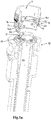
Fig. 1a is a perspective view of a system according to the invention comprising a portion of the container, the cap assembly and part of the coupler assembly, wherein the plug is in a first position; -
Fig. 1b is a perspective view of the system offig. 1a , wherein the coupler assembly has moved towards the plug, the plug still being in a first position; -
Fig. 1c is a perspective view of the system offig. 1a , wherein the male probe of the coupler assembly has been connected to a female part of the cap assembly, wherein the plug is in a fourth position; -
Fig. 2 shows a partly open perspective view of a cap assembly according to the invention; -
Fig. 3 shows a view of the inside of the cap assembly offig. 2 cut in halves; -
Fig. 4 shows a perspective view of the inside of a cap assembly and a neck portion of a container cut in halves; -
Fig. 5 shows a cap assembly including a plug in a perspective view; -
Fig. 6 shows an embodiment of a seal cover according to the invention. -
Figs. 1a-1c andfigs. 2-6 show different views and details of a similar embodiment of a system of the invention. Same parts are given same reference numerals. - In
figs. 1a-1c , an entire system for transporting and storing a liquid and for transporting said liquid from the container to a destination outside of the container is shown. The system comprises: - a container for transporting and storing a liquid, comprising a container body provided with a
neck portion 2; - a
cap assembly 10 secured on the neck portion for fluidly-tight closing the container body; - a
coupler assembly 30 configured to be mechanically coupled to thecap assembly 10 so as to achieve a coupled configuration for a liquid connection to and/ or from the container, comprising amale probe 31 to be connected to afemale part 11 of the cap assembly. - In particular, the
neck portion 2 surrounds aninlet opening 3, in particular an inlet opening having a diameter exceeding 30mm, in particular 45 mm, in particular 60mm or even larger. - The
cap assembly 10, shown in other views infigs. 2-5 , comprises thefemale part 11 and aplug 20, the female part having an essentially cylindrical body comprising two concentric interconnectedcylindrical walls cylindrical slit 14 having an open end 14a and a closedend 14b where the outercylindrical wall 13 is connected to the innercylindrical wall 12. The slit is adapted to receive, at the open end thereof, theneck portion 2 of the container body to provide a fluid-tight closure around the neck portion. - In the shown embodiment, , the container is positioned with its neck portion downwards, and hence the open end of the cylindrical slit corresponds to top end and the closed end to the bottom end. It is also conceivable that the container is positioned with its neck portion upwards, allowing the the cap assembly to be positioned over the neck portion.
- In the shown embodiment, a
seal ring 15 is provided at the closed bottom end of thecylindrical slit 14b to assist the fluid-tight closure of anupper end 2a of theneck portion 2 of the container body by thefemale part 11 of the cap assembly. - In the shown embodiment, the
cylindrical slit 14 comprises a slit engagement surface 14c, here provided at the outer cylindrical wall. It is also conceivable that the slit engagement surface is provided at the inner cylindrical wall, or at both walls. The slit engagement surface is adapted to engage with a correspondingneck engagement surface 2c at theneck portion 2 of the container body to provide a fluid-tight closure around the neck portion. The slit engagement surface and corresponding neck engagement surface are here formed by cooperating screw thread. Other engagement mechanisms, e.g. involving a rim and a recess, are also conceivable. - In the shown embodiment, the outer
cylindrical wall 13 is provided with a tamper-evident ring 19, here extending as a continuation of the outer cylindrical wall. This tamper-evident ring has to be removed to be able to remove the cap assembly from the neck portion of the container body. Accordingly, one can determine from the status of the tamper-evident ring whether the cap assembly has been removed from the container or not. - It is noted that in
figs. 2 and3 the innercylindrical wall 12 comprises ashallow slit 12c atend 12a adjacent the plug opening 18. In the shown embodiment this is provided for constructive purposes relating to injection moulding. - The inner wall of the
cylindrical body 12 defines anaxial bore 16 extending from aninsert opening 17 for the male probe through the body to anopposed plug opening 18. The openings of the shown embodiment are of similar dimension. The insert opening and plug opening are provided at opposed ends of the body. When thecap assembly 10 is engaged with theneck portion 2 of the container body, the inlet opening 3 is within theaxial bore 16. - The inner wall of the
cylindrical body 12 comprises aseat 12b adjacent theplug opening 18, extending around thebore 16, for theplug 20 which serves to close off the bore fluid-tight. - This plug and its operation has extensively been described and disclosed in
WO99/05446 seat 12b comprises ashoulder 12d, facing towards the insert opening. Theplug 20 is provided with a hooking system with multiple elastic hookingparts surfaces 21a", 21e". As visible infig. 1a , at least one of the hooking parts rests in a first position with its hooking surface against the shoulder, in which first position theplug 20 closes off the bore and hence fluidly-tight closes the plug opening of the container body. - The
coupler assembly 30 has amale probe 31 with a head and arecess 33 located behind the head for receiving at least one of the hooking parts of the plug when the male probe is inserted into the bore, in particular at least one ofsurfaces 21a', 21b', 21c', 21d', 21e' of the hooking parts, so that the plug connects with the male probe. Radially next to the at least one of the hooking parts in its first position there is aspace 22 between the hookingpart female part 11. - The at least one hooking part is designed such that - when the male is inserted into the bore - the
head 32 of the male probe pushes the hooking part from its first position into thisspace 22 to a second position which is located radially further outward compared with the first position, in which second position the plug still closes off the bore and hence fluidly-tight closes the plug opening of the container body. - The at least one hooking part is further designed such that at least one of the hooking parts, after axially passing the
head 32 of the male probe towards a bottom of the container body, springs elastically inward to a third position and falls into therecess 33 of the male probe while contact between the hooking surface and the shoulder is maintained and while the contact between hooking surface and shoulder is maintained the plug still closes off the bore and hence fluidly-tight closes the plug opening of the container body. - The
recess 33 in the male probe is such that a radial space is present between the hookingpart 21, located in its third position, and themale probe 31, in such a way that inserting themale probe 31 further into thebore 16 towards a bottom of the container body causes the hookingpart 21 to pass theshoulder 22 in the bore, the hooking part moves under the influence of a force exerted by the shoulder of the bore on the hooking part to a fourth position, as visible inFig. 1c , which is located further inward in therecess 33 compared with the third position, such that the plug engaged with the male probe opens the bore and hence allows fluid to pass from and to the container body. - Advantageously, the connector assembly has been designed such that the
plug 20 is free of thebore 16 when the male probe has been inserted fully into the bore, with at least one of the hookingparts 21 of theplug 20 springing back elastically from the fourth position to the third position when it comes out of the bore. - The shown male probe has an internal
axial passage 101 for passage of the fluid in which one ormore ports 105 are provided, each extending from the outer surface of the male probe to an outlet in the axial passage. - According to the present invention, a
seal cover 45 is provided over thebore 16, essentially parallel to theplug 20, which serves to close off the bore airtight. In particular, the shownseal cover 45 comprises aseal surface 40 extending across and parallel to theinsert opening 17. Theseal cover 45 is shown in detail infig. 6 . Alternative configurations of a seal cover are also conceivable as long as the bore is closed off airtight. For example a topseal or the like can be applied as well. - In the shown embodiment, the
inner wall 12 of the cylindrical body further comprises aseal cover seat 12f at anend 12e adjacent theinsert opening 17, extending around thebore 16, for theseal cover 45. Further, in the shown embodiment, the essentially cylindrical body comprises a sealcover abutment surface 12h for the seal cover, the seal cover abutment surface extending radially adjacent the insert opening. - The seal cover is here provided with a sealing system with at least one radially
deformable seal element 41 adapted to releasably engage with theseal cover seat 12f, here is a radially expandable and compressible ring-shaped collar extending perpendicular to the sealing surface of the seal cover. The seal cover is designed such that in a transfer position the seal cover abuts against the sealcover abutment surface 12h and the seal elements abut against the seal cover seat, thereby covering the insert opening airtight. - Furthermore, in the shown embodiment, the seal cover is provided with a tamper-
evident tear ring 42 extending around the essentially cylindrical body, which has to be removed prior to the removal of the seal cover. In this embodiment, the tamperevident ring 42 comprises arib 42a engaging below a thickened end rim 12g of theinner wall 12
Claims (10)
- System for transporting and storing a liquid and for transporting said liquid from the container to a destination outside of the container, the system comprising:• a container for transporting and storing a liquid, comprising a container body provided with a neck portion (2);• a cap assembly (10) secured on the neck portion for fluidly-tight closing the container body;• a coupler assembly (30) configured to be mechanically coupled to the cap assembly (10) so as to achieve a coupled configuration for a liquid connection to and/ or from the container, comprising a male probe (31) to be connected to a female part (11) of the cap assembly;wherein the cap assembly (10) comprises the female part (11) and a plug (20), the female part having an essentially cylindrical body comprising two concentric interconnected cylindrical walls (12, 13) defining there between a cylindrical slit (14) having an open end (14a) and a closed end (14b) where the outer cylindrical wall (13) is connected to the inner cylindrical wall (12), the slit being adapted to receive the neck portion (2) of the container body to provide a fluid-tight closure around the neck portion;
the inner wall of the cylindrical body (12) defining an axial bore (16) extending from an insert opening (17) for the male probe through the body to an opposed plug opening (18) at opposed ends of the body;
the inner wall of the cylindrical body (12) comprising a seat (12b) adjacent the plug opening (18), extending around the bore (16), for the plug (20) which serves to close off the bore fluid-tight;
wherein the bore of the female part between the insert opening (17) and the seat (12b) comprises a shoulder (12d), facing towards the insert opening, and the plug (20) is provided with a hooking system with multiple elastic hooking parts (21a, 21b, 21c, 21d, 21e) with corresponding hooking surfaces (21a", 21e"), at least one of the hooking parts resting in a first position with its hooking surface against the shoulder (fig. 1a), in which first position the plug (20) closes off the bore and hence fluidly-tight closes the plug opening of the container body;
wherein the coupler assembly (30) has a male probe (31) with a head and a recess (33) located behind the head for receiving at least one of the hooking parts of the plug when the male probe is inserted into the bore, so that the plug connects with the male probe,
wherein radially next to the at least one of the hooking parts in its first position there is a space (22) between the hooking part (21a, 21b, 21c, 21d, 21e) and the female part (11),
wherein the at least one hooking part is designed such that - when the male is inserted into the bore - the head (32) of the male probe pushes the hooking part from its first position into this space (22) to a second position which is located radially further outward compared with the first position, in which second position the plug still closes off the bore and hence fluidly-tight closes the plug opening of the container body;
and such that at least one of the hooking parts, after axially passing the head (32) of the male probe towards a bottom of the container body, springs elastically inward to a third position and falls into the recess (33) of the male probe while contact between the hooking surface and the shoulder is maintained and while the contact between hooking surface and shoulder is maintained the plug still closes off the bore and hence fluidly-tight closes the plug opening of the container body;
wherein the recess (33) in the male probe is such that a radial space is present between the hooking part (21), located in its third position, and the male probe (31), in such a way that inserting the male probe (31) further into the bore (16) towards a bottom of the container body causes the hooking part (21) to pass the shoulder (22) in the bore, the hooking part moves under the influence of a force exerted by the shoulder of the bore on the hooking part to a fourth position (Fig. 1c) which is located further inward in the recess (33) compared with the third position, such that the plug engaged with the male probe opens the bore and hence allows fluid to pass from and to the container body;
characterized in that a seal cover (45) is provided over the bore (16), essentially parallel to the plug (20), which serves to close off the bore airtight. - System according to claim 1, in which the seal cover (45) comprises a seal surface (40) extending across and parallel to the insert opening (17).
- System according to claim 1 or 2, wherein the inner wall (12) of the cylindrical body further comprises a seal cover seat (12f) at an end (12e) adjacent the insert opening (17), extending around the bore (16), for the seal cover (45),
the seal cover being provided with a sealing system with at least one radially deformable seal element (41) adapted to releasably engage with the seal cover seat (12f). - System according to one or more of the preceding claims, in which the at least one radially deformable seal element is a radially expandable and compressible ring-shaped collar extending perpendicular to the sealing surface of the seal cover.
- System according to one or more of the preceding claims, wherein the seal cover is provided with a tamper-evident tear ring (42) extending around the essentially cylindrical body.
- System according to one or more of the preceding claims, wherein the outer cylindrical wall (13) being provided with a tamper-evident ring (19), preferably extending as a continuation of the outer cylindrical wall.
- System according to one or more of the preceding claims, wherein a seal ring (15) is provided at the closed end of the cylindrical slit (14b) to assist the fluid-tight closure of an upper end (2a) of the neck portion (2) of the container body by the female part (11) of the cap assembly.
- System according to one or more of the preceding claims, wherein the cylindrical slit (14) comprising a slit engagement surface (14c) adapted to engage with a corresponding neck engagement surface (2c) at the neck portion (2) of the container body to provide a fluid-tight closure around the neck portion.
- System according to one or more of the preceding claims, wherein the connector assembly has been designed such that the plug (20) is free of the bore (16) when the male probe has been inserted fully into the bore, with at least one of the hooking parts (21) of the plug (20) springing back elastically from the fourth position to the third position when it comes out of the bore.
- System according to one or more of the preceding claims, wherein the male probe has an internal axial passage (101) for passage of the fluid in which one or more ports (105) are provided, each extending from the outer surface of the male probe to an outlet in the axial passage.
Priority Applications (1)
| Application Number | Priority Date | Filing Date | Title |
|---|---|---|---|
| PL17754845T PL3500518T3 (en) | 2016-08-18 | 2017-08-17 | System for transporting and storing a liquid and for transporting said liquid from the container to a destination outside of the container |
Applications Claiming Priority (2)
| Application Number | Priority Date | Filing Date | Title |
|---|---|---|---|
| NL2017331A NL2017331B1 (en) | 2016-08-18 | 2016-08-18 | System for transporting and storing a liquid and for transporting said liquid from the container to a destination outside of the container |
| PCT/NL2017/050540 WO2018034567A1 (en) | 2016-08-18 | 2017-08-17 | System for transporting and storing a liquid and for transporting said liquid from the container to a destination outside of the container |
Publications (2)
| Publication Number | Publication Date |
|---|---|
| EP3500518A1 EP3500518A1 (en) | 2019-06-26 |
| EP3500518B1 true EP3500518B1 (en) | 2020-10-21 |
Family
ID=57208338
Family Applications (1)
| Application Number | Title | Priority Date | Filing Date |
|---|---|---|---|
| EP17754845.0A Active EP3500518B1 (en) | 2016-08-18 | 2017-08-17 | System for transporting and storing a liquid and for transporting said liquid from the container to a destination outside of the container |
Country Status (9)
| Country | Link |
|---|---|
| US (1) | US10526194B2 (en) |
| EP (1) | EP3500518B1 (en) |
| CN (1) | CN209668749U (en) |
| BR (1) | BR112019000999B1 (en) |
| DK (1) | DK3500518T3 (en) |
| ES (1) | ES2834012T3 (en) |
| NL (1) | NL2017331B1 (en) |
| PL (1) | PL3500518T3 (en) |
| WO (1) | WO2018034567A1 (en) |
Families Citing this family (5)
| Publication number | Priority date | Publication date | Assignee | Title |
|---|---|---|---|---|
| US11220379B2 (en) | 2019-05-23 | 2022-01-11 | Ecolab Usa Inc. | Dispensing system |
| NL2024517B1 (en) | 2019-12-19 | 2021-09-02 | Scholle Ipn Ip Bv | A system for transporting and storing a liquid |
| FR3108316B1 (en) | 2020-03-23 | 2022-04-01 | United Caps France | CLOSING PLUG FOR CONTAINER WITH THREADED NECK AND SUITABLE FOR USE IN A CLOSED TRANSFER SYSTEM |
| US11673727B2 (en) * | 2021-03-03 | 2023-06-13 | Scholle Ipn Corporation | Dispensing system for a flexible bag, flexible bag assembly |
| WO2023002029A1 (en) | 2021-07-22 | 2023-01-26 | Basf Se | Safety closing device |
Family Cites Families (22)
| Publication number | Priority date | Publication date | Assignee | Title |
|---|---|---|---|---|
| US4375864A (en) * | 1980-07-21 | 1983-03-08 | Scholle Corporation | Container for holding and dispensing fluid |
| USRE32354E (en) * | 1980-07-21 | 1987-02-17 | Scholle Corporation | Container for holding and dispensing fluid |
| US4445551A (en) * | 1981-11-09 | 1984-05-01 | Bond Curtis J | Quick-disconnect coupling and valve assembly |
| US4708260A (en) * | 1984-10-26 | 1987-11-24 | Kiwi Coders Corporation | Hydraulic coupling comprising a sealed closure and connection fitting for a flexible container |
| DE8708058U1 (en) | 1987-06-06 | 1987-09-10 | Schroeder, Ulrich, 5160 Dueren, De | |
| US5222530A (en) * | 1988-10-14 | 1993-06-29 | Elkay Manufacturing Company | Hygienic cap and liquid dispensing system |
| US5232125A (en) * | 1991-10-08 | 1993-08-03 | Portola Packaging, Inc. | Non-spill bottle cap used with water dispensers |
| US5370270A (en) * | 1991-10-08 | 1994-12-06 | Portola Packaging, Inc. | Non-spill bottle cap used with water dispensers |
| US5259534A (en) * | 1992-08-28 | 1993-11-09 | National Packaging | Container cap with removable insert |
| US5957316A (en) * | 1992-10-01 | 1999-09-28 | Hidding; Walter E. | Valved bottle cap |
| GB9222886D0 (en) * | 1992-10-30 | 1992-12-16 | Parsons Brothers Ltd | Fluid couplings |
| US5467806A (en) * | 1994-05-10 | 1995-11-21 | Scholle Corporation | Two-part coupling structure having cooperating parts effecting fluid flow upon connection an mutual resealing upon disconnection |
| FR2732003B1 (en) * | 1995-03-20 | 1997-06-06 | Mistral Distribution | FOUNTAIN BEVERAGE DISTRIBUTOR |
| NL1006636C2 (en) * | 1997-07-21 | 1999-01-25 | Itsac Nv | Connection assembly for a fluid connection. |
| FR2769004B1 (en) * | 1997-10-01 | 1999-12-10 | Rical Sa | SEALING DEVICE FOR A CONTAINER FOR A WATER FOUNTAIN LIQUID DISPENSER |
| US5960840A (en) * | 1998-04-27 | 1999-10-05 | Link Research And Development, Inc. | Controlled product dispensing system |
| US6193113B1 (en) * | 1999-04-21 | 2001-02-27 | Douglas J. Hidding | Dispensing system with fluted probe and valved closure |
| GB2383321B (en) * | 2001-12-21 | 2005-07-27 | Ebac Ltd | Feed tube for use in a liquid delivery system |
| AU2004287738B2 (en) * | 2003-11-05 | 2011-11-03 | Jeong-Min Lee | Method and structure for mixing different materials |
| US8028729B2 (en) | 2006-01-24 | 2011-10-04 | Ralf Kaempf | Connecting subassembly for connecting an initial container and a target container |
| NL2004210C2 (en) * | 2010-02-08 | 2011-08-09 | Ipn Ip Bv | A refillable liquid product container system. |
| CN105555676B (en) * | 2014-07-09 | 2017-09-22 | Jrp株式会社 | The container for drink of beverage is injected by bottom |
-
2016
- 2016-08-18 NL NL2017331A patent/NL2017331B1/en active
-
2017
- 2017-08-17 WO PCT/NL2017/050540 patent/WO2018034567A1/en unknown
- 2017-08-17 ES ES17754845T patent/ES2834012T3/en active Active
- 2017-08-17 DK DK17754845.0T patent/DK3500518T3/en active
- 2017-08-17 BR BR112019000999-0A patent/BR112019000999B1/en active IP Right Grant
- 2017-08-17 CN CN201790001171.3U patent/CN209668749U/en active Active
- 2017-08-17 US US16/323,626 patent/US10526194B2/en active Active
- 2017-08-17 EP EP17754845.0A patent/EP3500518B1/en active Active
- 2017-08-17 PL PL17754845T patent/PL3500518T3/en unknown
Non-Patent Citations (1)
| Title |
|---|
| None * |
Also Published As
| Publication number | Publication date |
|---|---|
| US20190202681A1 (en) | 2019-07-04 |
| BR112019000999B1 (en) | 2023-02-28 |
| ES2834012T3 (en) | 2021-06-16 |
| US10526194B2 (en) | 2020-01-07 |
| NL2017331B1 (en) | 2018-03-01 |
| CN209668749U (en) | 2019-11-22 |
| DK3500518T3 (en) | 2020-11-09 |
| PL3500518T3 (en) | 2021-04-06 |
| BR112019000999A8 (en) | 2022-10-11 |
| WO2018034567A1 (en) | 2018-02-22 |
| BR112019000999A2 (en) | 2019-05-14 |
| EP3500518A1 (en) | 2019-06-26 |
Similar Documents
| Publication | Publication Date | Title |
|---|---|---|
| EP3500518B1 (en) | System for transporting and storing a liquid and for transporting said liquid from the container to a destination outside of the container | |
| AU2021203652B2 (en) | Tamper-resistant cap | |
| EP1768914B1 (en) | Tamper-indicating dispensing closure | |
| US7644843B1 (en) | Reverse taper dispensing orifice seal | |
| EP2751466B1 (en) | Aseptic duckbill flip-cap fitment for a collapsible bag and process for filling a collapsible bag | |
| JP2006052854A (en) | Cap nut made of synthetic substance | |
| CN107889483B (en) | Closure member | |
| TWI599520B (en) | Tamper-evident component for ananti-refill dispensing fitment to render acontainer tamper-evident, anti-refill dispensingfitment, tamper-evident assembly, tamper-evidentproduct, tamper-evident package, and method ofproducing a tamper-evident product | |
| US9382048B2 (en) | Closure band for containers | |
| US10982791B2 (en) | Discharge tap for liquid containers | |
| JP2020535086A (en) | Easy-to-remove cap design | |
| CN1732115B (en) | Pail comprising a safety seal | |
| AU6734787A (en) | Inserts for fixing into openings | |
| KR200425505Y1 (en) | A safe cap for package bottle | |
| EP3162728B1 (en) | Container | |
| NL2024517B1 (en) | A system for transporting and storing a liquid | |
| KR102383818B1 (en) | Container comprising a single-piece head section | |
| CA3136988C (en) | System and method for connecting members | |
| EP2076449B1 (en) | A plastic lid for an open topped container | |
| KR200315375Y1 (en) | A cap of tube vessel having a seal structure | |
| EP2812261B1 (en) | Connection system for covers | |
| WO2017186731A1 (en) | A membrane, a neck including such membrane, a cap to interact with such neck and a method for applying such cap onto such neck | |
| AU2017202581A1 (en) | Container, sealing system and stopper |
Legal Events
| Date | Code | Title | Description |
|---|---|---|---|
| STAA | Information on the status of an ep patent application or granted ep patent |
Free format text: STATUS: UNKNOWN |
|
| STAA | Information on the status of an ep patent application or granted ep patent |
Free format text: STATUS: THE INTERNATIONAL PUBLICATION HAS BEEN MADE |
|
| PUAI | Public reference made under article 153(3) epc to a published international application that has entered the european phase |
Free format text: ORIGINAL CODE: 0009012 |
|
| STAA | Information on the status of an ep patent application or granted ep patent |
Free format text: STATUS: REQUEST FOR EXAMINATION WAS MADE |
|
| 17P | Request for examination filed |
Effective date: 20190207 |
|
| AK | Designated contracting states |
Kind code of ref document: A1 Designated state(s): AL AT BE BG CH CY CZ DE DK EE ES FI FR GB GR HR HU IE IS IT LI LT LU LV MC MK MT NL NO PL PT RO RS SE SI SK SM TR |
|
| AX | Request for extension of the european patent |
Extension state: BA ME |
|
| DAV | Request for validation of the european patent (deleted) | ||
| DAX | Request for extension of the european patent (deleted) | ||
| GRAP | Despatch of communication of intention to grant a patent |
Free format text: ORIGINAL CODE: EPIDOSNIGR1 |
|
| STAA | Information on the status of an ep patent application or granted ep patent |
Free format text: STATUS: GRANT OF PATENT IS INTENDED |
|
| INTG | Intention to grant announced |
Effective date: 20200612 |
|
| GRAS | Grant fee paid |
Free format text: ORIGINAL CODE: EPIDOSNIGR3 |
|
| GRAA | (expected) grant |
Free format text: ORIGINAL CODE: 0009210 |
|
| STAA | Information on the status of an ep patent application or granted ep patent |
Free format text: STATUS: THE PATENT HAS BEEN GRANTED |
|
| AK | Designated contracting states |
Kind code of ref document: B1 Designated state(s): AL AT BE BG CH CY CZ DE DK EE ES FI FR GB GR HR HU IE IS IT LI LT LU LV MC MK MT NL NO PL PT RO RS SE SI SK SM TR |
|
| REG | Reference to a national code |
Ref country code: GB Ref legal event code: FG4D |
|
| REG | Reference to a national code |
Ref country code: CH Ref legal event code: EP |
|
| REG | Reference to a national code |
Ref country code: DK Ref legal event code: T3 Effective date: 20201103 |
|
| REG | Reference to a national code |
Ref country code: NL Ref legal event code: FP Ref country code: IE Ref legal event code: FG4D |
|
| REG | Reference to a national code |
Ref country code: DE Ref legal event code: R096 Ref document number: 602017025919 Country of ref document: DE |
|
| REG | Reference to a national code |
Ref country code: AT Ref legal event code: REF Ref document number: 1325665 Country of ref document: AT Kind code of ref document: T Effective date: 20201115 |
|
| REG | Reference to a national code |
Ref country code: AT Ref legal event code: MK05 Ref document number: 1325665 Country of ref document: AT Kind code of ref document: T Effective date: 20201021 |
|
| PG25 | Lapsed in a contracting state [announced via postgrant information from national office to epo] |
Ref country code: NO Free format text: LAPSE BECAUSE OF FAILURE TO SUBMIT A TRANSLATION OF THE DESCRIPTION OR TO PAY THE FEE WITHIN THE PRESCRIBED TIME-LIMIT Effective date: 20210121 Ref country code: PT Free format text: LAPSE BECAUSE OF FAILURE TO SUBMIT A TRANSLATION OF THE DESCRIPTION OR TO PAY THE FEE WITHIN THE PRESCRIBED TIME-LIMIT Effective date: 20210222 Ref country code: RS Free format text: LAPSE BECAUSE OF FAILURE TO SUBMIT A TRANSLATION OF THE DESCRIPTION OR TO PAY THE FEE WITHIN THE PRESCRIBED TIME-LIMIT Effective date: 20201021 Ref country code: GR Free format text: LAPSE BECAUSE OF FAILURE TO SUBMIT A TRANSLATION OF THE DESCRIPTION OR TO PAY THE FEE WITHIN THE PRESCRIBED TIME-LIMIT Effective date: 20210122 Ref country code: FI Free format text: LAPSE BECAUSE OF FAILURE TO SUBMIT A TRANSLATION OF THE DESCRIPTION OR TO PAY THE FEE WITHIN THE PRESCRIBED TIME-LIMIT Effective date: 20201021 |
|
| REG | Reference to a national code |
Ref country code: LT Ref legal event code: MG4D |
|
| PG25 | Lapsed in a contracting state [announced via postgrant information from national office to epo] |
Ref country code: BG Free format text: LAPSE BECAUSE OF FAILURE TO SUBMIT A TRANSLATION OF THE DESCRIPTION OR TO PAY THE FEE WITHIN THE PRESCRIBED TIME-LIMIT Effective date: 20210121 Ref country code: SE Free format text: LAPSE BECAUSE OF FAILURE TO SUBMIT A TRANSLATION OF THE DESCRIPTION OR TO PAY THE FEE WITHIN THE PRESCRIBED TIME-LIMIT Effective date: 20201021 Ref country code: IS Free format text: LAPSE BECAUSE OF FAILURE TO SUBMIT A TRANSLATION OF THE DESCRIPTION OR TO PAY THE FEE WITHIN THE PRESCRIBED TIME-LIMIT Effective date: 20210221 Ref country code: LV Free format text: LAPSE BECAUSE OF FAILURE TO SUBMIT A TRANSLATION OF THE DESCRIPTION OR TO PAY THE FEE WITHIN THE PRESCRIBED TIME-LIMIT Effective date: 20201021 Ref country code: AT Free format text: LAPSE BECAUSE OF FAILURE TO SUBMIT A TRANSLATION OF THE DESCRIPTION OR TO PAY THE FEE WITHIN THE PRESCRIBED TIME-LIMIT Effective date: 20201021 |
|
| REG | Reference to a national code |
Ref country code: ES Ref legal event code: FG2A Ref document number: 2834012 Country of ref document: ES Kind code of ref document: T3 Effective date: 20210616 |
|
| PG25 | Lapsed in a contracting state [announced via postgrant information from national office to epo] |
Ref country code: HR Free format text: LAPSE BECAUSE OF FAILURE TO SUBMIT A TRANSLATION OF THE DESCRIPTION OR TO PAY THE FEE WITHIN THE PRESCRIBED TIME-LIMIT Effective date: 20201021 |
|
| REG | Reference to a national code |
Ref country code: DE Ref legal event code: R097 Ref document number: 602017025919 Country of ref document: DE |
|
| PG25 | Lapsed in a contracting state [announced via postgrant information from national office to epo] |
Ref country code: CZ Free format text: LAPSE BECAUSE OF FAILURE TO SUBMIT A TRANSLATION OF THE DESCRIPTION OR TO PAY THE FEE WITHIN THE PRESCRIBED TIME-LIMIT Effective date: 20201021 Ref country code: EE Free format text: LAPSE BECAUSE OF FAILURE TO SUBMIT A TRANSLATION OF THE DESCRIPTION OR TO PAY THE FEE WITHIN THE PRESCRIBED TIME-LIMIT Effective date: 20201021 Ref country code: LT Free format text: LAPSE BECAUSE OF FAILURE TO SUBMIT A TRANSLATION OF THE DESCRIPTION OR TO PAY THE FEE WITHIN THE PRESCRIBED TIME-LIMIT Effective date: 20201021 Ref country code: SM Free format text: LAPSE BECAUSE OF FAILURE TO SUBMIT A TRANSLATION OF THE DESCRIPTION OR TO PAY THE FEE WITHIN THE PRESCRIBED TIME-LIMIT Effective date: 20201021 Ref country code: SK Free format text: LAPSE BECAUSE OF FAILURE TO SUBMIT A TRANSLATION OF THE DESCRIPTION OR TO PAY THE FEE WITHIN THE PRESCRIBED TIME-LIMIT Effective date: 20201021 Ref country code: RO Free format text: LAPSE BECAUSE OF FAILURE TO SUBMIT A TRANSLATION OF THE DESCRIPTION OR TO PAY THE FEE WITHIN THE PRESCRIBED TIME-LIMIT Effective date: 20201021 |
|
| PLBE | No opposition filed within time limit |
Free format text: ORIGINAL CODE: 0009261 |
|
| STAA | Information on the status of an ep patent application or granted ep patent |
Free format text: STATUS: NO OPPOSITION FILED WITHIN TIME LIMIT |
|
| 26N | No opposition filed |
Effective date: 20210722 |
|
| PG25 | Lapsed in a contracting state [announced via postgrant information from national office to epo] |
Ref country code: AL Free format text: LAPSE BECAUSE OF FAILURE TO SUBMIT A TRANSLATION OF THE DESCRIPTION OR TO PAY THE FEE WITHIN THE PRESCRIBED TIME-LIMIT Effective date: 20201021 |
|
| PG25 | Lapsed in a contracting state [announced via postgrant information from national office to epo] |
Ref country code: SI Free format text: LAPSE BECAUSE OF FAILURE TO SUBMIT A TRANSLATION OF THE DESCRIPTION OR TO PAY THE FEE WITHIN THE PRESCRIBED TIME-LIMIT Effective date: 20201021 |
|
| REG | Reference to a national code |
Ref country code: CH Ref legal event code: PL |
|
| PG25 | Lapsed in a contracting state [announced via postgrant information from national office to epo] |
Ref country code: MC Free format text: LAPSE BECAUSE OF FAILURE TO SUBMIT A TRANSLATION OF THE DESCRIPTION OR TO PAY THE FEE WITHIN THE PRESCRIBED TIME-LIMIT Effective date: 20201021 |
|
| REG | Reference to a national code |
Ref country code: DE Ref legal event code: R081 Ref document number: 602017025919 Country of ref document: DE Owner name: BASF SE, DE Free format text: FORMER OWNER: SCHOLLE IPN IP B.V., TILBURG, NL |
|
| REG | Reference to a national code |
Ref country code: NL Ref legal event code: PD Owner name: BASF SE; DE Free format text: DETAILS ASSIGNMENT: CHANGE OF OWNER(S), ASSIGNMENT; FORMER OWNER NAME: SCHOLLE IPN IP B.V. Effective date: 20220301 |
|
| REG | Reference to a national code |
Ref country code: BE Ref legal event code: MM Effective date: 20210831 |
|
| PG25 | Lapsed in a contracting state [announced via postgrant information from national office to epo] |
Ref country code: LI Free format text: LAPSE BECAUSE OF NON-PAYMENT OF DUE FEES Effective date: 20210831 Ref country code: CH Free format text: LAPSE BECAUSE OF NON-PAYMENT OF DUE FEES Effective date: 20210831 |
|
| PG25 | Lapsed in a contracting state [announced via postgrant information from national office to epo] |
Ref country code: IS Free format text: LAPSE BECAUSE OF FAILURE TO SUBMIT A TRANSLATION OF THE DESCRIPTION OR TO PAY THE FEE WITHIN THE PRESCRIBED TIME-LIMIT Effective date: 20210221 Ref country code: LU Free format text: LAPSE BECAUSE OF NON-PAYMENT OF DUE FEES Effective date: 20210817 |
|
| REG | Reference to a national code |
Ref country code: GB Ref legal event code: 732E Free format text: REGISTERED BETWEEN 20220519 AND 20220525 |
|
| PG25 | Lapsed in a contracting state [announced via postgrant information from national office to epo] |
Ref country code: IE Free format text: LAPSE BECAUSE OF NON-PAYMENT OF DUE FEES Effective date: 20210817 Ref country code: BE Free format text: LAPSE BECAUSE OF NON-PAYMENT OF DUE FEES Effective date: 20210831 |
|
| REG | Reference to a national code |
Ref country code: ES Ref legal event code: PC2A Owner name: BASF SE Effective date: 20220804 |
|
| P01 | Opt-out of the competence of the unified patent court (upc) registered |
Effective date: 20230405 |
|
| PG25 | Lapsed in a contracting state [announced via postgrant information from national office to epo] |
Ref country code: CY Free format text: LAPSE BECAUSE OF FAILURE TO SUBMIT A TRANSLATION OF THE DESCRIPTION OR TO PAY THE FEE WITHIN THE PRESCRIBED TIME-LIMIT Effective date: 20201021 |
|
| PG25 | Lapsed in a contracting state [announced via postgrant information from national office to epo] |
Ref country code: HU Free format text: LAPSE BECAUSE OF FAILURE TO SUBMIT A TRANSLATION OF THE DESCRIPTION OR TO PAY THE FEE WITHIN THE PRESCRIBED TIME-LIMIT; INVALID AB INITIO Effective date: 20170817 |
|
| PGFP | Annual fee paid to national office [announced via postgrant information from national office to epo] |
Ref country code: DK Payment date: 20230627 Year of fee payment: 7 |
|
| PGFP | Annual fee paid to national office [announced via postgrant information from national office to epo] |
Ref country code: NL Payment date: 20230825 Year of fee payment: 7 |
|
| PGFP | Annual fee paid to national office [announced via postgrant information from national office to epo] |
Ref country code: IT Payment date: 20230810 Year of fee payment: 7 Ref country code: GB Payment date: 20230712 Year of fee payment: 7 Ref country code: ES Payment date: 20230906 Year of fee payment: 7 |
|
| PGFP | Annual fee paid to national office [announced via postgrant information from national office to epo] |
Ref country code: PL Payment date: 20230801 Year of fee payment: 7 Ref country code: FR Payment date: 20230710 Year of fee payment: 7 Ref country code: DE Payment date: 20230711 Year of fee payment: 7 |