EP3500130B1 - Brush for car washing plant - Google Patents
Brush for car washing plant Download PDFInfo
- Publication number
- EP3500130B1 EP3500130B1 EP18789482.9A EP18789482A EP3500130B1 EP 3500130 B1 EP3500130 B1 EP 3500130B1 EP 18789482 A EP18789482 A EP 18789482A EP 3500130 B1 EP3500130 B1 EP 3500130B1
- Authority
- EP
- European Patent Office
- Prior art keywords
- shaft
- axis
- rotation
- central annular
- flexible elements
- Prior art date
- Legal status (The legal status is an assumption and is not a legal conclusion. Google has not performed a legal analysis and makes no representation as to the accuracy of the status listed.)
- Active
Links
Images




Classifications
-
- A—HUMAN NECESSITIES
- A46—BRUSHWARE
- A46B—BRUSHES
- A46B13/00—Brushes with driven brush bodies or carriers
- A46B13/001—Cylindrical or annular brush bodies
- A46B13/003—Cylindrical or annular brush bodies made up of a series of annular brush rings; Annular brush rings therefor
-
- A—HUMAN NECESSITIES
- A46—BRUSHWARE
- A46B—BRUSHES
- A46B9/00—Arrangements of the bristles in the brush body
- A46B9/005—Arrangements of the bristles in the brush body where the brushing material is not made of bristles, e.g. sponge, rubber or paper
-
- B—PERFORMING OPERATIONS; TRANSPORTING
- B60—VEHICLES IN GENERAL
- B60S—SERVICING, CLEANING, REPAIRING, SUPPORTING, LIFTING, OR MANOEUVRING OF VEHICLES, NOT OTHERWISE PROVIDED FOR
- B60S3/00—Vehicle cleaning apparatus not integral with vehicles
- B60S3/04—Vehicle cleaning apparatus not integral with vehicles for exteriors of land vehicles
- B60S3/06—Vehicle cleaning apparatus not integral with vehicles for exteriors of land vehicles with rotary bodies contacting the vehicle
- B60S3/063—Vehicle cleaning apparatus not integral with vehicles for exteriors of land vehicles with rotary bodies contacting the vehicle the axis of rotation being approximately vertical
-
- A—HUMAN NECESSITIES
- A46—BRUSHWARE
- A46B—BRUSHES
- A46B2200/00—Brushes characterized by their functions, uses or applications
- A46B2200/30—Brushes for cleaning or polishing
- A46B2200/3046—Brushes for cleaning cars or parts thereof
-
- A—HUMAN NECESSITIES
- A46—BRUSHWARE
- A46B—BRUSHES
- A46B9/00—Arrangements of the bristles in the brush body
- A46B9/02—Position or arrangement of bristles in relation to surface of the brush body, e.g. inclined, in rows, in groups
- A46B9/026—Position or arrangement of bristles in relation to surface of the brush body, e.g. inclined, in rows, in groups where the surface of the brush body or carrier is not in one plane, e.g. not flat
Definitions
- the present invention relates to a brush for a vehicle washing system (for cars, trains, public transport vehicles, etc.). It can be used for washing and/or drying and/or polishing the bodywork of a vehicle. It can be used in particular in automatic washing systems used for example, but not only, in roadside service stations.
- Brushes are known of the type comprising:
- Each central annular support may have a height indicatively comprised between 8 and 35 centimetres.
- a height indicatively comprised between 8 and 35 centimetres As previously indicated, in order to exert its action on the whole side of the vehicle it is therefore necessary to stack a high number of central annular supports on top of each other. This has an impact on the weight, which leads to higher energy consumptions. Higher weights also require appropriate structural sizing of the system. All this implies a higher cost.
- the cleaning and automatic washing of the bodywork of a vehicle are obtained by making various brushes of the type described above rotate so that the straps, pushed by the centrifugal force, hit the bodywork upon the interposition of water and/or washing solutions or emulsions.
- the technical task underpinning the present invention is to provide a brush which obviates the drawbacks of the prior art as described above.
- reference number 1 denotes a brush for an automatic vehicle washing system.
- Such brush 1 may comprise flexible elements 2 intended to come into contact with the vehicle for cleaning and/or drying and/or polishing.
- the flexible elements 2 may be made for example of expanded plastic material, EVA or another flexible expanded material with closed cells or not, or fabric, or non-woven fabric, and even a combination of materials.
- the flexible elements 2 comprise/coincide with straps 20.
- the straps 20 are fringed. In other words, there are longitudinal cuts at least at the most radially external ends of the straps 20. Such cuts can affect all or part of the longitudinal extension of the straps 20.
- the flexible elements 2 may comprise/coincide with longitudinal strings. They have a wire-shaped extension. As will be explained more clearly below, this could for example be the case in which the component illustrated in figures 5 and 6 is used.
- the brush 1 comprises a central annular support 3 about which the flexible elements 2 are applied.
- the support 3 is preferably rigid.
- the central support 3 is made of plastic material.
- the support 3 is preferably a cylindrical tube.
- the flexible elements 2 used with the rigid support 3 are the straps 20.
- the support 3 comprises/coincides with a flexible band 39 that is annularly folded.
- Figure 5 shows such band 39 in an extended configuration
- figure 6 shows such band 39 in an operating configuration in which it is annularly folded.
- the band 39 preferably comprises a plurality of housings 390 distributed about the shaft 4 (for the sake of simplicity, in figures 5 and 6 only some of such housings 390 are illustrated; they are advantageously distributed along the surface of the band 39).
- housings 390 could be cavities from each of which a corresponding bunch of said longitudinal strings extends (not shown).
- the flexible band 39 may comprise slots from which corresponding straps extend. Such straps are retained in the slots by corresponding retaining bars. Such bars obstruct at least partially the slot leaving two lateral slits for letting two edges of a same strap exit transversally to the prevalent extension direction (thus a similar solution to the one illustrated is obtained although in a different context in figure 4 and better described below).
- the brush 1 comprises a shaft 4 that is rotatable about an axis 40 of rotation thereof.
- the axis 40 extends between the top and the bottom, in particular it is vertical. Possibly (solution not illustrated) it may be horizontally oriented.
- the shaft 4 crosses the central support 3 and places the central support 3 in rotation about the axis 40 of rotation.
- the shaft 4 is therefore constrained to the support 3.
- Shaft 4 and support 3 are therefore solidly constrained to each other.
- the central support 3 and the shaft 4 comprise a connection means 42 by interference/interlocking (in alternative solutions such connection could take place through threaded connection means or of another type of connection means).
- the connection means 42 advantageously comprises shapes afforded on a surface of the shaft 4 and/or on a surface of the central support 3 facing it.
- the central support 3 comprises a lateral surface 35, from which the flexible elements 2 extend (in this document the description with reference to the lateral surface 35 could be repeated with reference to a lateral wall 350 of the support 3 incorporating such surface 35).
- connection means 42 could comprise wedge-shaped elements (not illustrated) interposed between the shaft 4 and the lateral surface 35 of the support 3 (solution of figures 1a, 1b , 2 , 3a, 3b , 4 , 5, 6 ).
- wedge-shaped elements could be made in a single body with the support 3 (solution not illustrated) or could be coupled to the shaft 4 or to the support 3. Therefore, the wedge shape allows the absence of coaxiality between the shaft 4 and the support 3.
- the central support 3 comprises a retaining means 30 for retaining a strip (sheet-like body) which is folded (transversally to a preponderant extension direction).
- a retaining means 30 for retaining a strip (sheet-like body) which is folded (transversally to a preponderant extension direction).
- two of said straps 20 are formed, which are reciprocally flanked (see for example the straps indicated by reference numbers 20a and 20b in figure 4 ).
- Advantageously all the straps 20 are obtained in pairs in this way.
- the retaining means 30 comprise a fastening bar 31 which has a preponderant extension direction 310 (in alternative solutions the connection could take place through screw, rivet, plug, Velcro fastenings, seams, etc.).
- the fastening bar 31 is removably connected to remaining parts of the central support 3.
- the strip that forms a pair of bands 20 is folded around the fastening bar 31.
- the fastening bar 31 is inserted in a bayonet fashion in the remaining parts of the support 3.
- the fastening bar 31 is inserted in one of the slots 38 afforded along the lateral surface 35 of the support 3.
- Such slots 38 are preferably oriented along the directrices of the lateral surface 35 of the support 3 (however, in an alternative solution they could be inclined with respect to such directrix).
- each pair of straps 20 is constrained by means of a corresponding fastening bar 31.
- the generatrix of the lateral surface 35 is not necessarily a straight line, but may be a curved line. Furthermore, the inclined surface 35 may have troughs and/or reliefs due, for example, to the presence of the slots 38 closed by the fastening bars 31 (that generate a lateral surface 35 that is not flat).
- one end of the straps 20, placed at the support 3 extends along a line (preferably a straight line) inclined with respect to the axis 40 of rotation.
- the fastening bar 31 is inclined with respect to a direction 400 identified by the axis 40 of rotation of the shaft 4.
- An imaginary extension of the fastening bar 31 along the preponderant extension direction 310 thereof extends towards the shaft 4 or an imaginary extension of the shaft 4.
- the fastening bar 31 and/or the corresponding slot may be rectilinear or curved (e.g. defining a helical stretch).
- a first group 21 of said flexible elements 2 in an extended and rectilinear configuration extends upwards and a second group 22 of said flexible elements 2 in an extended and rectilinear configuration extends downwards.
- the flexible elements 2 of one from among the first and the second group 21, 22 could extend horizontally in an extended and rectilinear configuration.
- a succession of flexible elements 2 hit the vehicle at different heights simulating an oscillatory motion that optimises the wash.
- the central support 3 comprises two opposite bases 36, 37 between which the lateral surface 35 extends.
- any straps 20 extend for at least 50%, preferably at least 75%, of the distance between the two opposite bases 36, 37.
- first and the second group 21, 22 of straps 20 lie, at least in part, on diametrically opposite positions.
- the central support 3 is not coaxial with the axis of rotation 40 of the shaft 4.
- the support 3 identifies a longitudinal axis 300 about which the support 3 extends annularly.
- the longitudinal axis 300 is incident and inclined with respect to the axis of rotation 40 of the shaft 4.
- the angle between the axis 300 and the axis 40 is less than 45°, advantageously less than 25°, preferably less than 15°. At the same time such angle is preferably greater than 5°.
- At least one of the two bases 36, 37 lies on a plane that extends transversally, but not orthogonally to the axis 40 of rotation of the shaft 4 (see for example figures 1a, 1b , 2 , 6 ). This can be repeated advantageously for both bases 36, 37.
- the central support 3 comprises a lateral surface 35 comprising a first portion 351 tapered downwards and a second portion 352 tapered upwards that are in succession along the lateral surface 35 following the rotation direction of the support 3.
- the flexible elements 2 that extend from the first portion 351 hit the vehicle lower down than those that extend from the second portion 352.
- This alternation of straps 20 that hit the vehicle further down and further up simulates an oscillatory motion of the brush 1.
- the axis 300 of the support 3 and the axis 40 of rotation of the rotation shaft 4 extend along the same direction.
- the lateral surface 35 instead remains inclined with respect to the axis 40 of rotation (at least for 75% of its angular extension about the axis 300; it is to be noted in fact in figure 10 that in such specific section the generatrix is parallel to the axis 40).
- the brush 1 comprises a plurality of annular supports 3 that are in succession with each other along said shaft 4 and crossed by the same shaft 4.
- a brush 1 for a vehicle washing system (see for example figures 11 - 16 ) which is not within the scope of the present invention comprises:
- the central support 3 defines an upper surface 356 that circumscribes a circle 357 or another figure crossed by the shaft 4 (it is the upper section of the hole that crosses the central support 3; such hole is normally crossed by the shaft 4); a straight line passing through the geometric centre of gravity of said circle 357 (or other figure) and orthogonal to said circle 357 (or other figure) is inclined with respect to the axis 40 of rotation of the shaft 4. Such inclination is fixed during operation. Such inclination is advantageously comprised between 5° and 25°.
- the central support 3 extends upwards from the shaft 4, while for a stretch of the perimeter of said circle 357 (or other geometric figure) the central support 3 extends downwards from the shaft 4 (see figures 11 and 13 ).
- the support 3 extends upwards for at least one third (or even half) of the perimeter of said circle 357 (or other figure).
- the support 3 extends downwards for at least one third (or even half) of the perimeter of said circle 357 or other figure.
- the support 3 is inclined with respect to the horizontal plane and therefore it partially projects upwards and partially projects downwards.
- the brush 2 comprises a plurality of central supports 3 stacked along a direction 358 inclined with respect to the axis of rotation of the shaft 4 (as previously indicated, such inclination is advantageously comprised between 5° and 25°; figures 11 and 13 and 15 exaggerate such inclination for highlighting it better).
- the supports 3 extend in thickness along the stacking direction.
- each of said supports 3 is in a single body with a plurality of flexible elements 2 that extend in spoke fashion.
- the interface between each support 3 and the flexible elements 2 that extend therefrom defines a lateral surface 35 of the support 3 (see broken line with two points of figure 12 ).
- the central support 3 also acts as a spacer ring (separating two layers of stacked flexible elements 2).
- the flexible elements 2 extend from the support 3 (see figure 15 ).
- the flexible elements 2 extend in spoke fashion moving away from the central support 3.
- Such flexible elements 2 are connected, for example by gluing, to the overlapping central support 3.
- central support 3 and the flexible elements 2 are integrated in a single monolithic body; the central support 3 is therefore the internal portion of the monolithic body.
- a plurality of central supports 3 each associated with corresponding flexible elements 2 that extend in spoke fashion are stacked onto each other.
- the subject matter of the present invention is also an operating method of a brush 1 of an automatic vehicle washing system.
- a brush 1 may be of the type having one or more of the characteristics described hereinabove.
- the method comprises the step of placing in rotation a shaft 4 that rotates about an axis 40 of rotation.
- the shaft 4 crosses and draws in rotation a central annular support 3 about which flexible elements 2 are applied and are intended to come into contact with the vehicle for cleaning and/or drying and/or polishing.
- the central support 3 comprises a lateral surface 35, from which the flexible elements 2 extend, which is inclined with respect to the axis 40 of rotation of the shaft 4.
- the lateral surface 35 is appropriately annular.
- the central support 3 comprises two opposite bases 36, 37 between which a lateral surface 35 extends.
- the flexible elements 2 could advantageously be straps 20.
- the straps 20 extend for at least 50%, preferably at least 75%, of the distance between the two opposite bases 36, 37.
- a first pair 21 of straps 2 are adjacent to each other and at least at a predetermined rotation speed of the shaft 4 an orthogonal projection thereof on the axis of rotation 40 is closer to a first axial end 41 of said brush 1 with respect to at least a second pair of said straps 2 (also the straps of said second pair are adjacent to each other).
- point H representing the upper straps 20 is closer to the first end 41 of the shaft 4 with respect to the point K representing the lower straps 20.
- Adjacent straps 20 means two straps 20a, 20b that extend from the same central support 3 and are in adjacent succession with respect to a rotation about the axis 40 of the support 3.
- the distance between points Y and H is shorter than the distance between points Y and Z.
- a point that lies at an end of the strap 20 has a distance from the axis 40 that is shorter if evaluated in the radial sense rather than along a longitudinal extension direction of the strap 20.
- the axis 40 of rotation of the shaft 4 and a longitudinal axis 300 of the central support 3 extend along two different directions.
- the lateral surface 35 of the support 3 comprises a first portion 351 tapered downwards and a second portion 352 tapered upwards that are in succession along the lateral surface 35 following the rotation direction of the support 3.
- the straps 20 that extend from the first portion 351 contact the vehicle lower down than the straps 20 that extend from the second portion 352.
- the axis of rotation 40 of the shaft 4 and the longitudinal axis 300 of the central support 3 advantageously extend along the same direction, in particular they coincide.
- the present invention achieves important advantages.
- the flexible elements 2 that extend from an inclined surface with respect to the axis 40 of rotation allow the brush 1 to acquire the rotatory motion, but also to simulate the wave motion. Furthermore, the inclination solves the problems connected with the axial distance existing between the flexible elements 2 placed at a junction zone of two consecutive supports 3. This allows the cleaning power and the friction surface to be increased as well as allowing more uniform cleaning. The inclined elements 2 also gradually impact the surfaces having a more delicate effect on the paints and a reduction in noise.
Landscapes
- Engineering & Computer Science (AREA)
- Mechanical Engineering (AREA)
- Vehicle Cleaning, Maintenance, Repair, Refitting, And Outriggers (AREA)
- Brushes (AREA)
- Cleaning In General (AREA)
Description
- The present invention relates to a brush for a vehicle washing system (for cars, trains, public transport vehicles, etc.). It can be used for washing and/or drying and/or polishing the bodywork of a vehicle. It can be used in particular in automatic washing systems used for example, but not only, in roadside service stations.
- Brushes are known of the type comprising:
- a drive shaft;
- annular supports to which flexible straps are constrained; during operation the straps are arranged radially and horizontally due to the effect of the centrifugal force and come into contact with the vehicle; such supports are placed on top of each other and crossed, supported and placed in rotation by the shaft.
- Appropriately there is a certain distance between the straps that extend from one of said central supports and the straps the extend from a central support immediately above or below it. This is both due to dimensional constraints and to prevent the straps of two adjacent supports to overlap thus compromising the correct operation of the brush. A drawback of this technical solution is the fact that at such distance the washing of the vehicle is less effective, hence compromising the uniformity of the washing itself.
- Each central annular support may have a height indicatively comprised between 8 and 35 centimetres. As previously indicated, in order to exert its action on the whole side of the vehicle it is therefore necessary to stack a high number of central annular supports on top of each other. This has an impact on the weight, which leads to higher energy consumptions. Higher weights also require appropriate structural sizing of the system. All this implies a higher cost.
- The cleaning and automatic washing of the bodywork of a vehicle are obtained by making various brushes of the type described above rotate so that the straps, pushed by the centrifugal force, hit the bodywork upon the interposition of water and/or washing solutions or emulsions.
-
- In this context, the technical task underpinning the present invention is to provide a brush which obviates the drawbacks of the prior art as described above.
- In particular, it is an object of the present invention to provide a brush able to increase the effectiveness of the cleaning, the washing uniformity and the extension of the treated surface, allowing at the same time a reduction in noise and a more delicate effect on the paints of the vehicle.
- The stated technical task and specified objects are substantially achieved by a brush comprising the technical features set forth in the independent claim.
- Further characteristics and advantages of the present invention will become more apparent from the following indicative, and hence nonlimiting, description of a preferred, but not exclusive, embodiment of a brush as illustrated in the appended drawings, in which:
-
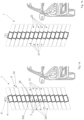
figures 1a and 1b show a brush according to the present invention at two different moments during rotation; -
figure 2 shows a detail of the brush according to the present invention; -
figures 3a and 3b show a brush according to the present invention, alternative to that offigure 1 and at two different moments of the rotation; -
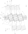
figure 4 shows an exploded view of the brush according to the present invention; -
figures 5 and 6 show a component of a brush according to the present invention and alternative to the previous ones; -
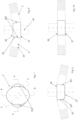
figure 7 shows a view of a detail of a brush which is not within the scope of protection; -
figure 8 shows a sectional view according to the plane A-A offigure 7 ; -
figure 9 shows a sectional view according to the plane B-B offigure 7 ; -
figure 10 shows a sectional view according to the plane C-C offigure 7 ; -
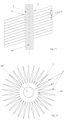
figure 11 shows a schematic sectional view of a further solution of a brush which is not within the scope of the present invention; -
figure 12 shows a schematic view from above of a component illustrated infigure 11 and resting on a horizontal plane; -
figure 13 shows a schematic sectional view which is not within the scope of the present invention; -
figure 14 shows a schematic view from above of a component illustrated infigure 13 and resting on a horizontal plane; -
figure 15 shows a schematic sectional view which is not within the scope of the present invention; -
figure 16 shows a schematic view from above of a component illustrated infigure 15 and resting on a horizontal plane. - In the appended figures, reference number 1 denotes a brush for an automatic vehicle washing system.
- Such brush 1 may comprise
flexible elements 2 intended to come into contact with the vehicle for cleaning and/or drying and/or polishing. Theflexible elements 2 may be made for example of expanded plastic material, EVA or another flexible expanded material with closed cells or not, or fabric, or non-woven fabric, and even a combination of materials. - In the solution illustrated, for example, in
figures 1a, 1b ,2 ,3a, 3b ,4 ,7-10 theflexible elements 2 comprise/coincide withstraps 20. - In the preferred solution the
straps 20 are fringed. In other words, there are longitudinal cuts at least at the most radially external ends of thestraps 20. Such cuts can affect all or part of the longitudinal extension of thestraps 20. - The
flexible elements 2 may comprise/coincide with longitudinal strings. They have a wire-shaped extension. As will be explained more clearly below, this could for example be the case in which the component illustrated infigures 5 and 6 is used. - The brush 1 comprises a central
annular support 3 about which theflexible elements 2 are applied. In the solutions illustrated infigures 1a, 1b ,2 ,3a, 3b ,4 ,7-10 thesupport 3 is preferably rigid. Appropriately, thecentral support 3 is made of plastic material. Thesupport 3 is preferably a cylindrical tube. As already explained above theflexible elements 2 used with therigid support 3 are thestraps 20. - In the solution illustrated by way of example in
figures 5 and 6 thesupport 3 comprises/coincides with aflexible band 39 that is annularly folded.Figure 5 showssuch band 39 in an extended configuration,figure 6 showssuch band 39 in an operating configuration in which it is annularly folded. - The
band 39 preferably comprises a plurality ofhousings 390 distributed about the shaft 4 (for the sake of simplicity, infigures 5 and 6 only some ofsuch housings 390 are illustrated; they are advantageously distributed along the surface of the band 39). In the solution exemplified infigures 5 and 6 such housings 390 could be cavities from each of which a corresponding bunch of said longitudinal strings extends (not shown). - In an alternative solution not illustrated the
flexible band 39 may comprise slots from which corresponding straps extend. Such straps are retained in the slots by corresponding retaining bars. Such bars obstruct at least partially the slot leaving two lateral slits for letting two edges of a same strap exit transversally to the prevalent extension direction (thus a similar solution to the one illustrated is obtained although in a different context infigure 4 and better described below). - The brush 1 comprises a
shaft 4 that is rotatable about anaxis 40 of rotation thereof. Advantageously, theaxis 40 extends between the top and the bottom, in particular it is vertical. Possibly (solution not illustrated) it may be horizontally oriented. - In fact, normally in a washing system there is a combination of at least two brushes that rotate about corresponding axes that extend between the top and the bottom and at least one horizontal brush.
- The
shaft 4 crosses thecentral support 3 and places thecentral support 3 in rotation about theaxis 40 of rotation. Theshaft 4 is therefore constrained to thesupport 3.Shaft 4 andsupport 3 are therefore solidly constrained to each other. On this point, thecentral support 3 and theshaft 4 comprise a connection means 42 by interference/interlocking (in alternative solutions such connection could take place through threaded connection means or of another type of connection means). The connection means 42 advantageously comprises shapes afforded on a surface of theshaft 4 and/or on a surface of thecentral support 3 facing it. Thecentral support 3 comprises alateral surface 35, from which theflexible elements 2 extend (in this document the description with reference to thelateral surface 35 could be repeated with reference to alateral wall 350 of thesupport 3 incorporating such surface 35). In the preferred solution the part of thelateral surface 35 from which theflexible elements 2 extend is at least partially inclined with respect to the axis ofrotation 40 of theshaft 4. Therefore, the directrix of thesurface 35 is not parallel to theaxis 40. On this point, the connection means 42 could comprise wedge-shaped elements (not illustrated) interposed between theshaft 4 and thelateral surface 35 of the support 3 (solution offigures 1a, 1b ,2 ,3a, 3b ,4 ,5, 6 ). Advantageously such wedge-shaped elements could be made in a single body with the support 3 (solution not illustrated) or could be coupled to theshaft 4 or to thesupport 3. Therefore, the wedge shape allows the absence of coaxiality between theshaft 4 and thesupport 3. - The
central support 3 comprises a retaining means 30 for retaining a strip (sheet-like body) which is folded (transversally to a preponderant extension direction). In this way two of said straps 20 are formed, which are reciprocally flanked (see for example the straps indicated byreference numbers figure 4 ). Advantageously all thestraps 20 are obtained in pairs in this way. The retaining means 30 comprise afastening bar 31 which has a preponderant extension direction 310 (in alternative solutions the connection could take place through screw, rivet, plug, Velcro fastenings, seams, etc.). Thefastening bar 31 is removably connected to remaining parts of thecentral support 3. The strip that forms a pair ofbands 20 is folded around thefastening bar 31. Appropriately thefastening bar 31 is inserted in a bayonet fashion in the remaining parts of thesupport 3. In particular thefastening bar 31 is inserted in one of theslots 38 afforded along thelateral surface 35 of thesupport 3.Such slots 38 are preferably oriented along the directrices of thelateral surface 35 of the support 3 (however, in an alternative solution they could be inclined with respect to such directrix). In particular each pair ofstraps 20 is constrained by means of acorresponding fastening bar 31. - The generatrix of the
lateral surface 35 is not necessarily a straight line, but may be a curved line. Furthermore, theinclined surface 35 may have troughs and/or reliefs due, for example, to the presence of theslots 38 closed by the fastening bars 31 (that generate alateral surface 35 that is not flat). - Appropriately one end of the
straps 20, placed at thesupport 3, extends along a line (preferably a straight line) inclined with respect to theaxis 40 of rotation. - The
fastening bar 31 is inclined with respect to adirection 400 identified by theaxis 40 of rotation of theshaft 4. - An imaginary extension of the
fastening bar 31 along thepreponderant extension direction 310 thereof extends towards theshaft 4 or an imaginary extension of theshaft 4. Thefastening bar 31 and/or the corresponding slot may be rectilinear or curved (e.g. defining a helical stretch). - Starting from the central support 3 a
first group 21 of saidflexible elements 2 in an extended and rectilinear configuration extends upwards and asecond group 22 of saidflexible elements 2 in an extended and rectilinear configuration extends downwards. In an alternative solution not illustrated theflexible elements 2 of one from among the first and thesecond group flexible elements 2 hit the vehicle at different heights simulating an oscillatory motion that optimises the wash. This is a result of the fact that thelateral surface 35 is inclined with respect to theaxis 40. Appropriately thecentral support 3 comprises twoopposite bases lateral surface 35 extends. Appropriately anystraps 20 extend for at least 50%, preferably at least 75%, of the distance between the twoopposite bases - Reference is to be made below by way of example to
figures 1a, 1b ,2 ,3a, 3b ,4 ,5, 6 . The first and thesecond group straps 20 lie, at least in part, on diametrically opposite positions. - Appropriately the
central support 3 is not coaxial with the axis ofrotation 40 of theshaft 4. - On this point, the
support 3 identifies alongitudinal axis 300 about which thesupport 3 extends annularly. Thelongitudinal axis 300 is incident and inclined with respect to the axis ofrotation 40 of theshaft 4. Infigures 1a, 1b ,2 ,3a, 3b ,6 such inclination could even be considered "exaggerated", but this has been done to highlight it better. Appropriately the angle between theaxis 300 and theaxis 40 is less than 45°, advantageously less than 25°, preferably less than 15°. At the same time such angle is preferably greater than 5°. - Appropriately at least one of the two
bases axis 40 of rotation of the shaft 4 (see for examplefigures 1a, 1b ,2 ,6 ). This can be repeated advantageously for bothbases - Reference should now be made instead to the schematic and alternative solution illustrated in
figures 7-10 . For the sake of simplicity, infigure 7 theflexible elements 2 have not been illustrated which are instead schematically highlighted in the sections offigures 8-10 . - The
central support 3 comprises alateral surface 35 comprising afirst portion 351 tapered downwards and asecond portion 352 tapered upwards that are in succession along thelateral surface 35 following the rotation direction of thesupport 3. In such case theflexible elements 2 that extend from thefirst portion 351 hit the vehicle lower down than those that extend from thesecond portion 352. This alternation ofstraps 20 that hit the vehicle further down and further up simulates an oscillatory motion of the brush 1. - In this case the
axis 300 of thesupport 3 and theaxis 40 of rotation of therotation shaft 4 extend along the same direction. Thelateral surface 35 instead remains inclined with respect to theaxis 40 of rotation (at least for 75% of its angular extension about theaxis 300; it is to be noted in fact infigure 10 that in such specific section the generatrix is parallel to the axis 40). - As exemplified in
figures 1a, 1b ,2 ,3a, 3b , the brush 1 comprises a plurality ofannular supports 3 that are in succession with each other along saidshaft 4 and crossed by thesame shaft 4. - A brush 1 for a vehicle washing system (see for example
figures 11 - 16 ) which is not within the scope of the present invention comprises: -
flexible elements 2 intended to come into contact with the vehicle for cleaning and/or drying and/or polishing; - a central
annular support 3 from which theflexible elements 2 extend; as exemplified infigures 11 and13 appropriately thecentral support 3 and theflexible elements 2 are a single monolithic body; - a
shaft 4 rotating about itsown axis 40 of rotation; theshaft 4 crosses thecentral support 3 and places thecentral support 3 in rotation about theaxis 40 of rotation. - The
central support 3 defines anupper surface 356 that circumscribes acircle 357 or another figure crossed by the shaft 4 (it is the upper section of the hole that crosses thecentral support 3; such hole is normally crossed by the shaft 4); a straight line passing through the geometric centre of gravity of said circle 357 (or other figure) and orthogonal to said circle 357 (or other figure) is inclined with respect to theaxis 40 of rotation of theshaft 4. Such inclination is fixed during operation. Such inclination is advantageously comprised between 5° and 25°. - For a stretch of the perimeter of said circle 357 (or other geometric figure) the
central support 3 extends upwards from theshaft 4, while for a stretch of the perimeter of said circle 357 (or other geometric figure) thecentral support 3 extends downwards from the shaft 4 (seefigures 11 and13 ). Appropriately, thesupport 3 extends upwards for at least one third (or even half) of the perimeter of said circle 357 (or other figure). Thesupport 3 extends downwards for at least one third (or even half) of the perimeter of saidcircle 357 or other figure. In fact, thesupport 3 is inclined with respect to the horizontal plane and therefore it partially projects upwards and partially projects downwards. - Appropriately the
brush 2 comprises a plurality ofcentral supports 3 stacked along adirection 358 inclined with respect to the axis of rotation of the shaft 4 (as previously indicated, such inclination is advantageously comprised between 5° and 25°;figures 11 and13 and15 exaggerate such inclination for highlighting it better). Thesupports 3 extend in thickness along the stacking direction. As exemplified infigures 11 and13 each of saidsupports 3 is in a single body with a plurality offlexible elements 2 that extend in spoke fashion. The interface between eachsupport 3 and theflexible elements 2 that extend therefrom defines alateral surface 35 of the support 3 (see broken line with two points offigure 12 ). - Reference is now made to the solutions of
figures 15 and 16 . In that case thecentral support 3 also acts as a spacer ring (separating two layers of stacked flexible elements 2). Theflexible elements 2 extend from the support 3 (seefigure 15 ). In particular theflexible elements 2 extend in spoke fashion moving away from thecentral support 3. Suchflexible elements 2 are connected, for example by gluing, to the overlappingcentral support 3. - Reference is now made to the solutions of
figures 11 and 12 . In that case thecentral support 3 and theflexible elements 2 are integrated in a single monolithic body; thecentral support 3 is therefore the internal portion of the monolithic body. In that case a plurality ofcentral supports 3 each associated with correspondingflexible elements 2 that extend in spoke fashion are stacked onto each other. - Reference is made to the solution of
figures 13 and 14 . Such solution differs from the previous one as in that case thecentral supports 3 are glued to each other to form an assembly (in such figures the layer of glue is indicated by reference number 359). - The subject matter of the present invention is also an operating method of a brush 1 of an automatic vehicle washing system. Conveniently, such brush 1 may be of the type having one or more of the characteristics described hereinabove. Appropriately the method comprises the step of placing in rotation a
shaft 4 that rotates about anaxis 40 of rotation. Theshaft 4 crosses and draws in rotation a centralannular support 3 about whichflexible elements 2 are applied and are intended to come into contact with the vehicle for cleaning and/or drying and/or polishing. - The
central support 3 comprises alateral surface 35, from which theflexible elements 2 extend, which is inclined with respect to theaxis 40 of rotation of theshaft 4. Thelateral surface 35 is appropriately annular. - The
central support 3 comprises twoopposite bases lateral surface 35 extends. Theflexible elements 2 could advantageously be straps 20. Advantageously in that case thestraps 20 extend for at least 50%, preferably at least 75%, of the distance between the twoopposite bases - A
first pair 21 ofstraps 2 are adjacent to each other and at least at a predetermined rotation speed of theshaft 4 an orthogonal projection thereof on the axis ofrotation 40 is closer to a firstaxial end 41 of said brush 1 with respect to at least a second pair of said straps 2 (also the straps of said second pair are adjacent to each other). This happens for the entire rotation (at 360°) about theaxis 40 of theshaft 4. For example, in the case offigure 2 point H representing theupper straps 20 is closer to thefirst end 41 of theshaft 4 with respect to the point K representing the lower straps 20. -
Adjacent straps 20 means twostraps central support 3 and are in adjacent succession with respect to a rotation about theaxis 40 of thesupport 3. - Furthermore, still with reference to
figure 2 , as thestrap 20 is inclined, the distance between points Y and H is shorter than the distance between points Y and Z. In other words if thestrap 20 is taut and straight, a point that lies at an end of thestrap 20 has a distance from theaxis 40 that is shorter if evaluated in the radial sense rather than along a longitudinal extension direction of thestrap 20. - Appropriately (see solution of
figure 1a, 1b ,2 ,3a, 3b ,6 ) theaxis 40 of rotation of theshaft 4 and alongitudinal axis 300 of thecentral support 3 extend along two different directions. - In an alternative solution (see
figures 7-10 ), thelateral surface 35 of thesupport 3 comprises afirst portion 351 tapered downwards and asecond portion 352 tapered upwards that are in succession along thelateral surface 35 following the rotation direction of thesupport 3. - When the
shaft 4 is placed in rotation, thestraps 20 that extend from thefirst portion 351 contact the vehicle lower down than thestraps 20 that extend from thesecond portion 352. In that case, the axis ofrotation 40 of theshaft 4 and thelongitudinal axis 300 of thecentral support 3 advantageously extend along the same direction, in particular they coincide. - The present invention achieves important advantages.
- Above all, the
flexible elements 2 that extend from an inclined surface with respect to theaxis 40 of rotation allow the brush 1 to acquire the rotatory motion, but also to simulate the wave motion. Furthermore, the inclination solves the problems connected with the axial distance existing between theflexible elements 2 placed at a junction zone of twoconsecutive supports 3. This allows the cleaning power and the friction surface to be increased as well as allowing more uniform cleaning. Theinclined elements 2 also gradually impact the surfaces having a more delicate effect on the paints and a reduction in noise.
Claims (10)
- A brush for a vehicle washing system comprising:- flexible elements (2) intended to come into contact with the vehicle for cleaning and/or drying and/or polishing;- a central annular support (3) from which the flexible elements (2) extend;- a shaft (4) rotating about its own axis (40) of rotation, said shaft (4) crossing said central annular support (3) and placing said central annular support (3) in rotation about said axis (40) of rotation;the central annular support (3) comprising a lateral surface (35), from which said flexible elements (2) extend, which is inclined with respect to the axis (40) of rotation of the shaft (4); the central annular support (3) comprising two opposite bases (36, 37) between which the lateral surface (35) extends;the central annular support (3) comprising a lateral wall (350) incorporating the lateral surface (35); the flexible elements (2) are connected to the lateral wall along a generatrix of the lateral wall (350) and extend perpendicular to said lateral wall during rotation;said support (3) identifies a longitudinal axis (300) about which the central annular support (3) extends annularly, said longitudinal axis (300) being incident and inclined with respect to the axis (40) of rotation of the shaft (4).
- The brush according to claim 1, characterised in that starting from the central annular support (3) a first group (21) of said flexible elements (2) in an extended and rectilinear configuration extends upwards and a second group (22) of said flexible elements (2) in an extended and rectilinear configuration extends downwards; the first and the second group (21, 22) of said flexible elements (2) lie in diametrically opposite positions.
- The brush according to claim 1 or 2, characterised in that the central annular support (3) is a cylindrical tube.
- The brush according to any one of the preceding claims, characterised in that the central annular support (3) is rigid.
- The brush according to claim 1 or 2, characterised in that said central annular (3) comprises a flexible band (39) that is annularly bent.
- The brush according to claim 5, characterised in that said flexible elements (2) comprise longitudinal strings; said band (39) comprises a plurality of housings (390) distributed about the shaft (4); from a plurality of said housings (390) a corresponding bunch of said longitudinal strings extends.
- The brush according to claim 1 or 2, characterised in that the flexible elements (2) comprise longitudinal straps (20).
- The brush according to claim 7, characterised in that the central annular support (3) comprises retaining means (30) for retaining a strip folded about its own transversal axis to form two of said straps (20) which are reciprocally flanked; said retaining means (30) comprises a fastening bar (31) which has a preponderant extension direction (310):i) which is inclined with respect to a direction (400) identified by the axis (40) of rotation of the shaft (4);ii) such that an imaginary extension of said fastening bar (31) along said preponderant extension direction (310) extends towards the shaft (4) or towards an imaginary extension of the shaft (4) along the axis of rotation (40).
- The brush according to claim 7 or 8, characterised in that an end of the straps (20), placed at the central annular support (3), extends along a line that is inclined with respect to the axis (40) of rotation.
- The brush according to any one of the preceding claims, characterised in that it comprises a plurality of central annular supports (3) that are in succession with each other along said shaft (4) and crossed by the same shaft (4).
Priority Applications (1)
| Application Number | Priority Date | Filing Date | Title |
|---|---|---|---|
| SM20240508T SMT202400508T1 (en) | 2017-11-10 | 2018-09-27 | WASHING SYSTEM BRUSH |
Applications Claiming Priority (2)
| Application Number | Priority Date | Filing Date | Title |
|---|---|---|---|
| IT201700128683 | 2017-11-10 | ||
| PCT/IB2018/057485 WO2019092515A1 (en) | 2017-11-10 | 2018-09-27 | Brush for washing plant |
Publications (3)
| Publication Number | Publication Date |
|---|---|
| EP3500130A1 EP3500130A1 (en) | 2019-06-26 |
| EP3500130B1 true EP3500130B1 (en) | 2024-12-04 |
| EP3500130C0 EP3500130C0 (en) | 2024-12-04 |
Family
ID=61527219
Family Applications (1)
| Application Number | Title | Priority Date | Filing Date |
|---|---|---|---|
| EP18789482.9A Active EP3500130B1 (en) | 2017-11-10 | 2018-09-27 | Brush for car washing plant |
Country Status (11)
| Country | Link |
|---|---|
| US (1) | US11064799B2 (en) |
| EP (1) | EP3500130B1 (en) |
| JP (1) | JP7220162B2 (en) |
| KR (1) | KR20200086221A (en) |
| CN (1) | CN110831460B (en) |
| CA (1) | CA3079685A1 (en) |
| ES (1) | ES2999135T3 (en) |
| HU (1) | HUE070916T2 (en) |
| PL (1) | PL3500130T3 (en) |
| SM (1) | SMT202400508T1 (en) |
| WO (1) | WO2019092515A1 (en) |
Families Citing this family (2)
| Publication number | Priority date | Publication date | Assignee | Title |
|---|---|---|---|---|
| DE202019105411U1 (en) | 2019-09-30 | 2019-10-11 | René Stegemann | Carrier element for fastening band elements of a rotary washing brush and rotary washing brush with such support elements |
| EP4342333A1 (en) | 2022-09-23 | 2024-03-27 | Favagrossa Edoardo S.r.l. | Brush for drying and/or washing vehicles |
Citations (1)
| Publication number | Priority date | Publication date | Assignee | Title |
|---|---|---|---|---|
| JP2013079030A (en) * | 2011-10-05 | 2013-05-02 | Yonezu Brush Kk | Car washing brush |
Family Cites Families (11)
| Publication number | Priority date | Publication date | Assignee | Title |
|---|---|---|---|---|
| GB871817A (en) * | 1959-02-12 | 1961-07-05 | Smith Bros & Webb | Brushing means for washing vehicles |
| JPS484267U (en) * | 1971-06-14 | 1973-01-18 | ||
| JPS4819379U (en) * | 1971-07-13 | 1973-03-05 | ||
| US5134742A (en) * | 1990-02-08 | 1992-08-04 | N/S Corporation | Vehicle washing apparatus |
| JPH08282451A (en) * | 1995-04-14 | 1996-10-29 | Takeuchi Iron Works Corp | Vehicle body surface washing device |
| IT1313977B1 (en) | 1999-10-28 | 2002-09-26 | Favagrossa Edoardo Srl | BRUSHES PERFECTED PARTICULARLY DESIGNED FOR AUTOMATIC WASHING SYSTEMS AND / OR FOR POLISHING OF VEHICLES IN GENERAL. |
| ITMI20052467A1 (en) | 2005-12-22 | 2007-06-23 | Favagrossa Edoardo Srl | ROTATING BRUSH FOR WASHING SYSTEMS PARTICULARLY FOR VEHICLES |
| ITMI20061742A1 (en) | 2006-09-12 | 2008-03-13 | Favagrossa Edoardo Srl | VELVETIC STRIPED CLEANING ELEMENT, PARTICULARLY FOR THE CONSTRUCTION OF ROTATING BRUSHES FOR VEHICLE WASHING SYSTEMS |
| KR100919923B1 (en) * | 2009-04-02 | 2009-10-07 | 한림기계 주식회사 | Car Wash Brush for Automatic Car Wash |
| US9714011B2 (en) * | 2011-11-02 | 2017-07-25 | Washme Properties, Llc | Vehicle wash component |
| ITUB20161197A1 (en) * | 2016-03-01 | 2017-09-01 | Favagrossa Edoardo Srl | ROTATING BRUSH FOR WASHING SYSTEMS, PARTICULARLY FOR VEHICLES |
-
2018
- 2018-09-27 JP JP2019565813A patent/JP7220162B2/en active Active
- 2018-09-27 SM SM20240508T patent/SMT202400508T1/en unknown
- 2018-09-27 ES ES18789482T patent/ES2999135T3/en active Active
- 2018-09-27 HU HUE18789482A patent/HUE070916T2/en unknown
- 2018-09-27 CA CA3079685A patent/CA3079685A1/en active Pending
- 2018-09-27 US US16/333,540 patent/US11064799B2/en active Active
- 2018-09-27 KR KR1020197028582A patent/KR20200086221A/en not_active Ceased
- 2018-09-27 CN CN201880042619.5A patent/CN110831460B/en active Active
- 2018-09-27 WO PCT/IB2018/057485 patent/WO2019092515A1/en not_active Ceased
- 2018-09-27 EP EP18789482.9A patent/EP3500130B1/en active Active
- 2018-09-27 PL PL18789482.9T patent/PL3500130T3/en unknown
Patent Citations (1)
| Publication number | Priority date | Publication date | Assignee | Title |
|---|---|---|---|---|
| JP2013079030A (en) * | 2011-10-05 | 2013-05-02 | Yonezu Brush Kk | Car washing brush |
Also Published As
| Publication number | Publication date |
|---|---|
| HUE070916T2 (en) | 2025-07-28 |
| US20200100584A1 (en) | 2020-04-02 |
| SMT202400508T1 (en) | 2025-01-14 |
| JP7220162B2 (en) | 2023-02-09 |
| ES2999135T3 (en) | 2025-02-24 |
| JP2021502287A (en) | 2021-01-28 |
| CA3079685A1 (en) | 2019-05-16 |
| PL3500130T3 (en) | 2025-03-24 |
| US11064799B2 (en) | 2021-07-20 |
| WO2019092515A1 (en) | 2019-05-16 |
| EP3500130C0 (en) | 2024-12-04 |
| CN110831460B (en) | 2021-09-28 |
| CN110831460A (en) | 2020-02-21 |
| KR20200086221A (en) | 2020-07-16 |
| EP3500130A1 (en) | 2019-06-26 |
Similar Documents
| Publication | Publication Date | Title |
|---|---|---|
| EP3500130B1 (en) | Brush for car washing plant | |
| US10882497B2 (en) | Brush construction for motor vehicle washing systems | |
| CN105555167A (en) | Rotary brush, for motor vehicle washing systems | |
| US20090020138A1 (en) | Pleated car wash element, method of manufacture and method of attachment | |
| JP2013531197A5 (en) | ||
| JP2016016364A (en) | Solar panel cleaning system | |
| US10549728B1 (en) | Reverse rotation side washer for vehicles including a shaft assembly and retrofit discs | |
| CN103928742B (en) | The elastic force constraint of the inflating expanded parabolic antenna of a kind of fin-plate type launches controlling organization | |
| KR20190063499A (en) | Wind collection apparatus for wind turbine generator | |
| KR101489878B1 (en) | Apparatus for expelling wild birds | |
| US20160333864A1 (en) | Power amplification and production device | |
| US1850265A (en) | Moving picture reel construction | |
| US20050268412A1 (en) | Shaped washing elements for vehicle wash systems | |
| CN203985117U (en) | Corn-peeling machine | |
| KR20200106489A (en) | Wind power station | |
| CN103904407A (en) | Motor-drive unfolding control mechanism of ribbed plate type inflatable unfolding parabolic antenna | |
| US2771241A (en) | Blower wheel | |
| US2032651A (en) | Wind motor | |
| KR20030034658A (en) | Rotetion lmcreasing tecity of waten wheel | |
| RU2569469C2 (en) | Rotor wind-powered engine | |
| KR102551820B1 (en) | Bellows structured support shaft and the parasol using the same | |
| KR200481468Y1 (en) | Wind power generator | |
| US1399318A (en) | Gravity-carrier | |
| US1470118A (en) | Resilient wheel | |
| US2154106A (en) | Vegetable washing machine |
Legal Events
| Date | Code | Title | Description |
|---|---|---|---|
| STAA | Information on the status of an ep patent application or granted ep patent |
Free format text: STATUS: UNKNOWN |
|
| STAA | Information on the status of an ep patent application or granted ep patent |
Free format text: STATUS: THE INTERNATIONAL PUBLICATION HAS BEEN MADE |
|
| PUAI | Public reference made under article 153(3) epc to a published international application that has entered the european phase |
Free format text: ORIGINAL CODE: 0009012 |
|
| STAA | Information on the status of an ep patent application or granted ep patent |
Free format text: STATUS: REQUEST FOR EXAMINATION WAS MADE |
|
| 17P | Request for examination filed |
Effective date: 20190221 |
|
| AK | Designated contracting states |
Kind code of ref document: A1 Designated state(s): AL AT BE BG CH CY CZ DE DK EE ES FI FR GB GR HR HU IE IS IT LI LT LU LV MC MK MT NL NO PL PT RO RS SE SI SK SM TR |
|
| AX | Request for extension of the european patent |
Extension state: BA ME |
|
| DAV | Request for validation of the european patent (deleted) | ||
| DAX | Request for extension of the european patent (deleted) | ||
| STAA | Information on the status of an ep patent application or granted ep patent |
Free format text: STATUS: EXAMINATION IS IN PROGRESS |
|
| 17Q | First examination report despatched |
Effective date: 20221005 |
|
| P01 | Opt-out of the competence of the unified patent court (upc) registered |
Effective date: 20230523 |
|
| GRAP | Despatch of communication of intention to grant a patent |
Free format text: ORIGINAL CODE: EPIDOSNIGR1 |
|
| STAA | Information on the status of an ep patent application or granted ep patent |
Free format text: STATUS: GRANT OF PATENT IS INTENDED |
|
| INTG | Intention to grant announced |
Effective date: 20240712 |
|
| GRAS | Grant fee paid |
Free format text: ORIGINAL CODE: EPIDOSNIGR3 |
|
| GRAA | (expected) grant |
Free format text: ORIGINAL CODE: 0009210 |
|
| STAA | Information on the status of an ep patent application or granted ep patent |
Free format text: STATUS: THE PATENT HAS BEEN GRANTED |
|
| AK | Designated contracting states |
Kind code of ref document: B1 Designated state(s): AL AT BE BG CH CY CZ DE DK EE ES FI FR GB GR HR HU IE IS IT LI LT LU LV MC MK MT NL NO PL PT RO RS SE SI SK SM TR |
|
| REG | Reference to a national code |
Ref country code: GB Ref legal event code: FG4D |
|
| REG | Reference to a national code |
Ref country code: CH Ref legal event code: EP |
|
| REG | Reference to a national code |
Ref country code: DE Ref legal event code: R096 Ref document number: 602018077267 Country of ref document: DE |
|
| REG | Reference to a national code |
Ref country code: IE Ref legal event code: FG4D |
|
| U01 | Request for unitary effect filed |
Effective date: 20241206 |
|
| U07 | Unitary effect registered |
Designated state(s): AT BE BG DE DK EE FI FR IT LT LU LV MT NL PT RO SE SI Effective date: 20241216 |
|
| P04 | Withdrawal of opt-out of the competence of the unified patent court (upc) registered |
Free format text: CASE NUMBER: APP_65529/2024 Effective date: 20241212 |
|
| REG | Reference to a national code |
Ref country code: ES Ref legal event code: FG2A Ref document number: 2999135 Country of ref document: ES Kind code of ref document: T3 Effective date: 20250224 |
|
| PG25 | Lapsed in a contracting state [announced via postgrant information from national office to epo] |
Ref country code: HR Free format text: LAPSE BECAUSE OF FAILURE TO SUBMIT A TRANSLATION OF THE DESCRIPTION OR TO PAY THE FEE WITHIN THE PRESCRIBED TIME-LIMIT Effective date: 20241204 |
|
| PG25 | Lapsed in a contracting state [announced via postgrant information from national office to epo] |
Ref country code: NO Free format text: LAPSE BECAUSE OF FAILURE TO SUBMIT A TRANSLATION OF THE DESCRIPTION OR TO PAY THE FEE WITHIN THE PRESCRIBED TIME-LIMIT Effective date: 20250304 |
|
| PG25 | Lapsed in a contracting state [announced via postgrant information from national office to epo] |
Ref country code: GR Free format text: LAPSE BECAUSE OF FAILURE TO SUBMIT A TRANSLATION OF THE DESCRIPTION OR TO PAY THE FEE WITHIN THE PRESCRIBED TIME-LIMIT Effective date: 20250305 |
|
| PG25 | Lapsed in a contracting state [announced via postgrant information from national office to epo] |
Ref country code: RS Free format text: LAPSE BECAUSE OF FAILURE TO SUBMIT A TRANSLATION OF THE DESCRIPTION OR TO PAY THE FEE WITHIN THE PRESCRIBED TIME-LIMIT Effective date: 20250304 |
|
| PG25 | Lapsed in a contracting state [announced via postgrant information from national office to epo] |
Ref country code: IS Free format text: LAPSE BECAUSE OF FAILURE TO SUBMIT A TRANSLATION OF THE DESCRIPTION OR TO PAY THE FEE WITHIN THE PRESCRIBED TIME-LIMIT Effective date: 20250404 |
|
| PG25 | Lapsed in a contracting state [announced via postgrant information from national office to epo] |
Ref country code: SK Free format text: LAPSE BECAUSE OF FAILURE TO SUBMIT A TRANSLATION OF THE DESCRIPTION OR TO PAY THE FEE WITHIN THE PRESCRIBED TIME-LIMIT Effective date: 20241204 |
|
| REG | Reference to a national code |
Ref country code: HU Ref legal event code: AG4A Ref document number: E070916 Country of ref document: HU |
|
| REG | Reference to a national code |
Ref country code: CH Ref legal event code: U11 Free format text: ST27 STATUS EVENT CODE: U-0-0-U10-U11 (AS PROVIDED BY THE NATIONAL OFFICE) Effective date: 20251001 |
|
| PGFP | Annual fee paid to national office [announced via postgrant information from national office to epo] |
Ref country code: SM Payment date: 20250905 Year of fee payment: 8 |
|
| PLBE | No opposition filed within time limit |
Free format text: ORIGINAL CODE: 0009261 |
|
| STAA | Information on the status of an ep patent application or granted ep patent |
Free format text: STATUS: NO OPPOSITION FILED WITHIN TIME LIMIT |
|
| PGFP | Annual fee paid to national office [announced via postgrant information from national office to epo] |
Ref country code: TR Payment date: 20250910 Year of fee payment: 8 Ref country code: PL Payment date: 20250911 Year of fee payment: 8 |
|
| REG | Reference to a national code |
Ref country code: CH Ref legal event code: L10 Free format text: ST27 STATUS EVENT CODE: U-0-0-L10-L00 (AS PROVIDED BY THE NATIONAL OFFICE) Effective date: 20251015 |
|
| PGFP | Annual fee paid to national office [announced via postgrant information from national office to epo] |
Ref country code: HU Payment date: 20250922 Year of fee payment: 8 Ref country code: GB Payment date: 20250923 Year of fee payment: 8 |
|
| PGFP | Annual fee paid to national office [announced via postgrant information from national office to epo] |
Ref country code: CZ Payment date: 20250916 Year of fee payment: 8 |
|
| U20 | Renewal fee for the european patent with unitary effect paid |
Year of fee payment: 8 Effective date: 20250923 |
|
| 26N | No opposition filed |
Effective date: 20250905 |
|
| PGFP | Annual fee paid to national office [announced via postgrant information from national office to epo] |
Ref country code: CH Payment date: 20251001 Year of fee payment: 8 |
|
| PGFP | Annual fee paid to national office [announced via postgrant information from national office to epo] |
Ref country code: ES Payment date: 20251015 Year of fee payment: 8 |