EP3500040B1 - Method and apparatus for random access in wireless communication system - Google Patents
Method and apparatus for random access in wireless communication system Download PDFInfo
- Publication number
- EP3500040B1 EP3500040B1 EP17838342.8A EP17838342A EP3500040B1 EP 3500040 B1 EP3500040 B1 EP 3500040B1 EP 17838342 A EP17838342 A EP 17838342A EP 3500040 B1 EP3500040 B1 EP 3500040B1
- Authority
- EP
- European Patent Office
- Prior art keywords
- prach
- carrier
- random access
- index
- anchor
- Prior art date
- Legal status (The legal status is an assumption and is not a legal conclusion. Google has not performed a legal analysis and makes no representation as to the accuracy of the status listed.)
- Active
Links
- 238000000034 method Methods 0.000 title claims description 70
- 238000004891 communication Methods 0.000 title claims description 23
- 239000000969 carrier Substances 0.000 claims description 145
- 230000000977 initiatory effect Effects 0.000 claims description 12
- 230000004044 response Effects 0.000 claims description 10
- 108010008885 Cellulose 1,4-beta-Cellobiosidase Proteins 0.000 description 57
- 241000701796 Fowl aviadenovirus 1 Species 0.000 description 50
- 101150084500 cel2 gene Proteins 0.000 description 22
- 230000005540 biological transmission Effects 0.000 description 18
- 230000015654 memory Effects 0.000 description 11
- 101100517651 Caenorhabditis elegans num-1 gene Proteins 0.000 description 6
- 238000010586 diagram Methods 0.000 description 3
- 230000000694 effects Effects 0.000 description 3
- 101150026317 cel3 gene Proteins 0.000 description 2
- 230000006870 function Effects 0.000 description 2
- 238000013507 mapping Methods 0.000 description 2
- 230000001419 dependent effect Effects 0.000 description 1
- 238000010295 mobile communication Methods 0.000 description 1
Images


Classifications
-
- H—ELECTRICITY
- H04—ELECTRIC COMMUNICATION TECHNIQUE
- H04W—WIRELESS COMMUNICATION NETWORKS
- H04W74/00—Wireless channel access, e.g. scheduled or random access
- H04W74/08—Non-scheduled or contention based access, e.g. random access, ALOHA, CSMA [Carrier Sense Multiple Access]
- H04W74/0866—Non-scheduled or contention based access, e.g. random access, ALOHA, CSMA [Carrier Sense Multiple Access] using a dedicated channel for access
- H04W74/0883—Non-scheduled or contention based access, e.g. random access, ALOHA, CSMA [Carrier Sense Multiple Access] using a dedicated channel for access for un-synchronized access
-
- H—ELECTRICITY
- H04—ELECTRIC COMMUNICATION TECHNIQUE
- H04W—WIRELESS COMMUNICATION NETWORKS
- H04W74/00—Wireless channel access, e.g. scheduled or random access
- H04W74/08—Non-scheduled or contention based access, e.g. random access, ALOHA, CSMA [Carrier Sense Multiple Access]
- H04W74/0833—Non-scheduled or contention based access, e.g. random access, ALOHA, CSMA [Carrier Sense Multiple Access] using a random access procedure
-
- H—ELECTRICITY
- H04—ELECTRIC COMMUNICATION TECHNIQUE
- H04W—WIRELESS COMMUNICATION NETWORKS
- H04W48/00—Access restriction; Network selection; Access point selection
- H04W48/16—Discovering, processing access restriction or access information
-
- H—ELECTRICITY
- H04—ELECTRIC COMMUNICATION TECHNIQUE
- H04W—WIRELESS COMMUNICATION NETWORKS
- H04W72/00—Local resource management
- H04W72/04—Wireless resource allocation
- H04W72/044—Wireless resource allocation based on the type of the allocated resource
-
- H—ELECTRICITY
- H04—ELECTRIC COMMUNICATION TECHNIQUE
- H04W—WIRELESS COMMUNICATION NETWORKS
- H04W72/00—Local resource management
- H04W72/20—Control channels or signalling for resource management
- H04W72/23—Control channels or signalling for resource management in the downlink direction of a wireless link, i.e. towards a terminal
-
- H—ELECTRICITY
- H04—ELECTRIC COMMUNICATION TECHNIQUE
- H04W—WIRELESS COMMUNICATION NETWORKS
- H04W74/00—Wireless channel access, e.g. scheduled or random access
- H04W74/002—Transmission of channel access control information
-
- H—ELECTRICITY
- H04—ELECTRIC COMMUNICATION TECHNIQUE
- H04W—WIRELESS COMMUNICATION NETWORKS
- H04W74/00—Wireless channel access, e.g. scheduled or random access
- H04W74/002—Transmission of channel access control information
- H04W74/006—Transmission of channel access control information in the downlink, i.e. towards the terminal
-
- H—ELECTRICITY
- H04—ELECTRIC COMMUNICATION TECHNIQUE
- H04W—WIRELESS COMMUNICATION NETWORKS
- H04W74/00—Wireless channel access, e.g. scheduled or random access
- H04W74/08—Non-scheduled or contention based access, e.g. random access, ALOHA, CSMA [Carrier Sense Multiple Access]
-
- H—ELECTRICITY
- H04—ELECTRIC COMMUNICATION TECHNIQUE
- H04W—WIRELESS COMMUNICATION NETWORKS
- H04W76/00—Connection management
- H04W76/10—Connection setup
- H04W76/18—Management of setup rejection or failure
Description
- The present disclosure relates to a method and an apparatus for wireless communication.
-
WO 2015/117283 A1 relates to a method for configuring a physical random access channel (PRACH) resource comprises: a base station configuring a supported coverage enhancement level and a PRACH resource corresponding to the coverage enhancement level; and the base station sending, to a user equipment, a resource index and/or resource configuration information of the PRACH resource configured for the coverage enhancement level, so that the user equipment obtains the corresponding PRACH resource and sends a preamble on the obtained PRACH resource. - In wireless communication systems such as enhanced Machine Type Communication (eMTC) and Narrow Band Internet of Things (NB-loT) standard protocols, a base station (e.g., an evolved NodeB (eNodeB)) can initiate a random access process e.g., by transmitting a Physical Downlink Control Channel (PDCCH) order instructing a User Equipment (UE) to initiate a random access process. In this case, the base station can indicate information on Physical Random Access Channel (PRACH) resources to be used by the UE (the PRACH information indicated by the PDCCH order is shown in Table 1). Upon receiving the instruction from the base station, the UE transmits PRACH over the resources indicated by the base station. In the eMTC system, the UE transmits PRACH using a preamble codeword indicated by the base station.
Table 1 eMTC NB-loT Description Starting CE Level Starting number of NPRACH repetitions Coverage level at which UE transmits PRACH initially, i.e., UE initiates random access over a PRACH resource set corresponding to the coverage level initially PRACH Mask Index Subcarrier indication of NPRACH Time-frequency resource index for UE to transmit PRACH (eMTC) Frequency-domain sub-carrier ID for UE to transmit PRACH (NB-loT) Preamble Index Preamble codeword to be used by UE for PRACH - In the eMTC and NB-loT systems, PRACH resources are configured depending on coverage levels. Each coverage level corresponds to a set of PRACH time-frequency resources, a number of PRACH repetitions and a number of random accesses. In the eMTC system, a set of preamble codewords is also configured for each coverage level.
- For a base station initiated random access process, the PRACH resource index, sub-carrier ID or preamble codeword indicated by the base station is necessarily included in the set of PRACH resources for the initial coverage level, so as to ensure that the UE can initiate a random access process over the PRACH resources indicated by the base station at the initial coverage level. However, when the coverage level needs to be increased after the UE has failed in a number of random accesses over the PRACH resources indicated by the base station, the PRACH resource index, sub-carrier ID or preamble codeword indicated by the base station may not be included in the set of PRACH resources for the higher level. In this case, the UE would not be able to initiate a random access or the UE transmits PRACH according to the PRACH information indicated by the base station but the base station would not respond. In either case, the random access will fail, resulting in a reduced success rate of the base station-initiated random accesses.
- There is currently no effective solution to the technical problem in the related art associated with low success rate of random accesses initiated by radio base stations.
- The invention is specified by the independent claims. Preferred embodiments are defined in the dependent claims. The present disclosure provides a method and an apparatus for wireless communication, capable of at least solving the technical problem in the related art associated with low success rate of random accesses initiated by radio base stations.
- In the present disclosure, indication information transmitted from a radio base station is received. The indication information instructs a user terminal to initiate a random access. A target Physical Random Access Channel (PRACH) resource is determined from available resources based on a current coverage level and resource information carried in the indication information. The target PRACH resource is used for transmitting a PRACH signal for initiating the random access. In response to a failure to initiate the random access over the target PRACH resource, the target PRACH resource is re-determined from the available resources based on an updated coverage level and the resource information, and the PRACH signal is transmitted over the re-determined target PRACH resource. In this way, it is possible to solve the technical problem in the related art associated with low success rate of random accesses initiated by radio base stations, thereby achieving a technical effect of an increased success rate of random accesses.
- The present disclosure can be further understood with reference to the figures described below, which constitute a part of the present disclosure. The illustrative embodiments of the present disclosure and descriptions thereof are provided for explaining, rather than limiting, the present disclosure. In the figures:
-
Fig. 1 is a schematic diagram showing an optional user terminal according to the present disclosure; -
Fig. 2 is a flowchart illustrating a process of random access in a wireless communication system according to the present disclosure; -
Fig. 3 is a flowchart illustrating an alternative process of random access in a wireless communication system according to the present disclosure -
Fig. 4 is a flowchart illustrating an alternative process of random access in a wireless communication system according to the present disclosure; and -
Fig. 5 is a schematic diagram showing an apparatus for random access in a wireless communication system according to the present disclosure. - In the following, each of the described methods, apparatuses, examples, and aspects which does not fully correspond to the invention as defined in the claims is thus not according to the invention and is, as well as the whole description, present for illustration purposes only or to highlight specific aspects or features of the claims.
- It is to be noted that, the terms such as "first", "second" and so on in the description, claims and figures are used for distinguishing among similar objects and do not necessarily imply any particularly order or sequence.
- The method provided according to Embodiment 1 of the present disclosure can be performed in a user terminal, a computer terminal or a similar computing device. When the method is performed in a user terminal for example, as shown in
Fig. 1 , the user terminal can include: one or more processors 101 (only one is shown, which includes, but not limited to, a processing device like a microprocessor such as MCU or a programmable logic device such as FPGA), amemory 103 for storing data, and atransmission device 105 for providing communication functions. It can be appreciated by those skilled in the art that the structure shown inFig. 1 is illustrative only, and the structure of the above electronic device is not limited thereto. - The
memory 103 can store software programs and modules of software applications, e.g., program instructions/modules associated with the method for device control according to the present disclosure. Theprocessor 101 performs various functional applications and data processing operations, i.e., performing the above method, by executing the software programs and modules stored in thememory 103. The memory may include a random cache or non-volatile memory such as one or more magnetic storage devices, flash memories or other non-volatile solid-state memories. In some examples, the memory may further include one or more memories which are remote from the processor and can be connected to the computer terminal via a network. Examples of such network include, but not limited to, Internet, an intranet of an enterprise, a Local Area Network (LAN), a mobile communication network, and any combination thereof. - It is to be noted that the memory can store codes for steps of: receiving indication information transmitted from a radio base station, the indication information instructing a user terminal to initiate a random access; determining a target Physical Random Access Channel (PRACH) resource from available resources based on a current coverage level and resource information carried in the indication information, the target PRACH resource being used for transmitting a PRACH signal for initiating the random access and the current coverage level being a coverage level at which the random access is to be initiated currently; and re-determining, in response to a failure to initiate the random access over the target PRACH resource, the target PRACH resource from the available resources based on an updated coverage level and the resource information, and transmitting the PRACH signal over the re-determined target PRACH resource.
- The transmission device can transmit or receive data via a network. The network can be e.g., a wireless network provided by a communication provider of the computer terminal. In an example, the transmission device includes a network adaptor, or Network Interface Controller (NIC), which can be connected to other network devices via a base station for communication with Internet. In an example, the transmission device can be a Radio Frequency (RF) module for communicating with Internet wirelessly.
- According to an embodiment of the present disclosure, a method for random access in a wireless communication system is provided. It is to be noted that, the steps shown in the flowchart can be performed in a computer system executing a set of computer executable instructions. While a logical sequence order is shown in the flowchart, in some cases the steps as shown or described can be performed in a different order than the one as shown herein.
-
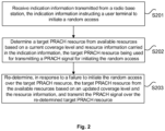
Fig. 2 is a flowchart illustrating a process of random access in a wireless communication system according to the present disclosure. As shown inFig. 2 , the process flow includes the following steps. - At step S201, indication information transmitted from a radio base station is received. The indication information instructs a user terminal to initiate a random access.
- At step S202, a target PRACH resource is determined from available resources based on a current coverage level and resource information carried in the indication information. The target PRACH resource is used for transmitting a PRACH signal for initiating the random access. The current coverage level is a coverage level at which the random access is to be initiated currently. The available resources are resources allowable to be used at the current coverage level.
- At step S203, in response to a failure to initiate the random access over the target PRACH resource, the target PRACH resource is re-determined from the available resources based on an updated coverage level and the resource information, and the PRACH signal is transmitted over the re-determined target PRACH resource.
- With the above embodiments, indication information transmitted from a radio base station is received. The indication information instructs a user terminal to initiate a random access. A target PRACH resource is determined from available resources based on a current coverage level and resource information carried in the indication information. The target PRACH resource is used for transmitting a PRACH signal for initiating the random access. In response to a failure to initiate the random access over the target PRACH resource, the target PRACH resource is re-determined from the available resources based on an updated coverage level and the resource information, and the PRACH signal is transmitted over the re-determined target PRACH resource. In this way, it is possible to solve the technical problem in the related art associated with low success rate of random accesses initiated by radio base stations, thereby achieving a technical effect of an increased success rate of random accesses.
- Optionally, the above steps may be performed by a user terminal, as a non-limiting example.
- At the step S201, when the indication information transmitted from the radio base station is received, the indication information may include PDCCH order information. That is, a base station, or base station, may transmit the indication information via a PDCCH order. However, the present disclosure it not limited to this, and other types of base stations may use similar messages for transmission.
- At the step S202, when the target PRACH resource is determined from available resources based on the current coverage level and the resource information carried in the indication information, the resource information may be mapped to the target PRACH resource from resources available at the current coverage level. The target PRACH resource may be determined based on a scheme corresponding to a system type of the radio base station.
- When the wireless communication system is an eMTC system, the target PRACH resource can include a target time-frequency resource and a target codeword for transmitting the PRACH signal. The operation of determining a target PRACH resource from available resources based on a current coverage level and resource information carried in the indication information can include: determining the target time-frequency resource based on a number of time-frequency resources available at the current coverage level and a time-frequency resource index in the resource information; and/or determining the target codeword based on a start codeword and an end codeword of preambles at the current coverage level and a preamble index in the resource information.
- Optionally, the operation of determining the target time-frequency resource based on the number of time-frequency resources available at the current coverage level and the time-frequency resource index in the resource information can include: calculating a first index, ID2, based on the number, Num1, of the available time-frequency resources and the time-frequency resource index, ID1, in the resource information according to a predetermined equation of ID2=(ID1-K1)mod(Num1)+K2 or ID2=(ID1)mod(Num1)+K3, where K1, K2 and K3 are constants; and determining a time-frequency resource corresponding to ID2 as the target time-frequency resource.
- The above "mod" represents a modulo operation.
- The operation of determining the target codeword based on the start codeword and the end codeword of the preambles at the current coverage level and the preamble index in the resource information can include: calculating a second index, ID6, based on an index, ID3, of the start codeword, an index, ID4, of the end codeword and the preamble index, ID5, as ID6=ID3+(ID5)mod(ID4-ID3+1), or calculating the second index ID6 based on the index ID3 of the start codeword, the index ID4 of the end codeword and a start codeword index, ID9, corresponding to a coverage level indicated in the indication information, as ID6=ID3+(ID5-ID9)mod(ID4-ID3+1); and determining a codeword corresponding to ID6 as the target codeword.
- When the wireless communication system is a NB-IoT system, the target PRACH resource can include a target sub-carrier for transmitting the PRACH signal, and the operation of mapping the resource information to the target PRACH resource from resources available at the current coverage level can include: determining the target sub-carrier based on a number of sub-carriers and an index of a start sub-carrier at the current coverage level and a sub-carrier index or offset in the resource information.
- Optionally, the operation determining the target sub-carrier based on the number of sub-carriers and the index of the start sub-carrier at the current coverage level and the sub-carrier index or offset in the resource information can include: calculating a third index, ID8, based on the number, Num2, of sub-carriers and the index, ID7, of the start sub-carrier at the current coverage level and the sub-carrier offset, Num3, in the resource information, as ID8=ID7+(Num3)mod(Num2), or calculating the third index, ID8, based on the number Num2 of sub-carriers and the index ID7 of the start sub-carrier at the current coverage level, the sub-carrier index Num3 in the resource information and a start sub-carrier index, ID10, corresponding to a coverage level indicated in the indication information, as ID8=ID7+(Num3-ID10)mod(Num2); and determining the sub-carrier corresponding to ID8 as the target sub-carrier.
- At the step S203, the failure to initiate the random access over the target PRACH resource may be determined by: obtaining a number of failures to initiate the random access; and determining the failure to initiate the random access over the target PRACH resource when the number of failures reaches a predetermined value that is a maximum number of transmissions of the PRACH signal allowable at the current coverage level.
- It is to be noted that after obtaining the number of failures to initiate the random access, the PRACH signal may be retransmitted over the target PRACH resource when the number of failures is smaller than the predetermined value, until the number of failures reaches the predetermined value. The updated coverage level is one level higher than the coverage level before updating.
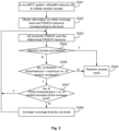
- In the following, the embodiment of the present disclosure will be described in detail with reference to various implementations shown in
Figs. 3 and4 . - It is to be noted that an eMTC FDD system is configured with four coverage levels, CEL0, CEL1, CEL2 and CEL3, among which CELO is the lowest coverage level. PRACH resource information for the four coverage levels is shown in Table 2.
Table 2 Coverage level PRACH config. index PRACH start subframe period PRACH frequency-domain offset Preamble codeword Threshold for no. of random accesses (with a total number of 20) CEL0 12 2 0 0-11 3 CEL1 9 4 0 12-23 3 CEL2 6 8 0 24-35 3 CEL3 3 16 0 36-37 3 - According to the 36.211 specification, the PRACH time-domain resources (radio frame numbers and subframe numbers) corresponding to the above PRACH configuration indices are shown in Table 3.
Table 3 PRACH config. index Radio frame No. Subframe No. 3 Any 1 6 Any 1, 6 9 Any 1, 4, 7 12 Any 0, 2, 4, 6, 8 - At step S301, in an eMTC system, an base station instructs a UE to initiate a random access (e.g., by transmitting a PDCCH order). The indicated PRACH resource information includes an initial coverage level and a subcarrier indication of NPRACH (i.e., subcarrier index). In the PDCCH order transmitted from the base station, the indicated PRACH information is shown in Table 4.
Table 4 eMTC Description Value Starting CE Level Coverage level at which UE transmits PRACH initially, i.e., UE initiates random access over a PRACH resource set corresponding to the coverage level initially CEL1 PRACH Mask Index Time-frequency resource index for UE to transmit PRACH 3 Preamble Index Preamble code to be used by UE for PRACH 15 - At step S302, the UE receives the PDCCH order, and obtains information on the initial coverage level and obtains a PRACH resource corresponding to the level, including a time-domain location, a frequency-domain location and a preamble codeword. The number of available PRACH time-frequency resources is NPRACH.
- For example, the UE obtains time-frequency resource information of a PRACH resource set and a number of repetitions based on the initial coverage level. The UE can calculate a PRACH sub-carrier ID to be used based on the subcarrier indication of NPRACH and the number of PRACH sub-carriers available at the initial coverage level.
- At step S303, the UE transmits PRACH over the determined PRACH resource.
- If the PRACH Mask Index (i.e., time-frequency resource index) transmitted from the base station is within a range of 1-10, the UE can calculate/determine a UE Mask Index (i.e., a target time-frequency resource index) to be used based on the PRACH Mask Index and the number of PRACH time-frequency resources (NPRACH), by means of mod operation:


- The number of PRACH time-frequency resources can be obtained from PRACH resource configuration according to the 36.211 specification.
- The definitions according to the 36.321 specification apply when the PRACH Mask Index field has other values.
- The UE can calculate the Preamble ID (i.e., target sub-carrier index) to be used based on the Preamble Index (code index) transmitted from the base station and the number of preamble codewords (NPreamble):


- The UE transmits the PRACH based on the PRACH and preamble code as determined above.
- At step S304, it is determined whether the random access has succeeded. If so, the method proceeds with step S306; otherwise the method proceeds with step S305.
- At step S305, if the initiated random access process has failed, PRACH is retransmitted over the determined PRACH resource. It is determined whether the number of PRACH transmissions at the initial coverage level is smaller than a maximum number of random accesses. If so, the method proceeds with step S307; otherwise the method proceeds with step S306.
- For example, the UE receives the PDCCH order, obtains the initial coverage level of CEL1 and the PRACH resource corresponding to CEL1. The PRACH configuration index is 9, i.e., the preamble code is to be transmitted in Subframes 1, 4 and 7 in each radio frame. The number, NPRACH, of PRACH resources available in this configuration is 3. The start subframe period for PRACH is 4 subframes. The start PRB of PRACH in the frequency domain is PRB=0. The number of preamble codes is 12, ranging from 12 to 23. The number of random accesses initiated at CEL1 is min(3, 20)=3.
- The UE calculates the UE Mask Index to be used based on the PRACH Mask Index indicated in the PDCCH order: UE Mask Index= (PRACH Mask Index-1) mod NPRACH +1=(3-1) mod 3+1=3. According to the 36.321 and 36.211 specifications, the preamble code is transmitted in Subframe 7 of each radio frame. Since the start subframe period for PRACH is 4 subframes, the UE transmits the preamble code in the subframe satisfying


- At step S306, the random access process ends.
- At step S307, it is determined whether the number of PRACH transmissions at the initial coverage level is smaller than the number of random accesses for this coverage level. If so, the method proceeds with step S303; otherwise the method proceeds with step S308.
- At step 308, if the number of PRACH transmissions at the current coverage level is equal to max(NumPreambleAttemptCE-r13) (i.e., the number of random accesses for the current coverage level) and smaller than num(RepetitionsPerPreambleAttempt-r13) (i.e., the maximum number of random accesses), the coverage level is increased by one level and the step S303 is performed again.
- The PRACH resource corresponding to the level is obtained, including a time-domain location, a frequency-domain location and a preamble codeword.
- The UE obtains time-frequency resource information of a PRACH resource set and a number of repetitions based on the current coverage level. The UE can calculate a PRACH sub-carrier ID to be used based on the subcarrier indication of NPRACH and the number of PRACH sub-carriers available at the current coverage level.
- The UE calculates the PRACH UE Mask Index and Preamble ID to be used at the new coverage level and transmits PRACH over the determined PRACH resource.
- For example, if the number of random accesses initiated at CEL1 is 3 (which has not reached the total number threshold of 20), the UE increases the coverage level to CEL2 and obtains the PRACH resource corresponding to the level. The PRACH configuration index is 6, i.e., the preamble code is to be transmitted in Subframes 1 and 6 in each radio frame. The number, Nprach, of PRACH resources available in this configuration is 2. The start subframe period for PRACH is 8 subframes. The start PRB of PRACH in the frequency domain is PRB=0. The number of preamble codes is 12, ranging from 24 to 35. The number of random accesses initiated at CEL2 is min(3, 20-3)=3.
- The UE calculates the UE Mask Index to be used based on the PRACH Mask Index indicated in the PDCCH order: UE Mask Index= (3-1) mod 2+1=1. According to the 36.321 and 36.211 specifications, the preamble code is transmitted in Subframe 1 of each radio frame. Since the start subframe period for PRACH is 8 subframes, the UE transmits the preamble code in the subframe satisfying

- Alternatively, the UE receives the PDCCH order, obtains the initial coverage level of CEL1 and the PRACH resource corresponding to CEL1. The PRACH configuration index is 9, i.e., the preamble code is to be transmitted in Subframes 1, 4 and 7 in each radio frame. The number, Nprach, of PRACH resources available in this configuration is 3. The start subframe period for PRACH is 4 subframes. The start PRB of PRACH in the frequency domain is PRB=0. The number of preamble codes is 12, ranging from 12 to 23. The number of random accesses initiated at CEL1 is min(3, 20)=3. The UE calculates the mask index to be used based on the PRACH Mask Index indicated in the PDCCH order: mask index= PRACH Mask Index mod Nprach +1=3 mod 3+1=1. According to the 36.321 and 36.211 specifications, mask index=3, i.e., the preamble code is transmitted in Subframe 7 of each radio frame. Since the start subframe period for PRACH is 4 subframes, the UE transmits the preamble code in the subframe satisfying (sf +

- The UE calculates the preamble index to be used based on the Preamble Index indicated in the PDCCH order: preamble index=12+Preamble Index mod 12 =12+15 mod 12=15. The UE transmits the preamble code 15 over the PRACH resource having PRB=0 in the determined subframe. If the initiated random access process fails and the number of random accesses initiated at CELO is smaller than 3, the preamble code 15 is retransmitted over the PRACH resource having PRB=0 in the subframe satisfying

- If the number of random accesses initiated at CEL1 is 3 (which has not reached the total number threshold of 20), the UE increases the coverage level to CEL2 and obtains the PRACH resource corresponding to the level. The PRACH configuration index is 6, i.e., the preamble code is to be transmitted in Subframes 1 and 6 in each radio frame. The number, NPRACH, of PRACH resources available in this configuration is 2. The start subframe period for PRACH is 8 subframes. The start PRB of PRACH in the frequency domain is PRB=0. The number of preamble codes is 12, ranging from 24 to 35. The number of random accesses initiated at CEL2 is min(3, 20-3)=3.
- The UE calculates the mask index to be used based on the PRACH Mask Index indicated in the PDCCH order: mask index = (PRACH Mask Index-1) mod NPRACH +1=(3-1) mod 2+1=1. According to the 36.321 and 36.211 specifications, mask index=1, i.e., the preamble code is transmitted in Subframe 1 of each radio frame.
- Since the start subframe period for PRACH is 8 subframes, the UE transmits the preamble code in the subframe satisfying

- The UE calculates the preamble index to be used based on the Preamble Index indicated in the PDCCH order: preamble index=24+Preamble Index mod 12 =24+15 mod 12=27. The UE transmits the preamble code 27 over the PRACH resource having PRB=0 in the determined subframe. The above steps are repeated until the random access succeeds or until the maximum number of repetitions min(3+3+3,20)=9 is reached.
- It is to be noted that an NB-IoT system is configured with three coverage levels, CEL0, CEL1 and CEL2, among which CELO is the lowest coverage level. PRACH resource information for the three coverage levels is shown in Table 5.
Table 5 Coverage level PRACH period PRACH start subframe offset PRACH sub-carrier Threshold for no. of random accesses (with a total number of 20) CEL0 640ms 8ms 0-11 3 CEL1 640ms 64ms 12-23 3 CEL2 640ms 256ms 24-35 3 - At step S401, in an NB-IoT system, an base station transmits a PDCCH order indicating PRACH information as shown in Table 6, including a "Starting number of NPRACH repetitions" field and a "Subcarrier indication of NPRACH" field.
Table 6 Description Value Starting number of NPRACH repetitions Coverage level at which UE transmits PRACH initially, i.e., UE initiates random access over a PRACH CEL0 resource set corresponding to the coverage level initially Subcarrier indication of NPRACH Frequency-domain sub-carrier ID (NB-IoT) for UE to transmit PRACH 6 - At step S402, the UE receives the PDCCH order, and obtains information on the initial coverage level and obtains a PRACH resource corresponding to the level, including a time-domain location and a frequency-domain location. Here, the frequency-domain location can be determined based on two parameters: nprach-SubcarrierOffset-r13 (an index of the first subcarrier allocated to PRACH) and nprach-NumSubcarriers-r13.
- For example, the initial coverage level of CELO and the PRACH resource corresponding to CELO can be obtained. Its period is 640ms, the start subframe offset is 8 and the number of sub-carriers is 12, ranging from 0 to 11. The number of random accesses initiated at CELO is min(3, 20)=3. The UE can calculate the sub-carrier ID to be used at CELO based on the indicated Subcarrier indication of NPRACH. The calculation can include but not limited to:

- Ata step S403, when the end subframe of the PDCCH order is n, the UE transmits PRACH over the determined PRACH resource, starting from the subframe having an index of n+9.
- For example, the UE transmits a PRACH signal, starting from a subframe satisfying


- At step S404, it is determined whether the random access has succeeded. If so, the method proceeds with step S406; otherwise the method proceeds with step S405.
- If the number of random accesses initiated at CELO is 3 (which has not reached the total number threshold of 20), the UE increases the coverage level to CEL1 and obtains the PRACH resource corresponding to the level. Its period is 640ms, the start subframe offset is 64 and the number of sub-carriers is 12, ranging from 12 to 23. The number of random accesses initiated at CEL1 is min(3, 20-3)=3.
- At step S405, if the initiated random access process has failed, PRACH is retransmitted over the determined PRACH resource. It is determined whether the number of PRACH transmissions at the initial coverage level is smaller than a maximum number of random accesses. If so, the method proceeds with step S407; otherwise the method proceeds with step S406.
- At step S406, the random access process ends.
- At step S407, it is determined whether the number of PRACH transmissions at the initial coverage level is smaller than the number of random accesses for this coverage level. If so, the method proceeds with step S403; otherwise the method proceeds with step S408.
- At
step 408, if the number of PRACH transmissions at the current coverage level is equal to max(NumPreambleAttemptCE-r13) (i.e., the number of random accesses for the current coverage level) and smaller than num(RepetitionsPerPreambleAttempt-r13) (i.e., the maximum number of random accesses), the coverage level is increased by one level, the PRACH resource corresponding to the level is obtained, including a time-domain location, a frequency-domain location and a number of repetitions, and the step S403 is performed again. - The UE calculates the PRACH sub-carrier ID to be used at the new coverage level.
- The UE transmits PRACH over the re-determined PRACH resource.
- For example, the UE can calculate the sub-carrier ID to be used at CEL1 based on the indicated Subcarrier indication of NPRACH. The calculation can include but not limited to: PRACH sub-carrier ID=12+6 mod 12=18. The UE retransmits the PRACH signal, starting from a subframe satisfying

- The above steps are repeated until the random access succeeds or until the maximum number of repetitions min(3+3+3,20)=9 is reached.
- With the description of the above embodiments, it will be apparent to those skilled in the art that the method according to the above embodiments can be realized by means of software plus the necessary general hardware platform, and of course can be implemented via hardware, but in many cases the former is the better implementation. Based on this understanding, the technical solution of the present disclosure, in essence or in terms of parts contributing to the prior art, can be embodied in the form of a software product, which is stored in a storage medium (e.g., ROM/RAM, disc, CD-ROM) and includes a number of instructions for enabling a terminal device (which may be a mobile phone, a computer, a server, or a network device, etc.) to perform the method described in the various embodiments of the present disclosure.
- It is to be noted that an NB-IoT system is configured with three coverage levels, CEL0, CEL1 and CEL2, among which CELO is the lowest coverage level. PRACH resource information for the three coverage levels is shown in Table 7.
Table 7 Coverage level PRACH period PRACH start subframe offset PRACH sub-carrier Threshold for no. of random accesses (with a total number of 20) CEL0 640ms 8ms 0-11 3 CEL1 640ms 64ms 12-23 3 CEL2 640ms 256ms 24-35 3 - At step S401, in an NB-IoT system, an base station transmits a PDCCH order indicating PRACH information as shown in Table 8, including a "Starting number of NPRACH repetitions" field and a "Subcarrier indication of NPRACH" field.
Table 8 Description Value Starting number of NPRACH repetitions Coverage level at which UE transmits PRACH initially, i.e., UE initiates random access over a PRACH resource set corresponding to the coverage level initially CEL0 Subcarrier indication of NPRACH Frequency-domain sub-carrier ID (NB-IoT) for UE to transmit PRACH 6 - At step S402, the UE receives the PDCCH order, and obtains information on the initial coverage level and obtains a PRACH resource corresponding to the level, including a time-domain location and a frequency-domain location. Here, the frequency-domain location can be determined based on two parameters: nprach-SubcarrierOffset-r13 (PRACH start sub-carrier) and nprach-NumSubcarriers-r13.
- For example, the initial coverage level of CELO and the PRACH resource corresponding to CELO can be obtained. Its period is 640ms, the start subframe offset is 8 and the number of sub-carriers is 12, ranging from 0 to 11. The number of random accesses initiated at CELO is min(3, 20)=3. The UE can calculate the sub-carrier ID to be used at CELO based on the indicated Subcarrier indication of NPRACH. The calculation can include but not limited to:

- Ata step S403, when the end subframe of the PDCCH order is n, the UE transmits PRACH over the determined PRACH resource, starting from the subframe having an index of n+9.
- For example, the UE transmits a PRACH signal, starting from a subframe satisfying


- At step S404, it is determined whether the random access has succeeded. If so, the method proceeds with step S406; otherwise the method proceeds with step S405.
- If the number of random accesses initiated at CELO is 3 (which has not reached the total number threshold of 20), the UE increases the coverage level to CEL1 and obtains the PRACH resource corresponding to the level. Its period is 640ms, the start subframe offset is 64 and the number of sub-carriers is 12, ranging from 12 to 23. The number of random accesses initiated at CEL1 is min(3, 20-3)=3.
- At step S405, if the initiated random access process has failed, PRACH is retransmitted over the determined PRACH resource. It is determined whether the number of PRACH transmissions at the initial coverage level is smaller than a maximum number of random accesses. If so, the method proceeds with step S407; otherwise the method proceeds with step S406.
- At step S406, the random access process ends.
- At step S407, it is determined whether the number of PRACH transmissions at the initial coverage level is smaller than the number of random accesses for this coverage level. If so, the method proceeds with step S403; otherwise the method proceeds with step S408.
- At
step 408, if the number of PRACH transmissions at the current coverage level is equal to max(NumPreambleAttemptCE-r13) (i.e., the number of random accesses for the current coverage level) and smaller than num(RepetitionsPerPreambleAttempt-r13) (i.e., the maximum number of random accesses), the coverage level is increased by one level, the PRACH resource corresponding to the level is obtained, including a time-domain location, a frequency-domain location and a number of repetitions, and the step S403 is performed again. - The UE calculates the PRACH sub-carrier ID to be used at the new coverage level.
- The UE transmits PRACH over the re-determined PRACH resource.
- For example, the UE can calculate the sub-carrier ID to be used at CEL1 based on the indicated Subcarrier indication of NPRACH. The calculation can include but not limited to: PRACH sub-carrier ID=12+(6-0) mod 12=18. The UE retransmits the PRACH signal, starting from a subframe satisfying

- The above steps are repeated until the random access succeeds or until the maximum number of repetitions min(3+3+3,20)=9 is reached.
- After the multi-carrier enhancement technique has been introduced in NB-IoT Rel-14, it is allowed to initiate a random access in anchor carrier(s) and non-anchor carrier(s). PRACH carriers available for random access are configured at each coverage level. For a base station initiated random access process, in addition to the above PRACH resource information, the base station indicates a PRACH carrier for a terminal to initiate random access. When the coverage level needs to be increased after the terminal has failed to initiate the random access at the initial coverage level indicated by the base station, the PRACH carrier indicated by the base station may not be included in the set of PRACH resources for the higher level. In this case, the UE would not be able to initiate a random access or the UE transmits a PRACH signal over the PRACH resource indicated by the base station but the base station would not respond. In either case, the random access will fail, resulting in a reduced success rate of the base station initiated random accesses and loss of uplink synchronization of the terminal.
- Optionally, the target PRACH resource further includes a target carrier for transmitting the PRACH signal. The operation of mapping the resource information to the target PRACH resource from resources available at the current coverage level includes: determining the target carrier based on a list of carriers at the current coverage level and a carrier index in the resource information.
- Optionally, the operation of determining the target carrier based on the list of carriers at the current coverage level and the carrier index in the resource information includes: determining a list of target carriers at the current coverage level based on a list of non-anchor carriers configured by the system and PRACH resource configurations for different coverage levels on each carrier, wherein the list of non-anchor carriers stores first non-anchor carriers, a second non-anchor carrier in the list of target carriers is included in the list of non-anchor carriers, and each carrier in the list of target carriers has an index; calculating a fourth index, ID12, based on a number, Num4, of carriers in the list of target carriers and the carrier index, ID11, as ID12=(ID11)mod(Num4), wherein the carrier index ID 11 is an index for searching for the target carrier; and determining a carrier having the index of ID12 in the list of target carriers as the target carrier.
- Each non-anchor carrier is configured by the system with PRACH resources corresponding to the respective coverage levels. According to the order in the list of non-anchor carriers configured by the system, the non-anchor carriers each configured with the PRACH resource for the current coverage level are organized, in their sequence in the list of non-anchor carriers, into the list of target carriers.
- Optionally, when the carrier index ID 11 is not equal to a predetermined threshold, each of the first non-anchor carriers in the list of the non-anchor carriers has a carrier sequence number, an anchor carrier at the head of the list of target carriers has a carrier sequence number of 0, and the second non-anchor carrier has a same carrier sequence number as a carrier, from which the second non-anchor carrier originates, in the list of the non-anchor carriers.
- Optionally, when the carrier index ID 11 is not equal to a predetermined threshold, an anchor carrier at the head of the list of target carriers has a carrier sequence number of 0, and the second non-anchor carrier has a carrier sequence number that is the same as the index of the second non-anchor carrier.
- Optionally, when the carrier index ID 11 is not equal to a predetermined threshold, each of the first non-anchor carriers in the list of the non-anchor carriers has a carrier sequence number, an anchor carrier at the end of the list of target carriers has a carrier sequence number of 0, and the second non-anchor carrier has a same carrier sequence number as a carrier, from which the second non-anchor carrier originates, in the list of the non-anchor carriers.
- Optionally, when the carrier index ID 11 is equal to a predetermined threshold, each of the first non-anchor carriers in the list of the non-anchor carriers has a carrier sequence number, and, in the list of target carriers, the second non-anchor carrier has a same carrier sequence number as a carrier, from which the second non-anchor carrier originates, in the list of the non-anchor carriers. The list of target carriers includes no anchor carrier.
- Optionally, when the carrier index ID 11 is equal to a predetermined threshold, in the list of target carriers, the second non-anchor carrier has a carrier sequence number that is the same as the index of the second non-anchor carrier. The list of target carriers includes no anchor carrier.
- Optionally, when the carrier index ID 11 is equal to a predetermined threshold, an anchor carrier is the target carrier. The predetermined threshold indicates the anchor carrier as the target carrier.
- The operation of determining the target carrier based on the list of carriers at the current coverage level includes: determining a list, A, of available carriers at the current coverage level based on the list of non-anchor carriers configured by the system, {non-anchor carrier ID1, non-anchor carrier ID2, ...}, and PRACH resource configurations for respective coverage levels on each carrier. The carriers in the list A are arranged in the order of {anchor carrier, non-anchor carrier n1, non-anchor carrier n2, ...}. Indices 0, 1, 2, ... are assigned to the carriers in the list A in that order. The anchor carrier has a carrier ID of 0. The carrier IDs of non-anchor carrier n1, non-anchor carrier n2, ... are carrier IDs of the respective non-anchor carriers in the list of non-anchor carriers configured by the system, in the order that is the same as, or conforms to, the order in the list of non-anchor carriers configured by the system. The fourth index ID12 is calculated based on the number Num4 of carriers in the list A of carriers and the carrier index ID11, as ID12=(ID11)mod(Num4). A carrier having the index of ID12 in the list A of carriers is determined as the target carrier.
- Alternatively, a list, A, of available carriers at the current coverage level can be determined based on the list of non-anchor carriers configured by the system, {non-anchor carrier ID1, non-anchor carrier ID2, ...}, and PRACH resource configurations for respective coverage levels on each carrier. The carriers in the list A are arranged in the order of {anchor carrier, non-anchor carrier n1, non-anchor carrier n2, ...}. Indices 0, 1, 2, ... are assigned to the carriers in the list A in that order. The carrier IDs of the anchor carrier, non-anchor carrier n1, non-anchor carrier n2, ... are their respective indices. The order of non-anchor carrier n1, non-anchor carrier n2, ... is the same as the order in the list of non-anchor carriers configured by the system. The fourth index ID12 is calculated based on the number Num4 of carriers in the list A of carriers and the carrier index ID11, as ID12=(ID11)mod(Num4). A carrier having the index of ID12 in the list A of carriers is determined as the target carrier.
- Alternatively, a list, A, of available carriers at the current coverage level can be determined based on the list of non-anchor carriers configured by the system, {non-anchor carrier ID1, non-anchor carrier ID2, ...}, and PRACH resource configurations for respective coverage levels on each carrier. The carriers in the list A are arranged in the order of { non-anchor carrier n1, non-anchor carrier n2, ..., anchor carrier}. Indices 0, 1, 2, ... are assigned to the carriers in the list A in that order. The anchor carrier has a carrier ID of 0. The carrier IDs of non-anchor carrier n1, non-anchor carrier n2, ... are carrier IDs of the respective non-anchor carriers in the list of non-anchor carriers configured by the system, in the order that is the same as, or conforms to, the order in the list of non-anchor carriers configured by the system. The fourth index ID12 is calculated based on the number Num4 of carriers in the list A of carriers and the carrier index ID11, as ID12=(ID11)mod(Num4). A carrier having the index of ID12 in the list A of carriers is determined as the target carrier.
- Alternatively, if the carrier index ID11 is a particular value, the anchor carrier is determined as the target sub-carrier. If the carrier index ID11 is not the particular value, a list, A, of available carriers at the current coverage level can be determined based on the list of non-anchor carriers configured by the system, {non-anchor carrier ID1, non-anchor carrier ID2, ...}, and PRACH resource configurations for respective coverage levels on each carrier. The carriers in the list A are arranged in the order of { non-anchor carrier n1, non-anchor carrier n2, ...}. Indices 0, 1, 2, ... are assigned to the carriers in the list A in that order. The anchor carrier has a carrier ID of 0. The carrier IDs of non-anchor carrier n1, non-anchor carrier n2, ... are carrier IDs of the respective non-anchor carriers in the list of non-anchor carriers configured by the system, in the order that is the same as, or conforms to, the order in the list of non-anchor carriers configured by the system. The fourth index ID12 is calculated based on the number Num4 of carriers in the list A of carriers and the carrier index ID11, as ID12=(ID11)mod(Num4). A carrier having the index of ID12 in the list A of carriers is determined as the target carrier.
- Alternatively, if the carrier index ID11 is a particular value, the anchor carrier is determined as the target sub-carrier. If the carrier index ID11 is not the particular value, a list, A, of available carriers at the current coverage level can be determined based on the list of non-anchor carriers configured by the system, {non-anchor carrier ID1, non-anchor carrier ID2, ...}, and PRACH resource configurations for respective coverage levels on each carrier. The carriers in the list A are arranged in the order of {anchor carrier, non-anchor carrier n1, non-anchor carrier n2, ...}. Indices 0, 1, 2, ... are assigned to the carriers in the list A in that order. The carrier IDs of non-anchor carrier n1, non-anchor carrier n2, ... are their respective indices. The order of non-anchor carrier n1, non-anchor carrier n2, ... is the same as the order in the list of non-anchor carriers configured by the system. The fourth index ID12 is calculated based on the number Num4 of carriers in the list A of carriers and the carrier index ID11, as ID12=(ID11)mod(Num4). A carrier having the index of ID12 in the list A of carriers is determined as the target carrier.
- Table 9 shows PRACH information indicated in a PDCCH order according to NB-IoT Rel-14 standard protocol.
Table 9 NB-IoT Description Starting number of NPRACH repetitions Coverage level at which UE transmits PRACH initially, i.e., UE initiates random access over a PRACH resource set corresponding to the coverage level initially Subcarrier indication of NPRACH Frequency-domain sub-carrier ID (NB-IoT) for UE to transmit PRACH PRACH carrier Index Carrier index for UE to transmit PRACH initially - In the NB-IoT system, for a Rel-13 terminal, it transmits a PRACH signal on an anchor carrier and determines the sub-carrier for transmission of PRACH. For a Rel-14 terminal, it determines the PRACH carrier for transmission of a PRACH signal at the current coverage level based on the "PRACH carrier Index" field indicated by the base station, in accordance with the following non-limiting schemes.
-
- 1) All PRACH carriers available for transmitting the PRACH signal at the current coverage level are determined. If there is an anchor carrier, it will be numbered as 0 and non-anchor carriers will be numbered sequentially, starting from 1, according to their orders in a list of non-anchor carriers in a broadcast message. If there is no anchor carrier, non-anchor carriers will be numbered sequentially, starting from 0, according to their orders in a list of non-anchor carriers in a broadcast message. The numbers are denoted as index1, and the maximum number +1 is the number, Nprach_carrier, of PRACH carriers available for transmitting the PRACH signal at the current coverage level. The number is denoted as index1, and the maximum number is the number, Nprach_carrier, of PRACH carriers available for transmitting the PRACH signal at the current coverage level.
- 2) The PRACH carrier to be used at the current coverage level is determined as: index2 = index1 mod Nprach_carrier.
- 3) The PRACH carrier having the value of index2 in index1 is determined as the PRACH carrier to be used by the terminal for transmitting the PRACH signal.
-
- 1) All PRACH carriers available for transmitting the PRACH signal at the current coverage level are determined. Non-anchor carriers are numbered sequentially, starting from 0, according to their orders in a list of non-anchor carriers in a broadcast message. The maximum number is Nnon-anchor. If there is an anchor carrier, it will be numbered as Nnon-anchor+1. The numbers are denoted as index1, and the maximum number +1 is the number, Nprach_carrier, of PRACH carriers available for transmitting the PRACH signal at the current coverage level.
- 2) The PRACH carrier to be used at the current coverage level is determined as: index2 = index1 mod Nprach_carrier.
- 3) The PRACH carrier having the value of index2 in index1 is determined as the PRACH carrier to be used by the terminal for transmitting the PRACH signal.
-
- 1) If PRACH carrier Index indicated by the system is a particular value (e.g., 0 or 15), it indicates that the PRACH signal is to be transmitted on an anchor carrier. The terminal transmits the PRACH signal only on the anchor carrier.
- 2) If PRACH carrier Index indicated by the system is not the particular value, all non-anchor carriers available for transmitting the PRACH signal at the current coverage level are determined. Non-anchor carriers are numbered sequentially, starting from 0, according to their orders in a list of non-anchor carriers in a broadcast message. The numbers are denoted as index1, and the maximum number +1 is the number, Nprach_carrier, of PRACH carriers available for transmitting the PRACH signal at the current coverage level.
- 3) The PRACH carrier to be used at the current coverage level is determined as: index2 = index1 mod Nprach_carrier.
- 4) The PRACH carrier having the value of index2 in index1 is determined as the PRACH carrier to be used by the terminal for transmitting the PRACH signal.
-
- 1) If PRACH carrier Index indicated by the system is a particular value of 0, it indicates that the PRACH signal is to be transmitted on an anchor carrier. The terminal transmits the PRACH signal only on the anchor carrier.
- 2) If PRACH carrier Index indicated by the system is not the particular value, all non-anchor carriers available for transmitting the PRACH signal at the current coverage level are determined. The anchor carrier is numbered as 0. The non-anchor carriers are numbered sequentially, starting from 1, according to their orders in a list of non-anchor carriers in a broadcast message. The numbers are denoted as index1, and the maximum number is the number, Nprach_carrier, of PRACH carriers available for transmitting the PRACH signal at the current coverage level.
- 3) The PRACH carrier to be used at the current coverage level is determined as: index2 = 1+index1 mod Nprach_carrier.
- 4) The PRACH carrier having the value of index2 in index1 is determined as the PRACH carrier to be used by the terminal for transmitting the PRACH signal.
- An optional embodiment is described below.
- An NB-IoT system is configured with three coverage levels, CEL0, CEL1 and CEL2, among which CELO is the lowest coverage level. An NB-IoT cell is configured with one anchor carrier and three non-anchor carriers. The PRACH resource information for these five carriers is shown in Table 10, which gives PRACH information configured by means of NB-IoT system broadcast.
Table 10 Carrier ID Coverage level PRACH period PRACH start subframe offset PRACH sub-carrier Threshold for no. of random accesses (with a total number of 20) Anchor carrier CEL0 640ms 8ms 0-11 3 CEL1 640ms 64ms 12-23 3 CEL2 640ms 256ms 24-35 3 Non-anchor carrier 1 CEL0 640ms 8ms 0-11 3 CEL1 640ms 64ms 12-23 3 CEL2 640ms 256ms 24-35 3 Non-anchor carrier 2 CEL0 640ms 8ms 0-11 3 CEL1 640ms 64ms 12-23 3 Non-anchor carrier 3 CEL0 640ms 8ms 0-11 3 - A base station transmits a PDCCH order indicating PRACH information as shown in Table 11.
Table 11 Description Value Starting number of NPRACH repetitions Coverage level at which UE transmits PRACH initially, i.e., UE initiates random access over a PRACH resource set corresponding to the coverage level initially CEL0 Subcarrier indication of NPRACH Frequency-domain sub-carrier ID (NB-IoT) for UE to transmit PRACH 6 PRACH carrier Index Carrier index for UE to transmit PRACH initially 3 - A Rel-14 UE receives the PDCCH order, obtains an initial coverage level of CELO and PRACH resource information corresponding to CEL0. The PRACH resource information corresponding to CELO is shown in Table 12.
Table 12 Carrier ID Coverage level PRACH period PRACH start subframe offset PRACH sub-carrier Threshold for no. of random accesses (with a total number of 20) Anchor carrier CEL0 640ms 8ms 0-11 3 Non-anchor carrier 1 CEL0 640ms 8ms 0-11 3 Non-anchor carrier 2 CEL0 640ms 8ms 0-11 3 Non-anchor carrier 3 CEL0 640ms 8ms 0-11 3 - The anchor carrier is numbered as 0. The non-anchor carriers are numbered, starting from 1, according to their orders in a list of carriers configured by system broadcast. The non-anchor carrier 1 is numbered as 1, the non-anchor carrier 2 is numbered as 2, and the non-anchor carrier 3 is numbered as 3. A list of the numbers 0-3 is denoted as index1, i.e., index1=[0,1,2,3], corresponding to {anchor carrier, non-anchor carrier 1, non-anchor carrier 2, non-anchor carrier 3}. Meanwhile, it knows that the number of PRACH carriers at CELO is 4.
- The UE determines the PRACH carrier index to be used at CELO based on the indicated PRACH carrier Index: index2=PRACH carrier Index mod 4=3 mod 4 =3.
- The carrier having an index of 3 in index1, i.e., the non-anchor carrier 3, is determined as the PRACH carrier to be used by the UE for transmitting the PRACH signal.
- On the non-anchor carrier 3, the UE calculates the sub-carrier ID to be used at CELO based on the indicated Subcarrier indication of NPRACH, according to, as a non-limiting example:

- The UE transmits the PRACH signal, starting from a subframe satisfying (sf + ns2mod 640=8, using a sub-carrier ID of 6 on the non-anchor carrier 3, where sf is a radio frame number and ns is a slot number.
- If the initiated random access process fails and the number of random accesses initiated at CELO is smaller than 3, the PRACH signal is retransmitted, starting from a subframe satisfying

- If the number of random accesses initiated at CELO is 3 (which has not reached the total number threshold of 20), the UE increases the coverage level to CEL1 and obtains the PRACH resource corresponding to the level, as shown in Table 13.
Table 13 Carrier ID Coverage level PRACH period PRACH start subframe offset PRACH sub-carrier Threshold for no. of random accesses (with a total number of 20) Anchor carrier CEL1 640ms 64ms 12-23 3 Non-anchor carrier 1 CEL1 640ms 64ms 12-23 3 Non-anchor carrier 2 CEL1 640ms 64ms 12-23 3 - The anchor carrier is numbered as 0. The non-anchor carriers are numbered, starting from 1, according to their orders in a list of carriers configured by system broadcast. The non-anchor carrier 1 is numbered as 1 and the non-anchor carrier 2 is numbered as 2. A list of the numbers 0-2 is denoted as index1, i.e., index1=[0,1,2], corresponding to {anchor carrier, non-anchor carrier 1, non-anchor carrier 2}. Meanwhile, it knows that the number of PRACH carriers at CELO is 3.
- The UE determines the PRACH carrier index to be used at CEL1 based on the indicated PRACH carrier Index: index2=PRACH carrier Index mod 3=3 mod 3 =0.
- The carrier having an index of 0 in index1, i.e., the anchor carrier, is determined as the PRACH carrier to be used by the UE for transmitting the PRACH signal.
- On the anchor carrier, the UE calculates the sub-carrier ID to be used at CEL1 based on the indicated Subcarrier indication of NPRACH, according to, as a non-limiting example:

- The UE retransmits the PRACH signal, starting from a subframe satisfying

- The above steps are repeated until the random access succeeds or until the maximum number of repetitions min(3+3+3,20)=9 is reached.
- A further optional example is provided according to this embodiment.
- An NB-IoT system is configured with three coverage levels, CEL0, CEL1 and CEL2, among which CELO is the lowest coverage level. An NB-IoT cell is configured with one anchor carrier and three non-anchor carriers. The PRACH resource information for these five carriers is shown in Table 14.
Table 14 Carrier ID Coverage level PRACH period PRACH start subframe offset PRACH sub-carrier Threshold for no. of random accesses (with a total number of 20) Anchor carrier CEL0 640ms 8ms 0-11 3 CEL1 640ms 64ms 12-23 3 CEL2 640ms 256ms 24-35 3 Non-anchor carrier 1 CEL0 640ms 8ms 0-11 3 CEL1 640ms 64ms 12-23 3 CEL2 640ms 256ms 24-35 3 Non-anchor carrier 2 CEL0 640ms 8ms 0-11 3 CEL1 640ms 64ms 12-23 3 Non-anchor carrier 3 CEL0 640ms 8ms 0-11 3 - An base station transmits a PDCCH order indicating PRACH information as shown in Table 15. Table 15 shows the PRACH information indicated in the PDCCH order transmitted in NB-IoT.
Table 15 Description Value Starting number of NPRACH repetitions Coverage level at which UE transmits PRACH initially, i.e., UE initiates random access over a PRACH resource set corresponding to the coverage level initially CEL0 Subcarrier indication of NPRACH Frequency-domain sub-carrier ID (NB-IoT) for UE to transmit PRACH 6 PRACH carrier Index Carrier index for UE to transmit PRACH initially 3 - A Rel-14 UE receives the PDCCH order. The indicated PRACH carrier Index is not a particular value (assumed to be 0). Then, the UE obtains an initial coverage level of CELO and PRACH resource information for non-anchor carriers corresponding to CEL0. The PRACH resource information for non-anchor carriers corresponding to CELO is shown in Table 16.
Table 16 Carrier ID Coverage level PRACH period PRACH start subframe offset PRACH sub-carrier Threshold for no. of random accesses (with a total number of 20) Non-anchor carrier 1 CEL0 640ms 8ms 0-11 3 Non-anchor carrier 2 CEL0 640ms 8ms 0-11 3 Non-anchor carrier 3 CEL0 640ms 8ms 0-11 3 - The non-anchor carriers are numbered, starting from 0, according to their orders in a list of carriers configured by system broadcast. The non-anchor carrier 1 is numbered as 0, the non-anchor carrier 2 is numbered as 1, and the non-anchor carrier 3 is numbered as 2. A list of the numbers 0-2 is denoted as index1, i.e., index1=[0,1,2], corresponding to { non-anchor carrier 1, non-anchor carrier 2, non-anchor carrier 3}. Meanwhile, it knows that the number of non-anchor PRACH carriers at CELO is 3.
- The UE determines the non-anchor PRACH carrier index to be used at CELO based on the indicated PRACH carrier Index: index2=PRACH carrier Index mod 3=3 mod 3 =0.
- The carrier having an index of 0 in index1, i.e., the non-anchor carrier 1, is determined as the PRACH carrier to be used by the UE for transmitting the PRACH signal.
- On the non-anchor carrier 1, the UE calculates the sub-carrier ID to be used at CELO based on the indicated Subcarrier indication of NPRACH, according to, as a non-limiting example:

- The UE transmits the PRACH signal, starting from a subframe satisfying (sf + ns2mod 640=8, using a sub-carrier ID of 6 on the non-anchor carrier 1, where sf is a radio frame number and ns is a slot number.
- If the initiated random access process fails and the number of random accesses initiated at CELO is smaller than 3, the PRACH signal is retransmitted, starting from a subframe satisfying

- If the number of random accesses initiated at CELO is 3 (which has not reached the total number threshold of 20), the UE increases the coverage level to CEL1 and obtains the non-anchor PRACH resource corresponding to the level, as shown in Table 17.
Table 17 Carrier ID Coverage level PRACH period PRACH start subframe offset PRACH sub-carrier Threshold for no. of random accesses (with a total number of 20) Non-anchor carrier 1 CEL1 640ms 64ms 12-23 3 Non-anchor carrier 2 CEL1 640ms 64ms 12-23 3 - The non-anchor carriers are numbered, starting from 0, according to their orders in a list of carriers configured by system broadcast. The non-anchor carrier 1 is numbered as 0 and the non-anchor carrier 2 is numbered as 1. A list of the numbers 0-1 is denoted as index1, i.e., index1=[0,1], corresponding to { non-anchor carrier 1, non-anchor carrier 2}. Meanwhile, it knows that the number of non-anchor PRACH carriers at CELO is 2.
- The UE determines the PRACH carrier index to be used at CEL1 based on the indicated PRACH carrier Index: index2=PRACH carrier Index mod 2=3 mod 2 =1.
- The carrier having an index of 1 in index1, i.e., the non-anchor carrier 2, is determined as the PRACH carrier to be used by the UE for transmitting the PRACH signal.
- On the non-anchor carrier 2, the UE calculates the sub-carrier ID to be used at CEL1 based on the indicated Subcarrier indication of NPRACH, according to, as a non-limiting example:

- The UE retransmits the PRACH signal, starting from a subframe satisfying

- The above steps are repeated until the random access succeeds or until the maximum number of repetitions min(3+3+3,20)=9 is reached.
- A further optional example is provided according to the present disclosure.
- An NB-IoT system is configured with three coverage levels, CEL0, CEL1 and CEL2, among which CELO is the lowest coverage level. An NB-IoT cell is configured with one anchor carrier and three non-anchor carriers. The PRACH resource information for these five carriers is shown in Table 18, which gives PRACH information configured by means of NB-IoT system broadcast.
Table 18 Carrier ID Coverage level PRACH period PRACH start subframe offset PRACH sub-carrier Threshold for no. of random accesses (with a total number of 20) Anchor carrier CEL0 640ms 8ms 0-11 3 CEL1 640ms 64ms 12-23 3 CEL2 640ms 256ms 24-35 3 Non-anchor carrier 1 CEL0 640ms 8ms 0-11 3 CEL1 640ms 64ms 12-23 3 CEL2 640ms 256ms 24-35 3 Non-anchor carrier 2 CEL0 640ms 8ms 0-11 3 CEL1 640ms 64ms 12-23 3 Non-anchor carrier 3 CEL0 640ms 8ms 0-11 3 - An base station transmits a PDCCH order indicating PRACH information as shown in Table 19. Table 19 shows the PRACH information indicated in the PDCCH order transmitted in NB-IoT.
Table 19 Description Value Starting number of NPRACH repetitions Coverage level at which UE transmits PRACH initially, i.e., UE initiates random access over a PRACH resource set corresponding to the coverage level initially CEL0 Subcarrier indication of NPRACH Frequency-domain sub-carrier ID (NB-IoT) for UE to transmit PRACH 6 PRACH carrier Index Carrier index for UE to transmit PRACH initially 3 - A Rel-14 UE receives the PDCCH order. The indicated PRACH carrier Index is not a particular value (assumed to be 0). Then, the UE obtains an initial coverage level of CELO and PRACH resource information for non-anchor carriers corresponding to CEL0. The PRACH resource information for non-anchor carriers corresponding to CELO is shown in Table 20.
Table 20 Carrier ID Coverage level PRACH period PRACH start subframe offset PRACH sub-carrier Threshold for no. of random accesses (with a total number of 20) Non-anchor carrier 1 CEL0 640ms 8ms 0-11 3 Non-anchor carrier 2 CEL0 640ms 8ms 0-11 3 Non-anchor CEL0 640ms 8ms 0-11 3 carrier 3 - The anchor carrier is numbered as 0. The non-anchor carriers are numbered, starting from 1, according to their orders in a list of carriers configured by system broadcast. The non-anchor carrier 1 is numbered as 1, the non-anchor carrier 2 is numbered as 2, and the non-anchor carrier 3 is numbered as 3. A list of the numbers 0-3 is denoted as index1, i.e., index1=[0,1,2,3], corresponding to {anchor carrier, non-anchor carrier 1, non-anchor carrier 2, non-anchor carrier 3}. Meanwhile, it knows that the number of non-anchor PRACH carriers at CELO is 3.
- The UE determines the non-anchor PRACH carrier index to be used at CELO based on the indicated PRACH carrier Index: index2=1+PRACH carrier Index mod 3=1+3 mod 3 =1.
- The carrier having an index of 1 in index1, i.e., the non-anchor carrier 1, is determined as the PRACH carrier to be used by the UE for transmitting the PRACH signal.
- On the non-anchor carrier 1, the UE calculates the sub-carrier ID to be used at CELO based on the indicated Subcarrier indication of NPRACH, according to, as a non-limiting example:

- The UE transmits the PRACH signal, starting from a subframe satisfying (sf + ns2mod 640=8, using a sub-carrier ID of 6 on the non-anchor carrier 1, where sf is a radio frame number and ns is a slot number.
- If the initiated random access process fails and the number of random accesses initiated at CELO is smaller than 3, the PRACH signal is retransmitted, starting from a subframe satisfying

- If the number of random accesses initiated at CELO is 3 (which has not reached the total number threshold of 20), the UE increases the coverage level to CEL1 and obtains the non-anchor PRACH resource corresponding to the level. Table 21 shows the PRACH resource information for non-anchor carriers at CEL1.
Table 21 Carrier ID Coverage level PRACH period PRACH start subframe offset PRACH sub-carrier Threshold for no. of random accesses (with a total number of 20) Non-anchor carrier 1 CEL1 640ms 64ms 12-23 3 Non-anchor carrier 2 CEL1 640ms 64ms 12-23 3 - The non-anchor carriers are numbered, starting from 0, according to their orders in a list of carriers configured by system broadcast as shown in Table 5. The non-anchor carrier 1 is numbered as 0 and the non-anchor carrier 2 is numbered as 1. A list of the numbers 0-1 is denoted as index1, i.e., index1=[0,1], corresponding to { non-anchor carrier 1, non-anchor carrier 2}. Meanwhile, it knows that the number of non-anchor PRACH carriers at CELO is 2.
- The UE determines the PRACH carrier index to be used at CEL1 based on the indicated PRACH carrier Index: index2=PRACH carrier Index mod 2=3 mod 2 =1.
- The carrier having an index of 1 in index1, i.e., the non-anchor carrier 2, is determined as the PRACH carrier to be used by the UE for transmitting the PRACH signal.
- On the non-anchor carrier 2, the UE calculates the sub-carrier ID to be used at CEL1 based on the indicated Subcarrier indication of NPRACH, according to, as a non-limiting example:

- The UE retransmits the PRACH signal, starting from a subframe satisfying

- The above steps are repeated until the random access succeeds or until the maximum number of repetitions min(3+3+3,20)=9 is reached.
- A further optional example is provided according to the present disclosure.
- An NB-IoT system is configured with three coverage levels, CEL0, CEL1 and CEL2, among which CELO is the lowest coverage level. An NB-IoT cell is configured with one anchor carrier and three non-anchor carriers. The PRACH resource information for these five carriers is shown in Table 22, which gives PRACH information configured by means of NB-IoT system broadcast.
Table 22 Carrier ID Coverage level PRACH period PRACH start subframe offset PRACH sub-carrier Threshold for no. of random accesses (with a total number of 20) Anchor carrier CEL0 640ms 8ms 0-11 3 CEL1 640ms 64ms 12-23 3 CEL2 640ms 256ms 24-35 3 Non-anchor carrier 1 CEL0 640ms 8ms 0-11 3 CEL1 640ms 64ms 12-23 3 CEL2 640ms 256ms 24-35 3 Non-anchor carrier 2 CEL0 640ms 8ms 0-11 3 CEL1 640ms 64ms 12-23 3 Non-anchor carrier 3 CEL0 640ms 8ms 0-11 3 - An base station transmits a PDCCH order indicating PRACH information as shown in Table 23.
Table 23 Description Value Starting number of NPRACH repetitions Coverage level at which UE transmits PRACH initially, i.e., UE initiates random access over a PRACH resource set corresponding to the coverage level initially CEL0 Subcarrier indication of NPRACH Frequency-domain sub-carrier ID (NB-IoT) for UE to transmit PRACH 6 PRACH carrier Index Carrier index for UE to transmit PRACH initially 3 - A Rel-14 UE receives the PDCCH order. The indicated PRACH carrier Index is a particular value (assumed to be 0). Then, the UE obtains an initial coverage level of CELO and PRACH resource information for the anchor carrier corresponding to CEL0. The PRACH resource information for the anchor carrier corresponding to CELO is shown in Table 24.
Table 24 Carrier ID Coverage level PRACH period PRACH start subframe offset PRACH sub-carrier Threshold for no. of random accesses (with a total number of 20) anchor carrier CEL0 640ms 8ms 0-11 3 - On the anchor carrier, the UE calculates the sub-carrier ID to be used at CELO based on the indicated Subcarrier indication of NPRACH, according to, as a non-limiting example:

- The UE transmits the PRACH signal, starting from a subframe satisfying (sf + ns2mod 640=8, using a sub-carrier ID of 6 on the anchor carrier, where sf is a radio frame number and ns is a slot number.
- If the initiated random access process fails and the number of random accesses initiated at CELO is smaller than 3, the PRACH signal is retransmitted, starting from a subframe satisfying

- If the number of random accesses initiated at CELO is 3 (which has not reached the total number threshold of 20), the UE increases the coverage level to CEL1 and obtains the non-anchor PRACH resource corresponding to the level, as shown in Table 25.
Table 25 Carrier ID Coverage level PRACH period PRACH start subframe offset PRACH sub-carrier Threshold for no. of random accesses (with a total number of 20) anchor carrier CEL1 640ms 64ms 12-23 3 - On the anchor carrier, the UE calculates the sub-carrier ID to be used at CEL1 based on the indicated Subcarrier indication of NPRACH, according to, as a non-limiting example:

- The UE retransmits the PRACH signal, starting from a subframe satisfying

- The above steps are repeated until the random access succeeds or until the maximum number of repetitions min(3+3+3,20)=9 is reached.
- With the description of the above embodiments, it will be apparent to those skilled in the art that the method according to the above embodiments can be realized by means of software plus the necessary general hardware platform, and of course can be implemented via hardware, but in many cases the former is the better implementation. Based on this understanding, the technical solution of the present disclosure, in essence or in terms of parts contributing to the prior art, can be embodied in the form of a software product, which is stored in a storage medium (e.g., ROM/RAM, disc, CD-ROM) and includes a number of instructions for enabling a terminal device (which may be a mobile phone, a computer, a server, or a network device, etc.) to perform the method described in the various embodiments of the present disclosure.
- According to an embodiment of the present disclosure, an apparatus for random access in a wireless communication system is also provided. The apparatus can implement the above embodiments and preferably embodiments and details thereof will be omitted here. As used hereinafter, the term "module" can be software, hardware, or a combination thereof, capable of performing a predetermined function. While the apparatuses as described in the following embodiments are preferably implemented in software, it can be contemplated that they can also be implemented in hardware or a combination of software and hardware.
-
Fig. 5 is a schematic diagram showing an apparatus for random access in a wireless communication system according to the present disclosure. As shown inFig. 5 , the apparatus can include a receivingunit 51, a determiningunit 52 and a transmitting unit 53. - The receiving
unit 51 is configured to receive indication information transmitted from a radio base station. The indication information instructs a user terminal to initiate a random access. - The determining
unit 52 is configured to determine a target Physical Random Access Channel (PRACH) resource from available resources based on a current coverage level and resource information carried in the indication information. The target PRACH resource is used for transmitting a PRACH signal for initiating the random access. The current coverage level is a coverage level at which the random access is to be initiated currently. - The transmitting unit 53 is configured to re-determine, in response to a failure to initiate the random access over the target PRACH resource, the target PRACH resource from the available resources based on an updated coverage level and the resource information, and transmit the PRACH signal over the re-determined target PRACH resource.
- With the above embodiments, the receiving unit receives indication information transmitted from a radio base station. The indication information instructs a user terminal to initiate a random access. The determining unit determines a target PRACH resource from available resources based on a current coverage level and resource information carried in the indication information. The target PRACH resource is used for transmitting a PRACH signal for initiating the random access. The transmitting unit re-determines, in response to a failure to initiate the random access over the target PRACH resource, the target PRACH resource from the available resources based on an updated coverage level and the resource information, and transmits the PRACH signal over the re-determined target PRACH resource. In this way, it is possible to solve the technical problem in the related art associated with low success rate of random accesses initiated by radio base stations, thereby achieving a technical effect of an increased success rate of random accesses.
- When the receiving unit receives the indication information transmitted from the radio base station, it can receive the indication information as PDCCH order information.
- When the determining unit determines the target PRACH resource from available resources based on the current coverage level and the resource information carried in the indication information, it can map the resource information to the target PRACH resource from resources available at the current coverage level. In particular, it can determine the target PRACH resource in a manner corresponding to a system type of the radio base station.
- When the wireless communication system is an enhanced Machine Type Communication (eMTC) system, the target PRACH resource includes a target time-frequency resource and a target codeword for transmitting the PRACH signal. The determining unit includes: a second determining module configured to determine the target time-frequency resource based on a number of time-frequency resources available at the current coverage level and a time-frequency resource index in the resource information; and/or a third determining module configured to determine the target codeword based on a start codeword and an end codeword of preambles at the current coverage level and a preamble index in the resource information.
- Optionally, the second determining module is further configured to: calculate a first index, ID2, based on the number, Num1, of the available time-frequency resources and the time-frequency resource index, ID1, in the resource information according to a predetermined equation of ID2=(ID1-K1)mod(Num1)+K2 or ID2=(ID1)mod(Num1)+K3, where K1, K2 and K3 are constants; and determine a time-frequency resource corresponding to ID2 as the target time-frequency resource.
- Optionally, the third determining module is further configured to: calculate a second index, ID6, based on an index, ID3, of the start codeword, an index, ID4, of the end codeword and the preamble index, ID5, as ID6=ID3+(ID5)mod(ID4-ID3+1), or calculate the second index ID6 based on the index ID3 of the start codeword, the index ID4 of the end codeword and a start codeword index, ID9, corresponding to a coverage level indicated in the indication information, as ID6=ID3+(ID5-ID9)mod(ID4-ID3+1); and determine a codeword corresponding to ID6 as the target codeword.
- When the wireless communication system is a Narrow Band Internet of Things (NB-IoT) system, the target PRACH resource includes a target sub-carrier for transmitting the PRACH signal. The determining unit includes: a fourth determining unit configured to determine the target sub-carrier based on a number of sub-carriers and an index of a start sub-carrier at the current coverage level and a sub-carrier index or offset in the resource information.
- Optionally, the fourth determining module is further configured to: calculate a third index, ID8, based on the number, Num2, of sub-carriers and the index, ID7, of the start sub-carrier at the current coverage level and the sub-carrier offset, Num3, in the resource information, as ID8=ID7+(Num3)mod(Num2), or calculate the third index, ID8, based on the number Num2 of sub-carriers and the index ID7 of the start sub-carrier at the current coverage level, the sub-carrier index Num3 in the resource information and a start sub-carrier index, ID10, corresponding to a coverage level indicated in the indication information, as ID8=ID7+(Num3-ID10)mod(Num2); and determine the sub-carrier corresponding to ID8 as the target sub-carrier.
- The above transmitting unit includes: an obtaining module configured to obtain a number of failures to initiate the random access; and a first determining module configured to determine the failure to initiate the random access over the target PRACH resource when the number of failures reaches a predetermined value that is a maximum number of transmissions of the PRACH signal allowable at the current coverage level.
- Optionally, the transmitting unit further includes: a transmitting module configured to retransmit, after obtaining the number of failures to initiate the random access, the PRACH signal over the target PRACH resource when the number of failures is smaller than the predetermined value.
- It is to be noted that the updated coverage level is one level higher than the coverage level before updating.
- It should be noted that each of the above-described modules can be implemented by means of software or hardware, and the latter can be implemented by, but not limited to, the following manner: the above-mentioned modules can be located at the same processor, or any combination of the above-mentioned modules can be distributed over a plurality of processors.
- According to an embodiment of the present disclosure, a storage medium is also provided. The storage medium can be configured to store program codes for the following steps.
- At S1, indication information transmitted from a radio base station is received. The indication information instructs a user terminal to initiate a random access.
- At S2, a target PRACH resource is determined from available resources based on a current coverage level and resource information carried in the indication information. The target PRACH resource is used for transmitting a PRACH signal for initiating the random access.
- At S3, in response to a failure to initiate the random access over the target PRACH resource, the target PRACH resource is re-determined from the available resources based on an updated coverage level and the resource information, and the PRACH signal is transmitted over the re-determined target PRACH resource.
- Alternatively, in the present embodiment, the above-described storage medium may include, but not limited to, a USB disk, a Read-Only Memory (ROM), a Random Access Memory (RAM), a mobile hard disk, a magnetic Disc or CD-ROM and other media that can store program code.
- Optionally, in the present embodiment, the processor executes, in accordance with the program code stored in the storage medium, steps of: receiving indication information transmitted from a radio base station, the indication information instructing a user terminal to initiate a random access; determining a target Physical Random Access Channel (PRACH) resource from available resources based on a current coverage level and resource information carried in the indication information, the target PRACH resource being used for transmitting a PRACH signal for initiating the random access; and re-determining, in response to a failure to initiate the random access over the target PRACH resource, the target PRACH resource from the available resources based on an updated coverage level and the resource information, and transmitting the PRACH signal over the re-determined target PRACH resource.
- Optionally, regarding the specific examples in this embodiment, reference can be made to the above embodiments and the examples described in optional embodiments, and the details thereof will be omitted here.
- It will be apparent to those skilled in the art that the above-described modules or steps of the present disclosure may be implemented by means of a general purpose computing device, and may be placed at a single computing device or distributed over a network of multiple computing devices. Optionally, they may be implemented by means of program code executable by the computing device, so that they may be stored in a storage device and executed by a computing device, and in some cases, they may be performed in a different order from the steps shown or described here, or they may be made separately into individual integrated circuit modules, or may be implemented by making multiple modules or steps therein into a single integrated circuit module. Thus, the present disclosure is not limited to any particular hardware, software, and the combination thereof.
Claims (10)
- A method for wireless communication, comprising:receiving, at a mobile device, a message from a radio base station for initiating a random access procedure on a random access channel, wherein the message includes a subcarrier indication;selecting a random access channel resource using a sum ofa) an index of a first subcarrier allocated to the random access channel, andb) the subcarrier indication modulo a number of subcarriers allocated to the random access channel under a current coverage level; and
transmitting a random access signal using the selected random access channel resource for the random access procedure. - The method of claim 1, further comprising:re-selecting, in response to a failure of the random access procedure, a second random access channel resource based on an updated coverage level and the subcarrier indication; andtransmitting the random access signal using the second random access channel resource.
- The method of claim 1, wherein the mobile device is a device in a Narrow Band Internet of Things, NB-loT, system.
- The method of claim 1, wherein the mobile device is configured with an anchor carrier and one or more non-anchor carriers.
- The method of claim 1, wherein the message for initiating a random access procedure including the subcarrier indication corresponds to a Physical Downlink Control Channel, PDCCH, order.
- An apparatus for wireless communication, comprising:a receiver configured to receive a message from a base station for initiating a random access procedure on a random access channel, wherein the message includes a subcarrier indication;a processor configured to select a random access channel resource using a sum of a) an index of a first subcarrier allocated to the random access channel and b) the subcarrier indication modulo a number of subcarriers allocated to the random access channel under a current coverage level; anda transmitter configured to transmit a random access signal using the selected resource for the random access procedure.
- The apparatus of claim 6, wherein the processor is configured to re-select, in response to a failure of the random access procedure, a second random access channel resource based on an updated coverage level and the subcarrier indication, and the transmitter is configured to transmit the random access signal using the second random access channel resource.
- The apparatus of claim 6, wherein the apparatus is in a Narrow Band Internet of Things, NB-loT, system.
- The apparatus of claim 6, wherein the apparatus is configured with an anchor carrier and one or more non-anchor carriers.
- The apparatus of claim 6, wherein the message for initiating a random access procedure including the subcarrier indication corresponds to a Physical Downlink Control Channel, PDCCH, order.
Priority Applications (1)
| Application Number | Priority Date | Filing Date | Title |
|---|---|---|---|
| EP22203619.6A EP4161206A1 (en) | 2016-08-12 | 2017-03-24 | Method and apparatus for random access in wireless communication system and user terminal |
Applications Claiming Priority (2)
| Application Number | Priority Date | Filing Date | Title |
|---|---|---|---|
| CN201610667989.0A CN107734714B (en) | 2016-08-12 | 2016-08-12 | Random access method and device in wireless communication system and user terminal |
| PCT/CN2017/078184 WO2018028210A1 (en) | 2016-08-12 | 2017-03-24 | Method and device for random access in wireless communication system, and user terminal |
Related Child Applications (2)
| Application Number | Title | Priority Date | Filing Date |
|---|---|---|---|
| EP22203619.6A Division EP4161206A1 (en) | 2016-08-12 | 2017-03-24 | Method and apparatus for random access in wireless communication system and user terminal |
| EP22203619.6A Division-Into EP4161206A1 (en) | 2016-08-12 | 2017-03-24 | Method and apparatus for random access in wireless communication system and user terminal |
Publications (3)
| Publication Number | Publication Date |
|---|---|
| EP3500040A1 EP3500040A1 (en) | 2019-06-19 |
| EP3500040A4 EP3500040A4 (en) | 2020-02-26 |
| EP3500040B1 true EP3500040B1 (en) | 2023-06-07 |
Family
ID=61162594
Family Applications (2)
| Application Number | Title | Priority Date | Filing Date |
|---|---|---|---|
| EP22203619.6A Pending EP4161206A1 (en) | 2016-08-12 | 2017-03-24 | Method and apparatus for random access in wireless communication system and user terminal |
| EP17838342.8A Active EP3500040B1 (en) | 2016-08-12 | 2017-03-24 | Method and apparatus for random access in wireless communication system |
Family Applications Before (1)
| Application Number | Title | Priority Date | Filing Date |
|---|---|---|---|
| EP22203619.6A Pending EP4161206A1 (en) | 2016-08-12 | 2017-03-24 | Method and apparatus for random access in wireless communication system and user terminal |
Country Status (7)
| Country | Link |
|---|---|
| US (2) | US10856337B2 (en) |
| EP (2) | EP4161206A1 (en) |
| JP (1) | JP7093768B2 (en) |
| KR (1) | KR102279616B1 (en) |
| CN (1) | CN107734714B (en) |
| FI (1) | FI3500040T3 (en) |
| WO (1) | WO2018028210A1 (en) |
Families Citing this family (14)
| Publication number | Priority date | Publication date | Assignee | Title |
|---|---|---|---|---|
| EP3580990B1 (en) * | 2017-02-10 | 2022-08-24 | Telefonaktiebolaget LM Ericsson (publ) | Random access preamble selection from multiple types of preamble groups |
| EP3582574B1 (en) * | 2017-03-24 | 2023-07-12 | Huawei Technologies Co., Ltd. | Random access method and apparatus, device, and storage medium |
| WO2018176503A1 (en) * | 2017-04-01 | 2018-10-04 | 深圳前海达闼云端智能科技有限公司 | Random access method and apparatus |
| CN110351833B (en) * | 2018-04-02 | 2024-02-20 | 夏普株式会社 | Method for executing user equipment, method for executing base station, user equipment and base station |
| CN110475363A (en) * | 2018-05-11 | 2019-11-19 | 中兴通讯股份有限公司 | Selection method, device and the equipment of random access resource, storage medium |
| CN110972250B (en) * | 2018-09-28 | 2021-06-22 | 华为技术有限公司 | Power control method and device |
| CN112243299A (en) * | 2019-07-17 | 2021-01-19 | 普天信息技术有限公司 | Method and device for sending random access preamble sequence |
| CN112291848B (en) * | 2019-07-23 | 2023-09-26 | 上海华为技术有限公司 | Terminal capability configuration method and communication device |
| CN112804762A (en) * | 2019-11-13 | 2021-05-14 | 中国移动通信有限公司研究院 | Random access method, device, equipment and storage medium |
| US11917421B2 (en) * | 2021-02-17 | 2024-02-27 | At&T Mobility Ii Llc | Carrier aggregation configuration in fifth generation (5G) networks or other next generation networks |
| WO2023105754A1 (en) * | 2021-12-10 | 2023-06-15 | 株式会社Nttドコモ | Terminal, wireless communication method, and base station |
| WO2023105755A1 (en) * | 2021-12-10 | 2023-06-15 | 株式会社Nttドコモ | Terminal, radio communication method, and base station |
| WO2023105756A1 (en) * | 2021-12-10 | 2023-06-15 | 株式会社Nttドコモ | Terminal, wireless communication method, and base station |
| US20230209613A1 (en) * | 2021-12-23 | 2023-06-29 | Qualcomm Incorporated | Uplink (ul) transmission in random access channel (rach) on flexible cell |
Family Cites Families (13)
| Publication number | Priority date | Publication date | Assignee | Title |
|---|---|---|---|---|
| EP3809759A3 (en) * | 2012-10-05 | 2021-05-12 | Interdigital Patent Holdings, Inc. | Method and apparatuses for transmitting feedback |
| BR112015025597A2 (en) * | 2013-04-08 | 2017-07-18 | Huawei Tech Co Ltd | method for sending and receiving random access preamble, user equipment and base station |
| CN104254135B (en) * | 2013-06-27 | 2020-03-31 | 夏普株式会社 | Base station and user equipment and method thereof |
| CN104349476B (en) * | 2013-08-09 | 2019-09-24 | 中兴通讯股份有限公司 | Random access channel resource configuration method and system |
| CN105264999B (en) | 2013-09-16 | 2020-01-31 | 华为技术有限公司 | Method for predetermining resources in random access, user equipment and base station |
| TWI628930B (en) * | 2013-09-20 | 2018-07-01 | 新力股份有限公司 | Communications device and method |
| CN104619025A (en) * | 2013-11-01 | 2015-05-13 | 中兴通讯股份有限公司 | Physical random access channel resource allocation method and physical random access channel resource allocation system |
| WO2015102281A1 (en) * | 2013-12-30 | 2015-07-09 | 엘지전자 주식회사 | Method and mtc device for performing random access procedure according to plurality of parameter sets |
| JP6418420B2 (en) * | 2014-02-10 | 2018-11-07 | 華為技術有限公司Huawei Technologies Co.,Ltd. | Method for configuring PRACH resource, method for obtaining resource configuration, base station, and user equipment |
| WO2016190711A1 (en) * | 2015-05-27 | 2016-12-01 | Samsung Electronics Co., Ltd. | Method of managing indication of coverage extension (ce) level |
| JP2018527768A (en) * | 2015-07-17 | 2018-09-20 | インテル アイピー コーポレイション | NB-PRACH transmission and reception technology for cellular IoT (narrowband physical random access channel technology) |
| CN105101454B (en) * | 2015-08-14 | 2019-02-01 | 电信科学技术研究院 | A kind of method and device of MTC UE random access |
| EP3393069B1 (en) * | 2015-12-18 | 2021-03-17 | LG Electronics Inc. -1- | Method and wireless device for transmitting random-access preamble by means of single-tone method |
-
2016
- 2016-08-12 CN CN201610667989.0A patent/CN107734714B/en active Active
-
2017
- 2017-03-24 WO PCT/CN2017/078184 patent/WO2018028210A1/en unknown
- 2017-03-24 KR KR1020197007265A patent/KR102279616B1/en active IP Right Grant
- 2017-03-24 FI FIEP17838342.8T patent/FI3500040T3/en active
- 2017-03-24 EP EP22203619.6A patent/EP4161206A1/en active Pending
- 2017-03-24 EP EP17838342.8A patent/EP3500040B1/en active Active
- 2017-03-24 JP JP2019507784A patent/JP7093768B2/en active Active
-
2019
- 2019-02-12 US US16/274,204 patent/US10856337B2/en active Active
-
2020
- 2020-11-24 US US17/103,933 patent/US11582811B2/en active Active
Also Published As
| Publication number | Publication date |
|---|---|
| CN107734714B (en) | 2023-04-18 |
| US10856337B2 (en) | 2020-12-01 |
| KR20190051974A (en) | 2019-05-15 |
| US11582811B2 (en) | 2023-02-14 |
| CN107734714A (en) | 2018-02-23 |
| EP3500040A1 (en) | 2019-06-19 |
| EP4161206A1 (en) | 2023-04-05 |
| JP7093768B2 (en) | 2022-06-30 |
| US20210084695A1 (en) | 2021-03-18 |
| FI3500040T3 (en) | 2023-08-02 |
| KR102279616B1 (en) | 2021-07-20 |
| EP3500040A4 (en) | 2020-02-26 |
| WO2018028210A1 (en) | 2018-02-15 |
| JP2019525654A (en) | 2019-09-05 |
| US20190191466A1 (en) | 2019-06-20 |
Similar Documents
| Publication | Publication Date | Title |
|---|---|---|
| EP3500040B1 (en) | Method and apparatus for random access in wireless communication system | |
| US20220264633A1 (en) | Method and apparatus for uplink transmission | |
| CN111989965B (en) | User equipment, base station and method | |
| RU2650491C1 (en) | Communication system | |
| CN109041018B (en) | Resource determination method, base station and user equipment | |
| US10271355B2 (en) | Non-contention random access method, node, system, and computer storage medium | |
| EP3197060B1 (en) | Data transmission method, device and system | |
| CN111357227A (en) | Random access with bandwidth partial handover | |
| JP2020533903A (en) | Methods and equipment for determining RA-RNTI | |
| US11330541B2 (en) | System information sending method and apparatus | |
| EP2800432A1 (en) | Mapping method and device for search space of downlink control channel | |
| US20170289981A1 (en) | Method and apparatus for transmitting and receiving feedback in wireless communication system | |
| EP3306997B1 (en) | Data packet transmission method and device | |
| TW201840231A (en) | Device and Method for Handling Common Search Spaces | |
| JP2020526137A (en) | Method and terminal device for repetitive transmission | |
| EP4061076A1 (en) | Communication method and related apparatus, and devices | |
| US11381347B2 (en) | Communication method and communication device | |
| WO2018028574A1 (en) | Random access method and apparatus in wireless communication system | |
| US20180175987A1 (en) | Downlink information processing method, user equipment, base station, and communications system | |
| WO2018082610A1 (en) | Determination method, access, transmission, processing method and device, base station and terminal | |
| CN105075374A (en) | Terminal device, base station device, integrated circuit, and wireless communication method | |
| CN105308884B (en) | Data transmission method and device | |
| CN107547172B (en) | Control information sending and receiving method, device, base station and terminal | |
| RU2778484C2 (en) | Method for retransmission, and terminal device | |
| JP5809731B2 (en) | Wireless communication system, base station apparatus, mobile station apparatus, and wireless communication method |
Legal Events
| Date | Code | Title | Description |
|---|---|---|---|
| STAA | Information on the status of an ep patent application or granted ep patent |
Free format text: STATUS: THE INTERNATIONAL PUBLICATION HAS BEEN MADE |
|
| PUAI | Public reference made under article 153(3) epc to a published international application that has entered the european phase |
Free format text: ORIGINAL CODE: 0009012 |
|
| STAA | Information on the status of an ep patent application or granted ep patent |
Free format text: STATUS: REQUEST FOR EXAMINATION WAS MADE |
|
| 17P | Request for examination filed |
Effective date: 20190312 |
|
| AK | Designated contracting states |
Kind code of ref document: A1 Designated state(s): AL AT BE BG CH CY CZ DE DK EE ES FI FR GB GR HR HU IE IS IT LI LT LU LV MC MK MT NL NO PL PT RO RS SE SI SK SM TR |
|
| AX | Request for extension of the european patent |
Extension state: BA ME |
|
| DAV | Request for validation of the european patent (deleted) | ||
| DAX | Request for extension of the european patent (deleted) | ||
| A4 | Supplementary search report drawn up and despatched |
Effective date: 20200129 |
|
| RIC1 | Information provided on ipc code assigned before grant |
Ipc: H04W 74/08 20090101AFI20200123BHEP |
|
| STAA | Information on the status of an ep patent application or granted ep patent |
Free format text: STATUS: EXAMINATION IS IN PROGRESS |
|
| STAA | Information on the status of an ep patent application or granted ep patent |
Free format text: STATUS: EXAMINATION IS IN PROGRESS |
|
| 17Q | First examination report despatched |
Effective date: 20211013 |
|
| GRAP | Despatch of communication of intention to grant a patent |
Free format text: ORIGINAL CODE: EPIDOSNIGR1 |
|
| STAA | Information on the status of an ep patent application or granted ep patent |
Free format text: STATUS: GRANT OF PATENT IS INTENDED |
|
| INTG | Intention to grant announced |
Effective date: 20230130 |
|
| GRAS | Grant fee paid |
Free format text: ORIGINAL CODE: EPIDOSNIGR3 |
|
| GRAA | (expected) grant |
Free format text: ORIGINAL CODE: 0009210 |
|
| STAA | Information on the status of an ep patent application or granted ep patent |
Free format text: STATUS: THE PATENT HAS BEEN GRANTED |
|
| AK | Designated contracting states |
Kind code of ref document: B1 Designated state(s): AL AT BE BG CH CY CZ DE DK EE ES FI FR GB GR HR HU IE IS IT LI LT LU LV MC MK MT NL NO PL PT RO RS SE SI SK SM TR |
|
| REG | Reference to a national code |
Ref country code: GB Ref legal event code: FG4D |
|
| REG | Reference to a national code |
Ref country code: CH Ref legal event code: EP Ref country code: AT Ref legal event code: REF Ref document number: 1578401 Country of ref document: AT Kind code of ref document: T Effective date: 20230615 |
|
| REG | Reference to a national code |
Ref country code: DE Ref legal event code: R096 Ref document number: 602017069897 Country of ref document: DE |
|
| REG | Reference to a national code |
Ref country code: LT Ref legal event code: MG9D |
|
| REG | Reference to a national code |
Ref country code: NL Ref legal event code: MP Effective date: 20230607 |
|
| PG25 | Lapsed in a contracting state [announced via postgrant information from national office to epo] |
Ref country code: SE Free format text: LAPSE BECAUSE OF FAILURE TO SUBMIT A TRANSLATION OF THE DESCRIPTION OR TO PAY THE FEE WITHIN THE PRESCRIBED TIME-LIMIT Effective date: 20230607 Ref country code: NO Free format text: LAPSE BECAUSE OF FAILURE TO SUBMIT A TRANSLATION OF THE DESCRIPTION OR TO PAY THE FEE WITHIN THE PRESCRIBED TIME-LIMIT Effective date: 20230907 Ref country code: ES Free format text: LAPSE BECAUSE OF FAILURE TO SUBMIT A TRANSLATION OF THE DESCRIPTION OR TO PAY THE FEE WITHIN THE PRESCRIBED TIME-LIMIT Effective date: 20230607 |
|
| REG | Reference to a national code |
Ref country code: AT Ref legal event code: MK05 Ref document number: 1578401 Country of ref document: AT Kind code of ref document: T Effective date: 20230607 |
|
| PG25 | Lapsed in a contracting state [announced via postgrant information from national office to epo] |
Ref country code: RS Free format text: LAPSE BECAUSE OF FAILURE TO SUBMIT A TRANSLATION OF THE DESCRIPTION OR TO PAY THE FEE WITHIN THE PRESCRIBED TIME-LIMIT Effective date: 20230607 Ref country code: NL Free format text: LAPSE BECAUSE OF FAILURE TO SUBMIT A TRANSLATION OF THE DESCRIPTION OR TO PAY THE FEE WITHIN THE PRESCRIBED TIME-LIMIT Effective date: 20230607 Ref country code: LV Free format text: LAPSE BECAUSE OF FAILURE TO SUBMIT A TRANSLATION OF THE DESCRIPTION OR TO PAY THE FEE WITHIN THE PRESCRIBED TIME-LIMIT Effective date: 20230607 Ref country code: LT Free format text: LAPSE BECAUSE OF FAILURE TO SUBMIT A TRANSLATION OF THE DESCRIPTION OR TO PAY THE FEE WITHIN THE PRESCRIBED TIME-LIMIT Effective date: 20230607 Ref country code: HR Free format text: LAPSE BECAUSE OF FAILURE TO SUBMIT A TRANSLATION OF THE DESCRIPTION OR TO PAY THE FEE WITHIN THE PRESCRIBED TIME-LIMIT Effective date: 20230607 Ref country code: GR Free format text: LAPSE BECAUSE OF FAILURE TO SUBMIT A TRANSLATION OF THE DESCRIPTION OR TO PAY THE FEE WITHIN THE PRESCRIBED TIME-LIMIT Effective date: 20230908 |
|
| PG25 | Lapsed in a contracting state [announced via postgrant information from national office to epo] |
Ref country code: SK Free format text: LAPSE BECAUSE OF FAILURE TO SUBMIT A TRANSLATION OF THE DESCRIPTION OR TO PAY THE FEE WITHIN THE PRESCRIBED TIME-LIMIT Effective date: 20230607 |
|
| PG25 | Lapsed in a contracting state [announced via postgrant information from national office to epo] |
Ref country code: IS Free format text: LAPSE BECAUSE OF FAILURE TO SUBMIT A TRANSLATION OF THE DESCRIPTION OR TO PAY THE FEE WITHIN THE PRESCRIBED TIME-LIMIT Effective date: 20231007 |
|
| PG25 | Lapsed in a contracting state [announced via postgrant information from national office to epo] |
Ref country code: SM Free format text: LAPSE BECAUSE OF FAILURE TO SUBMIT A TRANSLATION OF THE DESCRIPTION OR TO PAY THE FEE WITHIN THE PRESCRIBED TIME-LIMIT Effective date: 20230607 Ref country code: SK Free format text: LAPSE BECAUSE OF FAILURE TO SUBMIT A TRANSLATION OF THE DESCRIPTION OR TO PAY THE FEE WITHIN THE PRESCRIBED TIME-LIMIT Effective date: 20230607 Ref country code: RO Free format text: LAPSE BECAUSE OF FAILURE TO SUBMIT A TRANSLATION OF THE DESCRIPTION OR TO PAY THE FEE WITHIN THE PRESCRIBED TIME-LIMIT Effective date: 20230607 Ref country code: PT Free format text: LAPSE BECAUSE OF FAILURE TO SUBMIT A TRANSLATION OF THE DESCRIPTION OR TO PAY THE FEE WITHIN THE PRESCRIBED TIME-LIMIT Effective date: 20231009 Ref country code: IS Free format text: LAPSE BECAUSE OF FAILURE TO SUBMIT A TRANSLATION OF THE DESCRIPTION OR TO PAY THE FEE WITHIN THE PRESCRIBED TIME-LIMIT Effective date: 20231007 Ref country code: EE Free format text: LAPSE BECAUSE OF FAILURE TO SUBMIT A TRANSLATION OF THE DESCRIPTION OR TO PAY THE FEE WITHIN THE PRESCRIBED TIME-LIMIT Effective date: 20230607 Ref country code: CZ Free format text: LAPSE BECAUSE OF FAILURE TO SUBMIT A TRANSLATION OF THE DESCRIPTION OR TO PAY THE FEE WITHIN THE PRESCRIBED TIME-LIMIT Effective date: 20230607 Ref country code: AT Free format text: LAPSE BECAUSE OF FAILURE TO SUBMIT A TRANSLATION OF THE DESCRIPTION OR TO PAY THE FEE WITHIN THE PRESCRIBED TIME-LIMIT Effective date: 20230607 |
|
| PGFP | Annual fee paid to national office [announced via postgrant information from national office to epo] |
Ref country code: FR Payment date: 20231229 Year of fee payment: 8 Ref country code: FI Payment date: 20231219 Year of fee payment: 8 |
|
| PG25 | Lapsed in a contracting state [announced via postgrant information from national office to epo] |
Ref country code: PL Free format text: LAPSE BECAUSE OF FAILURE TO SUBMIT A TRANSLATION OF THE DESCRIPTION OR TO PAY THE FEE WITHIN THE PRESCRIBED TIME-LIMIT Effective date: 20230607 |
|
| REG | Reference to a national code |
Ref country code: DE Ref legal event code: R097 Ref document number: 602017069897 Country of ref document: DE |
|
| PLBE | No opposition filed within time limit |
Free format text: ORIGINAL CODE: 0009261 |
|
| STAA | Information on the status of an ep patent application or granted ep patent |
Free format text: STATUS: NO OPPOSITION FILED WITHIN TIME LIMIT |
|
| PG25 | Lapsed in a contracting state [announced via postgrant information from national office to epo] |
Ref country code: DK Free format text: LAPSE BECAUSE OF FAILURE TO SUBMIT A TRANSLATION OF THE DESCRIPTION OR TO PAY THE FEE WITHIN THE PRESCRIBED TIME-LIMIT Effective date: 20230607 |
|
| PGFP | Annual fee paid to national office [announced via postgrant information from national office to epo] |
Ref country code: DE Payment date: 20231229 Year of fee payment: 8 Ref country code: GB Payment date: 20240108 Year of fee payment: 8 |
|
| PG25 | Lapsed in a contracting state [announced via postgrant information from national office to epo] |
Ref country code: SI Free format text: LAPSE BECAUSE OF FAILURE TO SUBMIT A TRANSLATION OF THE DESCRIPTION OR TO PAY THE FEE WITHIN THE PRESCRIBED TIME-LIMIT Effective date: 20230607 |