EP3500036B1 - Signalübertragung in einem drahtloskommunikationssystem dafür - Google Patents
Signalübertragung in einem drahtloskommunikationssystem dafür Download PDFInfo
- Publication number
- EP3500036B1 EP3500036B1 EP17839868.1A EP17839868A EP3500036B1 EP 3500036 B1 EP3500036 B1 EP 3500036B1 EP 17839868 A EP17839868 A EP 17839868A EP 3500036 B1 EP3500036 B1 EP 3500036B1
- Authority
- EP
- European Patent Office
- Prior art keywords
- scheduling request
- downlink beam
- base station
- resource
- downlink
- Prior art date
- Legal status (The legal status is an assumption and is not a legal conclusion. Google has not performed a legal analysis and makes no representation as to the accuracy of the status listed.)
- Active
Links
- 238000004891 communication Methods 0.000 title claims description 22
- 230000008054 signal transmission Effects 0.000 title claims description 8
- 230000005540 biological transmission Effects 0.000 claims description 39
- 238000000034 method Methods 0.000 claims description 36
- 230000008859 change Effects 0.000 claims description 21
- 238000012790 confirmation Methods 0.000 claims description 11
- 238000013468 resource allocation Methods 0.000 claims description 8
- 230000004044 response Effects 0.000 claims description 6
- 238000005259 measurement Methods 0.000 description 13
- 238000005516 engineering process Methods 0.000 description 9
- 125000004122 cyclic group Chemical group 0.000 description 7
- 230000000694 effects Effects 0.000 description 4
- 238000012508 change request Methods 0.000 description 3
- 230000007774 longterm Effects 0.000 description 3
- 230000001105 regulatory effect Effects 0.000 description 3
- 241000760358 Enodes Species 0.000 description 2
- 238000010276 construction Methods 0.000 description 2
- 238000010586 diagram Methods 0.000 description 2
- 230000006870 function Effects 0.000 description 2
- 238000007726 management method Methods 0.000 description 2
- 230000011664 signaling Effects 0.000 description 2
- 238000012546 transfer Methods 0.000 description 2
- 101000741965 Homo sapiens Inactive tyrosine-protein kinase PRAG1 Proteins 0.000 description 1
- 102100038659 Inactive tyrosine-protein kinase PRAG1 Human genes 0.000 description 1
- 238000003491 array Methods 0.000 description 1
- 230000001413 cellular effect Effects 0.000 description 1
- 238000005352 clarification Methods 0.000 description 1
- 230000006835 compression Effects 0.000 description 1
- 238000007906 compression Methods 0.000 description 1
- 230000001276 controlling effect Effects 0.000 description 1
- 238000013461 design Methods 0.000 description 1
- 238000007429 general method Methods 0.000 description 1
- 239000011159 matrix material Substances 0.000 description 1
- 238000010295 mobile communication Methods 0.000 description 1
- 238000012986 modification Methods 0.000 description 1
- 230000004048 modification Effects 0.000 description 1
- 230000008569 process Effects 0.000 description 1
- 238000012545 processing Methods 0.000 description 1
- 230000009467 reduction Effects 0.000 description 1
- 239000002699 waste material Substances 0.000 description 1
Images


Classifications
-
- H—ELECTRICITY
- H04—ELECTRIC COMMUNICATION TECHNIQUE
- H04B—TRANSMISSION
- H04B7/00—Radio transmission systems, i.e. using radiation field
- H04B7/02—Diversity systems; Multi-antenna system, i.e. transmission or reception using multiple antennas
- H04B7/04—Diversity systems; Multi-antenna system, i.e. transmission or reception using multiple antennas using two or more spaced independent antennas
- H04B7/06—Diversity systems; Multi-antenna system, i.e. transmission or reception using multiple antennas using two or more spaced independent antennas at the transmitting station
- H04B7/0686—Hybrid systems, i.e. switching and simultaneous transmission
- H04B7/0695—Hybrid systems, i.e. switching and simultaneous transmission using beam selection
-
- H—ELECTRICITY
- H04—ELECTRIC COMMUNICATION TECHNIQUE
- H04W—WIRELESS COMMUNICATION NETWORKS
- H04W72/00—Local resource management
- H04W72/50—Allocation or scheduling criteria for wireless resources
- H04W72/54—Allocation or scheduling criteria for wireless resources based on quality criteria
- H04W72/542—Allocation or scheduling criteria for wireless resources based on quality criteria using measured or perceived quality
-
- H—ELECTRICITY
- H04—ELECTRIC COMMUNICATION TECHNIQUE
- H04B—TRANSMISSION
- H04B7/00—Radio transmission systems, i.e. using radiation field
- H04B7/02—Diversity systems; Multi-antenna system, i.e. transmission or reception using multiple antennas
- H04B7/04—Diversity systems; Multi-antenna system, i.e. transmission or reception using multiple antennas using two or more spaced independent antennas
- H04B7/0413—MIMO systems
-
- H—ELECTRICITY
- H04—ELECTRIC COMMUNICATION TECHNIQUE
- H04W—WIRELESS COMMUNICATION NETWORKS
- H04W72/00—Local resource management
- H04W72/04—Wireless resource allocation
-
- H—ELECTRICITY
- H04—ELECTRIC COMMUNICATION TECHNIQUE
- H04W—WIRELESS COMMUNICATION NETWORKS
- H04W72/00—Local resource management
- H04W72/04—Wireless resource allocation
- H04W72/044—Wireless resource allocation based on the type of the allocated resource
- H04W72/0446—Resources in time domain, e.g. slots or frames
-
- H—ELECTRICITY
- H04—ELECTRIC COMMUNICATION TECHNIQUE
- H04W—WIRELESS COMMUNICATION NETWORKS
- H04W72/00—Local resource management
- H04W72/12—Wireless traffic scheduling
-
- H—ELECTRICITY
- H04—ELECTRIC COMMUNICATION TECHNIQUE
- H04W—WIRELESS COMMUNICATION NETWORKS
- H04W72/00—Local resource management
- H04W72/20—Control channels or signalling for resource management
- H04W72/21—Control channels or signalling for resource management in the uplink direction of a wireless link, i.e. towards the network
-
- H—ELECTRICITY
- H04—ELECTRIC COMMUNICATION TECHNIQUE
- H04W—WIRELESS COMMUNICATION NETWORKS
- H04W72/00—Local resource management
- H04W72/04—Wireless resource allocation
- H04W72/044—Wireless resource allocation based on the type of the allocated resource
- H04W72/046—Wireless resource allocation based on the type of the allocated resource the resource being in the space domain, e.g. beams
-
- H—ELECTRICITY
- H04—ELECTRIC COMMUNICATION TECHNIQUE
- H04W—WIRELESS COMMUNICATION NETWORKS
- H04W72/00—Local resource management
- H04W72/20—Control channels or signalling for resource management
Definitions
- the present invention relates to a wireless communication system, and more particularly, to a method of transmitting a signal in a wireless communication system and apparatus therefor.
- a 3rd generation partnership project long term evolution (3GPP LTE) (hereinafter, referred to as 'LTE') communication system which is an example of a wireless communication system to which the present invention can be applied will be described in brief.
- 3GPP LTE 3rd generation partnership project long term evolution
- FIG. 1 is a diagram illustrating a network structure of an Evolved Universal Mobile Telecommunications System (E-UMTS) which is an example of a wireless communication system.
- E-UMTS Evolved Universal Mobile Telecommunications System
- 3GPP 3rd Generation Partnership Project
- the E-UMTS may be referred to as a Long Term Evolution (LTE) system. Details of the technical specifications of the UMTS and E-UMTS may be understood with reference to Release 7 and Release 8 of "3rd Generation Partnership Project; Technical Specification Group Radio Access Network".
- the E-UMTS includes a User Equipment (UE), base stations (eNode B; eNB), and an Access Gateway (AG) which is located at an end of a network (E-UTRAN) and connected to an external network.
- the base stations may simultaneously transmit multiple data streams for a broadcast service, a multicast service and/or a unicast service.
- One cell is set to one of bandwidths of 1.25, 2.5, 5, 10, 15 and 20MHz to provide a downlink or uplink transport service to several user equipments. Different cells may be set to provide different bandwidths.
- one base station controls data transmission and reception for a plurality of user equipments. The base station transmits downlink (DL) scheduling information of downlink data to the corresponding user equipment to notify the corresponding user equipment of time and frequency domains to which data will be transmitted and information related to encoding, data size, and hybrid automatic repeat and request (HARQ).
- DL downlink
- HARQ hybrid automatic repeat and request
- the base station transmits uplink (UL) scheduling information of uplink data to the corresponding user equipment to notify the corresponding user equipment of time and frequency domains that can be used by the corresponding user equipment, and information related to encoding, data size, and HARQ.
- UL uplink
- An interface for transmitting user traffic or control traffic may be used between the base stations.
- a Core Network (CN) may include the AG and a network node or the like for user registration of the user equipment.
- the AG manages mobility of the user equipment on a Tracking Area (TA) basis, wherein one TA includes a plurality of cells.
- TA Tracking Area
- EP3261269 which is cited as prior art under Article 54(3) EPC, relates to a method for a wireless communications system, in which a user equipment (UE), receives an indication from a network about one or more UE beams that the UE can use for transmission or reception. The UE uses the one or more UE beams for transmission or reception.
- UE user equipment
- a wireless transmit/receive unit may be configured to receive a plurality of RA resource sets, where each of the plurality of RA resource sets is associated with a node-B directional beam, select multiple RA resource sets from among the plurality of RA resource sets based on the node-B directional beams, and initiate an RA procedure based on the selected multiple RA resource sets.
- the RA procedure may include selecting multiple preambles, each corresponding to one of the selected multiple RA resource sets.
- the WTRU may be configured to sequentially transmit the selected multiple preambles in sequential RA transmissions, and may be configured to receive, from a node-B, in response to the RA transmissions, at least one RA response (RAR), where each of the received at least one RAR corresponds to one of the transmitted multiple preambles.
- RAR RA response
- US2014004898 A1 discloses a mobile station, MS, method which uses beamforming, the method including detecting the generation of UL data to be transmitted from the MS to a BS, and transmitting a SR signal requesting an UL resource allocation in at least one channel region corresponding to UL transmission and reception beams in an UL resource area allocated to a scheduling request channel.
- a mobile station, MS method which uses beamforming, the method including detecting the generation of UL data to be transmitted from the MS to a BS, and transmitting a SR signal requesting an UL resource allocation in at least one channel region corresponding to UL transmission and reception beams in an UL resource area allocated to a scheduling request channel.
- a SR signal requesting an UL resource allocation in at least one channel region corresponding to UL transmission and reception beams in an UL resource area allocated to a scheduling request channel.
- a decision can be made as to whether the MS can use the best UL Tx/Rx beam in requesting scheduling, according to whether the MS performs UL beam selection periodically and a beam change estimated based on the time difference between the last UL beam selection and a current scheduling request.
- the technical task of the present invention is to propose a method of transmitting a signal in a wireless communication system and apparatus therefor.
- the scheduling request may include at least one of a downlink beam change of the base station, a reference signal transmission request for measuring a downlink beam of the base station, and a resource allocation request for data transmission.
- signal transmission can be efficiently performed in a wireless communication system.
- CDMA code division multiple access
- FDMA frequency division multiple access
- TDMA time division multiple access
- OFDMA orthogonal frequency division multiple access
- SC-FDMA single carrier frequency division multiple access
- CDMA may be implemented by radio technology such as UTRA (universal terrestrial radio access) or CDMA2000.
- TDMA may be implemented by radio technology such as global system for mobile communications (GSM)/general packet radio service (GPRS)/enhanced data rates for GSM evolution (EDGE).
- GSM global system for mobile communications
- GPRS general packet radio service
- EDGE enhanced data rates for GSM evolution
- OFDMA may be implemented by radio technology such as IEEE 802.11 (Wi-Fi), IEEE 802.16 (WiMAX), IEEE 802.20, and evolved UTRA (E-UTRA).
- UTRA is a part of a universal mobile telecommunications system (UMTS).
- 3rd generation partnership project long term evolution (3GPP LTE) is a part of evolved UMTS (E-UMTS) that uses E-UTRA, and adopts OFDMA in downlink and SC-FDMA in uplink.
- LTE-advanced (LTE-A) is an evolved version of 3GPP LTE.
- FIG. 2 is a diagram illustrating structures of a control plane and a user plane of a radio interface protocol between a user equipment and E-UTRAN based on the 3GPP radio access network standard.
- the control plane means a passageway where control messages are transmitted, wherein the control messages are used by the user equipment and the network to manage call.
- the user plane means a passageway where data generated in an application layer, for example, voice data or Internet packet data are transmitted.
- a physical layer as the first layer provides an information transfer service to an upper layer using a physical channel.
- the physical layer is connected to a medium access control (MAC) layer via a transport channel, wherein the medium access control layer is located above the physical layer.
- Data are transferred between the medium access control layer and the physical layer via the transport channel.
- Data are transferred between one physical layer of a transmitting side and the other physical layer of a receiving side via the physical channel.
- the physical channel uses time and frequency as radio resources.
- the physical channel is modulated in accordance with an orthogonal frequency division multiple access (OFDMA) scheme in a downlink, and is modulated in accordance with a single carrier frequency division multiple access (SC-FDMA) scheme in an uplink.
- OFDMA orthogonal frequency division multiple access
- SC-FDMA single carrier frequency division multiple access
- a medium access control (MAC) layer of the second layer provides a service to a radio link control (RLC) layer above the MAC layer via a logical channel.
- the RLC layer of the second layer supports reliable data transmission.
- the RLC layer may be implemented as a functional block inside the MAC layer.
- PDCP packet data convergence protocol
- a radio resource control (RRC) layer located on the lowest part of the third layer is defined in the control plane only.
- the RRC layer is associated with configuration, re-configuration and release of radio bearers ('RBs') to be in charge of controlling the logical, transport and physical channels.
- the RB means a service provided by the second layer for the data transfer between the user equipment and the network.
- the RRC layers of the user equipment and the network exchange RRC message with each other. If the RRC layer of the user equipment is RRC connected with the RRC layer of the network, the user equipment is in an RRC connected mode. If not so, the user equipment is in an RRC idle mode.
- a non-access stratum (NAS) layer located above the RRC layer performs functions such as session management and mobility management.
- NAS non-access stratum
- One cell constituting a base station eNB is set to one of bandwidths of 1.4, 3, 5, 10, 15, and 20MHz and provides a downlink or uplink transmission service to several user equipments. At this time, different cells may be set to provide different bandwidths.
- a broadcast channel carrying system information
- a paging channel carrying paging message
- a downlink shared channel carrying user traffic or control messages.
- Traffic or control messages of a downlink multicast or broadcast service may be transmitted via the downlink SCH or an additional downlink multicast channel (MCH).
- a random access channel carrying an initial control message and an uplink shared channel (UL-SCH) carrying user traffic or control message.
- BCCH broadcast control channel
- PCCH paging control channel
- CCCH common control channel
- MCCH multicast control channel
- MTCH multicast traffic channel
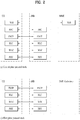
- FIG. 3 illustrates physical channels used in a 3GPP system and a general method for transmitting a signal using the physical channels.
- a user equipment performs initial cell search such as synchronizing with a base station when it newly enters a cell or the power is turned on (S301).
- the UE synchronizes with the base station by receiving a primary synchronization channel (P-SCH) and a secondary synchronization channel (S-SCH) from the base station, and acquires information such as cell ID, etc.
- the UE may acquire broadcast information within the cell by receiving a physical broadcast channel (PBCH) from the base station.
- PBCH physical broadcast channel
- the UE may identify a downlink channel status by receiving a downlink reference signal (DL RS) at the initial cell search step.
- DL RS downlink reference signal
- the UE which has finished the initial cell search may acquire more detailed system information by receiving a physical downlink shared channel (PDSCH) in accordance with a physical downlink control channel (PDCCH) and information carried in the PDCCH (S302).
- PDSCH physical downlink shared channel
- PDCCH physical downlink control channel
- the UE may perform a random access procedure (RACH) to complete access to the base station when the UE initially accesses the BS or has no radio resources for signal transmission (S303 to S306).
- RACH random access procedure
- the UE may transmit a specific sequence through a preamble over a physical random access channel (PRACH) (S303 and S305) and may receive a response message to the preamble through the PDCCH and the PDSCH corresponding to the PDCCH (S304 and S306).
- PRACH physical random access channel
- the UE may additionally perform a contention resolution procedure.
- the UE may be able to perform a PDCCH/PDSCH reception (S307) and a PUSCH/PUCCH (physical uplink shared channel/physical uplink control channel) transmission (S308) as a general uplink/downlink signal transmission procedure.
- DCI downlink control information
- DCI includes control information such as resource allocation information about the UE and has a format depending on purpose of use.
- Control information transmitted from the UE to the base station on uplink or transmitted from the base station to the UE includes a downlink/uplink ACK/NACK signal, a channel quality indicator (CQI), a precoding matrix index (PMI), a rank indicator (RI), etc.
- CQI channel quality indicator
- PMI precoding matrix index
- RI rank indicator
- the UE can transmit the control information such as CQI/PMI/RI through a PUSCH and/or a PUCCH.
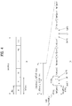
- FIG. 4 illustrates a structure of a radio frame used in LTE.
- transmission of an uplink/downlink data packet is performed on a subframe by subframe basis and one subframe is defined as a specific period including a plurality of OFDM symbols.
- 3GPP LTE standards support a type-1 radio frame structure applicable to FDD (Frequency Division Duplex) and a type-2 radio frame structure applicable to TDD (Time Division Duplex).
- FIG. 4(a) illustrates the type-1 radio frame structure.
- a downlink radio frame includes 10 subframes, each of which includes two slots in the time domain.
- a time taken to transmit one subframe is called a TTI (transmission time interval).
- one subframe may be 1 ms in length and one slot may be 0.5 ms in length.
- One slot includes a plurality of OFDM symbols in the time domain and a plurality of resource blocks (RBs) in the frequency domain.
- 3GPP LTE uses OFDMA on downlink and thus an OFDM symbol refers to one symbol period.
- An OFDM symbol may also be referred to as an SC-FDMA symbol or a symbol period.
- An RB as a resource allocation unit may include a plurality of consecutive subcarriers in one slot.
- the number of OFDM symbols included in one slot may depend on a CP (Cyclic Prefix) configuration.
- the CP includes an extended CP and a normal CP.
- the number of OFDM symbols included in one slot may be 7.
- the length of one OFDM symbol increases and thus the number of OFDM symbols included in one slot is less than that in the case of the normal CP.
- the number of OFDM symbols included in one slot can be 6.
- the extended CP can be used to reduce inter-symbol interference.
- one slot When the normal CP is used, one slot includes 7 OFDM symbols and thus one subframe includes 14 OFDM symbols.
- a maximum of three OFDM symbols located in a front portion of each subframe may be allocated to a PDCCH (Physical Downlink Control Channel) and the remaining symbols may be allocated to a PDSCH (Physical Downlink Shared Channel).
- PDCCH Physical Downlink Control Channel
- PDSCH Physical Downlink Shared Channel
- FIG. 4(b) illustrates the type-2 radio frame structure.
- the type-2 radio frame includes two half frames and each half frame is composed of four normal subframes each of which includes two slots and a special subframe including two slots, a DwPTS (Downlink Pilot Time Slot), a GP (Guard Period) and a UpPTS (Uplink Pilot Time Slot).
- DwPTS Downlink Pilot Time Slot
- GP Guard Period
- UpPTS Uplink Pilot Time Slot
- the DwPTS is used for initial cell search, synchronization or channel estimation in a UE.
- the UpPTS is used for channel estimation and uplink transmission synchronization of a UE in a BS. That is, the DwPTS is used for downlink transmission and the UpPTS is used for uplink transmission. Particularly, the UpPTS is used for transmission of a PRACH preamble or SRS.
- the GP is used to eliminate interference generated on uplink due to multipath delay of a downlink signal between uplink and downlink.
- Table 1 shows DwPTS and UpPTS when and the remaining period is set to a GP.
- Table 1 shows DwPTS and UpPTS when and the remaining period is set to a GP.
- Table 1 shows DwPTS and UpPTS when and the remaining period is set to a GP.
- Table 1 shows DwPTS and UpPTS when and the remaining period is set to a GP.
- Table 1 shows DwPTS and UpPTS when and the remaining period is set to a GP.
- Table 1 shows DwPTS and UpPTS when and the remaining period is set to a GP.
- the type-2 radio frame structure that is, an uplink/downlink (UL/DL) configuration in a TDD system is shown in Table 2.
- Table2 Uplink-downlink configuration
- Subframe number 0 1 2 3 4 5 6 7 8 9 0 5 ms D S U U U D S U U U 1 5 ms D S U U D D S U U D 2 5 ms D S U D D D S U D D 3 10 ms D S U U U D D D D D D 4 10 ms D S U U D D D D D D 5 10 ms D S U D D D D D D D D 6 5 ms D S U U U U D S U U U D S U U D
- D indicates a downlink subframe
- U indicates an uplink subframe
- S represents the special subframe.
- Table 2 shows downlink-to-uplink switching periodicity in a UL/DL subframe configuration in each system.
- the aforementioned radio frame structure is merely an example and the number of subframes included in a radio frame, the number of slots included in a subframe and the number of symbols included in a slot may be varied.
- New RAT currently considers a fixed Random Access CHannel (RACH) resource periodically appearing for an RACH transmission.
- a UE transmits RACH on the RACH resource.
- the RACH resource is separated into different resources respectively mapped to different downlink beams of a base station.
- the base station can receive a receiving (Rx) vector on each resource mapped to each downlink beam by precoding of forming the downlink beam of the base station.
- a UE can transmit information to the base station by performing a precoding with a receiving vector optimized for each downlink beam.
- each of the above-described separated resources is named an RACH beam resource. It is currently discussed that a UE transmits RACH on an RACH beam resource mapped to a downlink beam determined as optimal for the UE itself.
- the RACH beam resource determined as optimal by the UE shall be named a best RACH beam resource.
- RACH and ST may be used in a manner of sharing a resource by FDM.
- the SR resource may be separated into different resources respectively mapped to different downlink beams of a base station.
- the base station can receive an Rx vector on each resource mapped to each downlink beam by precoding of forming the downlink beam of the base station.
- a UE can transmit information to the base station by performing a precoding with an Rx vector optimized for each downlink beam.
- Each of the above-described separated resources is defined as a scheduling request beam resource.
- a UE transmits a scheduling request on an SR beam resource mapped to a downlink beam of a base station determined as optimal for the UE itself.
- the SR beam resource determined as optimal by the UE shall be named a best Scheduling Request (SR) beam resource.
- the scheduling request may basically consider the three kinds of cases, i.e., requests A to C as follows.
- a UE may have a best downlink beam recently confirmed by a base station. After the confirmation, a downlink beam different from the best downlink beam may be optimal.
- the scheduling request can be made on an SR beam resource mapped to a new best downlink beam according to a measurement result measured by the UE.
- the base station can directly give the UE the confirmation that a downlink beam is changed into a downlink beam desired by the UE. If so, unless a special situation, an operation of replacing a beam by a new downlink beam for the UE with a small delay is possible.
- a beam change when such a beam change is requested, in case that a UE makes a request for a beam change on the basis of a measurement result each time a best downlink beam is changed, if the UE moves on an inter-beam boundary line, a beam change may continue to occur between two beams alternately. This may bring a resource waste systematically. Or, while a beam change procedure continues, as a signal transmission is not performed in the course of the change, a delay speed (i.e., latency) may increase. To prevent this, when a UE makes a beam change request, if a measurement result is equal to or smaller than a most recently confirmed best downlink beam by a predetermined threshold, it is preferable that a beam change request is not allowed.
- the UE when a UE makes a request for replacement of a best downlink beam most recently confirmed by a base station, the UE can perform a transmission on an SR beam resource associated not with the best downlink beam most recently confirmed by the base station but with a downlink beam desiring a beam change on making a request (or a best downlink beam on making a request).
- the base station can directly confirm the beam change into a downlink beam desired by the UE without a separate feedback from the UE.
- the downlink transmission may be performed on the assumption of a best downlink beam most recently confirmed by the base station. After completion of the downlink transmission in progress or the downlink transmission scheduled to be performed, it can be confirmed that a current beam will be replaced by a beam desired by a UE. If this is further extended, it can be confirmed that a beam will be replaced after a predetermined time. And, such a predetermined time may be indicated on confirmation or defined in advance between transmission and reception.
- a base station may newly determine a downlink beam for a UE by receiving feedback of a beam relevant measurement result from the UE.
- a base station may newly determine a downlink beam for a UE by separately transmitting a beam relevant reference signal to the UE and then receiving feedback of a measurement result of the beam relevant reference signal separately transmitted to the UE.
- Such a measurement result may be regulated to be fed back only for a partially associated beam with reference to a beam currently desired to be changed by the UE.
- a UE desires the request B or the request C only, the UE can perform an operation based on the request B or the request C on an SR beam resource associated with a best downlink beam most recently confirmed by a base station. Yet, when the UE simultaneously desires an operation for the request A and an operation for the request B or simultaneously desires an operation based on the request A and an operation based on the request C, if the two operations are performed separately, it may be inefficient. Therefore, according to a second embodiment, when an operation based on the request A and an operation based on the request B are simultaneously desired or an operation based on the request A and an operation based on the request C are simultaneously desired, a method of operating it once is described.
- a UE while performing an operation for the request B or the request C, a UE can perform a transmission on an SR beam resource associated not with a best downlink beam most recently confirmed by a base station but with a downlink beam desiring a beam change on making a request (or a best downlink beam on making a request).
- the base station may be configured to determine that the UE desires the beam change. In this case, the base station can directly confirm that the beam change into a downlink beam desired by the UE will be performed without a separate feedback from the UE.
- the downlink transmission may be performed on the assumption of a best downlink beam most recently confirmed by the base station. Thereafter, the base station may confirm that a current beam will be replaced by a beam desired by a UE. If this is further extended, it can be confirmed that a beam will be replaced after a predetermined time. And, such a predetermined time may be indicated on confirmation or defined in advance between transmission and reception.
- a base station may newly determine a downlink beam for a UE by receiving feedback of a beam relevant measurement result from the UE.
- a base station may newly determine a downlink beam for a UE by separately transmitting a beam relevant reference signal to the UE and then receiving feedback of a measurement result of the signal from the UE.
- Such a measurement result may be regulated to be fed back only for a partially associated beam with reference to a beam currently desired to be changed by the UE.
- the UE when a UE desires to replace a best downlink beam most recently confirmed by a base station, the UE can perform a transmission not on a scheduling request resource associated with a downlink beam desired to be replaced but on a scheduling request resource associated with a best downlink beam confirmed by the base station. In doing so, information on the replacement desired downlink beam may be transmitted together with scheduling request information.
- the UE can transmit information not on the best downlink beam most recently confirmed by the base station but on a downlink beam desiring a beam change on making a request (or a best downlink beam on making a request) together with the request. Namely, if all beams are left as a set and indexes are transmitted, since an amount of the information may be large, the UE can transmit a value of a difference between an index of the best downlink beam most recently confirmed by the base station and an index of the downlink beam desiring the beam change on making the request (or the best downlink beam on making the request) together with the request.
- Such information on the beam change can distinguish that what kind of symbols are transmitted on transmitting the Scheduling Request (SR) with modulated symbols.
- SR Scheduling Request
- a reference signal may be sent together.
- information on a beam change may be mapped to a sequence of the SR.
- the base station can directly confirm that the beam change into a downlink beam desired by the UE will be performed without a separate feedback from the UE.
- the downlink transmission may be performed on the assumption of a best downlink beam most recently confirmed by the base station. Thereafter, it can be confirmed that a current beam will be replaced by a beam desired by a UE. If this is further extended, it can be confirmed that a beam will be replaced after a predetermined time. And, such a predetermined time may be indicated on confirmation or defined in advance between transmission and reception.
- a base station may newly determine a downlink beam for a UE by receiving feedback of a beam relevant measurement result from the UE.
- a base station may newly determine a downlink beam for a UE by separately transmitting a beam relevant reference signal to the UE and then receiving feedback of a measurement result of the signal from the UE.
- Such a measurement result may be regulated to be fed back only for a partially associated beam with reference to a beam currently desired to be changed by the UE.
- SR Scheduling Request
- a delay is generated in the course of an operation of a base station in response to a scheduling request.
- a UE uses an SR beam resource defined in common, when an SR beam resource appropriate for the UE appears, the UE makes a scheduling request, whereby a delay may be generated. To prevent such a delay, it is able to consider a method for a base station to allocate an SR beam resource UE-specifically.
- a base station does not configure an SR beam resource for all downlink beams for each UE but is able to configure an SR beam resource mapped to a partial beam neighboring to a downlink beam most recently confirmed for a UE by the base station.
- the partial beam may be defined as a beam index associated with a confirmed downlink beam. For example, when there are 3 indexes of a confirmed downlink beam, it is able to configure an SR beam resource for 5 downlink beams by making an SR beam resource associated with 4 neighboring downlink beam indexes.
- the total number of SR beam resources is defined as N
- a base station sets N or uses a pre-defined value
- a pattern form downlink beam indexes associated with a best downlink beam index most recently confirmed by the base station is defined and used.
- Such a value and pattern of N may be defined in advance or semi-statically configured for a UE through higher layer signaling such as RRC signaling.
- a base station may design a UE-specific SR beam resource not related to a beam.
- a UE On the UE-specific SR beam resource, a UE repeatedly transmits a Scheduling Request (SR) so as to enable the base station to check what is an optimal downlink beam for each of the repeated scheduling requests.
- SR Scheduling Request
- FIG. 5 illustrates a base station (BS) and a UE applicable to an embodiment of the present invention.
- a wireless communication system includes a relay
- communication is performed between a BS and the relay on a backhaul link and communication is performed between the relay and a UE on an access link.
- the BS or UE shown in the figure may be replaced by the relay as necessary.
- a wireless communication system includes a BS 110 and a UE 120.
- the BS 110 includes a processor 112, a memory 114 and a radio frequency (RF) unit 116.
- the processor 112 may be configured to implement the procedures and/or methods proposed by the present invention.
- the memory 114 is connected to the processor 112 and stores various types of information related to operations of the processor 112.
- the RF unit 116 is connected to the processor 112 and transmits and/or receives radio signals.
- the UE 120 includes a processor 122, a memory 124 and a radio frequency (RF) unit 126.
- the processor 122 may be configured to implement the procedures and/or methods proposed by the present invention.
- the memory 124 is connected to the processor 122 and stores various types of information related to operations of the processor 122.
- the RF unit 126 is connected to the processor 122 and transmits and/or receives radio signals.
- the BS 110 and/or the UE 120 may include a single antenna or multiple antennas.
- a specific operation described as performed by the BS may be performed by an upper node of the BS. Namely, it is apparent that, in a network comprised of a plurality of network nodes including a BS, various operations performed for communication with a UE may be performed by the BS, or network nodes other than the BS.
- the term BS may be replaced with the term, fixed station, Node B, eNode B (eNB), access point, etc.
- the embodiments of the present invention may be achieved by various means, for example, hardware, firmware, software, or a combination thereof.
- the methods according to the embodiments of the present invention may be achieved by one or more Application Specific Integrated Circuits (ASICs), Digital Signal Processors (DSPs), Digital Signal Processing Devices (DSPDs), Programmable Logic Devices (PLDs), Field Programmable Gate Arrays (FPGAs), processors, controllers, microcontrollers, microprocessors, etc.
- ASICs Application Specific Integrated Circuits
- DSPs Digital Signal Processors
- DSPDs Digital Signal Processing Devices
- PLDs Programmable Logic Devices
- FPGAs Field Programmable Gate Arrays
- processors controllers, microcontrollers, microprocessors, etc.
- the embodiments of the present invention may be implemented in the form of a module, a procedure, a function, etc.
- software code may be stored in a memory unit and executed by a processor.
- the memory unit may be located at the interior or exterior of the processor and may transmit data to and receive data from the processor via various known means.
- a method of transmitting a signal in a wireless communication system and apparatus therefor are applicable to various wireless communication systems.
Claims (9)
- Verfahren zur Signalübertragung durch ein Benutzergerät, UE, (120) in einem Drahtloskommunikationssystem, das Mehrfacheingang-Mehrfachausgang, MIMO, unterstützt, wobei das Verfahren aufweist:Übertragen einer Zeitplanungsaufforderung an eine Basisstation (110) auf einer ersten Zeitplanungsanforderungsstrahlressource von mehreren Zeitplanungsanforderungsstrahlressourcen, wobei die erste Zeitplanungsanforderungsressource auf einen von mehreren Downlink-Strahlen, die von der Basisstation (110) übertragen werden, abgebildet wird; undansprechend auf die Zeitplanungsanforderung von der Basisstation (110) Empfangen einer Bestätigungsnachricht,wobei die Bestätigungsnachricht eine Anzeige umfasst, die gemäß der ersten Zeitplanungsanforderungsstrahlressource und einem besten Downlink-Strahl, der im Voraus für das UE (120) konfiguriert wird, bestimmt wird,wobei die Anzeige, wenn die Zeitplanungsanforderung auf der ersten Zeitplanungsanforderungsstrahlressource gestellt wird, die auf einen neuen besten Downlink-Strahl abgebildet wird, der verschieden zu dem im Voraus für das UE konfigurierten Downlink-Strahl ist, anzeigt, dass der beste Downlink-Strahl in den neuen besten Downlink-Strahl, auf den die erste Zeitplanungsanforderungsstrahlressource abgebildet wird, geändert ist, undwobei die Änderung in den zweiten Downlink-Strahl derart geplant wird, dass sie nach einer vorgeschriebenen Zeit ausgeführt wird.
- Verfahren nach Anspruch 1, wobei die Zeitplanungsanforderung eine Anforderung einer Downlink-Strahländerung der Basisstation (110) und/oder eine Referenzsignalübertragungsanforderung zum Messen eines Downlink-Strahls der Basisstation (110) und/oder eine Ressourcenzuweisungsanforderung für die Datenübertragung aufweist.
- Verfahren nach Anspruch 1, wobei die Bestätigungsnachricht, wenn die Zeitplanungsanforderung ferner eine Referenzsignalanforderung aufweist, die unter Verwendung einer Zeitplanungsanforderungsstrahlressource, die auf einen neuen besten Downlink-Strahl abgebildet wird, der verschieden von dem im Voraus für das Benutzergerät konfigurierten besten Downlink-Strahl ist, an die Basisstation übertragen wird, ein Referenzsignal für den zweiten Downlink-Strahl anzeigt.
- Verfahren nach Anspruch 1, wobei die Bestätigungsnachricht, wenn die Zeitplanungsanforderung ferner eine Ressourcenzuweisungsanforderung für die Datenübertragung aufweist, die unter Verwendung einer Zeitplanungsanforderungsstrahlressource, die auf einen neuen besten Downlink-Strahl abgebildet wird, der verschieden von dem im Voraus für das Benutzergerät konfigurierten besten Downlink-Strahl ist, an die Basisstation übertragen wird, die Ressourcenzuweisung für die Datenübertragung anzeigt.
- Verfahren nach Anspruch 1, wobei die erste Zeitplanungsanforderungsstrahlressource zu dem besten Downlink-Strahl gehört, der im Voraus für das Benutzergerät konfiguriert wird, und die Zeitplanungsanforderung Indexinformationen für einen zweiten Downlink-Strahl umfasst.
- Verfahren nach Anspruch 5, wobei die Indexinformationen eine Indexdifferenz zwischen dem besten Downlink-Strahl und dem zweiten Downlink-Strahl umfassen.
- Verfahren nach Anspruch 1, wobei die erste Zeitplanungsanforderungsstrahlressource zu dem besten Downlink-Strahl und wenigstens einem zu dem besten Downlink-Strahl benachbarten Downlink-Strahl gehört.
- Verfahren nach Anspruch 7, wobei die Nummer des wenigstens einen Downlink-Strahls, der benachbart zu der Basisstation ist, durch die Basisstation angezeigt wird.
- Benutzergerät, UE, (120) in einem Drahtloskommunikationssystem, das Mehrfacheingang-Mehrfachausgang, MIMO, unterstützt, wobei das Benutzergerät (120) aufweist:eine Funkfrequenzeinheit (126); undeinen Prozessor (122), der konfiguriert ist, um eine Zeitplanungsanforderung an eine Basisstation (110) auf einer ersten Zeitplanungsanforderungsstrahlressource von mehreren Zeitplanungsanforderungsstrahlressourcen zu übertragen, wobei die erste Zeitplanungsanforderungsressource auf einen von mehreren Downlink-Strahlen, die von der Basisstation (110) übertragen werden, abgebildet wird, und ansprechend auf die Zeitplanungsanforderung von der Basisstation (110) eine Bestätigungsnachricht zu empfangen,wobei die Bestätigungsnachricht eine Anzeige umfasst, die gemäß der ersten Zeitplanungsanforderungsstrahlressource und einem besten Downlink-Strahl, der im Voraus für das UE (120) konfiguriert wird, bestimmt wird,wobei die Anzeige, wenn die Zeitplanungsanforderung auf der ersten Zeitplanungsanforderungsstrahlressource gestellt wird, die auf einen neuen besten Downlink-Strahl abgebildet wird, der verschieden zu dem im Voraus für das UE konfigurierten Downlink-Strahl ist, anzeigt, dass der beste Downlink-Strahl in den neuen besten Downlink-Strahl, auf den die erste Zeitplanungsanforderungsstrahlressource abgebildet wird, geändert ist, undwobei die Änderung in den zweiten Downlink-Strahl derart geplant wird, dass sie nach einer vorgeschriebenen Zeit ausgeführt wird.
Applications Claiming Priority (2)
| Application Number | Priority Date | Filing Date | Title |
|---|---|---|---|
| US201662373994P | 2016-08-12 | 2016-08-12 | |
| PCT/KR2017/008768 WO2018030851A1 (ko) | 2016-08-12 | 2017-08-11 | 무선 통신 시스템에서 신호 송신 방법 및 이를 위한 장치 |
Publications (3)
| Publication Number | Publication Date |
|---|---|
| EP3500036A1 EP3500036A1 (de) | 2019-06-19 |
| EP3500036A4 EP3500036A4 (de) | 2020-03-25 |
| EP3500036B1 true EP3500036B1 (de) | 2021-12-29 |
Family
ID=61163167
Family Applications (1)
| Application Number | Title | Priority Date | Filing Date |
|---|---|---|---|
| EP17839868.1A Active EP3500036B1 (de) | 2016-08-12 | 2017-08-11 | Signalübertragung in einem drahtloskommunikationssystem dafür |
Country Status (4)
| Country | Link |
|---|---|
| US (1) | US10779306B2 (de) |
| EP (1) | EP3500036B1 (de) |
| CN (1) | CN109479308B (de) |
| WO (1) | WO2018030851A1 (de) |
Families Citing this family (5)
| Publication number | Priority date | Publication date | Assignee | Title |
|---|---|---|---|---|
| US11109380B2 (en) * | 2018-04-05 | 2021-08-31 | Qualcomm Incorporated | Uplink control channel beam switch procedure |
| US11444680B2 (en) * | 2019-07-18 | 2022-09-13 | Qualcomm Incorporated | Beam switching in a high radio frequency spectrum band |
| CN113644951B (zh) * | 2020-05-11 | 2023-03-21 | 大唐移动通信设备有限公司 | 一种数据传输方法及设备 |
| CN113015257A (zh) * | 2021-02-08 | 2021-06-22 | 浙江香农通信科技有限公司 | 一种用于5g nr的调度请求处理方法及系统 |
| WO2023237177A1 (en) * | 2022-06-06 | 2023-12-14 | Telefonaktiebolaget Lm Ericsson (Publ) | Scheduling request sharing for hybrid beamforming |
Family Cites Families (16)
| Publication number | Priority date | Publication date | Assignee | Title |
|---|---|---|---|---|
| ATE511737T1 (de) | 2008-09-19 | 2011-06-15 | Alcatel Lucent | Verfahren zur satzbildung von mobilen stationen in mimo-systemen, entsprechende mobilstation, basisstation, betrieb und wartungszentrum und funkkommunikationsnetzwerk |
| KR101839386B1 (ko) * | 2011-08-12 | 2018-03-16 | 삼성전자주식회사 | 무선 통신 시스템에서의 적응적 빔포밍 장치 및 방법 |
| KR101828836B1 (ko) * | 2011-08-23 | 2018-02-13 | 삼성전자주식회사 | 빔 포밍 기반의 무선통신시스템에서 빔 스캐닝을 통한 스케줄링 장치 및 방법 |
| IN2014KN00830A (de) * | 2011-09-16 | 2015-10-02 | Samsung Electronics Co Ltd | |
| KR101995357B1 (ko) * | 2012-02-17 | 2019-07-02 | 삼성전자주식회사 | 빔포밍 기반 무선통신을 위한 제어 채널 운용 방법 및 장치 |
| KR101655924B1 (ko) * | 2012-03-07 | 2016-09-08 | 엘지전자 주식회사 | 무선 접속 시스템에서 계층적 빔 포밍 방법 및 이를 위한 장치 |
| US10292139B2 (en) * | 2012-06-29 | 2019-05-14 | Samsung Electronics Co., Ltd. | Method and apparatus for beamforming |
| KR101995798B1 (ko) * | 2012-07-03 | 2019-07-03 | 삼성전자주식회사 | 빔포밍을 사용하는 통신 시스템의 랜덤 억세스 장치 및 방법 |
| KR20140056561A (ko) * | 2012-10-29 | 2014-05-12 | 한국전자통신연구원 | 다중 빔을 운영하는 이동통신시스템에서 기지국 및 단말의 동작 방법 |
| JP5738338B2 (ja) * | 2013-03-29 | 2015-06-24 | 株式会社Nttドコモ | 無線通信システムおよび無線基地局装置 |
| CN104734759B (zh) | 2013-12-20 | 2019-12-03 | 中兴通讯股份有限公司 | Mimo波束赋形通信系统中波束识别方法、相关设备及系统 |
| US20190104549A1 (en) * | 2014-11-26 | 2019-04-04 | Idac Holdings, Inc. | Initial access in high frequency wireless systems |
| US9913290B2 (en) * | 2015-01-26 | 2018-03-06 | Asustek Computer Inc. | Method and apparatus for handling uplink transmission in a wireless communication system |
| US10341959B2 (en) * | 2016-04-28 | 2019-07-02 | Qualcomm Incorporated | Uplink transmit power control after beam change |
| WO2017221202A1 (en) * | 2016-06-23 | 2017-12-28 | Nokia Technologies Oy | Beam change |
| CN107548119B (zh) * | 2016-06-24 | 2020-10-23 | 华硕电脑股份有限公司 | 用于无线通信系统中执行用户设备波束成形的方法和设备 |
-
2017
- 2017-08-11 CN CN201780043207.9A patent/CN109479308B/zh active Active
- 2017-08-11 US US16/324,821 patent/US10779306B2/en active Active
- 2017-08-11 EP EP17839868.1A patent/EP3500036B1/de active Active
- 2017-08-11 WO PCT/KR2017/008768 patent/WO2018030851A1/ko unknown
Also Published As
| Publication number | Publication date |
|---|---|
| CN109479308A (zh) | 2019-03-15 |
| US10779306B2 (en) | 2020-09-15 |
| US20190230680A1 (en) | 2019-07-25 |
| WO2018030851A1 (ko) | 2018-02-15 |
| EP3500036A4 (de) | 2020-03-25 |
| CN109479308B (zh) | 2022-01-14 |
| EP3500036A1 (de) | 2019-06-19 |
Similar Documents
| Publication | Publication Date | Title |
|---|---|---|
| EP2943002B1 (de) | Verfahren zur überwachung von downlink-steuerkanälen in einem drahtlosen kommunikationssystem und vorrichtung dafür | |
| US9705644B2 (en) | Method for operating buffer for device-to-device (D2D) communication in wireless communication system, and apparatus for same | |
| US10149256B2 (en) | Method for controlling power for device-to-device (D2D) communication in wireless communication system and apparatus for same | |
| EP3128686A1 (de) | Verfahren zur konfigurierung von interferenzmessungsressourcen in einem drahtloskommunikationssystem und vorrichtung dafür | |
| EP3500036B1 (de) | Signalübertragung in einem drahtloskommunikationssystem dafür | |
| US9461779B2 (en) | Method for transmitting uplink data information in a wireless communication system and apparatus therefor | |
| US11178626B2 (en) | Method for transmitting synchronization signal and device therefor | |
| US11296836B2 (en) | Method for transmitting and receiving signal based on LTE and NR in wireless communication system and apparatus therefor | |
| US10154499B2 (en) | Method for sharing wireless resource information in multi-cell wireless communication system and apparatus for same | |
| EP3694284B1 (de) | Verfahren und vorrichtung für signalübertragung oder -empfang auf der basis von lte und nr in einem drahtlosen kommunikationssystem | |
| JP2017521880A (ja) | 無線通信システムで端末間の通信のための信号を送受信する方法及び装置 | |
| EP3471325B1 (de) | Dm-rs-übertragungsverfahren für rundfunkdaten in einem kommunikationssystem der nächsten generation und vorrichtung dafür | |
| US20200169998A1 (en) | Method for transmitting/receiving signal on basis of lte and nr in wireless communication system, and device therefor | |
| EP3128800B1 (de) | Verfahren zum übertragen und empfangen eines signals für d2d-kommunikation in einem drahtloskommunikationssystem und vorrichtung dafür | |
| US11258486B2 (en) | Method for transmitting signal in wireless communication system and apparatus for same | |
| US9264210B2 (en) | Method for user equipment transreceiving signal in wireless communication system | |
| EP3139522B1 (de) | Verfahren zum empfangen von signalen zwischen zwei vorrichtungen in einem drahtloskommunikationssystem mit trägeraggregationsunterstützung und vorrichtung dafür | |
| US11177925B2 (en) | Method for setting frame structure in wireless communication system and device therefor |
Legal Events
| Date | Code | Title | Description |
|---|---|---|---|
| STAA | Information on the status of an ep patent application or granted ep patent |
Free format text: STATUS: THE INTERNATIONAL PUBLICATION HAS BEEN MADE |
|
| PUAI | Public reference made under article 153(3) epc to a published international application that has entered the european phase |
Free format text: ORIGINAL CODE: 0009012 |
|
| STAA | Information on the status of an ep patent application or granted ep patent |
Free format text: STATUS: REQUEST FOR EXAMINATION WAS MADE |
|
| 17P | Request for examination filed |
Effective date: 20190213 |
|
| AK | Designated contracting states |
Kind code of ref document: A1 Designated state(s): AL AT BE BG CH CY CZ DE DK EE ES FI FR GB GR HR HU IE IS IT LI LT LU LV MC MK MT NL NO PL PT RO RS SE SI SK SM TR |
|
| AX | Request for extension of the european patent |
Extension state: BA ME |
|
| DAV | Request for validation of the european patent (deleted) | ||
| DAX | Request for extension of the european patent (deleted) | ||
| A4 | Supplementary search report drawn up and despatched |
Effective date: 20200221 |
|
| RIC1 | Information provided on ipc code assigned before grant |
Ipc: H04W 72/12 20090101AFI20200217BHEP Ipc: H04W 72/04 20090101ALI20200217BHEP Ipc: H04B 7/0413 20170101ALI20200217BHEP |
|
| REG | Reference to a national code |
Ref country code: DE Ref legal event code: R079 Ref document number: 602017051676 Country of ref document: DE Free format text: PREVIOUS MAIN CLASS: H04W0072120000 Ipc: H04B0007060000 |
|
| RIC1 | Information provided on ipc code assigned before grant |
Ipc: H04W 72/12 20090101ALI20210201BHEP Ipc: H04B 7/06 20060101AFI20210201BHEP Ipc: H04W 72/04 20090101ALI20210201BHEP |
|
| GRAP | Despatch of communication of intention to grant a patent |
Free format text: ORIGINAL CODE: EPIDOSNIGR1 |
|
| STAA | Information on the status of an ep patent application or granted ep patent |
Free format text: STATUS: GRANT OF PATENT IS INTENDED |
|
| INTG | Intention to grant announced |
Effective date: 20210312 |
|
| GRAJ | Information related to disapproval of communication of intention to grant by the applicant or resumption of examination proceedings by the epo deleted |
Free format text: ORIGINAL CODE: EPIDOSDIGR1 |
|
| STAA | Information on the status of an ep patent application or granted ep patent |
Free format text: STATUS: REQUEST FOR EXAMINATION WAS MADE |
|
| GRAP | Despatch of communication of intention to grant a patent |
Free format text: ORIGINAL CODE: EPIDOSNIGR1 |
|
| STAA | Information on the status of an ep patent application or granted ep patent |
Free format text: STATUS: GRANT OF PATENT IS INTENDED |
|
| INTC | Intention to grant announced (deleted) | ||
| INTG | Intention to grant announced |
Effective date: 20210809 |
|
| GRAS | Grant fee paid |
Free format text: ORIGINAL CODE: EPIDOSNIGR3 |
|
| GRAA | (expected) grant |
Free format text: ORIGINAL CODE: 0009210 |
|
| STAA | Information on the status of an ep patent application or granted ep patent |
Free format text: STATUS: THE PATENT HAS BEEN GRANTED |
|
| AK | Designated contracting states |
Kind code of ref document: B1 Designated state(s): AL AT BE BG CH CY CZ DE DK EE ES FI FR GB GR HR HU IE IS IT LI LT LU LV MC MK MT NL NO PL PT RO RS SE SI SK SM TR |
|
| REG | Reference to a national code |
Ref country code: GB Ref legal event code: FG4D |
|
| REG | Reference to a national code |
Ref country code: CH Ref legal event code: EP |
|
| REG | Reference to a national code |
Ref country code: AT Ref legal event code: REF Ref document number: 1459453 Country of ref document: AT Kind code of ref document: T Effective date: 20220115 |
|
| REG | Reference to a national code |
Ref country code: IE Ref legal event code: FG4D |
|
| REG | Reference to a national code |
Ref country code: DE Ref legal event code: R096 Ref document number: 602017051676 Country of ref document: DE |
|
| REG | Reference to a national code |
Ref country code: LT Ref legal event code: MG9D |
|
| PG25 | Lapsed in a contracting state [announced via postgrant information from national office to epo] |
Ref country code: RS Free format text: LAPSE BECAUSE OF FAILURE TO SUBMIT A TRANSLATION OF THE DESCRIPTION OR TO PAY THE FEE WITHIN THE PRESCRIBED TIME-LIMIT Effective date: 20211229 Ref country code: LT Free format text: LAPSE BECAUSE OF FAILURE TO SUBMIT A TRANSLATION OF THE DESCRIPTION OR TO PAY THE FEE WITHIN THE PRESCRIBED TIME-LIMIT Effective date: 20211229 Ref country code: FI Free format text: LAPSE BECAUSE OF FAILURE TO SUBMIT A TRANSLATION OF THE DESCRIPTION OR TO PAY THE FEE WITHIN THE PRESCRIBED TIME-LIMIT Effective date: 20211229 Ref country code: BG Free format text: LAPSE BECAUSE OF FAILURE TO SUBMIT A TRANSLATION OF THE DESCRIPTION OR TO PAY THE FEE WITHIN THE PRESCRIBED TIME-LIMIT Effective date: 20220329 |
|
| REG | Reference to a national code |
Ref country code: NL Ref legal event code: MP Effective date: 20211229 |
|
| REG | Reference to a national code |
Ref country code: AT Ref legal event code: MK05 Ref document number: 1459453 Country of ref document: AT Kind code of ref document: T Effective date: 20211229 |
|
| PG25 | Lapsed in a contracting state [announced via postgrant information from national office to epo] |
Ref country code: SE Free format text: LAPSE BECAUSE OF FAILURE TO SUBMIT A TRANSLATION OF THE DESCRIPTION OR TO PAY THE FEE WITHIN THE PRESCRIBED TIME-LIMIT Effective date: 20211229 Ref country code: NO Free format text: LAPSE BECAUSE OF FAILURE TO SUBMIT A TRANSLATION OF THE DESCRIPTION OR TO PAY THE FEE WITHIN THE PRESCRIBED TIME-LIMIT Effective date: 20220329 Ref country code: LV Free format text: LAPSE BECAUSE OF FAILURE TO SUBMIT A TRANSLATION OF THE DESCRIPTION OR TO PAY THE FEE WITHIN THE PRESCRIBED TIME-LIMIT Effective date: 20211229 Ref country code: HR Free format text: LAPSE BECAUSE OF FAILURE TO SUBMIT A TRANSLATION OF THE DESCRIPTION OR TO PAY THE FEE WITHIN THE PRESCRIBED TIME-LIMIT Effective date: 20211229 Ref country code: GR Free format text: LAPSE BECAUSE OF FAILURE TO SUBMIT A TRANSLATION OF THE DESCRIPTION OR TO PAY THE FEE WITHIN THE PRESCRIBED TIME-LIMIT Effective date: 20220330 |
|
| PG25 | Lapsed in a contracting state [announced via postgrant information from national office to epo] |
Ref country code: NL Free format text: LAPSE BECAUSE OF FAILURE TO SUBMIT A TRANSLATION OF THE DESCRIPTION OR TO PAY THE FEE WITHIN THE PRESCRIBED TIME-LIMIT Effective date: 20211229 |
|
| PG25 | Lapsed in a contracting state [announced via postgrant information from national office to epo] |
Ref country code: SM Free format text: LAPSE BECAUSE OF FAILURE TO SUBMIT A TRANSLATION OF THE DESCRIPTION OR TO PAY THE FEE WITHIN THE PRESCRIBED TIME-LIMIT Effective date: 20211229 Ref country code: SK Free format text: LAPSE BECAUSE OF FAILURE TO SUBMIT A TRANSLATION OF THE DESCRIPTION OR TO PAY THE FEE WITHIN THE PRESCRIBED TIME-LIMIT Effective date: 20211229 Ref country code: RO Free format text: LAPSE BECAUSE OF FAILURE TO SUBMIT A TRANSLATION OF THE DESCRIPTION OR TO PAY THE FEE WITHIN THE PRESCRIBED TIME-LIMIT Effective date: 20211229 Ref country code: PT Free format text: LAPSE BECAUSE OF FAILURE TO SUBMIT A TRANSLATION OF THE DESCRIPTION OR TO PAY THE FEE WITHIN THE PRESCRIBED TIME-LIMIT Effective date: 20220429 Ref country code: ES Free format text: LAPSE BECAUSE OF FAILURE TO SUBMIT A TRANSLATION OF THE DESCRIPTION OR TO PAY THE FEE WITHIN THE PRESCRIBED TIME-LIMIT Effective date: 20211229 Ref country code: EE Free format text: LAPSE BECAUSE OF FAILURE TO SUBMIT A TRANSLATION OF THE DESCRIPTION OR TO PAY THE FEE WITHIN THE PRESCRIBED TIME-LIMIT Effective date: 20211229 Ref country code: CZ Free format text: LAPSE BECAUSE OF FAILURE TO SUBMIT A TRANSLATION OF THE DESCRIPTION OR TO PAY THE FEE WITHIN THE PRESCRIBED TIME-LIMIT Effective date: 20211229 |
|
| PG25 | Lapsed in a contracting state [announced via postgrant information from national office to epo] |
Ref country code: PL Free format text: LAPSE BECAUSE OF FAILURE TO SUBMIT A TRANSLATION OF THE DESCRIPTION OR TO PAY THE FEE WITHIN THE PRESCRIBED TIME-LIMIT Effective date: 20211229 Ref country code: AT Free format text: LAPSE BECAUSE OF FAILURE TO SUBMIT A TRANSLATION OF THE DESCRIPTION OR TO PAY THE FEE WITHIN THE PRESCRIBED TIME-LIMIT Effective date: 20211229 |
|
| PG25 | Lapsed in a contracting state [announced via postgrant information from national office to epo] |
Ref country code: IS Free format text: LAPSE BECAUSE OF FAILURE TO SUBMIT A TRANSLATION OF THE DESCRIPTION OR TO PAY THE FEE WITHIN THE PRESCRIBED TIME-LIMIT Effective date: 20220429 |
|
| REG | Reference to a national code |
Ref country code: DE Ref legal event code: R097 Ref document number: 602017051676 Country of ref document: DE |
|
| PG25 | Lapsed in a contracting state [announced via postgrant information from national office to epo] |
Ref country code: DK Free format text: LAPSE BECAUSE OF FAILURE TO SUBMIT A TRANSLATION OF THE DESCRIPTION OR TO PAY THE FEE WITHIN THE PRESCRIBED TIME-LIMIT Effective date: 20211229 Ref country code: AL Free format text: LAPSE BECAUSE OF FAILURE TO SUBMIT A TRANSLATION OF THE DESCRIPTION OR TO PAY THE FEE WITHIN THE PRESCRIBED TIME-LIMIT Effective date: 20211229 |
|
| PLBE | No opposition filed within time limit |
Free format text: ORIGINAL CODE: 0009261 |
|
| STAA | Information on the status of an ep patent application or granted ep patent |
Free format text: STATUS: NO OPPOSITION FILED WITHIN TIME LIMIT |
|
| 26N | No opposition filed |
Effective date: 20220930 |
|
| PG25 | Lapsed in a contracting state [announced via postgrant information from national office to epo] |
Ref country code: SI Free format text: LAPSE BECAUSE OF FAILURE TO SUBMIT A TRANSLATION OF THE DESCRIPTION OR TO PAY THE FEE WITHIN THE PRESCRIBED TIME-LIMIT Effective date: 20211229 |
|
| PG25 | Lapsed in a contracting state [announced via postgrant information from national office to epo] |
Ref country code: MC Free format text: LAPSE BECAUSE OF FAILURE TO SUBMIT A TRANSLATION OF THE DESCRIPTION OR TO PAY THE FEE WITHIN THE PRESCRIBED TIME-LIMIT Effective date: 20211229 |
|
| REG | Reference to a national code |
Ref country code: CH Ref legal event code: PL |
|
| GBPC | Gb: european patent ceased through non-payment of renewal fee |
Effective date: 20220811 |
|
| PG25 | Lapsed in a contracting state [announced via postgrant information from national office to epo] |
Ref country code: LU Free format text: LAPSE BECAUSE OF NON-PAYMENT OF DUE FEES Effective date: 20220811 Ref country code: LI Free format text: LAPSE BECAUSE OF NON-PAYMENT OF DUE FEES Effective date: 20220831 Ref country code: CH Free format text: LAPSE BECAUSE OF NON-PAYMENT OF DUE FEES Effective date: 20220831 |
|
| REG | Reference to a national code |
Ref country code: BE Ref legal event code: MM Effective date: 20220831 |
|
| PG25 | Lapsed in a contracting state [announced via postgrant information from national office to epo] |
Ref country code: IT Free format text: LAPSE BECAUSE OF FAILURE TO SUBMIT A TRANSLATION OF THE DESCRIPTION OR TO PAY THE FEE WITHIN THE PRESCRIBED TIME-LIMIT Effective date: 20211229 |
|
| PG25 | Lapsed in a contracting state [announced via postgrant information from national office to epo] |
Ref country code: IE Free format text: LAPSE BECAUSE OF NON-PAYMENT OF DUE FEES Effective date: 20220811 Ref country code: FR Free format text: LAPSE BECAUSE OF NON-PAYMENT OF DUE FEES Effective date: 20220831 |
|
| PG25 | Lapsed in a contracting state [announced via postgrant information from national office to epo] |
Ref country code: BE Free format text: LAPSE BECAUSE OF NON-PAYMENT OF DUE FEES Effective date: 20220831 |
|
| PG25 | Lapsed in a contracting state [announced via postgrant information from national office to epo] |
Ref country code: GB Free format text: LAPSE BECAUSE OF NON-PAYMENT OF DUE FEES Effective date: 20220811 |
|
| PGFP | Annual fee paid to national office [announced via postgrant information from national office to epo] |
Ref country code: DE Payment date: 20230705 Year of fee payment: 7 |
|
| PG25 | Lapsed in a contracting state [announced via postgrant information from national office to epo] |
Ref country code: HU Free format text: LAPSE BECAUSE OF FAILURE TO SUBMIT A TRANSLATION OF THE DESCRIPTION OR TO PAY THE FEE WITHIN THE PRESCRIBED TIME-LIMIT; INVALID AB INITIO Effective date: 20170811 |
|
| PG25 | Lapsed in a contracting state [announced via postgrant information from national office to epo] |
Ref country code: CY Free format text: LAPSE BECAUSE OF FAILURE TO SUBMIT A TRANSLATION OF THE DESCRIPTION OR TO PAY THE FEE WITHIN THE PRESCRIBED TIME-LIMIT Effective date: 20211229 |