EP3499621A1 - Fuel cell device - Google Patents
Fuel cell device Download PDFInfo
- Publication number
- EP3499621A1 EP3499621A1 EP17839526.5A EP17839526A EP3499621A1 EP 3499621 A1 EP3499621 A1 EP 3499621A1 EP 17839526 A EP17839526 A EP 17839526A EP 3499621 A1 EP3499621 A1 EP 3499621A1
- Authority
- EP
- European Patent Office
- Prior art keywords
- fuel cell
- air
- duct
- heat
- opening
- Prior art date
- Legal status (The legal status is an assumption and is not a legal conclusion. Google has not performed a legal analysis and makes no representation as to the accuracy of the status listed.)
- Granted
Links
Images






Classifications
-
- H—ELECTRICITY
- H01—ELECTRIC ELEMENTS
- H01M—PROCESSES OR MEANS, e.g. BATTERIES, FOR THE DIRECT CONVERSION OF CHEMICAL ENERGY INTO ELECTRICAL ENERGY
- H01M8/00—Fuel cells; Manufacture thereof
- H01M8/04—Auxiliary arrangements, e.g. for control of pressure or for circulation of fluids
- H01M8/04298—Processes for controlling fuel cells or fuel cell systems
- H01M8/04694—Processes for controlling fuel cells or fuel cell systems characterised by variables to be controlled
- H01M8/04701—Temperature
- H01M8/04723—Temperature of the coolant
-
- H—ELECTRICITY
- H01—ELECTRIC ELEMENTS
- H01M—PROCESSES OR MEANS, e.g. BATTERIES, FOR THE DIRECT CONVERSION OF CHEMICAL ENERGY INTO ELECTRICAL ENERGY
- H01M8/00—Fuel cells; Manufacture thereof
- H01M8/04—Auxiliary arrangements, e.g. for control of pressure or for circulation of fluids
- H01M8/04298—Processes for controlling fuel cells or fuel cell systems
- H01M8/04694—Processes for controlling fuel cells or fuel cell systems characterised by variables to be controlled
- H01M8/04701—Temperature
-
- F—MECHANICAL ENGINEERING; LIGHTING; HEATING; WEAPONS; BLASTING
- F28—HEAT EXCHANGE IN GENERAL
- F28D—HEAT-EXCHANGE APPARATUS, NOT PROVIDED FOR IN ANOTHER SUBCLASS, IN WHICH THE HEAT-EXCHANGE MEDIA DO NOT COME INTO DIRECT CONTACT
- F28D1/00—Heat-exchange apparatus having stationary conduit assemblies for one heat-exchange medium only, the media being in contact with different sides of the conduit wall, in which the other heat-exchange medium is a large body of fluid, e.g. domestic or motor car radiators
- F28D1/02—Heat-exchange apparatus having stationary conduit assemblies for one heat-exchange medium only, the media being in contact with different sides of the conduit wall, in which the other heat-exchange medium is a large body of fluid, e.g. domestic or motor car radiators with heat-exchange conduits immersed in the body of fluid
- F28D1/0233—Heat-exchange apparatus having stationary conduit assemblies for one heat-exchange medium only, the media being in contact with different sides of the conduit wall, in which the other heat-exchange medium is a large body of fluid, e.g. domestic or motor car radiators with heat-exchange conduits immersed in the body of fluid with air flow channels
- F28D1/024—Heat-exchange apparatus having stationary conduit assemblies for one heat-exchange medium only, the media being in contact with different sides of the conduit wall, in which the other heat-exchange medium is a large body of fluid, e.g. domestic or motor car radiators with heat-exchange conduits immersed in the body of fluid with air flow channels with an air driving element
-
- H—ELECTRICITY
- H01—ELECTRIC ELEMENTS
- H01M—PROCESSES OR MEANS, e.g. BATTERIES, FOR THE DIRECT CONVERSION OF CHEMICAL ENERGY INTO ELECTRICAL ENERGY
- H01M8/00—Fuel cells; Manufacture thereof
- H01M8/04—Auxiliary arrangements, e.g. for control of pressure or for circulation of fluids
-
- H—ELECTRICITY
- H01—ELECTRIC ELEMENTS
- H01M—PROCESSES OR MEANS, e.g. BATTERIES, FOR THE DIRECT CONVERSION OF CHEMICAL ENERGY INTO ELECTRICAL ENERGY
- H01M8/00—Fuel cells; Manufacture thereof
- H01M8/04—Auxiliary arrangements, e.g. for control of pressure or for circulation of fluids
- H01M8/04007—Auxiliary arrangements, e.g. for control of pressure or for circulation of fluids related to heat exchange
-
- H—ELECTRICITY
- H01—ELECTRIC ELEMENTS
- H01M—PROCESSES OR MEANS, e.g. BATTERIES, FOR THE DIRECT CONVERSION OF CHEMICAL ENERGY INTO ELECTRICAL ENERGY
- H01M8/00—Fuel cells; Manufacture thereof
- H01M8/04—Auxiliary arrangements, e.g. for control of pressure or for circulation of fluids
- H01M8/04007—Auxiliary arrangements, e.g. for control of pressure or for circulation of fluids related to heat exchange
- H01M8/04014—Heat exchange using gaseous fluids; Heat exchange by combustion of reactants
-
- H—ELECTRICITY
- H01—ELECTRIC ELEMENTS
- H01M—PROCESSES OR MEANS, e.g. BATTERIES, FOR THE DIRECT CONVERSION OF CHEMICAL ENERGY INTO ELECTRICAL ENERGY
- H01M8/00—Fuel cells; Manufacture thereof
- H01M8/04—Auxiliary arrangements, e.g. for control of pressure or for circulation of fluids
- H01M8/04007—Auxiliary arrangements, e.g. for control of pressure or for circulation of fluids related to heat exchange
- H01M8/04014—Heat exchange using gaseous fluids; Heat exchange by combustion of reactants
- H01M8/04022—Heating by combustion
-
- H—ELECTRICITY
- H01—ELECTRIC ELEMENTS
- H01M—PROCESSES OR MEANS, e.g. BATTERIES, FOR THE DIRECT CONVERSION OF CHEMICAL ENERGY INTO ELECTRICAL ENERGY
- H01M8/00—Fuel cells; Manufacture thereof
- H01M8/04—Auxiliary arrangements, e.g. for control of pressure or for circulation of fluids
- H01M8/04007—Auxiliary arrangements, e.g. for control of pressure or for circulation of fluids related to heat exchange
- H01M8/04029—Heat exchange using liquids
-
- H—ELECTRICITY
- H01—ELECTRIC ELEMENTS
- H01M—PROCESSES OR MEANS, e.g. BATTERIES, FOR THE DIRECT CONVERSION OF CHEMICAL ENERGY INTO ELECTRICAL ENERGY
- H01M8/00—Fuel cells; Manufacture thereof
- H01M8/04—Auxiliary arrangements, e.g. for control of pressure or for circulation of fluids
- H01M8/04007—Auxiliary arrangements, e.g. for control of pressure or for circulation of fluids related to heat exchange
- H01M8/04067—Heat exchange or temperature measuring elements, thermal insulation, e.g. heat pipes, heat pumps, fins
-
- H—ELECTRICITY
- H01—ELECTRIC ELEMENTS
- H01M—PROCESSES OR MEANS, e.g. BATTERIES, FOR THE DIRECT CONVERSION OF CHEMICAL ENERGY INTO ELECTRICAL ENERGY
- H01M8/00—Fuel cells; Manufacture thereof
- H01M8/04—Auxiliary arrangements, e.g. for control of pressure or for circulation of fluids
- H01M8/04007—Auxiliary arrangements, e.g. for control of pressure or for circulation of fluids related to heat exchange
- H01M8/04067—Heat exchange or temperature measuring elements, thermal insulation, e.g. heat pipes, heat pumps, fins
- H01M8/04074—Heat exchange unit structures specially adapted for fuel cell
-
- H—ELECTRICITY
- H01—ELECTRIC ELEMENTS
- H01M—PROCESSES OR MEANS, e.g. BATTERIES, FOR THE DIRECT CONVERSION OF CHEMICAL ENERGY INTO ELECTRICAL ENERGY
- H01M8/00—Fuel cells; Manufacture thereof
- H01M8/04—Auxiliary arrangements, e.g. for control of pressure or for circulation of fluids
- H01M8/04298—Processes for controlling fuel cells or fuel cell systems
- H01M8/04694—Processes for controlling fuel cells or fuel cell systems characterised by variables to be controlled
- H01M8/04701—Temperature
- H01M8/04716—Temperature of fuel cell exhausts
-
- H—ELECTRICITY
- H01—ELECTRIC ELEMENTS
- H01M—PROCESSES OR MEANS, e.g. BATTERIES, FOR THE DIRECT CONVERSION OF CHEMICAL ENERGY INTO ELECTRICAL ENERGY
- H01M8/00—Fuel cells; Manufacture thereof
- H01M8/04—Auxiliary arrangements, e.g. for control of pressure or for circulation of fluids
- H01M8/04298—Processes for controlling fuel cells or fuel cell systems
- H01M8/04694—Processes for controlling fuel cells or fuel cell systems characterised by variables to be controlled
- H01M8/04746—Pressure; Flow
-
- F—MECHANICAL ENGINEERING; LIGHTING; HEATING; WEAPONS; BLASTING
- F28—HEAT EXCHANGE IN GENERAL
- F28D—HEAT-EXCHANGE APPARATUS, NOT PROVIDED FOR IN ANOTHER SUBCLASS, IN WHICH THE HEAT-EXCHANGE MEDIA DO NOT COME INTO DIRECT CONTACT
- F28D21/00—Heat-exchange apparatus not covered by any of the groups F28D1/00 - F28D20/00
- F28D2021/0019—Other heat exchangers for particular applications; Heat exchange systems not otherwise provided for
- F28D2021/0043—Other heat exchangers for particular applications; Heat exchange systems not otherwise provided for for fuel cells
-
- Y—GENERAL TAGGING OF NEW TECHNOLOGICAL DEVELOPMENTS; GENERAL TAGGING OF CROSS-SECTIONAL TECHNOLOGIES SPANNING OVER SEVERAL SECTIONS OF THE IPC; TECHNICAL SUBJECTS COVERED BY FORMER USPC CROSS-REFERENCE ART COLLECTIONS [XRACs] AND DIGESTS
- Y02—TECHNOLOGIES OR APPLICATIONS FOR MITIGATION OR ADAPTATION AGAINST CLIMATE CHANGE
- Y02E—REDUCTION OF GREENHOUSE GAS [GHG] EMISSIONS, RELATED TO ENERGY GENERATION, TRANSMISSION OR DISTRIBUTION
- Y02E60/00—Enabling technologies; Technologies with a potential or indirect contribution to GHG emissions mitigation
- Y02E60/30—Hydrogen technology
- Y02E60/50—Fuel cells
Definitions
- the present invention relates to a fuel cell apparatus.
- next-generation energy sources there have been proposed various fuel cell modules of the type including a cell stack, which is housed in a housing, including a plurality of stacked fuel cells capable of obtaining electric power by utilizing a fuel gas (hydrogen-containing gas) and air (oxygen-containing gas), and also fuel cell apparatuses each including such a fuel cell module housed in an exterior case.
- a fuel gas hydrogen-containing gas
- air oxygen-containing gas
- a fuel cell apparatus including a heat storage tank, in which a heat exchanger carries out heat exchange between exhaust gas from a fuel cell module and a medium such as water to cool the exhaust gas for recovery and reuse of water contained in the exhaust gas, and also the heat recovered by the medium is utilized for the supply of hot water.
- a heat exchanger carries out heat exchange between exhaust gas from a fuel cell module and a medium such as water to cool the exhaust gas for recovery and reuse of water contained in the exhaust gas, and also the heat recovered by the medium is utilized for the supply of hot water.
- Patent Literature 1 discloses a construction in which an exterior case has an air inlet provided in one surface thereof and an air outlet provided in the opposite surface thereof
- Patent Literature 2 discloses a construction in which an exterior case has an air inlet and an air outlet for a heat dissipator provided in one and the same surface thereof.
- Patent Literatures 3 and 4 disclose a fuel cell apparatus having an air flow channel such as a duct.
- a fuel cell apparatus comprises: a fuel cell module; a heat exchanger which carries out heat exchange between exhaust gas from the fuel cell module and a medium; a circulation line connected to the heat exchanger, the circulation line allowing the medium to circulate the heat exchanger; a heat dissipator located in the circulation line, the heat dissipator cooling the medium flowing through the heat exchanger; and an exterior case which houses the fuel cell module, the heat exchanger, the heat dissipator, and at least part of the circulation line.
- the heat dissipator is provided with two openings.
- the heat dissipator includes at least a duct which defines an air flow channel between the two openings; a fan located closer to one opening of the two openings than the other opening in the air flow channel, the fan producing flowing air; and a radiator located closer to the other opening of the two openings than the one opening in the air flow channel, the radiator carrying out heat exchange between the medium and air flowing through an interior of the air flow channel.
- the exterior case is provided with two ventilation holes to which the two openings are connected directly or via an air passageway, respectively, and the duct comprises a plurality of separable parts.
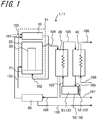
- FIG. 1 is a block diagram showing the structure of an example of a fuel cell apparatus according to the present disclosure.
- a fuel cell apparatus 1 according to the first embodiment includes a reformer 10, a cell stack device 20, a heat exchanger 30, a heat-storage tank 40, a heat dissipator 50, and a condensed water tank 60.
- Each such constituent device is, together with auxiliary machines which operate a fuel cell module 91 as described later, housed in an exterior case, not shown.
- the heat-storage tank 40 and the heat exchanger 30 may be disposed outside the exterior case.
- the fuel cell apparatus in which apart of the aforenamed devices is omitted is also possible.
- a raw fuel supply pipe 100 which supplies a raw fuel and a water supply pipe 101 which supplies reformed water are connected to the reformer 10. Inside the heated reformer 10, the raw fuel and the reformed water undergo reforming reactions with each other to produce a hydrogen-containing reformed gas.
- the reformed gas produced in the reformer 10 is supplied to the cell stack device 20 through a reformed gas supply pipe 102.
- the cell stack device 20 includes a manifold 21 and a cell stack 22.
- the reformed gas supplied to the cell stack device 20 is supplied from the manifold 21 into the cell stack 22.
- air oxygen-containing gas
- the reformed gas reacts with this air to carry out power generation.
- reformed gas left unused for power generation merges with air left unused for power generation, and the resulting confluent flow is burned to produce high-temperature exhaust gas.
- the reformer 10 is heated under heat resulting from the combustion.
- the reformer 10 and the cell stack device 20 are brought into high-temperature conditions, and are encased by a heat-insulating material and are placed inside the exterior case as the fuel cell module 91.
- Exhaust gas generated in the fuel cell module 91 is discharged from the cell stack device 20, and is then supplied to the heat exchanger 30 through an exhaust gas flow channel 104.
- a circulation line 105 is connected to the heat exchanger 30 to carry out heat exchange between the exhaust gas and a medium introduced in the circulation line 105.
- the medium it is possible to use a non-freezing liquid containing ethylene glycol, etc., or water.
- the exhaust gas is cooled, whereas the medium is heated by the heat of the exhaust gas. Due to the cooling of the exhaust gas, water vapor contained in the exhaust gas becomes water, with consequent occurrence of vapor-liquid separation.
- the separated gas is discharged through an exhaust channel 107 from a gas exhaust outlet externally.
- the water separated by the cooling of the exhaust gas is delivered through a condensed water recovery channel 106 to the condensed water tank 60.
- the water is purified into pure water through an ion exchange process or otherwise.
- the pure water is introduced into the water supply pipe 101, and is then supplied, as reformed water, to the reformer 10. Unnecessary water is ejected from a drain 109.
- the medium is circulated successively through the heat-storage tank 40, the heat dissipator 50, and the heat exchanger 30 in the order named.
- the medium is stored in the heat-storage tank 40.
- the medium After being delivered from the heat-storage tank 4 to the heat dissipator 50, the medium is cooled, and then supplied to the heat exchanger 30.
- the medium In the heat exchanger 30, the medium is heated by heat exchange with the exhaust gas.
- the medium having an elevated temperature is returned to the heat-storage tank 40.
- circulation line 105 in which the medium is circulated successively through the heat-storage tank 40, the heat dissipator 50, and the heat exchanger 30 in the order named.
- the heat-storage tank 40, the heat dissipator 50, and the heat exchanger 30 are disposed successively in the order named along the circulation line 105.
- a hot water supply piping is introduced in the heat-storage tank 40 to utilize heated water resulting from heat exchange between water delivered from a water supply pipe 108 and the medium stored in the heat-storage tank 40 as hot water.
- the fuel cell apparatus may be configured so as to supply the medium as hot water per se.
- the medium When the amount of heat accumulated in the heat-storage tank 40 reaches the upper limit (full heat storage state), the medium is no longer able to recover the heat of the exhaust gas in the heat exchanger 30, and consequently the exhaust gas cannot be cooled sufficiently, causing a failure in the separation of moisture from the exhaust gas. As a result, a failure in condensation of moisture contained in the exhaust gas may lead to a shortage of water which is supplied to the reformer 10. Accordingly, it is necessary to decrease the temperature of the medium which is supplied to the heat exchanger 30.
- the medium is cooled by the heat dissipator 50 and to then supplied to the heat exchanger 30.
- the heat dissipator 50 includes a radiator 51 and a fan 52.
- the fan 52 When the medium is at a high temperature, the fan 52 is actuated to facilitate dissipation of heat from the medium passing through the interior of the radiator 51. On the other hand, when the medium is at a low temperature, the fan 52 is left unactuated to restrain dissipation of heat from the medium in the heat dissipator 50.
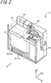
- FIG. 2 is a perspective view showing the appearance of an example of the fuel cell apparatus according to the present disclosure.
- the fuel cell apparatus with the exterior case (more specifically, four side panels, a top panel, etc. constituting the outer frame of the fuel cell apparatus) removed.
- the side panel will be also referred to simply as "side”.
- a face of the fuel cell apparatus as viewed in the direction of arrow A (or equivalently a y direction) in FIG. 2 is defined as a front face of the fuel cell apparatus 50.
- a rightward direction as viewed from the front face is defined as an x direction
- a height direction is defined as a z direction.
- the heat dissipator 50 is disposed below the fuel cell module 91, and, the heat-storage tank 40 is disposed on a lateral side of the fuel cell module 91 and the heat dissipator 50.
- a control board 93 for controlling the fuel cell apparatus 1 is disposed on a lateral side of the fuel cell module 91, and, a power conditioner 94 for supplying electric power produced by the fuel cell module 91 to outside is disposed on a lateral side of the heat-storage tank 40.
- an auxiliary machine 70 such as a fuel pump is disposed above the fuel cell module 91 to operate the fuel cell module 91.
- One or more auxiliary machines 70 are disposed inside a space indicated by a dotted line. The description of the specific configuration of the auxiliary machine will be omitted.
- the heat dissipator 50 includes a narrow piping of the radiator 51 through which the medium passes (refer to FIGS. 5A and 5B ). Disposing the heat dissipator 50 below the fuel cell module 91 enables protection of the fuel cell module 91 from trouble such as liquid leakage from the radiator. Moreover, disposing the heat dissipator 50 below the control board 93 and the power conditioner 94 enables protection of the control board 93 and the power conditioner 94 from trouble such as liquid leakage from the radiator. In addition, disposing the heat dissipator 50 below the fuel cell module 91 enables introduction of external air having a relatively low temperature, and thus can enhance the heat-dissipation efficiency.
- FIG. 3 is one side view of an example of the fuel cell apparatus according to the present embodiment, illustrating a side face 81 of an exterior case 80 having longitudinal sides.
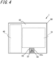
- FIG. 4 is the other side view of an example of the fuel cell apparatus according to the present embodiment, illustrating a side face 83 of the exterior case 80 opposite to the side face 81.
- the exterior case 80 for housing devices constituting the fuel cell apparatus 1 is shaped in a rectangular prism.
- an air inlet 54 and the radiator 51 of the heat dissipator 50 are disposed in a lower side opening 83a of the side face 83 of the exterior case 80.
- an air outlet 55 and the fan 52 of the heat dissipator 50 are disposed in a lower side opening 83a of the side face 83 of the exterior case 80.
- an opening area of the air inlet 54 is larger than an opening area of the air outlet 55. This makes it possible to increase the amount of air which is introduced from the air inlet 54, and thereby efficiently cool the medium flowing through the interior of the piping of the radiator 51. Moreover, forming the air inlet 54 in the large-area side face 81 allows the air inlet 54 to have a large opening area. In addition, an opening area of the opening 81a connected with the air inlet 54 can be larger than an opening area of the opening 83a connected with the air outlet 55.
- the fuel cell module 91 indicated by a broken line is disposed above the heat dissipator 50 to avoid any trouble associated with the heat dissipator 50, as well as to achieve an improvement in heat-dissipation efficiency in the heat dissipator 50.
- the heat-storage tank 40 is disposed adjacent to the fuel cell module 91.
- FIGS. 5A and 5B are each an exploded perspective view showing a specific example of the heat dissipator of the present embodiment.
- the heat dissipator 50 includes the radiator 51, the fan 52, an air flow channel 53, and a radiator duct (hereafter also referred to simply as "duct") 59.
- the duct 59 in the form of a frame body that defines the air flow channel 53, includes a plurality of separable parts. Thus, it is possible to achieve good maintainability.
- the duct 59 is made of resin and is thus lighter in weight than a metal-made duct. This facilitates duct servicing and maintenance.
- the duct 59 shown in FIG. 5A includes an upper duct 59A and a lower duct 59B.
- the upper duct 59A is illustrated as being separated from the lower duct 59B.
- FIG. 5B shows a case where the upper duct 59A includes a first duct 59A1 which is separable from the upper duct 59A.
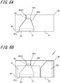
- FIGS. 6A and 6B are each a view schematically showing the heat dissipator of the present embodiment.
- FIG. 6A is an explanatory view of a structural example of the heat dissipator of the present embodiment, illustrating the structure of the heat dissipator 50 disposed over the bottom face of the exterior case 80, as seen in a plan view.
- the air flow channel 53 which is defined by the duct 59, may be communicated with other portions in the exterior case 80.
- air present in portions other than the heat dissipator 50 in the exterior case 80 can be discharged.
- FIG. 6B is a plan view showing the positional relationship between the heat dissipator of the present embodiment and other devices.
- the first duct 59A1 lies outside the range of the fuel cell module 91.
- the first duct 59A1 constitutes part of the upper duct 59A.
- the first duct 59A1 is separable from the upper duct 59, and it is thus possible to facilitate replacement of the fan 52 located below the first duct 59A1.
- FIGS. 7A and 7B are each an explanatory view of a structural example of the radiator duct of the present embodiment.
- FIG. 7A shows a case where part of the upper duct 59A is constituted by the first duct 59A1 as described above with reference to FIG. 6B .
- FIG. 7B shows another case where a first duct 59C is disposed independently of the upper duct 59A and the lower duct 59B.
- the first duct 59C can be separated completely from the upper duct 59A and the lower duct 59B, and it is thus possible to achieve good maintainability.
- Each constituent device of the fuel cell apparatus 11 is designed basically as is shown in the block diagram of FIG. 1 and the perspective view of FIG. 2 , and thus overlapping descriptions will be omitted.
- a heat dissipator 150 of the second embodiment is identical with that of the heat dissipator 50 of the foregoing first embodiment except for the shape of the air flow channel (refer to FIG. 10 , for example). Thus, the detailed description of the heat dissipator 150 will be omitted.
- FIG. 8 is a side view of an example of the fuel cell apparatus according to the present embodiment, illustrating a side face of an exterior case 80 having longitudinal sides.
- FIG. 9 is a side view of an example of the fuel cell apparatus according to this embodiment, illustrating a side face of the exterior case 80 having transverse sides.
- the exterior case 80 for housing devices constituting the fuel cell apparatus 11 is also shaped in a rectangular prism.
- An area of the side face 81 of the exterior case 80 is larger than an area of the side face 82 of the exterior case 80 contiguous to the side face 81.
- An air inlet 154 of the heat dissipator 150 is connected directly to an opening 181a formed in the large-area side face 81 so as to extend along the lower side of the side face 81, and, a radiator 151 is disposed in the air inlet 154.
- An air outlet 155 of the heat dissipator 150 is connected directly to an opening 182a formed in the small-area side face 82 so as to extend along the lower side of the side face 82, and, a fan 152 is disposed in the air outlet 155.
- the air inlet 154 and the air outlet 155 have been illustrated as being connected directly to the opening 181a and the opening 182a formed in the side face 81 and the side face 82, respectively. Also in cases where the air inlet 154 and the air outlet 155 are connected to their respective openings via air flow channels as described later, in the present embodiment, the air inlet 154 makes connection with the opening 181a formed in the side face 81, and the air outlet 155 makes connection with the opening 182a formed in the side face 82.
- the relationship in opening area between the air inlet 154 and the air outlet 155 is similar to the earlier described relationship in opening area between the air inlet 54 and the air outlet 55, and will thus not be described hereinbelow.
- the fuel cell apparatus is oriented so that the large-area side face 81 is located substantially parallel to a house wall. With the side face 81 located substantially parallel to the house wall, the contiguous side face 82 faces into open space correspondingly, thus enabling safe and effective exhaust from the air outlet 55 provided in the side face 82. Moreover, owing to the side face 82 facing into open space, maintainability can be improved.
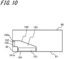
- FIG. 10 is an explanatory view of a structural example of the heat dissipator of the fuel cell apparatus according to the present embodiment, illustrating the structure of the heat dissipator 150 disposed over the bottom face of the exterior case 80, as seen in a plan view.
- the heat dissipator 150 includes the radiator 151, the fan 152, and an air flow channel 153.
- the operation of the fan 152 is identical with that of the earlier described fan 52 except that air that has passed through the radiator 151 passes through the fan 152 along the air flow channel 153 with a 90° turn. Thus, the description of the fan 152 will be omitted.
- the air flow channel 153 is defined by, in addition to a partition wall plate, for example, the outer wall of a constituent device disposed around the heat dissipator, these wall portions are not intended to isolate the air flow channel 153 completely from other portions than the heat dissipator.
- the air flow channel 153 may be communicated with other portions in the exterior case 80.
- the fan 152 in addition to air present in the heat dissipator 150, air present in portions other than the heat dissipator 150 in the exterior case 80 can be discharged.
- the air flow channel 153 is provided separately from other portions in the exterior case 80 for the purpose of cooling auxiliary machines, etc.
- an additional fan needs to be provided to ventilate the interior of the exterior case 80.
- discharge of air from both of the heat dissipator 150 and other portions in the exterior case 80, as well as replenishment of fresh air into both of them, can be carried out by a single fan 152. This eliminates the need to provide such an additional fan as above described, and thus reduces the number of fans in the fuel cell apparatus, with consequent downsizing of the fuel cell apparatus.
- the air inlet 154 is provided so as to make connection with the opening 181a provided in the side face 81 which is one side face of the exterior case 80.
- the air outlet 155 is provided so as to make connection with the opening 182a provided in the side face 82 which is the other face of the exterior case 80 contiguous to the side face 81.
- the air inlet 154 is provided so as to make connection with the opening 181a provided in the side face 81 of the exterior case 80, and, the air outlet 155 is provided so as to make connection with the opening 182a provided in the side face 82 contiguous to the side face 81.
- the air flow channel 153 bent in an L- or V-form constitutes resistance, and consequently external air is restrained from flowing to the interior through the air inlet 154. Consequently, since the medium flowing through the radiator 151 is not overcooled, it is possible to reduce deterioration in heat-storage performance in the heat-storage tank 40.
- the air inlet and the air outlet are provided so as to make connection with their respective openings provided in one common side face of the exterior case and to be located close to each other, for example, discharged air may flow into the air inlet once again, causing the efficiency of the heat dissipator to fall off.
- the air inlet 154 and the air outlet 155 so as to make connection with the opening 181a and the opening 182a, respectively, provided in different side faces contiguous to each other, the location for air introduction and the location for air discharge are separated from each other, and therefore it is possible to prevent a decrease in the cooling efficiency of the heat dissipator.
- an opening area of the air inlet 154 may be larger than an opening area of the air outlet 155.
- an opening area of the opening 181a connected with the air inlet 154 may be larger than an opening area of the opening 182a connected with the air outlet 155. This makes it possible to ensure the heat-dissipation capability of the radiator 151 located near the air inlet 154, and to reduce the size of the fan 152 located near the air outlet 155.
- FIG. 11 is an explanatory view of another structural example of the heat dissipator of the fuel cell apparatus according to the present embodiment.
- the heat dissipator 150 is disposed on an inward side of the fuel cell apparatus, the air inlet 154 is connected, through an air passageway 183, to the opening 181a provided in the side face 81, and, the air outlet 155 is connected, through an air passageway 184, to the opening 182a provided in the side face 82.
- This arrangement affords the same advantageous effects as achieved by the arrangement shown in FIG. 10 .
- FIG. 12 is an explanatory view of still another structural example of the heat dissipator of the fuel cell apparatus according to the present embodiment.
- an auxiliary machine 171 is disposed in the air flow channel 153 of the heat dissipator 150.
- Some of a plurality of auxiliary machines housed in the exterior case 80 include devices which get hot easily and thus exhibit high reliability when cooled, such as pumps.
- At least part of the plurality of auxiliary machines is disposed in the air flow channel 153 connecting the air inlet 154 and the air outlet 155. Thereby, it is possible to cool the mounted auxiliary machine 171 render the auxiliary machine highly reliable, and enhance the reliability of the fuel cell apparatus.
- FIG. 13 is an explanatory view of yet another structural example of the heat dissipator of the fuel cell apparatus according to the present embodiment.
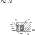
- FIG. 14 is a schematic sectional view of the heat dissipator of the fuel cell apparatus shown in FIG. 13 taken along the section line A-A of FIG. 13 .
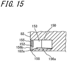
- FIG. 15 is a schematic sectional view of the heat dissipator of the fuel cell apparatus shown in FIG. 13 taken along the section line B-B of FIG. 13 .
- the present embodiment differs from the above-described fuel cell apparatus 10 shown in FIG. 10 in respect of the shape of the bottom face of the heat dissipator.
- FIGS. 10 differs from the above-described fuel cell apparatus 10 shown in FIG. 10 in respect of the shape of the bottom face of the heat dissipator.
- the cross-hatched area located outside the air flow channel 153 indicates a space where the fuel cell module 91, the auxiliary machine 70, etc. are disposed.
- the wall face of the air flow channel 153 is defined by a partition plate such as a metallic plate or part of the enclosures of devices mounted around the heat dissipator 150.
- the air inlet 154 is provided so as to make connection with the opening 181a provided in the side face 81 of the exterior case 80, and, the air outlet 155 is provided so as to make connection with the opening 182a provided in the side face 82 contiguous to the side face 81.
- the air flow channel 153 connecting the air inlet 154 and the air outlet 155 is bent in an L-form in the exterior case 80.
- the bottom face of the air flow channel 153 defined by a metal-made partition plate, etc. includes a bottom face 156a opposed to the air inlet 154 and a bottom face 156b opposed to the air outlet 155.
- the radiator 151 is disposed above the bottom face 156a opposed to the opening 181a (hereafter also referred to as the air inlet 154 in the following embodiment).
- the bottom face 156a slopes downwardly from an inward side of the air flow channel 153, for example, the bend of the L-shaped air flow channel 53, toward the air inlet 154.
- the fan 152 is disposed above the bottom face 156b opposed to the opening 182a (hereafter also referred to as the air outlet 155 in the following embodiment.
- the bottom face 156b slopes downwardly from an inward side of the air flow channel 153, for example, the bend of the L-shaped air flow channel 153, toward the air outlet 155.
- each bottom face be free from any upward incline on its way to the opening. That is, for example, the bottom face may be configured to have a continuous slope, to have a slope which is partly made flat, or to have a stepped slope. Note that, where a drain hole is provided as described later, the bottom face may be configured to slope downwardly only to the location corresponding to the drain hole.
- the bottom face 156a may be provided with a drain hole 157 located below the radiator 151 and near the air inlet 154.
- the bottom face 156b may be provided with a drain hole 158 located below the fan 152 and near the air outlet 155.
- the shape and number of the drain holes 157 and 158 are determined in conformance with the shapes of the air inlet 54 and the air outlet 155.
- the drain hole 157 is located near the air inlet 154, whereas the drain hole 158 is located near the air outlet 155 in the present embodiment, the drain hole 157 may be located in any position of the bottom face 156a, and the drain hole 158 may also be located in any position of the bottom face 156b.
- the drain holes 157 and 158 considering the entry of water such as rain water from the air inlet 154, the water present on the bottom face 156a can be discharged from the drain hole 157 located near the air inlet 154, and also, considering the entry of water such as rain water from the air outlet 155, the water present on the bottom face 156b can be discharged from the drain hole 158 located near the air outlet 155.
- the bottom face may slope downwardly from the inward side of the air flow channel 153 toward each of the drain holes 157 and 158, as well as slope downwardly from each of the air inlet 154 and the air outlet 155 to each of the drain holes 157 and 158.
- the water entered can be collected in each of the drain holes 157 and 158 and flow therefrom.
- drain holes 157 and 158 it is possible to discharge water which has entered through the air inlet 154 or the air outlet 155 without causing the water to flow over the surface of the exterior case 80. Moreover, since the drain holes 157 and 158 are provided inside the exterior case 80 (in other words, provided in the heat dissipator 150 or the air passageways 183 and 184), even under a substantial external wind pressure, the water entered can be discharged smoothly without being influenced by the wind pressure.
- a water supply pipe may be connected to the drain holes 157 and 158 to direct discharged water toward the bottom of the fuel cell apparatus 11 or away from the fuel cell apparatus 11.
- the air inlet 154 is connected, through the air passageway 183, to the opening 181a provided in the side face 81, or the air outlet 155 is connected, through the air passageway 184, to the opening 182a provided in the side face 82.
- the air passageway 183 may be configured to slope downwardly toward the opening 181a, or the air passageway 184 may be configured to slope downwardly toward the opening 182a.
- the air passageways 183 and 184 may be provided with a drain hole.
Landscapes
- Engineering & Computer Science (AREA)
- Chemical & Material Sciences (AREA)
- Chemical Kinetics & Catalysis (AREA)
- Sustainable Development (AREA)
- Sustainable Energy (AREA)
- Manufacturing & Machinery (AREA)
- Life Sciences & Earth Sciences (AREA)
- Electrochemistry (AREA)
- General Chemical & Material Sciences (AREA)
- Combustion & Propulsion (AREA)
- Physics & Mathematics (AREA)
- Thermal Sciences (AREA)
- Mechanical Engineering (AREA)
- General Engineering & Computer Science (AREA)
- Fuel Cell (AREA)
Abstract
Description
- The present invention relates to a fuel cell apparatus.
- In recent years, as next-generation energy sources, there have been proposed various fuel cell modules of the type including a cell stack, which is housed in a housing, including a plurality of stacked fuel cells capable of obtaining electric power by utilizing a fuel gas (hydrogen-containing gas) and air (oxygen-containing gas), and also fuel cell apparatuses each including such a fuel cell module housed in an exterior case.
- There is another proposal as to a fuel cell apparatus including a heat storage tank, in which a heat exchanger carries out heat exchange between exhaust gas from a fuel cell module and a medium such as water to cool the exhaust gas for recovery and reuse of water contained in the exhaust gas, and also the heat recovered by the medium is utilized for the supply of hot water.
- Moreover, there is a disclosure of a technique to supply a medium to a heat exchanger after lowering the temperature of the medium by a heat dissipator disposed between a heat-storage tank and the heat exchanger. For example,
Patent Literature 1 discloses a construction in which an exterior case has an air inlet provided in one surface thereof and an air outlet provided in the opposite surface thereof, and, Patent Literature 2 discloses a construction in which an exterior case has an air inlet and an air outlet for a heat dissipator provided in one and the same surface thereof. - Furthermore, with regard to exhaust air flow control in a heat dissipator, for example, Patent Literatures 3 and 4 disclose a fuel cell apparatus having an air flow channel such as a duct.
-
- Patent Literature 1: Japanese Unexamined Patent Publication
JP-A 2009-38015 - Patent Literature 2: Japanese Unexamined Patent Publication
JP-A 2015-72090 - Patent Literature 3: Japanese Unexamined Patent Publication
JP-A 2010-92775 - Patent Literature 4: Japanese Unexamined Patent Publication
JP-A 2016-217670 - A fuel cell apparatus according to the present disclosure comprises: a fuel cell module; a heat exchanger which carries out heat exchange between exhaust gas from the fuel cell module and a medium; a circulation line connected to the heat exchanger, the circulation line allowing the medium to circulate the heat exchanger; a heat dissipator located in the circulation line, the heat dissipator cooling the medium flowing through the heat exchanger; and an exterior case which houses the fuel cell module, the heat exchanger, the heat dissipator, and at least part of the circulation line.
- The heat dissipator is provided with two openings. The heat dissipator includes at least a duct which defines an air flow channel between the two openings; a fan located closer to one opening of the two openings than the other opening in the air flow channel, the fan producing flowing air; and a radiator located closer to the other opening of the two openings than the one opening in the air flow channel, the radiator carrying out heat exchange between the medium and air flowing through an interior of the air flow channel.
- The exterior case is provided with two ventilation holes to which the two openings are connected directly or via an air passageway, respectively, and the duct comprises a plurality of separable parts.
- Other and further objects, features, and advantages of the invention will be more explicit from the following detailed description taken with reference to the drawings wherein:
-
FIG. 1 is a block diagram showing the structure of an example of a fuel cell apparatus according to the present disclosure; -
FIG. 2 is a perspective view showing the appearance of an example of the fuel cell apparatus according to the present disclosure; -
FIG. 3 is one side view of an example of the fuel cell apparatus according to a first embodiment; -
FIG. 4 is another side view of an example of the fuel cell apparatus according to the first embodiment; -
FIG. 5A is an exploded perspective view showing a specific example of a heat dissipator of the first embodiment; -
FIG. 5B is an exploded perspective view showing a specific example of the heat dissipator of the first embodiment; -
FIG. 6A is a view schematically showing the heat dissipator of the first embodiment; -
FIG. 6B is a view schematically showing the heat dissipator of the first embodiment; -
FIG. 7A is an explanatory view of a structural example of a radiator duct of the first embodiment; -
FIG. 7B is an explanatory view of a structural example of the radiator duct of the firs embodiment; -
FIG. 8 is a side view of an example of a fuel cell apparatus according to a second embodiment; -
FIG. 9 is a side view of an example of the fuel cell apparatus according to the second embodiment; -
FIG. 10 is an explanatory view of a structural example of a heat dissipator of the fuel cell apparatus according to the second embodiment; -
FIG. 11 is an explanatory view of another structural example of the heat dissipator of the fuel cell apparatus according to the second embodiment; -
FIG. 12 is an explanatory view of another structural example of the heat dissipator of the fuel cell apparatus according to the second embodiment; -
FIG. 13 is an explanatory view of another structural example of the heat dissipator of the fuel cell apparatus according to the second embodiment; -
FIG. 14 is a schematic sectional view of the heat dissipator of the fuel cell apparatus shown inFIG. 13 ; and -
FIG. 15 is a schematic sectional view of the heat dissipator of the fuel cell apparatus shown inFIG. 13 . - Disposing a heat dissipator in a lower part of a fuel cell apparatus causes complications in maintenance operation. Thus, ease of maintenance has been demanded in a heat dissipator which is located in a fuel cell apparatus. The following describes fuel cell apparatuses according to embodiments of the invention in sequence.
-
FIG. 1 is a block diagram showing the structure of an example of a fuel cell apparatus according to the present disclosure. Throughout the drawings to be hereafter referred to, the same reference numerals or symbols designate corresponding or identical constituent components. Afuel cell apparatus 1 according to the first embodiment includes areformer 10, a cell stack device 20, aheat exchanger 30, a heat-storage tank 40, aheat dissipator 50, and a condensedwater tank 60. Each such constituent device is, together with auxiliary machines which operate afuel cell module 91 as described later, housed in an exterior case, not shown. It is not necessary to house all of the aforenamed devices in the exterior case, and for example, the heat-storage tank 40 and theheat exchanger 30 may be disposed outside the exterior case. Moreover, the fuel cell apparatus in which apart of the aforenamed devices is omitted is also possible. - A raw
fuel supply pipe 100 which supplies a raw fuel and awater supply pipe 101 which supplies reformed water are connected to thereformer 10. Inside the heatedreformer 10, the raw fuel and the reformed water undergo reforming reactions with each other to produce a hydrogen-containing reformed gas. The reformed gas produced in thereformer 10 is supplied to the cell stack device 20 through a reformedgas supply pipe 102. - The cell stack device 20 includes a
manifold 21 and a cell stack 22. the reformed gas supplied to the cell stack device 20 is supplied from themanifold 21 into the cell stack 22. In the cell stack device 20, air (oxygen-containing gas) is introduced from an oxygen-containinggas supply member 103 outside the cell stack 22. When passing through the interior of the cell stack 22, the reformed gas reacts with this air to carry out power generation. In a region above the cell stack 22, reformed gas left unused for power generation merges with air left unused for power generation, and the resulting confluent flow is burned to produce high-temperature exhaust gas. Moreover, thereformer 10 is heated under heat resulting from the combustion. - The
reformer 10 and the cell stack device 20 are brought into high-temperature conditions, and are encased by a heat-insulating material and are placed inside the exterior case as thefuel cell module 91. - Exhaust gas generated in the
fuel cell module 91 is discharged from the cell stack device 20, and is then supplied to theheat exchanger 30 through an exhaustgas flow channel 104. Acirculation line 105 is connected to theheat exchanger 30 to carry out heat exchange between the exhaust gas and a medium introduced in thecirculation line 105. As the medium, it is possible to use a non-freezing liquid containing ethylene glycol, etc., or water. Under the heat exchange, the exhaust gas is cooled, whereas the medium is heated by the heat of the exhaust gas. Due to the cooling of the exhaust gas, water vapor contained in the exhaust gas becomes water, with consequent occurrence of vapor-liquid separation. The separated gas is discharged through anexhaust channel 107 from a gas exhaust outlet externally. The water separated by the cooling of the exhaust gas is delivered through a condensedwater recovery channel 106 to thecondensed water tank 60. In thecondensed water tank 60, the water is purified into pure water through an ion exchange process or otherwise. The pure water is introduced into thewater supply pipe 101, and is then supplied, as reformed water, to thereformer 10. Unnecessary water is ejected from adrain 109. - The medium is circulated successively through the heat-
storage tank 40, theheat dissipator 50, and theheat exchanger 30 in the order named. The medium is stored in the heat-storage tank 40. After being delivered from the heat-storage tank 4 to theheat dissipator 50, the medium is cooled, and then supplied to theheat exchanger 30. In theheat exchanger 30, the medium is heated by heat exchange with the exhaust gas. The medium having an elevated temperature is returned to the heat-storage tank 40. - That is, there is formed the
circulation line 105 in which the medium is circulated successively through the heat-storage tank 40, theheat dissipator 50, and theheat exchanger 30 in the order named. In other words, the heat-storage tank 40, theheat dissipator 50, and theheat exchanger 30 are disposed successively in the order named along thecirculation line 105. - A hot water supply piping is introduced in the heat-
storage tank 40 to utilize heated water resulting from heat exchange between water delivered from awater supply pipe 108 and the medium stored in the heat-storage tank 40 as hot water. Where water is used as the medium, the fuel cell apparatus may be configured so as to supply the medium as hot water per se. - When the amount of heat accumulated in the heat-
storage tank 40 reaches the upper limit (full heat storage state), the medium is no longer able to recover the heat of the exhaust gas in theheat exchanger 30, and consequently the exhaust gas cannot be cooled sufficiently, causing a failure in the separation of moisture from the exhaust gas. As a result, a failure in condensation of moisture contained in the exhaust gas may lead to a shortage of water which is supplied to thereformer 10. Accordingly, it is necessary to decrease the temperature of the medium which is supplied to theheat exchanger 30. In thefuel cell apparatus 1 according to the present embodiment, the medium is cooled by theheat dissipator 50 and to then supplied to theheat exchanger 30. Theheat dissipator 50 includes aradiator 51 and afan 52. When the medium is at a high temperature, thefan 52 is actuated to facilitate dissipation of heat from the medium passing through the interior of theradiator 51. On the other hand, when the medium is at a low temperature, thefan 52 is left unactuated to restrain dissipation of heat from the medium in theheat dissipator 50. -
FIG. 2 is a perspective view showing the appearance of an example of the fuel cell apparatus according to the present disclosure. InFIG. 2 , for purposes of explanation of the interior of the fuel cell apparatus, there is shown the fuel cell apparatus with the exterior case (more specifically, four side panels, a top panel, etc. constituting the outer frame of the fuel cell apparatus) removed. In the following description, the side panel will be also referred to simply as "side". For purposes of convenience, a face of the fuel cell apparatus as viewed in the direction of arrow A (or equivalently a y direction) inFIG. 2 is defined as a front face of thefuel cell apparatus 50. Moreover, a rightward direction as viewed from the front face is defined as an x direction, and a height direction is defined as a z direction. In thefuel cell apparatus 1, theheat dissipator 50 is disposed below thefuel cell module 91, and, the heat-storage tank 40 is disposed on a lateral side of thefuel cell module 91 and theheat dissipator 50. - Moreover, a
control board 93 for controlling thefuel cell apparatus 1 is disposed on a lateral side of thefuel cell module 91, and, apower conditioner 94 for supplying electric power produced by thefuel cell module 91 to outside is disposed on a lateral side of the heat-storage tank 40. In addition, anauxiliary machine 70 such as a fuel pump is disposed above thefuel cell module 91 to operate thefuel cell module 91. One or moreauxiliary machines 70 are disposed inside a space indicated by a dotted line. The description of the specific configuration of the auxiliary machine will be omitted. - The
heat dissipator 50 includes a narrow piping of theradiator 51 through which the medium passes (refer toFIGS. 5A and 5B ). Disposing theheat dissipator 50 below thefuel cell module 91 enables protection of thefuel cell module 91 from trouble such as liquid leakage from the radiator. Moreover, disposing theheat dissipator 50 below thecontrol board 93 and thepower conditioner 94 enables protection of thecontrol board 93 and thepower conditioner 94 from trouble such as liquid leakage from the radiator. In addition, disposing theheat dissipator 50 below thefuel cell module 91 enables introduction of external air having a relatively low temperature, and thus can enhance the heat-dissipation efficiency. -
FIG. 3 is one side view of an example of the fuel cell apparatus according to the present embodiment, illustrating aside face 81 of anexterior case 80 having longitudinal sides.FIG. 4 is the other side view of an example of the fuel cell apparatus according to the present embodiment, illustrating aside face 83 of theexterior case 80 opposite to theside face 81. As shown inFIG. 3 , theexterior case 80 for housing devices constituting thefuel cell apparatus 1 is shaped in a rectangular prism. In alower side opening 81a of theside face 81 of theexterior case 80, anair inlet 54 and theradiator 51 of theheat dissipator 50 are disposed. On the other hand, as shown inFIG. 4 , in alower side opening 83a of theside face 83 of theexterior case 80, anair outlet 55 and thefan 52 of theheat dissipator 50 are disposed. - As shown in
FIGS. 3 and4 , an opening area of theair inlet 54 is larger than an opening area of theair outlet 55. This makes it possible to increase the amount of air which is introduced from theair inlet 54, and thereby efficiently cool the medium flowing through the interior of the piping of theradiator 51. Moreover, forming theair inlet 54 in the large-area side face 81 allows theair inlet 54 to have a large opening area. In addition, an opening area of theopening 81a connected with theair inlet 54 can be larger than an opening area of theopening 83a connected with theair outlet 55. - As described above, the
fuel cell module 91 indicated by a broken line is disposed above theheat dissipator 50 to avoid any trouble associated with theheat dissipator 50, as well as to achieve an improvement in heat-dissipation efficiency in theheat dissipator 50. The heat-storage tank 40 is disposed adjacent to thefuel cell module 91. -
FIGS. 5A and 5B are each an exploded perspective view showing a specific example of the heat dissipator of the present embodiment. Theheat dissipator 50 includes theradiator 51, thefan 52, anair flow channel 53, and a radiator duct (hereafter also referred to simply as "duct") 59. Theduct 59, in the form of a frame body that defines theair flow channel 53, includes a plurality of separable parts. Thus, it is possible to achieve good maintainability. Moreover, for example, theduct 59 is made of resin and is thus lighter in weight than a metal-made duct. This facilitates duct servicing and maintenance. - The
duct 59 shown inFIG. 5A includes anupper duct 59A and alower duct 59B. InFIG. 5A , theupper duct 59A is illustrated as being separated from thelower duct 59B. By designing theduct 59 so that theupper duct 59A can be separated from thelower duct 59B, it is possible to achieve good maintainability. -
FIG. 5B shows a case where theupper duct 59A includes a first duct 59A1 which is separable from theupper duct 59A. By designing theduct 59 so that the first duct 59A1 can be separated from theupper duct 59A, it is possible to achieve good maintainability for thefan 52, etc. located below the first duct 59A1. -
FIGS. 6A and 6B are each a view schematically showing the heat dissipator of the present embodiment.FIG. 6A is an explanatory view of a structural example of the heat dissipator of the present embodiment, illustrating the structure of theheat dissipator 50 disposed over the bottom face of theexterior case 80, as seen in a plan view. - Upon actuation of the
fan 52 of theheat dissipator 50, air is introduced from theair inlet 54 connected to theopening 81a formed in theside face 81 under negative pressure, and, the medium flowing through the interior of the piping is cooled when the air passes through theradiator 51. After passing through theradiator 51, the air passes through theair flow channel 53 and thefan 52, and is eventually discharged from theair outlet 55 connected to theopening 83a formed in theside face 83. - The
air flow channel 53, which is defined by theduct 59, may be communicated with other portions in theexterior case 80. In this case, by the operation of thefan 52, in addition to air present in theheat dissipator 50, air present in portions other than theheat dissipator 50 in theexterior case 80 can be discharged. -
FIG. 6B is a plan view showing the positional relationship between the heat dissipator of the present embodiment and other devices. As shown inFIG. 6B , in theheat dissipator 50 as seen in a transparent plan view, the first duct 59A1 lies outside the range of thefuel cell module 91. The first duct 59A1 constitutes part of theupper duct 59A. The first duct 59A1 is separable from theupper duct 59, and it is thus possible to facilitate replacement of thefan 52 located below the first duct 59A1. -
FIGS. 7A and 7B are each an explanatory view of a structural example of the radiator duct of the present embodiment.FIG. 7A shows a case where part of theupper duct 59A is constituted by the first duct 59A1 as described above with reference toFIG. 6B .FIG. 7B shows another case where afirst duct 59C is disposed independently of theupper duct 59A and thelower duct 59B. In this structure, during maintenance operation, thefirst duct 59C can be separated completely from theupper duct 59A and thelower duct 59B, and it is thus possible to achieve good maintainability. - The following describes a
fuel cell apparatus 11 according to a second embodiment. Each constituent device of thefuel cell apparatus 11 is designed basically as is shown in the block diagram ofFIG. 1 and the perspective view ofFIG. 2 , and thus overlapping descriptions will be omitted. - Moreover, the function of a
heat dissipator 150 of the second embodiment is identical with that of theheat dissipator 50 of the foregoing first embodiment except for the shape of the air flow channel (refer toFIG. 10 , for example). Thus, the detailed description of theheat dissipator 150 will be omitted. -
FIG. 8 is a side view of an example of the fuel cell apparatus according to the present embodiment, illustrating a side face of anexterior case 80 having longitudinal sides.FIG. 9 is a side view of an example of the fuel cell apparatus according to this embodiment, illustrating a side face of theexterior case 80 having transverse sides. Theexterior case 80 for housing devices constituting thefuel cell apparatus 11 is also shaped in a rectangular prism. An area of theside face 81 of theexterior case 80 is larger than an area of theside face 82 of theexterior case 80 contiguous to theside face 81. - An
air inlet 154 of theheat dissipator 150 is connected directly to anopening 181a formed in the large-area side face 81 so as to extend along the lower side of theside face 81, and, aradiator 151 is disposed in theair inlet 154. - An
air outlet 155 of theheat dissipator 150 is connected directly to anopening 182a formed in the small-area side face 82 so as to extend along the lower side of theside face 82, and, afan 152 is disposed in theair outlet 155. - The
air inlet 154 and theair outlet 155 have been illustrated as being connected directly to theopening 181a and theopening 182a formed in theside face 81 and theside face 82, respectively. Also in cases where theair inlet 154 and theair outlet 155 are connected to their respective openings via air flow channels as described later, in the present embodiment, theair inlet 154 makes connection with theopening 181a formed in theside face 81, and theair outlet 155 makes connection with theopening 182a formed in theside face 82. - The relationship in opening area between the
air inlet 154 and theair outlet 155 is similar to the earlier described relationship in opening area between theair inlet 54 and theair outlet 55, and will thus not be described hereinbelow. - In setting such a rectangular prism-shaped fuel cell apparatus, especially in a residential house, in most cases, the fuel cell apparatus is oriented so that the large-area side face 81 is located substantially parallel to a house wall. With the
side face 81 located substantially parallel to the house wall, the contiguous side face 82 faces into open space correspondingly, thus enabling safe and effective exhaust from theair outlet 55 provided in theside face 82. Moreover, owing to theside face 82 facing into open space, maintainability can be improved. -
FIG. 10 is an explanatory view of a structural example of the heat dissipator of the fuel cell apparatus according to the present embodiment, illustrating the structure of theheat dissipator 150 disposed over the bottom face of theexterior case 80, as seen in a plan view. Theheat dissipator 150 includes theradiator 151, thefan 152, and anair flow channel 153. - The operation of the
fan 152 is identical with that of the earlier describedfan 52 except that air that has passed through theradiator 151 passes through thefan 152 along theair flow channel 153 with a 90° turn. Thus, the description of thefan 152 will be omitted. - While the
air flow channel 153 is defined by, in addition to a partition wall plate, for example, the outer wall of a constituent device disposed around the heat dissipator, these wall portions are not intended to isolate theair flow channel 153 completely from other portions than the heat dissipator. Thus, theair flow channel 153 may be communicated with other portions in theexterior case 80. In this case, by the operation of thefan 152, in addition to air present in theheat dissipator 150, air present in portions other than theheat dissipator 150 in theexterior case 80 can be discharged. Where theair flow channel 153 is provided separately from other portions in theexterior case 80 for the purpose of cooling auxiliary machines, etc. mounted in theexterior case 80, an additional fan needs to be provided to ventilate the interior of theexterior case 80. In this regard, in the present embodiment, discharge of air from both of theheat dissipator 150 and other portions in theexterior case 80, as well as replenishment of fresh air into both of them, can be carried out by asingle fan 152. This eliminates the need to provide such an additional fan as above described, and thus reduces the number of fans in the fuel cell apparatus, with consequent downsizing of the fuel cell apparatus. - That is, as shown in
FIG. 10 , in theheat dissipator 150 of the present embodiment, theair inlet 154 is provided so as to make connection with theopening 181a provided in theside face 81 which is one side face of theexterior case 80. Moreover, theair outlet 155 is provided so as to make connection with theopening 182a provided in theside face 82 which is the other face of theexterior case 80 contiguous to theside face 81. This arrangement reduces the size of theheat dissipator 150, and thus makes it possible to downsize the fuel cell apparatus. - Moreover, as shown in
FIG. 10 , theair inlet 154 is provided so as to make connection with theopening 181a provided in theside face 81 of theexterior case 80, and, theair outlet 155 is provided so as to make connection with theopening 182a provided in theside face 82 contiguous to theside face 81. In this case, even when theair inlet 154 faces windward, theair flow channel 153 bent in an L- or V-form constitutes resistance, and consequently external air is restrained from flowing to the interior through theair inlet 154. Consequently, since the medium flowing through theradiator 151 is not overcooled, it is possible to reduce deterioration in heat-storage performance in the heat-storage tank 40. - If the air inlet and the air outlet are provided so as to make connection with their respective openings provided in one common side face of the exterior case and to be located close to each other, for example, discharged air may flow into the air inlet once again, causing the efficiency of the heat dissipator to fall off. In this regard, by providing the
air inlet 154 and theair outlet 155 so as to make connection with theopening 181a and theopening 182a, respectively, provided in different side faces contiguous to each other, the location for air introduction and the location for air discharge are separated from each other, and therefore it is possible to prevent a decrease in the cooling efficiency of the heat dissipator. - Moreover, an opening area of the
air inlet 154 may be larger than an opening area of theair outlet 155. In addition, an opening area of theopening 181a connected with theair inlet 154 may be larger than an opening area of theopening 182a connected with theair outlet 155. This makes it possible to ensure the heat-dissipation capability of theradiator 151 located near theair inlet 154, and to reduce the size of thefan 152 located near theair outlet 155. -
FIG. 11 is an explanatory view of another structural example of the heat dissipator of the fuel cell apparatus according to the present embodiment. Where theheat dissipator 150 is disposed on an inward side of the fuel cell apparatus, theair inlet 154 is connected, through anair passageway 183, to theopening 181a provided in theside face 81, and, theair outlet 155 is connected, through anair passageway 184, to theopening 182a provided in theside face 82. This arrangement affords the same advantageous effects as achieved by the arrangement shown inFIG. 10 . -
FIG. 12 is an explanatory view of still another structural example of the heat dissipator of the fuel cell apparatus according to the present embodiment. As a point of difference from the arrangement shown inFIG. 10 , anauxiliary machine 171 is disposed in theair flow channel 153 of theheat dissipator 150. Some of a plurality of auxiliary machines housed in theexterior case 80 include devices which get hot easily and thus exhibit high reliability when cooled, such as pumps. At least part of the plurality of auxiliary machines is disposed in theair flow channel 153 connecting theair inlet 154 and theair outlet 155. Thereby, it is possible to cool the mountedauxiliary machine 171 render the auxiliary machine highly reliable, and enhance the reliability of the fuel cell apparatus. -
FIG. 13 is an explanatory view of yet another structural example of the heat dissipator of the fuel cell apparatus according to the present embodiment.FIG. 14 is a schematic sectional view of the heat dissipator of the fuel cell apparatus shown inFIG. 13 taken along the section line A-A ofFIG. 13 . Moreover,FIG. 15 is a schematic sectional view of the heat dissipator of the fuel cell apparatus shown inFIG. 13 taken along the section line B-B ofFIG. 13 . The present embodiment differs from the above-describedfuel cell apparatus 10 shown inFIG. 10 in respect of the shape of the bottom face of the heat dissipator. InFIGS. 14 and15 , the cross-hatched area located outside theair flow channel 153 indicates a space where thefuel cell module 91, theauxiliary machine 70, etc. are disposed. The wall face of theair flow channel 153 is defined by a partition plate such as a metallic plate or part of the enclosures of devices mounted around theheat dissipator 150. - The
air inlet 154 is provided so as to make connection with theopening 181a provided in theside face 81 of theexterior case 80, and, theair outlet 155 is provided so as to make connection with theopening 182a provided in theside face 82 contiguous to theside face 81. Theair flow channel 153 connecting theair inlet 154 and theair outlet 155 is bent in an L-form in theexterior case 80. The bottom face of theair flow channel 153 defined by a metal-made partition plate, etc. includes abottom face 156a opposed to theair inlet 154 and abottom face 156b opposed to theair outlet 155. - Above the
bottom face 156a opposed to theopening 181a (hereafter also referred to as theair inlet 154 in the following embodiment), theradiator 151 is disposed. Thebottom face 156a slopes downwardly from an inward side of theair flow channel 153, for example, the bend of the L-shapedair flow channel 53, toward theair inlet 154. Moreover, above thebottom face 156b opposed to theopening 182a (hereafter also referred to as theair outlet 155 in the following embodiment), thefan 152 is disposed. Thebottom face 156b slopes downwardly from an inward side of theair flow channel 153, for example, the bend of the L-shapedair flow channel 153, toward theair outlet 155. - In forming the bottom faces sloping downwardly toward the
openings - Assuming the entry of water such as rain water from the
air inlet 154, since thebottom face 156a slopes downwardly toward theair inlet 154, the water present on thebottom face 156a flows toward theair inlet 154. This makes it possible to suppress the retention of water in theheat dissipator 150. Moreover, assuming the entry of water such as rain water from theair outlet 155, since thebottom face 156b slopes downwardly toward theair outlet 155, the water present on thebottom face 156b flows toward theair outlet 155. This makes it possible to suppress the retention of water in theheat dissipator 150. - The
bottom face 156a may be provided with adrain hole 157 located below theradiator 151 and near theair inlet 154. Moreover, thebottom face 156b may be provided with adrain hole 158 located below thefan 152 and near theair outlet 155. The shape and number of the drain holes 157 and 158 are determined in conformance with the shapes of theair inlet 54 and theair outlet 155. Although thedrain hole 157 is located near theair inlet 154, whereas thedrain hole 158 is located near theair outlet 155 in the present embodiment, thedrain hole 157 may be located in any position of thebottom face 156a, and thedrain hole 158 may also be located in any position of thebottom face 156b. - As the advantages of formation of the drain holes 157 and 158, considering the entry of water such as rain water from the
air inlet 154, the water present on thebottom face 156a can be discharged from thedrain hole 157 located near theair inlet 154, and also, considering the entry of water such as rain water from theair outlet 155, the water present on thebottom face 156b can be discharged from thedrain hole 158 located near theair outlet 155. - Only when the drain holes 157 and 158 are provided, the bottom face may slope downwardly from the inward side of the
air flow channel 153 toward each of the drain holes 157 and 158, as well as slope downwardly from each of theair inlet 154 and theair outlet 155 to each of the drain holes 157 and 158. In this case, the water entered can be collected in each of the drain holes 157 and 158 and flow therefrom. - Thus, by providing the drain holes 157 and 158, it is possible to discharge water which has entered through the
air inlet 154 or theair outlet 155 without causing the water to flow over the surface of theexterior case 80. Moreover, since the drain holes 157 and 158 are provided inside the exterior case 80 (in other words, provided in theheat dissipator 150 or theair passageways 183 and 184), even under a substantial external wind pressure, the water entered can be discharged smoothly without being influenced by the wind pressure. - In the present embodiment, there may be a case where the
heat dissipator 150 is disposed in other location than the lowermost part of theexterior case 80. In such a case, a water supply pipe may be connected to the drain holes 157 and 158 to direct discharged water toward the bottom of thefuel cell apparatus 11 or away from thefuel cell apparatus 11. Moreover, there may be a case where theair inlet 154 is connected, through theair passageway 183, to theopening 181a provided in theside face 81, or theair outlet 155 is connected, through theair passageway 184, to theopening 182a provided in theside face 82. In this case, theair passageway 183 may be configured to slope downwardly toward theopening 181a, or theair passageway 184 may be configured to slope downwardly toward theopening 182a. Besides, theair passageways - Thus, since water which has entered the
heat dissipator 150 flows toward theair inlet 154 or theair outlet 155, this avoids the retention of water in theheat dissipator 150, and thus protects theheat dissipator 150 from corrosion. Moreover, since the water which has entered can be discharged from the drain holes 157 and 158, this protects theheat dissipator 150 from corrosion. In consequence, a highly durable fuel cell apparatus is provided. - The present disclosure has been described in detail, it being understood that the present disclosure is not limited to the embodiments as described heretofore, and various changes, modifications, and improvements are possible without departing from the scope of the present disclosure.
-
- 1, 11: Fuel cell apparatus
- 10: Reformer
- 20: Cell stack
- 30: Heat exchanger
- 40: Heat-storage tank
- 50, 150: Heat dissipator
- 51, 151: Radiator
- 52, 152: Fan
- 53, 153: Air flow channel
- 54, 154: Air inlet
- 55, 155: Air outlet
- 156a, 156b: Bottom face
- 157, 158: Drain hole
- 59: Radiator duct
- 59A: Upper duct
- 59B: Lower duct
- 59A1, 59C: First duct
- 60: Condensed water tank
- 70, 71: Auxiliary machine
- 80, 180: Exterior case
- 81, 82, 83: Side face
- 81a, 83a, 181a, 182a: Opening
- 83, 84, 183, 184: Air flow channel
- 91: Fuel cell module
- 105: Circulation line
Claims (12)
- A fuel cell apparatus, comprising:a fuel cell module;a heat exchanger which carries out heat exchange between exhaust gas from the fuel cell module and a medium;a circulation line connected to the heat exchanger, the circulation line allowing the medium to circulate the heat exchanger;a heat dissipator located in the circulation line, the heat dissipator cooling the medium flowing through the heat exchanger; andan exterior case which houses the fuel cell module, the heat exchanger, the heat dissipator, and at least part of the circulation line,the heat dissipator provided with two openings, the heat dissipator comprising at leasta duct which defines an air flow channel between the two openings;a fan located closer to one opening of the two openings than the other opening in the air flow channel, the fan producing flowing air; anda radiator located closer to the other opening of the two openings than the one opening in the air flow channel, the radiator carrying out heat exchange between the medium and air flowing through an interior of the air flow channel,the exterior case provided with two ventilation holes to which the two openings are connected directly or via an air passageway, respectively,the duct comprising a plurality of separable parts.
- The fuel cell apparatus according to claim 1, wherein
the heat dissipator is located below the fuel cell module. - The fuel cell apparatus according to claim 1 or 2, wherein
the plurality of separable parts of the duct include at least a first duct located close to the one opening. - The fuel cell apparatus according to claim 3, wherein
the plurality of separable parts of the duct include, in addition to the first duct, an upper duct and a lower duct which are vertically separatable from each other. - The fuel cell apparatus according to claim 3 or 4, wherein
at least the first duct lies outside a range of the fuel cell module, as seen in a transparent plan view of the fuel cell apparatus. - The fuel cell apparatus according to any one of claims 1 to 5, wherein
the duct is made of resin. - The fuel cell apparatus according to any one of claims 1 to 6, wherein
the fan operates to discharge, in addition to air introduced from the ventilation hole, air present in portions other than the heat dissipator in the exterior case. - The fuel cell apparatus according to any one of claims 1 to 7, wherein
a bottom face of the heat dissipator or a bottom face of the air passageway slopes downwardly toward the one opening or the other opening. - The fuel cell apparatus according to any one of claims 1 to 8, wherein
a bottom face of the heat dissipator or a bottom face of the air passageway is provided with a drain hole. - The fuel cell apparatus according to any one of claims 1 to 9, wherein
the duct is provided with an air outlet located close to the one opening, and an air inlet located close to the other opening, and
an opening area of the air inlet is greater than an opening area of the air outlet. - The fuel cell apparatus according to any one of claims 1 to 10, wherein
the ventilation hole connected to the one opening is disposed in one side face of the exterior case, and
the ventilation hole connected to the other opening is disposed in another side face of the exterior case contiguous to the one side face. - The fuel cell apparatus according to any one of claims 1 to 11, further comprising:a plurality of auxiliary machines which operate the fuel cell module,wherein at least part of the plurality of auxiliary machines is disposed in the air flow channel.
Applications Claiming Priority (3)
| Application Number | Priority Date | Filing Date | Title |
|---|---|---|---|
| JP2016158257 | 2016-08-10 | ||
| JP2017072854 | 2017-03-31 | ||
| PCT/JP2017/028901 WO2018030458A1 (en) | 2016-08-10 | 2017-08-09 | Fuel cell device |
Publications (3)
| Publication Number | Publication Date |
|---|---|
| EP3499621A1 true EP3499621A1 (en) | 2019-06-19 |
| EP3499621A4 EP3499621A4 (en) | 2020-03-18 |
| EP3499621B1 EP3499621B1 (en) | 2021-06-30 |
Family
ID=61162145
Family Applications (1)
| Application Number | Title | Priority Date | Filing Date |
|---|---|---|---|
| EP17839526.5A Active EP3499621B1 (en) | 2016-08-10 | 2017-08-09 | Fuel cell device |
Country Status (5)
| Country | Link |
|---|---|
| US (1) | US20190181474A1 (en) |
| EP (1) | EP3499621B1 (en) |
| JP (1) | JP6472902B2 (en) |
| CN (1) | CN109565061B (en) |
| WO (1) | WO2018030458A1 (en) |
Families Citing this family (11)
| Publication number | Priority date | Publication date | Assignee | Title |
|---|---|---|---|---|
| JP7096687B2 (en) * | 2018-03-28 | 2022-07-06 | 大阪瓦斯株式会社 | Fuel cell system |
| CN109962262B (en) * | 2019-03-18 | 2020-10-27 | 东莞众创新能源科技有限公司 | Temperature control mechanism and fuel cell with same |
| JP7256710B2 (en) * | 2019-07-10 | 2023-04-12 | 株式会社東芝 | Air intake preheating device and fuel cell power generation system |
| CN110544782B (en) * | 2019-09-06 | 2020-10-16 | 北京机械设备研究所 | Air-cooled fuel cell temperature control system and temperature control method |
| KR102244133B1 (en) * | 2019-11-29 | 2021-04-23 | 주식회사 미코파워 | Connection type fuel cell system |
| FR3115403A1 (en) * | 2020-10-15 | 2022-04-22 | Energy Observer Developments | Ambient air-cooled hydrogen generator set |
| JP7853144B2 (en) * | 2022-04-25 | 2026-04-28 | 株式会社豊田自動織機 | Fuel cell system |
| CN114944499A (en) * | 2022-06-07 | 2022-08-26 | 苏州氢洁电源科技有限公司 | Multifunctional integrated heat exchange device, fuel cell thermal management system and thermal management method |
| JP7807349B2 (en) * | 2022-09-20 | 2026-01-27 | ダイニチ工業株式会社 | fuel cell device |
| JP2024047682A (en) * | 2022-09-27 | 2024-04-08 | ダイニチ工業株式会社 | Fuel Cell Device |
| JP7834621B2 (en) * | 2022-09-27 | 2026-03-24 | ダイニチ工業株式会社 | fuel cell device |
Family Cites Families (11)
| Publication number | Priority date | Publication date | Assignee | Title |
|---|---|---|---|---|
| JP2002332844A (en) * | 2001-05-11 | 2002-11-22 | Denso Corp | Vehicle cooling system |
| JP2006210053A (en) * | 2005-01-26 | 2006-08-10 | Nissan Motor Co Ltd | Fuel cell system |
| KR100828822B1 (en) * | 2006-12-05 | 2008-05-09 | 현대자동차주식회사 | Radiator module of fuel cell vehicle |
| JP5460978B2 (en) | 2007-07-11 | 2014-04-02 | ヤマハ発動機株式会社 | Fuel cell system |
| JP5077810B2 (en) * | 2007-07-31 | 2012-11-21 | 東芝ホームテクノ株式会社 | Fuel cell device |
| JP2010092775A (en) | 2008-10-09 | 2010-04-22 | Yamaha Motor Co Ltd | Fuel cell system |
| JP5743792B2 (en) * | 2011-08-03 | 2015-07-01 | 本田技研工業株式会社 | Fuel cell system |
| JP2013243153A (en) * | 2013-07-25 | 2013-12-05 | Panasonic Corp | Fuel cell power generation system |
| JP6208519B2 (en) | 2013-10-03 | 2017-10-04 | ダイニチ工業株式会社 | Cogeneration system |
| JP6447014B2 (en) * | 2014-10-30 | 2019-01-09 | アイシン精機株式会社 | Fuel cell system |
| JP2016217670A (en) | 2015-05-26 | 2016-12-22 | 株式会社ノーリツ | Cogeneration system |
-
2017
- 2017-08-09 JP JP2017567488A patent/JP6472902B2/en active Active
- 2017-08-09 EP EP17839526.5A patent/EP3499621B1/en active Active
- 2017-08-09 WO PCT/JP2017/028901 patent/WO2018030458A1/en not_active Ceased
- 2017-08-09 US US16/323,795 patent/US20190181474A1/en not_active Abandoned
- 2017-08-09 CN CN201780047561.9A patent/CN109565061B/en active Active
Also Published As
| Publication number | Publication date |
|---|---|
| CN109565061B (en) | 2022-03-22 |
| JP6472902B2 (en) | 2019-02-20 |
| EP3499621A4 (en) | 2020-03-18 |
| JPWO2018030458A1 (en) | 2018-08-16 |
| EP3499621B1 (en) | 2021-06-30 |
| WO2018030458A1 (en) | 2018-02-15 |
| CN109565061A (en) | 2019-04-02 |
| US20190181474A1 (en) | 2019-06-13 |
Similar Documents
| Publication | Publication Date | Title |
|---|---|---|
| EP3499621B1 (en) | Fuel cell device | |
| US20130017428A1 (en) | Rack housing assembly and energy storage apparatus having the same | |
| KR101200749B1 (en) | Portable refrigerator with fuel cell system and operating method thereof | |
| WO2018040902A1 (en) | Battery module, traction battery pack and automobile | |
| WO2018012428A1 (en) | Heat pipe type heat exchange device and server-system air conditioning device | |
| KR101713286B1 (en) | Battery apparatus having blow type air conditioning equipment | |
| US20150111116A1 (en) | Fuel cell system | |
| US20210234215A1 (en) | Cooling system | |
| CN117175067A (en) | energy storage device | |
| JP5907331B2 (en) | Fuel cell power generator | |
| CN106887618B (en) | A membrane separation structure water separator for proton exchange membrane fuel cell | |
| US12412910B2 (en) | Thermal transfer in the cathode path of a fuel cell system by means of the evaporation/condensation of product water | |
| CN221102200U (en) | Energy storage device | |
| JP6283277B2 (en) | Air conditioning equipment for server systems | |
| JP2017212084A (en) | Fuel cell device | |
| JP5305688B2 (en) | Fuel cell device | |
| JP6826493B2 (en) | Fuel cell device | |
| US11228046B2 (en) | Fuel cell device | |
| WO2019026626A1 (en) | Fuel cell device | |
| US20250070297A1 (en) | Energy storage cabinet | |
| JP5305705B2 (en) | Fuel cell device | |
| US20230067407A1 (en) | Cooling device for cooling power electronics of a battery system, and battery system | |
| CN218241983U (en) | A battery pack and battery energy storage system | |
| CN220895664U (en) | Cabinet type air-cooled energy storage system | |
| KR20120106314A (en) | Rradiator for humidification device of fuel cell system |
Legal Events
| Date | Code | Title | Description |
|---|---|---|---|
| STAA | Information on the status of an ep patent application or granted ep patent |
Free format text: STATUS: THE INTERNATIONAL PUBLICATION HAS BEEN MADE |
|
| PUAI | Public reference made under article 153(3) epc to a published international application that has entered the european phase |
Free format text: ORIGINAL CODE: 0009012 |
|
| STAA | Information on the status of an ep patent application or granted ep patent |
Free format text: STATUS: REQUEST FOR EXAMINATION WAS MADE |
|
| 17P | Request for examination filed |
Effective date: 20190129 |
|
| AK | Designated contracting states |
Kind code of ref document: A1 Designated state(s): AL AT BE BG CH CY CZ DE DK EE ES FI FR GB GR HR HU IE IS IT LI LT LU LV MC MK MT NL NO PL PT RO RS SE SI SK SM TR |
|
| AX | Request for extension of the european patent |
Extension state: BA ME |
|
| DAV | Request for validation of the european patent (deleted) | ||
| DAX | Request for extension of the european patent (deleted) | ||
| A4 | Supplementary search report drawn up and despatched |
Effective date: 20200217 |
|
| RIC1 | Information provided on ipc code assigned before grant |
Ipc: H01M 8/04 20160101AFI20200211BHEP Ipc: H01M 8/04701 20160101ALI20200211BHEP Ipc: H01M 8/04007 20160101ALI20200211BHEP Ipc: H01M 8/04014 20160101ALI20200211BHEP Ipc: H01M 8/04029 20160101ALI20200211BHEP |
|
| GRAP | Despatch of communication of intention to grant a patent |
Free format text: ORIGINAL CODE: EPIDOSNIGR1 |
|
| STAA | Information on the status of an ep patent application or granted ep patent |
Free format text: STATUS: GRANT OF PATENT IS INTENDED |
|
| RIC1 | Information provided on ipc code assigned before grant |
Ipc: H01M 8/04701 20160101ALI20210202BHEP Ipc: H01M 8/04014 20160101ALI20210202BHEP Ipc: H01M 8/04029 20160101ALI20210202BHEP Ipc: F28D 1/02 20060101ALI20210202BHEP Ipc: F28D 21/00 20060101ALN20210202BHEP Ipc: H01M 8/04 20160101AFI20210202BHEP Ipc: H01M 8/04007 20160101ALI20210202BHEP |
|
| INTG | Intention to grant announced |
Effective date: 20210222 |
|
| GRAS | Grant fee paid |
Free format text: ORIGINAL CODE: EPIDOSNIGR3 |
|
| GRAA | (expected) grant |
Free format text: ORIGINAL CODE: 0009210 |
|
| STAA | Information on the status of an ep patent application or granted ep patent |
Free format text: STATUS: THE PATENT HAS BEEN GRANTED |
|
| AK | Designated contracting states |
Kind code of ref document: B1 Designated state(s): AL AT BE BG CH CY CZ DE DK EE ES FI FR GB GR HR HU IE IS IT LI LT LU LV MC MK MT NL NO PL PT RO RS SE SI SK SM TR |
|
| REG | Reference to a national code |
Ref country code: CH Ref legal event code: EP |
|
| REG | Reference to a national code |
Ref country code: AT Ref legal event code: REF Ref document number: 1407183 Country of ref document: AT Kind code of ref document: T Effective date: 20210715 |
|
| REG | Reference to a national code |
Ref country code: DE Ref legal event code: R096 Ref document number: 602017041389 Country of ref document: DE |
|
| REG | Reference to a national code |
Ref country code: IE Ref legal event code: FG4D |
|
| REG | Reference to a national code |
Ref country code: LT Ref legal event code: MG9D |
|
| PG25 | Lapsed in a contracting state [announced via postgrant information from national office to epo] |
Ref country code: HR Free format text: LAPSE BECAUSE OF FAILURE TO SUBMIT A TRANSLATION OF THE DESCRIPTION OR TO PAY THE FEE WITHIN THE PRESCRIBED TIME-LIMIT Effective date: 20210630 Ref country code: BG Free format text: LAPSE BECAUSE OF FAILURE TO SUBMIT A TRANSLATION OF THE DESCRIPTION OR TO PAY THE FEE WITHIN THE PRESCRIBED TIME-LIMIT Effective date: 20210930 Ref country code: FI Free format text: LAPSE BECAUSE OF FAILURE TO SUBMIT A TRANSLATION OF THE DESCRIPTION OR TO PAY THE FEE WITHIN THE PRESCRIBED TIME-LIMIT Effective date: 20210630 |
|
| REG | Reference to a national code |
Ref country code: NL Ref legal event code: MP Effective date: 20210630 |
|
| REG | Reference to a national code |
Ref country code: AT Ref legal event code: MK05 Ref document number: 1407183 Country of ref document: AT Kind code of ref document: T Effective date: 20210630 |
|
| PG25 | Lapsed in a contracting state [announced via postgrant information from national office to epo] |
Ref country code: GR Free format text: LAPSE BECAUSE OF FAILURE TO SUBMIT A TRANSLATION OF THE DESCRIPTION OR TO PAY THE FEE WITHIN THE PRESCRIBED TIME-LIMIT Effective date: 20211001 Ref country code: RS Free format text: LAPSE BECAUSE OF FAILURE TO SUBMIT A TRANSLATION OF THE DESCRIPTION OR TO PAY THE FEE WITHIN THE PRESCRIBED TIME-LIMIT Effective date: 20210630 Ref country code: SE Free format text: LAPSE BECAUSE OF FAILURE TO SUBMIT A TRANSLATION OF THE DESCRIPTION OR TO PAY THE FEE WITHIN THE PRESCRIBED TIME-LIMIT Effective date: 20210630 Ref country code: NO Free format text: LAPSE BECAUSE OF FAILURE TO SUBMIT A TRANSLATION OF THE DESCRIPTION OR TO PAY THE FEE WITHIN THE PRESCRIBED TIME-LIMIT Effective date: 20210930 Ref country code: LV Free format text: LAPSE BECAUSE OF FAILURE TO SUBMIT A TRANSLATION OF THE DESCRIPTION OR TO PAY THE FEE WITHIN THE PRESCRIBED TIME-LIMIT Effective date: 20210630 |
|
| PG25 | Lapsed in a contracting state [announced via postgrant information from national office to epo] |
Ref country code: ES Free format text: LAPSE BECAUSE OF FAILURE TO SUBMIT A TRANSLATION OF THE DESCRIPTION OR TO PAY THE FEE WITHIN THE PRESCRIBED TIME-LIMIT Effective date: 20210630 Ref country code: SM Free format text: LAPSE BECAUSE OF FAILURE TO SUBMIT A TRANSLATION OF THE DESCRIPTION OR TO PAY THE FEE WITHIN THE PRESCRIBED TIME-LIMIT Effective date: 20210630 Ref country code: SK Free format text: LAPSE BECAUSE OF FAILURE TO SUBMIT A TRANSLATION OF THE DESCRIPTION OR TO PAY THE FEE WITHIN THE PRESCRIBED TIME-LIMIT Effective date: 20210630 Ref country code: CZ Free format text: LAPSE BECAUSE OF FAILURE TO SUBMIT A TRANSLATION OF THE DESCRIPTION OR TO PAY THE FEE WITHIN THE PRESCRIBED TIME-LIMIT Effective date: 20210630 Ref country code: EE Free format text: LAPSE BECAUSE OF FAILURE TO SUBMIT A TRANSLATION OF THE DESCRIPTION OR TO PAY THE FEE WITHIN THE PRESCRIBED TIME-LIMIT Effective date: 20210630 Ref country code: AT Free format text: LAPSE BECAUSE OF FAILURE TO SUBMIT A TRANSLATION OF THE DESCRIPTION OR TO PAY THE FEE WITHIN THE PRESCRIBED TIME-LIMIT Effective date: 20210630 Ref country code: NL Free format text: LAPSE BECAUSE OF FAILURE TO SUBMIT A TRANSLATION OF THE DESCRIPTION OR TO PAY THE FEE WITHIN THE PRESCRIBED TIME-LIMIT Effective date: 20210630 Ref country code: RO Free format text: LAPSE BECAUSE OF FAILURE TO SUBMIT A TRANSLATION OF THE DESCRIPTION OR TO PAY THE FEE WITHIN THE PRESCRIBED TIME-LIMIT Effective date: 20210630 Ref country code: PT Free format text: LAPSE BECAUSE OF FAILURE TO SUBMIT A TRANSLATION OF THE DESCRIPTION OR TO PAY THE FEE WITHIN THE PRESCRIBED TIME-LIMIT Effective date: 20211102 |
|
| PG25 | Lapsed in a contracting state [announced via postgrant information from national office to epo] |
Ref country code: PL Free format text: LAPSE BECAUSE OF FAILURE TO SUBMIT A TRANSLATION OF THE DESCRIPTION OR TO PAY THE FEE WITHIN THE PRESCRIBED TIME-LIMIT Effective date: 20210630 |
|
| REG | Reference to a national code |
Ref country code: DE Ref legal event code: R097 Ref document number: 602017041389 Country of ref document: DE Ref country code: CH Ref legal event code: PL |
|
| PG25 | Lapsed in a contracting state [announced via postgrant information from national office to epo] |
Ref country code: MC Free format text: LAPSE BECAUSE OF FAILURE TO SUBMIT A TRANSLATION OF THE DESCRIPTION OR TO PAY THE FEE WITHIN THE PRESCRIBED TIME-LIMIT Effective date: 20210630 |
|
| REG | Reference to a national code |
Ref country code: BE Ref legal event code: MM Effective date: 20210831 |
|
| PG25 | Lapsed in a contracting state [announced via postgrant information from national office to epo] |
Ref country code: LI Free format text: LAPSE BECAUSE OF NON-PAYMENT OF DUE FEES Effective date: 20210831 Ref country code: DK Free format text: LAPSE BECAUSE OF FAILURE TO SUBMIT A TRANSLATION OF THE DESCRIPTION OR TO PAY THE FEE WITHIN THE PRESCRIBED TIME-LIMIT Effective date: 20210630 Ref country code: CH Free format text: LAPSE BECAUSE OF NON-PAYMENT OF DUE FEES Effective date: 20210831 |
|
| PLBE | No opposition filed within time limit |
Free format text: ORIGINAL CODE: 0009261 |
|
| STAA | Information on the status of an ep patent application or granted ep patent |
Free format text: STATUS: NO OPPOSITION FILED WITHIN TIME LIMIT |
|
| PG25 | Lapsed in a contracting state [announced via postgrant information from national office to epo] |
Ref country code: LU Free format text: LAPSE BECAUSE OF NON-PAYMENT OF DUE FEES Effective date: 20210809 Ref country code: AL Free format text: LAPSE BECAUSE OF FAILURE TO SUBMIT A TRANSLATION OF THE DESCRIPTION OR TO PAY THE FEE WITHIN THE PRESCRIBED TIME-LIMIT Effective date: 20210630 |
|
| 26N | No opposition filed |
Effective date: 20220331 |
|
| PG25 | Lapsed in a contracting state [announced via postgrant information from national office to epo] |
Ref country code: IT Free format text: LAPSE BECAUSE OF FAILURE TO SUBMIT A TRANSLATION OF THE DESCRIPTION OR TO PAY THE FEE WITHIN THE PRESCRIBED TIME-LIMIT Effective date: 20210630 Ref country code: IE Free format text: LAPSE BECAUSE OF NON-PAYMENT OF DUE FEES Effective date: 20210809 Ref country code: FR Free format text: LAPSE BECAUSE OF NON-PAYMENT OF DUE FEES Effective date: 20210830 Ref country code: BE Free format text: LAPSE BECAUSE OF NON-PAYMENT OF DUE FEES Effective date: 20210831 |
|
| PG25 | Lapsed in a contracting state [announced via postgrant information from national office to epo] |
Ref country code: LT Free format text: LAPSE BECAUSE OF FAILURE TO SUBMIT A TRANSLATION OF THE DESCRIPTION OR TO PAY THE FEE WITHIN THE PRESCRIBED TIME-LIMIT Effective date: 20210630 |
|
| P01 | Opt-out of the competence of the unified patent court (upc) registered |
Effective date: 20230508 |
|
| PG25 | Lapsed in a contracting state [announced via postgrant information from national office to epo] |
Ref country code: CY Free format text: LAPSE BECAUSE OF FAILURE TO SUBMIT A TRANSLATION OF THE DESCRIPTION OR TO PAY THE FEE WITHIN THE PRESCRIBED TIME-LIMIT Effective date: 20210630 |
|
| PG25 | Lapsed in a contracting state [announced via postgrant information from national office to epo] |
Ref country code: HU Free format text: LAPSE BECAUSE OF FAILURE TO SUBMIT A TRANSLATION OF THE DESCRIPTION OR TO PAY THE FEE WITHIN THE PRESCRIBED TIME-LIMIT; INVALID AB INITIO Effective date: 20170809 |
|
| PG25 | Lapsed in a contracting state [announced via postgrant information from national office to epo] |
Ref country code: MK Free format text: LAPSE BECAUSE OF FAILURE TO SUBMIT A TRANSLATION OF THE DESCRIPTION OR TO PAY THE FEE WITHIN THE PRESCRIBED TIME-LIMIT Effective date: 20210630 |
|
| PG25 | Lapsed in a contracting state [announced via postgrant information from national office to epo] |
Ref country code: MT Free format text: LAPSE BECAUSE OF FAILURE TO SUBMIT A TRANSLATION OF THE DESCRIPTION OR TO PAY THE FEE WITHIN THE PRESCRIBED TIME-LIMIT Effective date: 20210630 |
|
| PGFP | Annual fee paid to national office [announced via postgrant information from national office to epo] |
Ref country code: DE Payment date: 20250710 Year of fee payment: 9 |
|
| PGFP | Annual fee paid to national office [announced via postgrant information from national office to epo] |
Ref country code: GB Payment date: 20250822 Year of fee payment: 9 |
|
| PG25 | Lapsed in a contracting state [announced via postgrant information from national office to epo] |
Ref country code: TR Free format text: LAPSE BECAUSE OF FAILURE TO SUBMIT A TRANSLATION OF THE DESCRIPTION OR TO PAY THE FEE WITHIN THE PRESCRIBED TIME-LIMIT Effective date: 20210630 |