EP3499483B1 - Object detection device and vehicle control system comprising object detection device - Google Patents
Object detection device and vehicle control system comprising object detection device Download PDFInfo
- Publication number
- EP3499483B1 EP3499483B1 EP17839175.1A EP17839175A EP3499483B1 EP 3499483 B1 EP3499483 B1 EP 3499483B1 EP 17839175 A EP17839175 A EP 17839175A EP 3499483 B1 EP3499483 B1 EP 3499483B1
- Authority
- EP
- European Patent Office
- Prior art keywords
- vehicle
- detected
- region
- detection
- regions
- Prior art date
- Legal status (The legal status is an assumption and is not a legal conclusion. Google has not performed a legal analysis and makes no representation as to the accuracy of the status listed.)
- Active
Links
Images







Classifications
-
- B—PERFORMING OPERATIONS; TRANSPORTING
- B62—LAND VEHICLES FOR TRAVELLING OTHERWISE THAN ON RAILS
- B62D—MOTOR VEHICLES; TRAILERS
- B62D15/00—Steering not otherwise provided for
- B62D15/02—Steering position indicators ; Steering position determination; Steering aids
- B62D15/025—Active steering aids, e.g. helping the driver by actively influencing the steering system after environment evaluation
- B62D15/0255—Automatic changing of lane, e.g. for passing another vehicle
-
- G—PHYSICS
- G08—SIGNALLING
- G08G—TRAFFIC CONTROL SYSTEMS
- G08G1/00—Traffic control systems for road vehicles
- G08G1/16—Anti-collision systems
- G08G1/166—Anti-collision systems for active traffic, e.g. moving vehicles, pedestrians, bikes
-
- B—PERFORMING OPERATIONS; TRANSPORTING
- B60—VEHICLES IN GENERAL
- B60W—CONJOINT CONTROL OF VEHICLE SUB-UNITS OF DIFFERENT TYPE OR DIFFERENT FUNCTION; CONTROL SYSTEMS SPECIALLY ADAPTED FOR HYBRID VEHICLES; ROAD VEHICLE DRIVE CONTROL SYSTEMS FOR PURPOSES NOT RELATED TO THE CONTROL OF A PARTICULAR SUB-UNIT
- B60W30/00—Purposes of road vehicle drive control systems not related to the control of a particular sub-unit, e.g. of systems using conjoint control of vehicle sub-units
- B60W30/08—Active safety systems predicting or avoiding probable or impending collision or attempting to minimise its consequences
-
- B—PERFORMING OPERATIONS; TRANSPORTING
- B60—VEHICLES IN GENERAL
- B60W—CONJOINT CONTROL OF VEHICLE SUB-UNITS OF DIFFERENT TYPE OR DIFFERENT FUNCTION; CONTROL SYSTEMS SPECIALLY ADAPTED FOR HYBRID VEHICLES; ROAD VEHICLE DRIVE CONTROL SYSTEMS FOR PURPOSES NOT RELATED TO THE CONTROL OF A PARTICULAR SUB-UNIT
- B60W30/00—Purposes of road vehicle drive control systems not related to the control of a particular sub-unit, e.g. of systems using conjoint control of vehicle sub-units
- B60W30/14—Adaptive cruise control
- B60W30/16—Control of distance between vehicles, e.g. keeping a distance to preceding vehicle
-
- B—PERFORMING OPERATIONS; TRANSPORTING
- B60—VEHICLES IN GENERAL
- B60W—CONJOINT CONTROL OF VEHICLE SUB-UNITS OF DIFFERENT TYPE OR DIFFERENT FUNCTION; CONTROL SYSTEMS SPECIALLY ADAPTED FOR HYBRID VEHICLES; ROAD VEHICLE DRIVE CONTROL SYSTEMS FOR PURPOSES NOT RELATED TO THE CONTROL OF A PARTICULAR SUB-UNIT
- B60W40/00—Estimation or calculation of non-directly measurable driving parameters for road vehicle drive control systems not related to the control of a particular sub unit, e.g. by using mathematical models
- B60W40/02—Estimation or calculation of non-directly measurable driving parameters for road vehicle drive control systems not related to the control of a particular sub unit, e.g. by using mathematical models related to ambient conditions
-
- G—PHYSICS
- G01—MEASURING; TESTING
- G01B—MEASURING LENGTH, THICKNESS OR SIMILAR LINEAR DIMENSIONS; MEASURING ANGLES; MEASURING AREAS; MEASURING IRREGULARITIES OF SURFACES OR CONTOURS
- G01B21/00—Measuring arrangements or details thereof, where the measuring technique is not covered by the other groups of this subclass, unspecified or not relevant
-
- G—PHYSICS
- G01—MEASURING; TESTING
- G01S—RADIO DIRECTION-FINDING; RADIO NAVIGATION; DETERMINING DISTANCE OR VELOCITY BY USE OF RADIO WAVES; LOCATING OR PRESENCE-DETECTING BY USE OF THE REFLECTION OR RERADIATION OF RADIO WAVES; ANALOGOUS ARRANGEMENTS USING OTHER WAVES
- G01S13/00—Systems using the reflection or reradiation of radio waves, e.g. radar systems; Analogous systems using reflection or reradiation of waves whose nature or wavelength is irrelevant or unspecified
- G01S13/86—Combinations of radar systems with non-radar systems, e.g. sonar, direction finder
-
- G—PHYSICS
- G01—MEASURING; TESTING
- G01S—RADIO DIRECTION-FINDING; RADIO NAVIGATION; DETERMINING DISTANCE OR VELOCITY BY USE OF RADIO WAVES; LOCATING OR PRESENCE-DETECTING BY USE OF THE REFLECTION OR RERADIATION OF RADIO WAVES; ANALOGOUS ARRANGEMENTS USING OTHER WAVES
- G01S13/00—Systems using the reflection or reradiation of radio waves, e.g. radar systems; Analogous systems using reflection or reradiation of waves whose nature or wavelength is irrelevant or unspecified
- G01S13/86—Combinations of radar systems with non-radar systems, e.g. sonar, direction finder
- G01S13/865—Combination of radar systems with lidar systems
-
- G—PHYSICS
- G01—MEASURING; TESTING
- G01S—RADIO DIRECTION-FINDING; RADIO NAVIGATION; DETERMINING DISTANCE OR VELOCITY BY USE OF RADIO WAVES; LOCATING OR PRESENCE-DETECTING BY USE OF THE REFLECTION OR RERADIATION OF RADIO WAVES; ANALOGOUS ARRANGEMENTS USING OTHER WAVES
- G01S13/00—Systems using the reflection or reradiation of radio waves, e.g. radar systems; Analogous systems using reflection or reradiation of waves whose nature or wavelength is irrelevant or unspecified
- G01S13/86—Combinations of radar systems with non-radar systems, e.g. sonar, direction finder
- G01S13/867—Combination of radar systems with cameras
-
- G—PHYSICS
- G01—MEASURING; TESTING
- G01S—RADIO DIRECTION-FINDING; RADIO NAVIGATION; DETERMINING DISTANCE OR VELOCITY BY USE OF RADIO WAVES; LOCATING OR PRESENCE-DETECTING BY USE OF THE REFLECTION OR RERADIATION OF RADIO WAVES; ANALOGOUS ARRANGEMENTS USING OTHER WAVES
- G01S13/00—Systems using the reflection or reradiation of radio waves, e.g. radar systems; Analogous systems using reflection or reradiation of waves whose nature or wavelength is irrelevant or unspecified
- G01S13/88—Radar or analogous systems specially adapted for specific applications
- G01S13/93—Radar or analogous systems specially adapted for specific applications for anti-collision purposes
-
- G—PHYSICS
- G01—MEASURING; TESTING
- G01S—RADIO DIRECTION-FINDING; RADIO NAVIGATION; DETERMINING DISTANCE OR VELOCITY BY USE OF RADIO WAVES; LOCATING OR PRESENCE-DETECTING BY USE OF THE REFLECTION OR RERADIATION OF RADIO WAVES; ANALOGOUS ARRANGEMENTS USING OTHER WAVES
- G01S17/00—Systems using the reflection or reradiation of electromagnetic waves other than radio waves, e.g. lidar systems
- G01S17/02—Systems using the reflection of electromagnetic waves other than radio waves
- G01S17/06—Systems determining position data of a target
- G01S17/42—Simultaneous measurement of distance and other co-ordinates
-
- G—PHYSICS
- G01—MEASURING; TESTING
- G01S—RADIO DIRECTION-FINDING; RADIO NAVIGATION; DETERMINING DISTANCE OR VELOCITY BY USE OF RADIO WAVES; LOCATING OR PRESENCE-DETECTING BY USE OF THE REFLECTION OR RERADIATION OF RADIO WAVES; ANALOGOUS ARRANGEMENTS USING OTHER WAVES
- G01S17/00—Systems using the reflection or reradiation of electromagnetic waves other than radio waves, e.g. lidar systems
- G01S17/86—Combinations of lidar systems with systems other than lidar, radar or sonar, e.g. with direction finders
-
- G—PHYSICS
- G01—MEASURING; TESTING
- G01S—RADIO DIRECTION-FINDING; RADIO NAVIGATION; DETERMINING DISTANCE OR VELOCITY BY USE OF RADIO WAVES; LOCATING OR PRESENCE-DETECTING BY USE OF THE REFLECTION OR RERADIATION OF RADIO WAVES; ANALOGOUS ARRANGEMENTS USING OTHER WAVES
- G01S17/00—Systems using the reflection or reradiation of electromagnetic waves other than radio waves, e.g. lidar systems
- G01S17/88—Lidar systems specially adapted for specific applications
- G01S17/93—Lidar systems specially adapted for specific applications for anti-collision purposes
- G01S17/931—Lidar systems specially adapted for specific applications for anti-collision purposes of land vehicles
-
- G—PHYSICS
- G06—COMPUTING OR CALCULATING; COUNTING
- G06T—IMAGE DATA PROCESSING OR GENERATION, IN GENERAL
- G06T7/00—Image analysis
- G06T7/10—Segmentation; Edge detection
- G06T7/13—Edge detection
-
- G—PHYSICS
- G06—COMPUTING OR CALCULATING; COUNTING
- G06T—IMAGE DATA PROCESSING OR GENERATION, IN GENERAL
- G06T7/00—Image analysis
- G06T7/60—Analysis of geometric attributes
-
- G—PHYSICS
- G06—COMPUTING OR CALCULATING; COUNTING
- G06T—IMAGE DATA PROCESSING OR GENERATION, IN GENERAL
- G06T7/00—Image analysis
- G06T7/70—Determining position or orientation of objects or cameras
-
- G—PHYSICS
- G08—SIGNALLING
- G08G—TRAFFIC CONTROL SYSTEMS
- G08G1/00—Traffic control systems for road vehicles
- G08G1/16—Anti-collision systems
-
- G—PHYSICS
- G01—MEASURING; TESTING
- G01S—RADIO DIRECTION-FINDING; RADIO NAVIGATION; DETERMINING DISTANCE OR VELOCITY BY USE OF RADIO WAVES; LOCATING OR PRESENCE-DETECTING BY USE OF THE REFLECTION OR RERADIATION OF RADIO WAVES; ANALOGOUS ARRANGEMENTS USING OTHER WAVES
- G01S13/00—Systems using the reflection or reradiation of radio waves, e.g. radar systems; Analogous systems using reflection or reradiation of waves whose nature or wavelength is irrelevant or unspecified
- G01S13/88—Radar or analogous systems specially adapted for specific applications
- G01S13/93—Radar or analogous systems specially adapted for specific applications for anti-collision purposes
- G01S13/931—Radar or analogous systems specially adapted for specific applications for anti-collision purposes of land vehicles
-
- G—PHYSICS
- G01—MEASURING; TESTING
- G01S—RADIO DIRECTION-FINDING; RADIO NAVIGATION; DETERMINING DISTANCE OR VELOCITY BY USE OF RADIO WAVES; LOCATING OR PRESENCE-DETECTING BY USE OF THE REFLECTION OR RERADIATION OF RADIO WAVES; ANALOGOUS ARRANGEMENTS USING OTHER WAVES
- G01S13/00—Systems using the reflection or reradiation of radio waves, e.g. radar systems; Analogous systems using reflection or reradiation of waves whose nature or wavelength is irrelevant or unspecified
- G01S13/88—Radar or analogous systems specially adapted for specific applications
- G01S13/93—Radar or analogous systems specially adapted for specific applications for anti-collision purposes
- G01S13/931—Radar or analogous systems specially adapted for specific applications for anti-collision purposes of land vehicles
- G01S2013/9323—Alternative operation using light waves
-
- G—PHYSICS
- G01—MEASURING; TESTING
- G01S—RADIO DIRECTION-FINDING; RADIO NAVIGATION; DETERMINING DISTANCE OR VELOCITY BY USE OF RADIO WAVES; LOCATING OR PRESENCE-DETECTING BY USE OF THE REFLECTION OR RERADIATION OF RADIO WAVES; ANALOGOUS ARRANGEMENTS USING OTHER WAVES
- G01S7/00—Details of systems according to groups G01S13/00, G01S15/00, G01S17/00
- G01S7/02—Details of systems according to groups G01S13/00, G01S15/00, G01S17/00 of systems according to group G01S13/00
- G01S7/41—Details of systems according to groups G01S13/00, G01S15/00, G01S17/00 of systems according to group G01S13/00 using analysis of echo signal for target characterisation; Target signature; Target cross-section
-
- G—PHYSICS
- G06—COMPUTING OR CALCULATING; COUNTING
- G06T—IMAGE DATA PROCESSING OR GENERATION, IN GENERAL
- G06T2207/00—Indexing scheme for image analysis or image enhancement
- G06T2207/30—Subject of image; Context of image processing
- G06T2207/30204—Marker
-
- G—PHYSICS
- G06—COMPUTING OR CALCULATING; COUNTING
- G06T—IMAGE DATA PROCESSING OR GENERATION, IN GENERAL
- G06T2207/00—Indexing scheme for image analysis or image enhancement
- G06T2207/30—Subject of image; Context of image processing
- G06T2207/30248—Vehicle exterior or interior
- G06T2207/30252—Vehicle exterior; Vicinity of vehicle
Definitions
- the present invention relates to an object detection device that monitors the periphery of a vehicle and calculates a vehicle length of another vehicle detected in the surroundings of the vehicle; and a vehicle control system including the object detection device.
- a merging vehicle for example, another vehicle traveling on a merging lane while the vehicle is traveling on a main line and another vehicle traveling on a main line while the vehicle is traveling on a merging lane
- smooth merging is supported while the inter-vehicle distance between the vehicle and a preceding vehicle is controlled.
- an on-vehicle radar device disclosed in following PTL 1 As a conventional technology for finding out an object present in the periphery of the vehicle, for example, an on-vehicle radar device disclosed in following PTL 1 is known.
- this conventional on-vehicle radar device disclosed in PTL 1 the position of an object in the periphery of the vehicle is measured using a radar and the size of another vehicle is found out using a camera that photographs the periphery of the vehicle. Then, in this technology, a grouped region for each position measured for single another vehicle and a grouped region having measurements designated according to the size of the another vehicle are grouped into a group for each equal position, whereby the accuracy of finding out another vehicle in the periphery of the vehicle is improved.
- PTL 2 describes a vehicle obstacle detecting device which includes at least first and second sensors arranged such that sensing scopes of the first and second sensors do not substantially overlap.
- the vehicle obstacle detecting device is configured to observe the behavior of an obstacle existing within the sensing scope of one of the first and second sensors and predict the blind spot behavior of the obstacle in a blind spot between the sensing scopes of the first and second sensors based on the observed behavior of the obstacle.
- US-7.142.150-B2 describes to combine laser data and radar data in an occupancy grid. Object boundaries and dimensions are determined. Still further, " 360 Degree multi sensor fusion for static and dynamic obstacles" (INTELLIGENT VEHICLES SYMPOSIUM (IV), 2012 IEEE, IEEE, 3 June 2012 (2012-06-03), pages 692-697 ), describes a vehicle comprising multiple sensors for environment detection and using grid maps for object characterization. Objects are identified by detecting corners. Object dimensions are also determined.
- non-detection region a region where an object cannot be detected by a sensor or the like mounted on the vehicle
- a part or whole of another vehicle in the periphery of the vehicle is located in this non-detection region.
- the present invention has been made in view of the above problems and it is an object of the present invention to provide an object detection device that can appropriately specify, or estimate, the presence region (the vehicle length or the like) of an object, such as another vehicle, that is present in the periphery of a vehicle; and a vehicle control system that includes the object detection device.
- the present invention by associating detection results for different detection regions in the surroundings of the vehicle, it is possible to appropriately specify or estimate the object presence region in which an object such as another vehicle in the periphery of the vehicle is present.
- the traveling state based on the object presence region (vehicle length information on another vehicle) specified or estimated by the object detection device, for example, determination on vehicle interrupting (being interrupted) at the time of merging during operation of the automatic driving/driving support system can be accurately judged.
- FIG. 1 illustrates a block configuration diagram of an object detection device according to the embodiment of the present invention.
- the object detection device of the present embodiment is mounted on a vehicle that travels on a road and is used for accurately specifying or estimating a presence region (object presence region) for an object such as a detected vehicle (another vehicle) in the periphery of the vehicle.
- the object detection device calculates the vehicle length of a detected vehicle (another vehicle) in the periphery of a vehicle.
- the object detection device 1 is constituted mainly by an external environment information acquisition unit 2 and a vehicle length determination unit (object presence region setting unit) 3 included therein.
- the external environment information acquisition unit 2 is used for acquiring external environment information for different detection regions in the surroundings of the vehicle and constituted by a camera 4, a radio wave radar 5, a laser radar 6, and the like.
- a stereo camera, a monocular camera, or a charge-coupled device (CCD) camera is used as the camera 4 and is equipped, for example, in the front of the vehicle, in the rear of the vehicle, and on the sides of the vehicle to image each predetermined range and find out image marker information.
- CCD charge-coupled device
- the radio wave radar 5 is equipped, for example, on the left and right front and rear sides of the vehicle and transmits radio waves to predetermined ranges on the front and rear sides of the vehicle to receive reflected waves from objects on the front and rear sides, thereby finding out the relative position (distance, direction, and size in a horizontal direction) and the relative speed with respect to these objects on the front and rear sides (these pieces of information are referred to as radar marker information).
- the laser radar 6 is equipped, for example, in the left and right front and rear of the vehicle and transmits laser light to predetermined ranges in the periphery of the vehicle to receive reflected light from objects in the periphery of the vehicle, thereby finding out the relative position (distance, direction, and size) and the relative speed with respect to these objects in the periphery of the vehicle (these pieces of information are referred to as radar marker information).
- the laser radar 6 uses an electromagnetic wave having a wavelength much shorter than that of the radio wave radar 5, the laser radar 6 is characterized in having a higher three-dimensional size detection accuracy for a detected object but having a shorter detection distance. Therefore, it is possible to adopt a configuration in which the laser radar 6 is used together with the radio wave radar 5 as a complementary role of the radio wave radar 5, or a configuration in which the radio wave radar 5 is replaced with the laser radar 6.
- the vehicle length determination unit (object presence region setting unit) 3 is used for specifying or estimating an object presence region in which an object (another vehicle or a detected vehicle) is present or an object (another vehicle or a detected vehicle) may be present in the surroundings of the vehicle to calculate the length (vehicle length) of this object (another vehicle or a detected vehicle) in a front-rear direction.
- the vehicle length determination unit (object presence region setting unit) 3 is constituted mainly by a physical value computation unit 7, a fusion computation unit 8, and a vehicle length computation unit 9.
- the physical value computation unit 7 works out the distance and direction with respect to the detected vehicle and the edge (end portion) of the detected vehicle, using a detected matter edge finding unit 10.
- the edge (end portion) of the detected vehicle is also worked out based on the radar marker information by the radio wave radar 5 or the like.
- the physical value computation unit 7 maps the detected vehicle on coordinates centered on the vehicle, using a detected matter integrated mapping unit 11.
- the fusion computation unit 8 predicts the trajectory of a vehicle detected for each detection region of the external environment information acquisition unit 2, using a trajectory prediction unit 12 and also determines whether the vehicle detected for each detection region is the same vehicle, using a grouping unit 13.
- the vehicle length computation unit 9 maps the same vehicle on the coordinates centered on the vehicle (that is, specifies an object presence region in which the detected vehicle is present on the coordinates centered on the vehicle), using a recognized vehicle mapping unit 14 and computes the dimensions (vehicle length) between the front and rear edges (end portions) of this same vehicle based on the mapping coordinates, using a vehicle length calculation unit 15.
- FIG. 2 illustrates a situation in which the external environment information acquisition unit 2 of the object detection device 1 detects another vehicle in the periphery and particularly illustrates a situation in which a target vehicle (detected vehicle) crossing a plurality of detection regions is detected.
- a vehicle 30 is mounted with the camera 4 and the radio wave radar 5.
- the camera 4 is attached to the front of the vehicle and a region 35 in front of the vehicle is settled as a detection region of the camera 4.
- wide angle cameras 4 are attached to the front, rear, left, and right of the vehicle 30 and a region 37 for detecting around 360 degrees of the periphery of the vehicle (a predetermined range thereof) is settled as a detection region of these wide angle cameras 4.
- the radio wave radar 5 is attached to each of the front, rear, left, and right end portions of the vehicle 30 and regions 36 for detecting in a front side area and regions 38 for detecting in a rear side area are settled as detection regions of these radio wave radars 5. For example, when a target vehicle 31 is present on the left side, the entire target vehicle 31 is detected in the detection region 37 of the wide angle cameras 4 and the detection region 38 of the radio wave radar 5 on the left rear side.
- FIG. 3 illustrates an example of a detected matter integrated mapping diagram 40 according to the first embodiment of the present invention in which pieces of information individually detected in a plurality of detection regions (in this example, the detection region 37 of the wide angle cameras 4 and the detection region 38 of the radio wave radar 5) for the target vehicle 31 depicted in FIG. 2 are mapped on the coordinates centered on the vehicle 30 by the detected matter integrated mapping unit 11 of the physical value computation unit 7.
- This example of the detected matter integrated mapping diagram 40 here is expressed by two-dimensional coordinates in longitudinal and lateral directions with a front center portion of the vehicle 30 as the center point.
- Information detected in the detection region 37 of the wide angle cameras 4 is indicated as a detected target vehicle 32
- information detected in the detection region 38 of the radio wave radar 5 on the left rear side is indicated as a detected target vehicle 33.
- edge portions are indicated as 32a and 33a, respectively.
- This target vehicle 34 has information on the edge portions (end points) at the front and rear of the vehicle, such that the vehicle length calculation unit 15 of the vehicle length computation unit 9 can calculate the vehicle length of the target vehicle 34 (the length of the target vehicle in the front-rear direction or the length of the target vehicle in a direction parallel to the front-rear direction of the vehicle) by computing a distance between coordinates of the respective edge portions (end points) on the coordinates of the recognized vehicle mapping diagram 41.
- FIG. 5 illustrates a processing flow of a series of these processes (processes by the object detection device 1) .
- detection information for different detection regions in the surroundings of the vehicle is obtained from a plurality of sensors (the camera 4, the radio wave radar 5, and the like) of the external environment information acquisition unit 2.
- This image/radar marker information includes measurements, a distance, a relative speed, a bearing, a boundary line, a radio wave strength, and the like of a detected matter in each detection region.
- the edge portion (end point) of the detected matter in each detection region is recognized based on the image/radar marker information acquired in the image/radar marker information acquisition process S101.
- the edge portion of the detected vehicle is recognized by combinations of longitudinal edges and pattern matching of the vehicle based on the captured images.
- the radio wave radar 5 a transmission beam width is narrowed for the detected matter when an object is detected within the detection region and the edge portion is recognized by the radio wave reflection intensity for the detected vehicle (detected matter).
- a common coordinate conversion process S103 range and azimuth (angle) information from the image/radar marker information acquired in the image/radar marker information acquisition process S101 and the position of the edge portion recognized in the front/rear edge recognition process S102 for the detected matter are converted into longitudinal and lateral two-dimensional coordinates with the vehicle as the center point.
- an integrated coordinate output process S104 the longitudinal and lateral two-dimensional coordinates converted in the common coordinate conversion process S103 are collectively output as integrated coordinates.
- mapping process S105 the detection information from each detection region converted in the common coordinate conversion process S103 and collected as integrated coordinates in the integrated coordinate output process S104 is mapped (refer to the detected matter integrated mapping diagram in FIG. 3 ).
- a trajectory prediction process S106 for each sensor detected matter the trajectory of the detected matter in each detection region by the mapping process S105 is estimated based on the history of the accumulated previous image/radar marker information.
- clustering and grouping are performed to make estimation as the same vehicle.
- a coordinate conversion process S108 as the same vehicle information obtained by estimating markers (detected matters) that have been separately detected in a plurality of detection regions as the same vehicle in the grouping process S107 is converted into longitudinal and lateral two-dimensional coordinates with the vehicle as the center point.
- a vehicle coordinate output process S109 the longitudinal and lateral two-dimensional coordinates converted in the coordinate conversion process S108 as the same vehicle are output as vehicle coordinates.
- a vehicle mapping process S110 the vehicle coordinates converted in the coordinate conversion process S108 as the same vehicle and output in the vehicle coordinate output process S109 are mapped (refer to the recognized vehicle mapping diagram in FIG. 4 ).
- a distance between coordinates of the front and rear edge portions (end points) is computed with the coordinates by the vehicle mapping process S110 for the target vehicle, for which the entire vehicle has been recognized in the entire vehicle recognition process S111.
- a vehicle length output process S113 a calculation result of the front-rear-edge-distance computation process S112 is output as the vehicle length of the target vehicle.
- the vehicle length can be calculated for a detected vehicle detected in the periphery of the vehicle.
- the object detection device 1 of the present first embodiment by associating detection results from the external environment information acquisition unit 2 for different detection regions in the surroundings of the vehicle, it is possible to appropriately specify an object presence region in which an object such as another vehicle detected in the periphery of the vehicle is present and appropriately calculate the vehicle length and the like of the another vehicle.
- the present second embodiment is different from the first embodiment described above in the configuration pertinent to the vehicle length determination unit 3 in the block configuration diagram of the object detection device 1 in FIG. 1 , in detail, the configuration pertinent to the entire vehicle recognition process S111 in the processing flow of the object detection device 1 in FIG. 5 , and the other configurations are approximately the same as those of the first embodiment described above. Therefore, the same reference numerals are given to the same configurations as those of the first embodiment described above and the detailed description thereof will be omitted. Only the differences will be described in detail below.
- a mapped marker is a continuous marker including the information on the front and rear edge portions (end points) ; then, a distance between coordinates of the front and rear edge portions (end points) is computed in the front-rear-edge-distance computation process S112 and a calculation result thereof is output as the vehicle length in the vehicle length output process S113.
- an object presence region in which an object such as another vehicle is present or an object may be present in the surroundings of the vehicle is specified or estimated and the vehicle length of the another vehicle is estimated and calculated mainly in the following cases.
- block configuration of the object detection device 1 of the present second embodiment is the same as the block configuration of the object detection device 1 of the first embodiment described with reference to FIG. 1 .
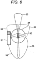
- FIG. 6 illustrates a situation in which the external environment information acquisition unit 2 of the object detection device 1 detects another vehicle and particularly illustrates a situation in which a target vehicle (detected vehicle) crossing a plurality of detection regions with a non-detection region sandwiched therebetween is detected.
- the configuration of the external environment information acquisition unit 2 constituting the object detection device 1 is the same as that of the first embodiment, in which, with the vehicle 30 as the center, the camera 4 is attached to the front of a vehicle 30, a region 35 in front of the vehicle is settled as a detection region of this camera 4, wide angle cameras 4 are attached to the front, rear, left, and right of the vehicle 30, and a region 37 for detecting around 360 degrees of the periphery of the vehicle (a predetermined range thereof) is settled as a detection region of these wide angle cameras 4.
- the radio wave radar 5 is attached to each of the front, rear, left, and right end portions of the vehicle 30 and regions 36 for detecting in a front side area and regions 38 for detecting in a rear side area are settled as detection regions of these radio wave radars 5. For example, when a target vehicle 31 is present on the left side, a front portion of the target vehicle 31 is detected in the detection region 36 of the radio wave radar 5 on the left front side and a rear portion of the target vehicle 31 is detected in the detection region 38 of the radio wave radar 5 on the left rear side.
- the target vehicle 31 is located outside the detection region of the detection region 37 of the wide angle cameras 4 (on the outside of the detection region 37 of the wide angle cameras 4) and an intermediate portion (a portion between the front portion and the rear portion) of the target vehicle 31 is present between the detection region 36 and the detection region 38 of the radio wave radars 5 on the front and rear sides on the outside of the detection region 37 of the wide angle cameras 4. Accordingly, a part (the front portion and the rear portion) of the target vehicle sandwiching the plurality of detection regions is detected and a part (intermediate portion) thereof is not detected.
- FIG. 7 illustrates an example of a detected matter integrated mapping diagram 40 according to the second embodiment of the present invention, in which pieces of information individually detected in a plurality of detection regions (in this example, the detection region 36 and the detection region 38 of the radio wave radars 5) for the target vehicle 31 depicted in FIG. 6 are mapped on coordinates centered on the vehicle 30 by a detected matter integrated mapping unit 11 of a physical value computation unit 7 of a vehicle length determination unit 3.
- this example of a detected matter integrated mapping diagram 40 is expressed by two-dimensional coordinates in longitudinal and lateral directions with a front center portion of the vehicle 30 as the center point.
- Information detected in the detection region 36 of the radio wave radar 5 on the left front side is indicated as a detected target vehicle 32
- information detected in the detection region 38 of the radio wave radar 5 on the left rear side is indicated as a detected target vehicle 33.
- edge portions are indicated as 32a and 33a, respectively.
- This process is a process relating to the entire vehicle recognition process S111 in FIG. 5 by the vehicle length determination unit 3 in the block configuration diagram of the object detection device 1 in FIG. 1 described in the above first embodiment. That is, the process of the flowchart illustrated in FIG. 8 is included in the entire vehicle recognition process S111 and all other processes follow the processes described in the above first embodiment.
- edge information grouping process S121 based on edge information (information on the end portion) on the detected vehicle found out in the front/rear edge recognition process S102 for the detected matter in the above first embodiment, re-grouping is performed between the detected vehicles detected with the non-detection region sandwiched.
- a single vehicle judgment process S122 it is determined whether the information re-grouped in the edge information grouping process S121 represents a single vehicle.
- the re-grouped information represents a single vehicle
- the entire vehicle is recognized, for example, with regard to a detected marker including the information on the front and rear edge portions (end points); then, a distance between coordinates of the front and rear edge portions (end points) is computed in the front-rear-edge-distance computation process S112 and a calculation result thereof is output as the vehicle length of the target vehicle in the vehicle length output process S113, as described in the above first embodiment.
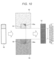
- a region obtained by coupling (grouping) the object presence regions in the respective detection regions in which the end portions are detected and the non-detection region present therebetween is specified or estimated as an object presence region and a length of this object presence region in a predetermined direction (for example, a direction joining both the end portions, the front-rear direction of the vehicle, or a moving direction of the detected object) is determined as the vehicle length of the target vehicle (detailed later on the basis of FIGS. 10 and 11 ).
- a non-detection region length of the non-detection region is added to the detection information (object presence region) on the detection region in a non-detection region length assignment process S123, presuming that the target (vehicle) is present across the non-detection region. That is, when the target is present across the non-detection region, it is presumed that the target is present in the entire non-detection region.
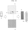
- a region obtained by coupling (grouping) the object presence region in the detection region in which this one end portion is detected and a non-detection region (entire range in a predetermined direction) adjacent to this object presence region is specified or estimated as an object presence region and a length of this object presence region in a predetermined direction (for example, a direction joining both the end portions, the front-rear direction of the vehicle, or a moving direction of the detected object) is determined as the vehicle length of the target vehicle (detailed later on the basis of FIGS. 12 and 13 ).
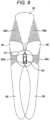
- the non-detection region in which an object cannot be detected by a sensor or the like mounted on the vehicle 30, is settled in advance as an object presence possibility region (39a to 39d) in which an object may be present (refer to FIG. 9 ).
- a region obtained by coupling (grouping) an object presence region obtained by finding out the object in this detection region and a region of the object presence possibility region adjacent to this object presence region in this detection region is specified or estimated as an object presence region in which an object is present or an object may be present (detailed later on the basis of FIGS. 12 and 13 ).
- an arbitrary region of the object presence possibility region (for example, a region having a predetermined length (a general vehicle length or longer) in the front-rear direction on the side of the vehicle) is estimated for the vehicle in advance as an object presence region in which an object may be present (detailed later on the basis of FIGS. 14 and 15 ).
- FIGS. 10 and 11 conceptually illustrate processing patterns in the case of detecting a target vehicle with a non-detection region sandwiched between different detection regions, particularly, processing patterns in the case of detecting a target vehicle (not necessarily the same vehicle) in each of the different detection regions.
- FIG. 10 illustrates the same situation as that in FIG. 6 .
- a part of the target vehicle 50 is detected as a detected marker (an object presence region in the detection region A 53) 55 in the detection region A 53.
- a part of the target vehicle 50 is detected as a detected marker (an object presence region in the detection region B 54) 56 in the detection region B 54.
- the edge information on the detected markers 55 and 56 are noted as 55a and 56a, respectively.
- the detected marker 55 in the detection region A 53 and the detected marker 56 in the detection region B 54 are equivalent to the pattern in FIG. 10 and it is not possible to distinguish the plurality of (two) target vehicles 51a and 51b in reality. Therefore, similarly to the pattern in FIG.
- FIGS. 12 and 13 conceptually illustrate processing patterns in the case of detecting a target vehicle with a non-detection region sandwiched between different detection regions, particularly, processing patterns in the case of detecting a target vehicle in only one detection region.
- a part (front part) of a target vehicle 51 is detected only in the detection region A 53.
- a part (rear part) of the target vehicle 51 is detected only in the detection region B 54.
- object presence possibility region a non-detection region
- FIGS. 14 and 15 conceptually illustrate processing patterns in the case of detecting a target vehicle with a non-detection region sandwiched between different detection regions, particularly, processing patterns in a case where no detected marker (object presence region) is present in adjacent detection regions (detection regions neighboring to each other) sandwiching an undetected region therebetween (in different terms, no detected matter is present in any detection region).
- a detected marker is present in neither the detection region A 53 nor the detection region B 54 and the target vehicle 51 is still not detected in any detection region.
- This situation is equivalent to the state illustrated in FIG. 15 in which no target vehicle is present in the periphery of the vehicle. Therefore, in the situations illustrated in FIGS.
- the non-detection region length (the detected vehicle 52) in this case is settled to be equal to or longer than a general vehicle length.
- the object detection device 1 of the present second embodiment by associating detection results from the external environment information acquisition unit 2 for different detection regions in the surroundings of the vehicle, it is possible to appropriately specify or estimate an object presence region in which an object such as another vehicle in the periphery of the vehicle is present and appropriately calculate the vehicle length and the like of the another vehicle.
- FIGS. 16 and 17 one embodiment of a vehicle control system according to the present invention using one of the above-described object detection devices will be outlined with reference to FIGS. 16 and 17 .
- a situation is supposed here in which, when the vehicle 30 is traveling on a main line and a merging vehicle 71 is merging to the main line from a merging lane at a merging section in the front, a traveling state of the vehicle 30 is controlled (inter-vehicle distance control) by the travel control device.
- the present invention can be similarly applied to a case where the vehicle merges to the main line from the merging lane.
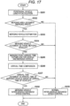
- FIG. 17 illustrates a processing flow of travel control (inter-vehicle distance control) by the vehicle control system according to the present invention.
- a peripheral vehicle length calculation process S201 the vehicle length of a vehicle detected by a sensor of the external environment information acquisition unit 2 mounted on the vehicle is constantly (periodically) calculated using the above-described object detection device.
- a merging area judgment process S202 it is judged from, for example, map information and front camera information whether there is a merging area in front of the vehicle.
- a merging vehicle estimation process S203 determines whether a peripheral vehicle recognized in the peripheral vehicle length calculation process S201 is a merging vehicle in this merging area is estimated from the behavior (bearing, acceleration, traveling history, and the like) of this peripheral vehicle.
- a merging vehicle judgment process S204 whether there is a merging vehicle is judged from an estimation result in the merging vehicle estimation process S203.
- a merging point arrival time estimation process S205 for the vehicle and the merging vehicle the arrival times to the merging point of both of the vehicle and the merging vehicle are estimated from the traveling state and the like of the vehicle and the merging vehicle.
- an arrival time comparison process S206 the arrival times to the merging point estimated in the merging point arrival time estimation process S205 for the vehicle and the merging vehicle are compared between the vehicle and the merging vehicle.
- an arrival time judgment process S207 it is judged which one of the arrival times to the merging point compared in the arrival time comparison process S206 is earlier, in detail, whether the arrival time to the merging point of the merging vehicle is ahead of that of the vehicle.
- a merging vehicle inter-vehicle distance/speed control process S208 inter-vehicle distance control and speed control with respect to the merging vehicle is performed according to the behavior, the vehicle length, and the like of the merging vehicle by the travel control device mounted on the vehicle so as to guide the vehicle behind or in front of the merging vehicle (in other words, the object presence region derived by the object detection device) in the moving direction.
- the normal vehicle travel control is performed when it is judged in the arrival time judgment process S207 that the vehicle first arrives at the merging point.
- speed control and the like of this vehicle may be performed in order to support smooth merging.
- the vehicle control system of the present embodiment by controlling the traveling state of the vehicle based on the object presence region (vehicle length information on another vehicle) specified or estimated by the object detection device, for example, determination on vehicle interrupting (being interrupted) at the time of merging during operation of the automatic driving/driving support system can be accurately judged.
- part or all of the respective configurations, functions, processing units, processing means, and the like described above may be implemented by hardware designed, for example, using an integrated circuit.
- the respective configurations, functions, and the like described above may be implemented by software in which a processor parses a program that implements each of the functions to execute.
- Information such as the programs, the tables, and the files that implement the respective functions can be placed on a storage device including a memory, a hard disk, and a solid state drive (SSD), or alternatively, a recording medium including an integrated circuit (IC) card, an SD card, and a digital versatile disc (DVD).
- IC integrated circuit
- SD Secure Digital versatile disc
- control lines and the information lines considered to be necessary for the description are indicated and therefore, all of the control lines and the information lines on a product are not necessarily indicated. Actually, substantially all of the configurations may be considered to be connected to each other.
Landscapes
- Engineering & Computer Science (AREA)
- Physics & Mathematics (AREA)
- Remote Sensing (AREA)
- Radar, Positioning & Navigation (AREA)
- General Physics & Mathematics (AREA)
- Computer Networks & Wireless Communication (AREA)
- Electromagnetism (AREA)
- Transportation (AREA)
- Mechanical Engineering (AREA)
- Automation & Control Theory (AREA)
- Computer Vision & Pattern Recognition (AREA)
- Theoretical Computer Science (AREA)
- Mathematical Physics (AREA)
- Geometry (AREA)
- Chemical & Material Sciences (AREA)
- Combustion & Propulsion (AREA)
- Traffic Control Systems (AREA)
- Radar Systems Or Details Thereof (AREA)
- Length Measuring Devices By Optical Means (AREA)
Description
- The present invention relates to an object detection device that monitors the periphery of a vehicle and calculates a vehicle length of another vehicle detected in the surroundings of the vehicle; and a vehicle control system including the object detection device.
- In automatic driving/driving support system, when a merging vehicle (for example, another vehicle traveling on a merging lane while the vehicle is traveling on a main line and another vehicle traveling on a main line while the vehicle is traveling on a merging lane) is observed at a merging section, smooth merging is supported while the inter-vehicle distance between the vehicle and a preceding vehicle is controlled.
- Incidentally, in the automatic driving/driving support system, when the vehicle and a merging vehicle are traveling side by side and the total length of the merging vehicle is unknown, there is a risk of danger at the time of merging without merging support (while no actions for merging are taken). Therefore, it is necessary to appropriately find out the total length of another vehicle in the periphery of the vehicle.
- As a conventional technology for finding out an object present in the periphery of the vehicle, for example, an on-vehicle radar device disclosed in following
PTL 1 is known. In this conventional on-vehicle radar device disclosed inPTL 1, the position of an object in the periphery of the vehicle is measured using a radar and the size of another vehicle is found out using a camera that photographs the periphery of the vehicle. Then, in this technology, a grouped region for each position measured for single another vehicle and a grouped region having measurements designated according to the size of the another vehicle are grouped into a group for each equal position, whereby the accuracy of finding out another vehicle in the periphery of the vehicle is improved.PTL 2 describes a vehicle obstacle detecting device which includes at least first and second sensors arranged such that sensing scopes of the first and second sensors do not substantially overlap. The vehicle obstacle detecting device is configured to observe the behavior of an obstacle existing within the sensing scope of one of the first and second sensors and predict the blind spot behavior of the obstacle in a blind spot between the sensing scopes of the first and second sensors based on the observed behavior of the obstacle. -
- PTL 1:
JP 2007-212418 A - PTL 2:
US 2005/012604 A1 - Further,
US-7.142.150-B2 describes to combine laser data and radar data in an occupancy grid. Object boundaries and dimensions are determined. Still further, "360 Degree multi sensor fusion for static and dynamic obstacles" (INTELLIGENT VEHICLES SYMPOSIUM (IV), 2012 IEEE, IEEE, 3 June 2012 (2012-06-03), pages 692-697), describes a vehicle comprising multiple sensors for environment detection and using grid maps for object characterization. Objects are identified by detecting corners. Object dimensions are also determined. - However, even for another vehicle located in a detection region in the periphery of the vehicle, a case where the entire vehicle can be detected within the detection region of a single sensor and a case where another vehicle can be detected by crossing the detection regions of a plurality of sensors are conceivable. In the conventional on-vehicle radar device disclosed in above-mentioned
PTL 1, the same detection region is detected by a plurality of sensors (in this technology, detected by the radar and the camera) and the size such as the vehicle length of another vehicle located in this detection region is found out by a single sensor (camera). Accordingly, consideration is not given to another vehicle in the periphery that is detected across the detection regions of a plurality of sensors. For this reason, it is impossible to appropriately find out the vehicle length or the like of another vehicle that is present across the detection regions of the plurality of sensors. - In addition, in the periphery of the vehicle, there is a non-detection region (a region where an object cannot be detected by a sensor or the like mounted on the vehicle) other than the detection region and it is also conceivable that a part or whole of another vehicle in the periphery of the vehicle is located in this non-detection region. In the conventional technology disclosed in above-mentioned
PTL 1, however, it is not possible to find out the vehicle length or the like of another vehicle present within such a non-detection region. - The present invention has been made in view of the above problems and it is an object of the present invention to provide an object detection device that can appropriately specify, or estimate, the presence region (the vehicle length or the like) of an object, such as another vehicle, that is present in the periphery of a vehicle; and a vehicle control system that includes the object detection device.
- The aforementioned object is solved by the invention according to the independent claims.
- Further preferred developments are described by the dependent claims.
- According to the present invention, by associating detection results for different detection regions in the surroundings of the vehicle, it is possible to appropriately specify or estimate the object presence region in which an object such as another vehicle in the periphery of the vehicle is present. In addition, by controlling the traveling state based on the object presence region (vehicle length information on another vehicle) specified or estimated by the object detection device, for example, determination on vehicle interrupting (being interrupted) at the time of merging during operation of the automatic driving/driving support system can be accurately judged.
- Problems, configurations, and effects other than those mentioned above will be clarified by the description of the following embodiments.
-
- [
FIG. 1] FIG. 1 is a block configuration diagram of a first embodiment of an object detection device according to the present invention. - [
FIG. 2] FIG. 2 is a plan view illustrating an example of a situation of detecting a target vehicle crossing a plurality of detection regions according to the first embodiment of the present invention. - [
FIG. 3] FIG. 3 is an example of a detected matter integrated mapping diagram created by a detected matter integrated mapping unit of a physical value computation unit illustrated inFIG. 1 . - [
FIG. 4] FIG. 4 is an example of a recognized vehicle mapping diagram created by a recognized vehicle mapping unit of a vehicle length computation unit according to the invention. - [
FIG. 5] FIG. 5 is a flowchart illustrating a processing flow by the object detection device illustrated inFIG. 1 . - [
FIG. 6] FIG. 6 is a plan view illustrating another example of a situation of detecting a target vehicle sandwiching a plurality of detection regions according to a second embodiment of the present invention. - [
FIG. 7] FIG. 7 is an example of a detected matter integrated mapping diagram created by a detected matter integrated mapping unit of a physical value computation unit in the second embodiment of the object detection device according to the present invention. - [
FIG. 8] FIG. 8 is a flowchart illustrating a processing flow of an entire vehicle recognition process by the second embodiment of the object detection device according to the present invention. - [
FIG. 9] FIG. 9 is a plan view illustrating an example of an object presence possibility region in the periphery of a vehicle according to the second embodiment of the present invention. - [
FIG. 10] FIG. 10 is a conceptual diagram illustrating a processing pattern (part 1) when a target vehicle is detected with a non-detection region sandwiched according to the second embodiment of the present invention. - [
FIG. 11] FIG. 11 is a conceptual diagram illustrating a processing pattern (part 2) when target vehicles are detected with a non-detection region sandwiched according to the second embodiment of the present invention. - [
FIG. 12] FIG. 12 is a conceptual diagram illustrating a processing pattern (part 3) when a target vehicle is detected with a non-detection region sandwiched according to the second embodiment of the present invention. - [
FIG. 13] FIG. 13 is a conceptual diagram illustrating a processing pattern (part 4) when a target vehicle is detected with a non-detection region sandwiched according to the second embodiment of the present invention. - [
FIG. 14] FIG. 14 is a conceptual diagram illustrating a processing pattern (part 5) when a target vehicle is detected with a non-detection region sandwiched according to the second embodiment of the present invention. - [
FIG. 15] FIG. 15 is a conceptual diagram illustrating a processing pattern (part 6) when a target vehicle is detected with a non-detection region sandwiched according to the second embodiment of the present invention. - [
FIG. 16] FIG. 16 is bird's eye views illustrating situations of travel control by a vehicle control system according to the present invention, where (A) is a diagram illustrating a situation in which another vehicle is merging from the rear side of a vehicle and (B) is a diagram illustrating a situation in which another vehicle is merging from the front side of a vehicle. - [
FIG. 17] FIG. 17 is a flowchart illustrating a processing flow of travel control by the vehicle control system according to the present invention. - Hereinafter, embodiments according to the invention will be described with reference to the drawings.
- First, a first embodiment of an object detection device according to the present invention will be described with reference to
FIGS. 1 to 5 . -
FIG. 1 illustrates a block configuration diagram of an object detection device according to the embodiment of the present invention. - The object detection device of the present embodiment is mounted on a vehicle that travels on a road and is used for accurately specifying or estimating a presence region (object presence region) for an object such as a detected vehicle (another vehicle) in the periphery of the vehicle.
- In the following explanation, the object detection device according to the present embodiment will be described, which calculates the vehicle length of a detected vehicle (another vehicle) in the periphery of a vehicle.
- As illustrated in
FIG. 1 , theobject detection device 1 is constituted mainly by an external environmentinformation acquisition unit 2 and a vehicle length determination unit (object presence region setting unit) 3 included therein. - The external environment
information acquisition unit 2 is used for acquiring external environment information for different detection regions in the surroundings of the vehicle and constituted by acamera 4, aradio wave radar 5, alaser radar 6, and the like. - A stereo camera, a monocular camera, or a charge-coupled device (CCD) camera is used as the
camera 4 and is equipped, for example, in the front of the vehicle, in the rear of the vehicle, and on the sides of the vehicle to image each predetermined range and find out image marker information. - The
radio wave radar 5 is equipped, for example, on the left and right front and rear sides of the vehicle and transmits radio waves to predetermined ranges on the front and rear sides of the vehicle to receive reflected waves from objects on the front and rear sides, thereby finding out the relative position (distance, direction, and size in a horizontal direction) and the relative speed with respect to these objects on the front and rear sides (these pieces of information are referred to as radar marker information). - The
laser radar 6 is equipped, for example, in the left and right front and rear of the vehicle and transmits laser light to predetermined ranges in the periphery of the vehicle to receive reflected light from objects in the periphery of the vehicle, thereby finding out the relative position (distance, direction, and size) and the relative speed with respect to these objects in the periphery of the vehicle (these pieces of information are referred to as radar marker information). In addition, since thelaser radar 6 uses an electromagnetic wave having a wavelength much shorter than that of theradio wave radar 5, thelaser radar 6 is characterized in having a higher three-dimensional size detection accuracy for a detected object but having a shorter detection distance. Therefore, it is possible to adopt a configuration in which thelaser radar 6 is used together with theradio wave radar 5 as a complementary role of theradio wave radar 5, or a configuration in which theradio wave radar 5 is replaced with thelaser radar 6. - Meanwhile, the vehicle length determination unit (object presence region setting unit) 3 is used for specifying or estimating an object presence region in which an object (another vehicle or a detected vehicle) is present or an object (another vehicle or a detected vehicle) may be present in the surroundings of the vehicle to calculate the length (vehicle length) of this object (another vehicle or a detected vehicle) in a front-rear direction. The vehicle length determination unit (object presence region setting unit) 3 is constituted mainly by a physical
value computation unit 7, afusion computation unit 8, and a vehiclelength computation unit 9. - Based on the image marker information by the
camera 4 acquired by the external environmentinformation acquisition unit 2, the physicalvalue computation unit 7 works out the distance and direction with respect to the detected vehicle and the edge (end portion) of the detected vehicle, using a detected matteredge finding unit 10. The edge (end portion) of the detected vehicle is also worked out based on the radar marker information by theradio wave radar 5 or the like. In addition, based on the information acquired by the external environmentinformation acquisition unit 2 and the edge (end portion) of the detected vehicle worked out by the detected matteredge finding unit 10, the physicalvalue computation unit 7 maps the detected vehicle on coordinates centered on the vehicle, using a detected matter integratedmapping unit 11. - Based on the information obtained by the physical
value computation unit 7, thefusion computation unit 8 predicts the trajectory of a vehicle detected for each detection region of the external environmentinformation acquisition unit 2, using atrajectory prediction unit 12 and also determines whether the vehicle detected for each detection region is the same vehicle, using agrouping unit 13. - With respect to a vehicle regarded as the same vehicle by the
fusion computation unit 8, the vehiclelength computation unit 9 maps the same vehicle on the coordinates centered on the vehicle (that is, specifies an object presence region in which the detected vehicle is present on the coordinates centered on the vehicle), using a recognizedvehicle mapping unit 14 and computes the dimensions (vehicle length) between the front and rear edges (end portions) of this same vehicle based on the mapping coordinates, using a vehiclelength calculation unit 15. -
FIG. 2 illustrates a situation in which the external environmentinformation acquisition unit 2 of theobject detection device 1 detects another vehicle in the periphery and particularly illustrates a situation in which a target vehicle (detected vehicle) crossing a plurality of detection regions is detected. - In this embodiment of the invention a
vehicle 30 is mounted with thecamera 4 and theradio wave radar 5. Thecamera 4 is attached to the front of the vehicle and aregion 35 in front of the vehicle is settled as a detection region of thecamera 4. In addition,wide angle cameras 4 are attached to the front, rear, left, and right of thevehicle 30 and aregion 37 for detecting around 360 degrees of the periphery of the vehicle (a predetermined range thereof) is settled as a detection region of thesewide angle cameras 4. Likewise, theradio wave radar 5 is attached to each of the front, rear, left, and right end portions of thevehicle 30 andregions 36 for detecting in a front side area andregions 38 for detecting in a rear side area are settled as detection regions of theseradio wave radars 5. For example, when atarget vehicle 31 is present on the left side, theentire target vehicle 31 is detected in thedetection region 37 of thewide angle cameras 4 and thedetection region 38 of theradio wave radar 5 on the left rear side. -
FIG. 3 illustrates an example of a detected matter integrated mapping diagram 40 according to the first embodiment of the present invention in which pieces of information individually detected in a plurality of detection regions (in this example, thedetection region 37 of thewide angle cameras 4 and thedetection region 38 of the radio wave radar 5) for thetarget vehicle 31 depicted inFIG. 2 are mapped on the coordinates centered on thevehicle 30 by the detected matter integratedmapping unit 11 of the physicalvalue computation unit 7. This example of the detected matter integrated mapping diagram 40 here is expressed by two-dimensional coordinates in longitudinal and lateral directions with a front center portion of thevehicle 30 as the center point. Information detected in thedetection region 37 of the wide angle cameras 4 (in other words, an object presence region of thetarget vehicle 31 in the detection region 37) is indicated as a detectedtarget vehicle 32, whereas information detected in thedetection region 38 of theradio wave radar 5 on the left rear side (in other words, an object presence region of thetarget vehicle 31 in the detection region 38) is indicated as a detectedtarget vehicle 33. In addition, as information on the detectedtarget vehicles detection regions target vehicles -
FIG. 4 illustrates an example of a recognized vehicle mapping diagram 41 according to the first embodiment of the present invention in which the recognizedvehicle mapping unit 14 of the vehiclelength computation unit 9 maps, on the coordinates centered on thevehicle 30, a target vehicle (= object presence region) 34 obtained by grouping the target vehicle detected across the plurality of detection regions illustrated inFIG. 3 as the same vehicle estimated by thefusion computation unit 8, by trajectory prediction according to each detection region. Thistarget vehicle 34 has information on the edge portions (end points) at the front and rear of the vehicle, such that the vehiclelength calculation unit 15 of the vehiclelength computation unit 9 can calculate the vehicle length of the target vehicle 34 (the length of the target vehicle in the front-rear direction or the length of the target vehicle in a direction parallel to the front-rear direction of the vehicle) by computing a distance between coordinates of the respective edge portions (end points) on the coordinates of the recognized vehicle mapping diagram 41. -
FIG. 5 illustrates a processing flow of a series of these processes (processes by the object detection device 1) . - In an image/radar marker information acquisition process S101, detection information (image/radar marker information) for different detection regions in the surroundings of the vehicle is obtained from a plurality of sensors (the
camera 4, theradio wave radar 5, and the like) of the external environmentinformation acquisition unit 2. This image/radar marker information includes measurements, a distance, a relative speed, a bearing, a boundary line, a radio wave strength, and the like of a detected matter in each detection region. - In a front/rear edge recognition process S102 for the detected matter, the edge portion (end point) of the detected matter in each detection region is recognized based on the image/radar marker information acquired in the image/radar marker information acquisition process S101. For example, for the
camera 4, the edge portion of the detected vehicle is recognized by combinations of longitudinal edges and pattern matching of the vehicle based on the captured images. In addition, for theradio wave radar 5, a transmission beam width is narrowed for the detected matter when an object is detected within the detection region and the edge portion is recognized by the radio wave reflection intensity for the detected vehicle (detected matter). - In a common coordinate conversion process S103, range and azimuth (angle) information from the image/radar marker information acquired in the image/radar marker information acquisition process S101 and the position of the edge portion recognized in the front/rear edge recognition process S102 for the detected matter are converted into longitudinal and lateral two-dimensional coordinates with the vehicle as the center point. In an integrated coordinate output process S104, the longitudinal and lateral two-dimensional coordinates converted in the common coordinate conversion process S103 are collectively output as integrated coordinates.
- In a mapping process S105, the detection information from each detection region converted in the common coordinate conversion process S103 and collected as integrated coordinates in the integrated coordinate output process S104 is mapped (refer to the detected matter integrated mapping diagram in
FIG. 3 ). - In a trajectory prediction process S106 for each sensor detected matter, the trajectory of the detected matter in each detection region by the mapping process S105 is estimated based on the history of the accumulated previous image/radar marker information.
- In a grouping process S107, using the detection information from each detection region collected as integrated coordinates in the integrated coordinate output process S104 and information for the detected matter trajectory in each detection region estimated in the trajectory prediction process S106 for each sensor detected matter, clustering and grouping are performed to make estimation as the same vehicle.
- In a coordinate conversion process S108 as the same vehicle, information obtained by estimating markers (detected matters) that have been separately detected in a plurality of detection regions as the same vehicle in the grouping process S107 is converted into longitudinal and lateral two-dimensional coordinates with the vehicle as the center point. In a vehicle coordinate output process S109, the longitudinal and lateral two-dimensional coordinates converted in the coordinate conversion process S108 as the same vehicle are output as vehicle coordinates.
- In a vehicle mapping process S110, the vehicle coordinates converted in the coordinate conversion process S108 as the same vehicle and output in the vehicle coordinate output process S109 are mapped (refer to the recognized vehicle mapping diagram in
FIG. 4 ). - In an entire vehicle recognition process Sill, if a vehicle mapped to the vehicle coordinates in the vehicle mapping process S110 is a continuous marker including the information on the front and rear edge portions (end points), it is assumed that the entire vehicle is recognized.
- In a front-rear-edge-distance computation process S112, a distance between coordinates of the front and rear edge portions (end points) is computed with the coordinates by the vehicle mapping process S110 for the target vehicle, for which the entire vehicle has been recognized in the entire vehicle recognition process S111. In a vehicle length output process S113, a calculation result of the front-rear-edge-distance computation process S112 is output as the vehicle length of the target vehicle.
- Note that the above embodiment has described the case of calculating the vehicle length of another vehicle (detected vehicle) detected across different detection regions. However, of course it is also possible to similarly calculate the vehicle length of a detected vehicle accommodated within a single detection region when detected.
- By repeating a series of these processes, the vehicle length can be calculated for a detected vehicle detected in the periphery of the vehicle.
- As described thus far, according to the
object detection device 1 of the present first embodiment, by associating detection results from the external environmentinformation acquisition unit 2 for different detection regions in the surroundings of the vehicle, it is possible to appropriately specify an object presence region in which an object such as another vehicle detected in the periphery of the vehicle is present and appropriately calculate the vehicle length and the like of the another vehicle. - Next, a second embodiment of the object detection device according to the present invention will be described with reference to
FIGS. 6 to 15 . - The present second embodiment is different from the first embodiment described above in the configuration pertinent to the vehicle
length determination unit 3 in the block configuration diagram of theobject detection device 1 inFIG. 1 , in detail, the configuration pertinent to the entire vehicle recognition process S111 in the processing flow of theobject detection device 1 inFIG. 5 , and the other configurations are approximately the same as those of the first embodiment described above. Therefore, the same reference numerals are given to the same configurations as those of the first embodiment described above and the detailed description thereof will be omitted. Only the differences will be described in detail below. - In the first embodiment described above, in the entire vehicle recognition process S111 in the processing flow in
FIG. 5 , it is assumed that the entire vehicle is recognized if a mapped marker is a continuous marker including the information on the front and rear edge portions (end points) ; then, a distance between coordinates of the front and rear edge portions (end points) is computed in the front-rear-edge-distance computation process S112 and a calculation result thereof is output as the vehicle length in the vehicle length output process S113. - In the present second embodiment, it is supposed that, in the above-described entire vehicle recognition process S111, an object presence region in which an object such as another vehicle is present or an object may be present in the surroundings of the vehicle is specified or estimated and the vehicle length of the another vehicle is estimated and calculated mainly in the following cases.
- (1) A case where the information on the front and rear edge portions (end points) is included and there is an undetected section between the front and rear edge portions (end points) of a discontinuous marker, that is, the detected target vehicle.
- (2) A case where, with regard to a marker having information on only one of the front and rear edge portions (end points), the other edge portion (end point) of the detected target vehicle is present in an area (non-detection region) between multiple detection regions of a plurality of sensors (a
camera 4, aradio wave radar 5, and the like) constituted in an external environmentinformation acquisition unit 2. - (3) A case where the target vehicle is not present (not detected) in any detection region by a plurality of sensors (the
camera 4, theradio wave radar 5, and the like) constituted in the external environmentinformation acquisition unit 2. In other words, a case where the target vehicle is present in a non-detection region between multiple detection regions, or the target vehicle is not present in any detection region or non-detection region. - Note that the block configuration of the
object detection device 1 of the present second embodiment is the same as the block configuration of theobject detection device 1 of the first embodiment described with reference toFIG. 1 . -
FIG. 6 illustrates a situation in which the external environmentinformation acquisition unit 2 of theobject detection device 1 detects another vehicle and particularly illustrates a situation in which a target vehicle (detected vehicle) crossing a plurality of detection regions with a non-detection region sandwiched therebetween is detected. - As described earlier, the configuration of the external environment
information acquisition unit 2 constituting theobject detection device 1 is the same as that of the first embodiment, in which, with thevehicle 30 as the center, thecamera 4 is attached to the front of avehicle 30, aregion 35 in front of the vehicle is settled as a detection region of thiscamera 4,wide angle cameras 4 are attached to the front, rear, left, and right of thevehicle 30, and aregion 37 for detecting around 360 degrees of the periphery of the vehicle (a predetermined range thereof) is settled as a detection region of thesewide angle cameras 4. Likewise, theradio wave radar 5 is attached to each of the front, rear, left, and right end portions of thevehicle 30 andregions 36 for detecting in a front side area andregions 38 for detecting in a rear side area are settled as detection regions of theseradio wave radars 5. For example, when atarget vehicle 31 is present on the left side, a front portion of thetarget vehicle 31 is detected in thedetection region 36 of theradio wave radar 5 on the left front side and a rear portion of thetarget vehicle 31 is detected in thedetection region 38 of theradio wave radar 5 on the left rear side. In this example, thetarget vehicle 31 is located outside the detection region of thedetection region 37 of the wide angle cameras 4 (on the outside of thedetection region 37 of the wide angle cameras 4) and an intermediate portion (a portion between the front portion and the rear portion) of thetarget vehicle 31 is present between thedetection region 36 and thedetection region 38 of theradio wave radars 5 on the front and rear sides on the outside of thedetection region 37 of thewide angle cameras 4. Accordingly, a part (the front portion and the rear portion) of the target vehicle sandwiching the plurality of detection regions is detected and a part (intermediate portion) thereof is not detected. -
FIG. 7 illustrates an example of a detected matter integrated mapping diagram 40 according to the second embodiment of the present invention, in which pieces of information individually detected in a plurality of detection regions (in this example, thedetection region 36 and thedetection region 38 of the radio wave radars 5) for thetarget vehicle 31 depicted inFIG. 6 are mapped on coordinates centered on thevehicle 30 by a detected matter integratedmapping unit 11 of a physicalvalue computation unit 7 of a vehiclelength determination unit 3. As in the case ofFIG. 3 of the first embodiment described above, this example of a detected matter integrated mapping diagram 40 is expressed by two-dimensional coordinates in longitudinal and lateral directions with a front center portion of thevehicle 30 as the center point. Information detected in thedetection region 36 of theradio wave radar 5 on the left front side (in other words, a rectangular object presence region of thetarget vehicle 31 relating to the detection region 36) is indicated as a detectedtarget vehicle 32, whereas information detected in thedetection region 38 of theradio wave radar 5 on the left rear side (in other words, a rectangular object presence region of thetarget vehicle 31 relating to the detection region 38) is indicated as a detectedtarget vehicle 33. In addition, as information on the detectedtarget vehicles detection regions - Note that, in this case, even if the trajectory prediction and the grouping according to each detection region are performed by a fusion computation unit 8 (a
trajectory prediction unit 12 and agrouping unit 13 thereof), there is a high possibility that a deviation has occurred between the detectedtarget vehicles vehicle mapping unit 14 of a vehiclelength computation unit 9. - As described above, in in
FIGS. 6 and7 , only the front portion and the rear portion of thetarget vehicle 31 are detected with the non-detection region sandwiched, as the detectedtarget vehicle 32 and the detectedtarget vehicle 33 that have been mapped. - A process relating to such a case where a target vehicle is detected with the non-detection region sandwiched between the detection regions will be described with reference to a flowchart illustrated in
FIG. 8 . This process is a process relating to the entire vehicle recognition process S111 inFIG. 5 by the vehiclelength determination unit 3 in the block configuration diagram of theobject detection device 1 inFIG. 1 described in the above first embodiment. That is, the process of the flowchart illustrated inFIG. 8 is included in the entire vehicle recognition process S111 and all other processes follow the processes described in the above first embodiment. - In an edge information grouping process S121, based on edge information (information on the end portion) on the detected vehicle found out in the front/rear edge recognition process S102 for the detected matter in the above first embodiment, re-grouping is performed between the detected vehicles detected with the non-detection region sandwiched.
- In a single vehicle judgment process S122, it is determined whether the information re-grouped in the edge information grouping process S121 represents a single vehicle.
- In a case where it is determined in the single vehicle judgment process S122 that the re-grouped information represents a single vehicle, it is assumed that the entire vehicle is recognized, for example, with regard to a detected marker including the information on the front and rear edge portions (end points); then, a distance between coordinates of the front and rear edge portions (end points) is computed in the front-rear-edge-distance computation process S112 and a calculation result thereof is output as the vehicle length of the target vehicle in the vehicle length output process S113, as described in the above first embodiment.
- In other words, when both end portions (not necessarily both end portions of the same object) of the detected marker are detected across a plurality of detection regions with a non-detection region sandwiched therebetween, a region obtained by coupling (grouping) the object presence regions in the respective detection regions in which the end portions are detected and the non-detection region present therebetween is specified or estimated as an object presence region and a length of this object presence region in a predetermined direction (for example, a direction joining both the end portions, the front-rear direction of the vehicle, or a moving direction of the detected object) is determined as the vehicle length of the target vehicle (detailed later on the basis of
FIGS. 10 and11 ). - On the other hand, when it is determined in the single vehicle judgment process S122 that the re-grouped information does not represent a single vehicle, with regard to a detected marker having, for example, information on only one of the front or rear edge portions (end points) and a condition insufficient to be regarded as one vehicle, a non-detection region length of the non-detection region is added to the detection information (object presence region) on the detection region in a non-detection region length assignment process S123, presuming that the target (vehicle) is present across the non-detection region. That is, when the target is present across the non-detection region, it is presumed that the target is present in the entire non-detection region.
- Next, by adding virtual edge (end portion) information for the added portion in a virtual edge information assignment process S124 in consideration of the non-detection region length added in the non-detection region length assignment process S123, it is assumed that the entire vehicle is recognized; then, a distance between coordinates of the front and rear edge portions (end points) is computed in the front-rear-edge-distance computation process S112 and a calculation result thereof is output as the vehicle length of the target vehicle in the vehicle length output process S113, as described in the above embodiment.
- In other words, when one end portion of an object (detected marker) is detected in the detection region and the other end portion of the object (detected marker) is not detected in the detection region, a region obtained by coupling (grouping) the object presence region in the detection region in which this one end portion is detected and a non-detection region (entire range in a predetermined direction) adjacent to this object presence region is specified or estimated as an object presence region and a length of this object presence region in a predetermined direction (for example, a direction joining both the end portions, the front-rear direction of the vehicle, or a moving direction of the detected object) is determined as the vehicle length of the target vehicle (detailed later on the basis of
FIGS. 12 and13 ). - That is, in the present embodiment, in the entire vehicle recognition process S111 in the vehicle
length determination unit 3, the non-detection region in which an object cannot be detected by a sensor or the like mounted on thevehicle 30, such as an area between the respective detection regions in the periphery of thevehicle 30 and a predetermined range from thevehicle 30 on the outside of the respective detection regions, is settled in advance as an object presence possibility region (39a to 39d) in which an object may be present (refer toFIG. 9 ). Then, when a part of an object (target vehicle) is detected in a certain detection region, a region obtained by coupling (grouping) an object presence region obtained by finding out the object in this detection region and a region of the object presence possibility region adjacent to this object presence region in this detection region is specified or estimated as an object presence region in which an object is present or an object may be present (detailed later on the basis ofFIGS. 12 and13 ). In addition, even when an object (target vehicle) is not detected at all in any detection region, an arbitrary region of the object presence possibility region (for example, a region having a predetermined length (a general vehicle length or longer) in the front-rear direction on the side of the vehicle) is estimated for the vehicle in advance as an object presence region in which an object may be present (detailed later on the basis ofFIGS. 14 and15 ). -
FIGS. 10 and11 conceptually illustrate processing patterns in the case of detecting a target vehicle with a non-detection region sandwiched between different detection regions, particularly, processing patterns in the case of detecting a target vehicle (not necessarily the same vehicle) in each of the different detection regions. -
FIG. 10 illustrates the same situation as that inFIG. 6 . - When different
detection region A 53 anddetection region B 54 are disposed (with a non-detection region sandwiched therebetween) and a part of atarget vehicle 50 is detected in each detection region, a part of thetarget vehicle 50 is detected as a detected marker (an object presence region in the detection region A 53) 55 in thedetection region A 53. Likewise, a part of thetarget vehicle 50 is detected as a detected marker (an object presence region in the detection region B 54) 56 in thedetection region B 54. The edge information on the detectedmarkers target vehicle 50 is present also in the non-detection region (= object presence possibility region) sandwiched between the detectedmarker 55 and the detectedmarker 56, the process is carried out by recognizing a region obtained by adding a non-detection region length of the non-detection region to the detectedmarker 55 and the detectedmarker 56 as a detected vehicle (= object presence region) 52. - In addition, in this case, it is also conceivable that, as illustrated in
FIG. 11 , a plurality of (two in the illustrated case)target vehicles - In the
detection region A 53, a part (front part) of thetarget vehicle 51a on the front side is detected. In thedetection region B 54, a part (rear part) of thetarget vehicle 51b on the rear side is detected. At this point, the detectedmarker 55 in thedetection region A 53 and the detectedmarker 56 in thedetection region B 54 are equivalent to the pattern inFIG. 10 and it is not possible to distinguish the plurality of (two)target vehicles FIG. 10 , presuming that thetarget vehicles marker 55 and the detectedmarker 56, the process is carried out by recognizing a region obtained by adding a non-detection region length of the non-detection region to the detectedmarker 55 and the detectedmarker 56 as the detected vehicle (= object presence region) 52. -
FIGS. 12 and13 conceptually illustrate processing patterns in the case of detecting a target vehicle with a non-detection region sandwiched between different detection regions, particularly, processing patterns in the case of detecting a target vehicle in only one detection region. - In the case illustrated in
FIG. 12 , a part (front part) of atarget vehicle 51 is detected only in thedetection region A 53. In thedetection region B 54, a detected matter is not present (not detected) and it can be inferred that the rear edge portion (end point) of thetarget vehicle 51 is located within a non-detection region (= object presence possibility region) between thedetection region A 53 and thedetection region B 54. However, it is not possible to further distinguish which range of this non-detection region is concerned. Therefore, the process is carried out by adding the non-detection region length of the non-detection region adjacent to the detectedmarker 55 in thedetection region A 53 to the detectedmarker 55 in thedetection region A 53 to recognize as the detected vehicle (= object presence region) 52 and at the same time by recognizingvirtual edge information 52b at this detected vehicle 52 (a portion of the non-detection region length thereof). - Likewise, in the case illustrated in
FIG. 13 , a part (rear part) of thetarget vehicle 51 is detected only in thedetection region B 54. In thedetection region A 53, a detected matter is not present (not detected) and it can be inferred that the front edge portion (end point) of thetarget vehicle 51 is located within a non-detection region (= object presence possibility region) between thedetection region A 53 and thedetection region B 54. However, it is not possible to further distinguish which range of this non-detection region is concerned. Therefore, the process is carried out by adding the non-detection region length of the non-detection region adjacent to the detectedmarker 56 in thedetection region B 54 to the detectedmarker 56 in thedetection region B 54 to recognize as the detected vehicle (= object presence region) 52 and at the same time by recognizingvirtual edge information 52a at this detected vehicle 52 (a portion of the non-detection region length thereof). -
FIGS. 14 and15 conceptually illustrate processing patterns in the case of detecting a target vehicle with a non-detection region sandwiched between different detection regions, particularly, processing patterns in a case where no detected marker (object presence region) is present in adjacent detection regions (detection regions neighboring to each other) sandwiching an undetected region therebetween (in different terms, no detected matter is present in any detection region). - In the case illustrated in
FIG. 14 , thetarget vehicle 51 is present only in the non-detection region (= object presence possibility region) in the periphery of the vehicle. In this case, a detected marker is present in neither thedetection region A 53 nor thedetection region B 54 and thetarget vehicle 51 is still not detected in any detection region. This situation is equivalent to the state illustrated inFIG. 15 in which no target vehicle is present in the periphery of the vehicle. Therefore, in the situations illustrated inFIGS. 14 and15 , presuming that a target vehicle is always present within the non-detection region (in particular, within a range of the non-detection region decided in advance for the vehicle), the process is carried out by recognizing a whole non-detection region length of the non-detection region sandwiched by the detection regions as the detected vehicle (= object presence region) 52. However, the non-detection region length (the detected vehicle 52) in this case is settled to be equal to or longer than a general vehicle length. - As described thus far, according to the
object detection device 1 of the present second embodiment, by associating detection results from the external environmentinformation acquisition unit 2 for different detection regions in the surroundings of the vehicle, it is possible to appropriately specify or estimate an object presence region in which an object such as another vehicle in the periphery of the vehicle is present and appropriately calculate the vehicle length and the like of the another vehicle. - Next, one embodiment of a vehicle control system according to the present invention using one of the above-described object detection devices will be outlined with reference to
FIGS. 16 and17 . - As illustrated in
FIGS. 16(A) and 16(B) , a situation is supposed here in which, when thevehicle 30 is traveling on a main line and a mergingvehicle 71 is merging to the main line from a merging lane at a merging section in the front, a traveling state of thevehicle 30 is controlled (inter-vehicle distance control) by the travel control device. However, for example, it goes without saying that the present invention can be similarly applied to a case where the vehicle merges to the main line from the merging lane. - Note that, in the description of the object detection device according to the second embodiment described above, it is presumed that a target vehicle is present in advance in the non-detection region in which an object cannot be detected by a sensor of the external environment
information acquisition unit 2 mounted on thevehicle 30. However, in a merging scene as illustrated inFIGS. 16(A) and 16(B) , such an object (target vehicle) is defined to have both the same bearing and speed as those of thevehicle 30 but solely have a different presence position therefrom and is not regarded as a merging vehicle. - In other words, in a merging scene as illustrated in
FIGS. 16(A) and 16(B) , if the object (target vehicle) presumed to be present in the non-detection region at a certain time is different from thevehicle 30 in speed and bearing, the object after a predetermined time (Δt) will move into the detection region or outside the detection region. In this case, if the object has moved into the detection region, the above-described process of the object detection device of the second embodiment is applied. Otherwise the object is regarded as having moved outside the detection region and will not be regarded as a merging vehicle in a pattern other than the pattern of moving into the detection region. -
FIG. 17 illustrates a processing flow of travel control (inter-vehicle distance control) by the vehicle control system according to the present invention. - In a peripheral vehicle length calculation process S201, the vehicle length of a vehicle detected by a sensor of the external environment
information acquisition unit 2 mounted on the vehicle is constantly (periodically) calculated using the above-described object detection device. - In a merging area judgment process S202, it is judged from, for example, map information and front camera information whether there is a merging area in front of the vehicle.
- When it is judged in the merging area judgment process S202 that there is a merging area, in a merging vehicle estimation process S203, whether a peripheral vehicle recognized in the peripheral vehicle length calculation process S201 is a merging vehicle in this merging area is estimated from the behavior (bearing, acceleration, traveling history, and the like) of this peripheral vehicle.
- In a merging vehicle judgment process S204, whether there is a merging vehicle is judged from an estimation result in the merging vehicle estimation process S203.
- When it is judged in the merging vehicle judgment process S204 that there is a merging vehicle, in a merging point arrival time estimation process S205 for the vehicle and the merging vehicle, the arrival times to the merging point of both of the vehicle and the merging vehicle are estimated from the traveling state and the like of the vehicle and the merging vehicle.
- In an arrival time comparison process S206, the arrival times to the merging point estimated in the merging point arrival time estimation process S205 for the vehicle and the merging vehicle are compared between the vehicle and the merging vehicle.
- In an arrival time judgment process S207, it is judged which one of the arrival times to the merging point compared in the arrival time comparison process S206 is earlier, in detail, whether the arrival time to the merging point of the merging vehicle is ahead of that of the vehicle.
- When it is judged in the arrival time judgment process S207 that the merging vehicle has an earlier arrival time to the merging point, in a merging vehicle inter-vehicle distance/speed control process S208, inter-vehicle distance control and speed control with respect to the merging vehicle is performed according to the behavior, the vehicle length, and the like of the merging vehicle by the travel control device mounted on the vehicle so as to guide the vehicle behind or in front of the merging vehicle (in other words, the object presence region derived by the object detection device) in the moving direction.
- On the other hand, when it is judged in the merging area judgment process S202 that there is no merging area, or it is judged in the merging vehicle judgment process S204 that there is no merging vehicle, or it is judged in the arrival time judgment process S207 that the vehicle first arrives at the merging point, normal vehicle travel control is performed in a normal inter-vehicle distance/speed control process S209.
- Note that, in the above embodiment, the normal vehicle travel control is performed when it is judged in the arrival time judgment process S207 that the vehicle first arrives at the merging point. However, for example, even when it is judged that the vehicle first arrives at the merging point in the arrival time judgment process S207 from the arrival times to the merging point and behavior of the vehicle and the merging vehicle, traffic and road environments in the periphery of the vehicle, and the like, speed control and the like of this vehicle may be performed in order to support smooth merging.
- As described thus far, according to the vehicle control system of the present embodiment, by controlling the traveling state of the vehicle based on the object presence region (vehicle length information on another vehicle) specified or estimated by the object detection device, for example, determination on vehicle interrupting (being interrupted) at the time of merging during operation of the automatic driving/driving support system can be accurately judged.
- Furthermore, part or all of the respective configurations, functions, processing units, processing means, and the like described above may be implemented by hardware designed, for example, using an integrated circuit. The respective configurations, functions, and the like described above may be implemented by software in which a processor parses a program that implements each of the functions to execute. Information such as the programs, the tables, and the files that implement the respective functions can be placed on a storage device including a memory, a hard disk, and a solid state drive (SSD), or alternatively, a recording medium including an integrated circuit (IC) card, an SD card, and a digital versatile disc (DVD).
- Meanwhile, the control lines and the information lines considered to be necessary for the description are indicated and therefore, all of the control lines and the information lines on a product are not necessarily indicated. Actually, substantially all of the configurations may be considered to be connected to each other.
-
- 1
- object detection device
- 2
- external environment information acquisition unit
- 3
- vehicle length determination unit (object presence region setting unit)
- 7
- physical value computation unit
- 8
- fusion computation unit
- 9
- vehicle length computation unit
- 30
- vehicle
- 31
- target vehicle
- 32
- detected matter
- 33
- detected matter
- 34
- target vehicle grouped as same vehicle
- 35
- front camera detection region
- 36
- front side radio wave radar detection region
- 37
- 360-degree wide angle camera detection region
- 38
- rear side radio wave radar detection region
- 39a to 39d
- object presence possibility region
- 50
- target vehicle
- 51
- target vehicle
- 51a
- target vehicle
- 51b
- target vehicle
- 52
- estimated detected vehicle (object presence region)
- 53
- detection region A
- 54
- detection region B
- 55
- detected matter (detected marker) in detection region A
- 56
- detected matter (detected marker) in detection region B
- 71
- merging vehicle
Claims (9)
- An object detection device (1) comprising:an external environment information acquisition unit (2) configured to acquire external environment information for different detection regions (35, 36, 37, 38) in the surroundings of a vehicle (30) using a plurality of sensors (4, 5, 6) mounted on the vehicle (30); andan object presence region setting unit (3) configured toassociate detection results from the external environment information acquisition unit (2) for the different detection regions (35, 36, 37, 38),to specify, or to estimate, object presence regions in which an object is present in the surroundings of the vehicle (30), and to determine a length of another vehicle detected in the surroundings of the vehicle (30), the other vehicle being the object, whereinthe object presence region setting unit (3) is configured to determine the length of the other vehicle (31, 32, 33, 34) byrecognizing a front edge portion(32a) and a rear edge portion(33a) of the other vehicle (31, 32, 33, 34) based on measuring signals of the plurality of sensors (4, 5, 6), wherein the plurality of sensors (4, 5, 6) include a camera (4) attached to the front of the vehicle (30) for detecting a region (35) in front of the vehicle (30), a plurality of wide angle cameras (4) attached to the front, rear, left, and right of the vehicle (30) for detecting a region (37) around 360 degrees of the periphery of the vehicle (30), and a radio wave radar (5) attached to each of the front, rear, left, and right end portions of the vehicle (30) for detecting regions (36, 38) in a front side area and a rear side area of the vehicle (30), whereineach camera (4) is configured to find out image marker information as measuring signals and to recognize an edge portion (32a, 33a) of the detected other vehicle (31, 32, 33, 34) by combinations of longitudinal edges and pattern matching of the other vehicle (31, 32, 33, 34) based on the captured images, andthe radio wave radar (5) is configured to transmit radio waves to the detecting regions (36, 38) in the front side area and the rear side area of the vehicle (30) to receive reflected waves from objects in the detecting regions (36, 38) as a measuring signal, and to find out radar marker information including a relative distance, direction, and size in a horizontal direction and the relative speed with respect to these objects in the detecting regions (36, 38) in the front side area and the rear side area of the vehicle (30),wherein the radio wave radar (5) is configured to recognize an edge portion (32a, 33a) of the detected other vehicle (31, 32, 33, 34) by narrowing a transmission beam when the other vehicle (31, 32, 33, 34) has been detected within the detection regions (36, 38) and determining the radio wave reflection intensity for the detected other vehicle (31, 32, 33, 34), whereinthe object presence region setting unit (3) is configured to indicate image marker information detected in the region (37) around 360 degrees of the periphery of the vehicle (30) as a first detected other vehicle (32) including the front edge portion (32a) in a first detection region (37), and radar marker information detected in the front side area (36) or the rear side area (38) of the vehicle (30) as a second detected other vehicle (33) including the rear edge portion (33a) in a second detection region (38),to map the first and the second detected other vehicle (32, 33) in a coordinate system referenced to the vehicle (30) using range and azimuth angle information from the radar marker information and the front and rear edge portion (32a, 33a) of the image marker information,to group the first and second detected other vehicle (32, 33) detected across the first and second detection region (36, 38) to a single detected other vehicle (34) including the front edge portion (32a) and the rear edge portion (33a) using trajectory prediction according to each detection region;mapping positions of the front edge portion (32a) and the rear edge portion (33a) of the detected other vehicle (31, 32, 33, 34) in a mapping diagram (41) including the coordinate system referenced to the vehicle (30), andcalculating the length of the detected other vehicle (31, 32, 33, 34) based on a distance between coordinates of the front edge portion (32a) and the rear edge portion (33a) of the detected other vehicle (31, 32, 33, 34) in the mapping diagram (41).
- The object detection device (1) according to claim 1, wherein the object presence region setting unit (3) is configured to change a specification or estimation method for the object presence regions on the basis of whether the other vehicle (31, 32, 33, 34) has been detected in each detection region (35, 36, 37, 38).
- The object detection device (1) according to claim 1, wherein, when detecting the other vehicle (31, 32, 33, 34) in at least one of the detection regions (35, 36, 37, 38), the object presence region setting unit (3) is configured to specify or estimate a region of the one of the detection regions (35, 36, 37, 38) including the other vehicle as one of the object presence regions.
- The object detection device (1) according to claim 3, wherein, when the entire other vehicle is detected across a plurality of detection regions (35, 36, 37, 38), the object presence region setting unit (3) is configured to specify or estimate a region obtained by grouping object presence regions in respective detection regions (35, 36, 37, 38) of the plurality of detection regions (35, 36, 37, 38) as one of the object presence regions.
- The object detection device (1) according to claim 1, wherein, when a plurality of end portions of the other vehicle is detected across a plurality of detection regions (35, 36, 37, 38) with a non-detection region sandwiched therebetween, the object presence region setting unit (3) is configured to specify or estimate a region obtained by grouping object presence regions in the respective detection regions (35, 36, 37, 38) in which the end portions have been detected, and the non-detection region present therebetween, as one of the object presence regions, wherein a non-detection region is a region where an object cannot be detected by the plurality of sensors (4, 5, 6) mounted on the vehicle.
- The object detection device (1) according to claim 1, wherein, when one end portion of the other vehicle is detected in one of the detection regions (35, 36, 37, 38) and another end portion of the other vehicle is not detected in the detection regions (35, 36, 37, 38), the object presence region setting unit (3) is configured to specify or estimate a region obtained by grouping an object presence region in the one of the detection regions (35, 36, 37, 38) in which the one end portion has been detected, and a non-detection region adjacent to this object presence region, as one of the object presence regions, wherein a non-detection region is a region where an object cannot be detected by the plurality of sensors (4, 5, 6) mounted on the vehicle.
- A vehicle control system comprising:the object detection device (1) according to claim 1; anda travel control device configured to control a traveling state of the vehicle (30) on the basis of an object presence region specified or estimated by the object detection device (1).
- The vehicle control system according to claim 7, wherein the travel control device is configured to control a traveling state of the vehicle (30) so as to guide the vehicle (30) in front of or behind the object presence region while the vehicle (30) is traveling.
- An object detection method, comprising:acquiring external environment information for different detection regions (35, 36, 37, 38) in the surroundings of a vehicle (30) using a plurality of sensors (4, 5, 6) mounted on the vehicle (30);associating detection results from an external environment information acquisition unit (2) for the different detection regions (35, 36, 37, 38);and determining a length of another vehicle detected in the surroundings of the vehicle (30), wherein the length of the other vehicle is determined byrecognizing a front edge portion (32a) and a rear edge portion (33a) of the other vehicle (31, 32, 33, 34) based on measuring signals of the plurality of sensors (4, 5, 6), wherein the plurality of sensors (4, 5, 6) include a camera (4) attached to the front of the vehicle (30) for detecting a region (35) in front of the vehicle (30), a plurality of wide angle cameras (4) attached to the front, rear, left, and right of the vehicle (30) for detecting a region (37) around 360 degrees of the periphery of the vehicle (30), and a radio wave radar (5) attached to each of the front, rear, left, and right end portions of the vehicle (30) for detecting regions (36, 38) in a front side area and a rear side area of the vehicle (30), whereineach camera (4) is configured to find out image marker information as measuring signals and to recognize an edge portion (32a, 33a) of the detected other vehicle (31, 32, 33, 34) by combinations of longitudinal edges and pattern matching of the other vehicle (31, 32, 33, 34) based on captured images, andthe radio wave radar (5) is configured to transmit radio waves to the detecting regions (36, 38) in the front side area and the rear side area of the vehicle (30) to receive reflected waves from objects in the detecting regions (36, 38) as a measuring signal, and to find out radar marker information including a relative distance, direction, and size in a horizontal direction and the relative speed with respect to these objects in the detecting regions (36, 38) in the front side area and the rear side area of the vehicle (30),wherein the radio wave radar (5) is configured to recognize an edge portion (32a, 33a) of the detected other vehicle (31, 32, 33, 34) by narrowing a transmission beam when the other vehicle (31, 32, 33, 34) has been detected within the detection regions (36, 38) and determining the radio wave reflection intensity for the detected other vehicle (31, 32, 33, 34), whereinimage marker information detected in the region (37) around 360 degrees of the periphery of the vehicle (30) is indicated as a first detected other vehicle (32) including the front edge portion (32a) in a first detection region (37), and radar marker information detected in the front side area (36) or the rear side area (38) of the vehicle (30) is indicated as a second detected other vehicle (33) including the rear edge portion (33a) in a second detection region (38),the first and the second detected other vehicle (32, 33) are mapped in a coordinate system referenced to the vehicle (30) using range and azimuth angle information from the radar marker information and the front and rear edge portion (32a, 33a) of the image marker information,the first and second detected other vehicle (32, 33) detected across the first and second detection region (36, 38) are grouped to a single detected other vehicle (34) including the front edge portion (32a) and the rear edge portion (33a) using trajectory prediction according to each detection region;mapping positions of the front edge portion (32a) and the rear edge portion (33a) of the other vehicle (31, 32, 33, 34) in a mapping diagram (41) including a coordinate system referenced to the vehicle (30), andcalculating the length of the other vehicle (31, 32, 33, 34) based on a distance between coordinates of the front edge portion (32a) and the rear edge portion (33a) of the other vehicle (31, 32, 33, 34) in the mapping diagram (41).
Applications Claiming Priority (2)
| Application Number | Priority Date | Filing Date | Title |
|---|---|---|---|
| JP2016155811 | 2016-08-08 | ||
| PCT/JP2017/026235 WO2018030102A1 (en) | 2016-08-08 | 2017-07-20 | Object detection device and vehicle control system comprising object detection device |
Publications (3)
| Publication Number | Publication Date |
|---|---|
| EP3499483A1 EP3499483A1 (en) | 2019-06-19 |
| EP3499483A4 EP3499483A4 (en) | 2020-04-08 |
| EP3499483B1 true EP3499483B1 (en) | 2024-11-20 |
Family
ID=61162129
Family Applications (1)
| Application Number | Title | Priority Date | Filing Date |
|---|---|---|---|
| EP17839175.1A Active EP3499483B1 (en) | 2016-08-08 | 2017-07-20 | Object detection device and vehicle control system comprising object detection device |
Country Status (4)
| Country | Link |
|---|---|
| US (1) | US20190225266A1 (en) |
| EP (1) | EP3499483B1 (en) |
| JP (1) | JP6694067B2 (en) |
| WO (1) | WO2018030102A1 (en) |
Families Citing this family (10)
| Publication number | Priority date | Publication date | Assignee | Title |
|---|---|---|---|---|
| US10836376B2 (en) * | 2016-09-06 | 2020-11-17 | Magna Electronics Inc. | Vehicle sensing system with enhanced detection of vehicle angle |
| JP6818902B6 (en) * | 2017-09-29 | 2021-03-17 | 日立Astemo株式会社 | Vehicle detection system |
| DE102017223486A1 (en) * | 2017-12-21 | 2019-06-27 | Continental Teves Ag & Co. Ohg | Method and system for avoiding lateral collisions |
| CN110799853B (en) * | 2018-10-26 | 2024-04-30 | 深圳市大疆创新科技有限公司 | Environmental perception system and mobile platform |
| US11899099B2 (en) * | 2018-11-30 | 2024-02-13 | Qualcomm Incorporated | Early fusion of camera and radar frames |
| CN109624972B (en) * | 2018-12-06 | 2020-06-09 | 北京百度网讯科技有限公司 | Method, device and equipment for preventing vehicle from collision and readable storage medium |
| CN111399492A (en) * | 2018-12-28 | 2020-07-10 | 深圳市优必选科技有限公司 | A robot and its obstacle perception method and device |
| JP7307170B2 (en) * | 2019-07-10 | 2023-07-11 | 日立Astemo株式会社 | SENSING PERFORMANCE EVALUATION DIAGNOSTIC SYSTEM OF EXTERNAL WORLD RECOGNIZATION SENSOR AND SENSING PERFORMANCE EVALUATION DIAGNOSTIC METHOD |
| WO2021199651A1 (en) * | 2020-03-31 | 2021-10-07 | パナソニックIpマネジメント株式会社 | Object detection device and driving assistance system |
| CN118284906A (en) * | 2021-12-16 | 2024-07-02 | 古野电气株式会社 | Target monitoring device, target monitoring method and program |
Citations (1)
| Publication number | Priority date | Publication date | Assignee | Title |
|---|---|---|---|---|
| US7142150B2 (en) * | 2004-12-15 | 2006-11-28 | Deere & Company | Method and system for detecting an object using a composite evidence grid |
Family Cites Families (3)
| Publication number | Priority date | Publication date | Assignee | Title |
|---|---|---|---|---|
| JP3985748B2 (en) * | 2003-07-08 | 2007-10-03 | 日産自動車株式会社 | In-vehicle obstacle detection device |
| JP4850531B2 (en) | 2006-02-13 | 2012-01-11 | アルパイン株式会社 | In-vehicle radar system |
| JP5293253B2 (en) * | 2009-02-19 | 2013-09-18 | 日産自動車株式会社 | Ambient object detection apparatus and surrounding object detection method |
-
2017
- 2017-07-20 US US16/313,084 patent/US20190225266A1/en not_active Abandoned
- 2017-07-20 JP JP2018532903A patent/JP6694067B2/en active Active
- 2017-07-20 WO PCT/JP2017/026235 patent/WO2018030102A1/en not_active Ceased
- 2017-07-20 EP EP17839175.1A patent/EP3499483B1/en active Active
Patent Citations (1)
| Publication number | Priority date | Publication date | Assignee | Title |
|---|---|---|---|---|
| US7142150B2 (en) * | 2004-12-15 | 2006-11-28 | Deere & Company | Method and system for detecting an object using a composite evidence grid |
Non-Patent Citations (1)
| Title |
|---|
| KAI SCHUELER ET AL: "360 Degree multi sensor fusion for static and dynamic obstacles", INTELLIGENT VEHICLES SYMPOSIUM (IV), 2012 IEEE, IEEE, 3 June 2012 (2012-06-03), pages 692 - 697, XP032453044, ISBN: 978-1-4673-2119-8, DOI: 10.1109/IVS.2012.6232253 * |
Also Published As
| Publication number | Publication date |
|---|---|
| EP3499483A1 (en) | 2019-06-19 |
| JPWO2018030102A1 (en) | 2019-03-28 |
| EP3499483A4 (en) | 2020-04-08 |
| WO2018030102A1 (en) | 2018-02-15 |
| US20190225266A1 (en) | 2019-07-25 |
| JP6694067B2 (en) | 2020-05-13 |
Similar Documents
| Publication | Publication Date | Title |
|---|---|---|
| EP3499483A1 (en) | Object detection device and vehicle control system comprising object detection device | |
| US20230079730A1 (en) | Control device, scanning system, control method, and program | |
| CN111352110B (en) | Method and device for processing radar data | |
| CN107272001B (en) | External-of-sight obstacle detection and location | |
| JP2019108116A (en) | Device and method for controlling speed of vehicle in longitudinal direction | |
| US20150219761A1 (en) | Collision determination device and collision determination method | |
| US10325163B2 (en) | Vehicle vision | |
| EP2784762A1 (en) | Vehicle identification device | |
| JP6717240B2 (en) | Target detection device | |
| CN110194162B (en) | System and method for detecting an approaching cut-in vehicle based on available spatial signals | |
| CN102696060A (en) | Object detection device and object detection method | |
| JP6413898B2 (en) | Pedestrian determination device | |
| JP7401273B2 (en) | Mobile body control device and method | |
| US11087147B2 (en) | Vehicle lane mapping | |
| US11086007B2 (en) | Target detection device | |
| EP3260878B1 (en) | Moving object detection device, program, and recording medium | |
| JP6834020B2 (en) | Object recognition device and object recognition method | |
| Homm et al. | Fusion of laserscannner and video based lanemarking detection for robust lateral vehicle control and lane change maneuvers | |
| CN110723144A (en) | Lane distribution system | |
| CN112313664A (en) | Method and system for identifying obstacles | |
| JP7344744B2 (en) | Roadside edge detection method and roadside edge detection device | |
| JP6604052B2 (en) | Runway boundary estimation device and runway boundary estimation method | |
| US12548342B2 (en) | External environment recognition device | |
| JP4404633B2 (en) | Method and apparatus for detecting at least one object | |
| EP2720211B1 (en) | Other-vehicle detection device and other-vehicle detection method |
Legal Events
| Date | Code | Title | Description |
|---|---|---|---|
| STAA | Information on the status of an ep patent application or granted ep patent |
Free format text: STATUS: THE INTERNATIONAL PUBLICATION HAS BEEN MADE |
|
| PUAI | Public reference made under article 153(3) epc to a published international application that has entered the european phase |
Free format text: ORIGINAL CODE: 0009012 |
|
| STAA | Information on the status of an ep patent application or granted ep patent |
Free format text: STATUS: REQUEST FOR EXAMINATION WAS MADE |
|
| 17P | Request for examination filed |
Effective date: 20190311 |
|
| AK | Designated contracting states |
Kind code of ref document: A1 Designated state(s): AL AT BE BG CH CY CZ DE DK EE ES FI FR GB GR HR HU IE IS IT LI LT LU LV MC MK MT NL NO PL PT RO RS SE SI SK SM TR |
|
| AX | Request for extension of the european patent |
Extension state: BA ME |
|
| DAV | Request for validation of the european patent (deleted) | ||
| DAX | Request for extension of the european patent (deleted) | ||
| A4 | Supplementary search report drawn up and despatched |
Effective date: 20200305 |
|
| RIC1 | Information provided on ipc code assigned before grant |
Ipc: G08G 1/16 20060101AFI20200228BHEP Ipc: G01S 13/86 20060101ALI20200228BHEP Ipc: G01S 13/93 20200101ALI20200228BHEP Ipc: G01B 21/00 20060101ALI20200228BHEP Ipc: B60W 40/02 20060101ALI20200228BHEP Ipc: B60W 30/16 20200101ALI20200228BHEP |
|
| STAA | Information on the status of an ep patent application or granted ep patent |
Free format text: STATUS: EXAMINATION IS IN PROGRESS |
|
| RAP3 | Party data changed (applicant data changed or rights of an application transferred) |
Owner name: HITACHI ASTEMO, LTD. |
|
| 17Q | First examination report despatched |
Effective date: 20210923 |
|
| RIC1 | Information provided on ipc code assigned before grant |
Ipc: G01S 17/86 20200101ALI20240422BHEP Ipc: G01S 17/931 20200101ALI20240422BHEP Ipc: G01S 17/42 20060101ALI20240422BHEP Ipc: G01S 13/931 20200101ALI20240422BHEP Ipc: B60W 30/08 20120101ALI20240422BHEP Ipc: G01S 17/89 20060101ALI20240422BHEP Ipc: G01S 13/93 20060101ALI20240422BHEP Ipc: G01S 13/86 20060101ALI20240422BHEP Ipc: G01B 21/00 20060101ALI20240422BHEP Ipc: B60W 40/02 20060101ALI20240422BHEP Ipc: B60W 30/16 20120101ALI20240422BHEP Ipc: G08G 1/16 20060101AFI20240422BHEP |
|
| GRAP | Despatch of communication of intention to grant a patent |
Free format text: ORIGINAL CODE: EPIDOSNIGR1 |
|
| GRAP | Despatch of communication of intention to grant a patent |
Free format text: ORIGINAL CODE: EPIDOSNIGR1 |
|
| STAA | Information on the status of an ep patent application or granted ep patent |
Free format text: STATUS: GRANT OF PATENT IS INTENDED |
|
| INTG | Intention to grant announced |
Effective date: 20240614 |
|
| GRAS | Grant fee paid |
Free format text: ORIGINAL CODE: EPIDOSNIGR3 |
|
| GRAA | (expected) grant |
Free format text: ORIGINAL CODE: 0009210 |
|
| STAA | Information on the status of an ep patent application or granted ep patent |
Free format text: STATUS: THE PATENT HAS BEEN GRANTED |
|
| AK | Designated contracting states |
Kind code of ref document: B1 Designated state(s): AL AT BE BG CH CY CZ DE DK EE ES FI FR GB GR HR HU IE IS IT LI LT LU LV MC MK MT NL NO PL PT RO RS SE SI SK SM TR |
|
| REG | Reference to a national code |
Ref country code: GB Ref legal event code: FG4D |
|
| REG | Reference to a national code |
Ref country code: CH Ref legal event code: EP |
|
| REG | Reference to a national code |
Ref country code: DE Ref legal event code: R096 Ref document number: 602017086285 Country of ref document: DE |
|
| REG | Reference to a national code |
Ref country code: IE Ref legal event code: FG4D |
|
| REG | Reference to a national code |
Ref country code: LT Ref legal event code: MG9D |
|
| REG | Reference to a national code |
Ref country code: NL Ref legal event code: MP Effective date: 20241120 |
|
| PG25 | Lapsed in a contracting state [announced via postgrant information from national office to epo] |
Ref country code: HR Free format text: LAPSE BECAUSE OF FAILURE TO SUBMIT A TRANSLATION OF THE DESCRIPTION OR TO PAY THE FEE WITHIN THE PRESCRIBED TIME-LIMIT Effective date: 20241120 Ref country code: PT Free format text: LAPSE BECAUSE OF FAILURE TO SUBMIT A TRANSLATION OF THE DESCRIPTION OR TO PAY THE FEE WITHIN THE PRESCRIBED TIME-LIMIT Effective date: 20250320 Ref country code: IS Free format text: LAPSE BECAUSE OF FAILURE TO SUBMIT A TRANSLATION OF THE DESCRIPTION OR TO PAY THE FEE WITHIN THE PRESCRIBED TIME-LIMIT Effective date: 20250320 |
|
| PG25 | Lapsed in a contracting state [announced via postgrant information from national office to epo] |
Ref country code: FI Free format text: LAPSE BECAUSE OF FAILURE TO SUBMIT A TRANSLATION OF THE DESCRIPTION OR TO PAY THE FEE WITHIN THE PRESCRIBED TIME-LIMIT Effective date: 20241120 Ref country code: NL Free format text: LAPSE BECAUSE OF FAILURE TO SUBMIT A TRANSLATION OF THE DESCRIPTION OR TO PAY THE FEE WITHIN THE PRESCRIBED TIME-LIMIT Effective date: 20241120 |
|
| REG | Reference to a national code |
Ref country code: AT Ref legal event code: MK05 Ref document number: 1744314 Country of ref document: AT Kind code of ref document: T Effective date: 20241120 |
|
| PG25 | Lapsed in a contracting state [announced via postgrant information from national office to epo] |
Ref country code: BG Free format text: LAPSE BECAUSE OF FAILURE TO SUBMIT A TRANSLATION OF THE DESCRIPTION OR TO PAY THE FEE WITHIN THE PRESCRIBED TIME-LIMIT Effective date: 20241120 |
|
| PG25 | Lapsed in a contracting state [announced via postgrant information from national office to epo] |
Ref country code: ES Free format text: LAPSE BECAUSE OF FAILURE TO SUBMIT A TRANSLATION OF THE DESCRIPTION OR TO PAY THE FEE WITHIN THE PRESCRIBED TIME-LIMIT Effective date: 20241120 |
|
| PG25 | Lapsed in a contracting state [announced via postgrant information from national office to epo] |
Ref country code: NO Free format text: LAPSE BECAUSE OF FAILURE TO SUBMIT A TRANSLATION OF THE DESCRIPTION OR TO PAY THE FEE WITHIN THE PRESCRIBED TIME-LIMIT Effective date: 20250220 |
|
| PG25 | Lapsed in a contracting state [announced via postgrant information from national office to epo] |
Ref country code: LV Free format text: LAPSE BECAUSE OF FAILURE TO SUBMIT A TRANSLATION OF THE DESCRIPTION OR TO PAY THE FEE WITHIN THE PRESCRIBED TIME-LIMIT Effective date: 20241120 Ref country code: AT Free format text: LAPSE BECAUSE OF FAILURE TO SUBMIT A TRANSLATION OF THE DESCRIPTION OR TO PAY THE FEE WITHIN THE PRESCRIBED TIME-LIMIT Effective date: 20241120 Ref country code: GR Free format text: LAPSE BECAUSE OF FAILURE TO SUBMIT A TRANSLATION OF THE DESCRIPTION OR TO PAY THE FEE WITHIN THE PRESCRIBED TIME-LIMIT Effective date: 20250221 |
|
| PG25 | Lapsed in a contracting state [announced via postgrant information from national office to epo] |
Ref country code: PL Free format text: LAPSE BECAUSE OF FAILURE TO SUBMIT A TRANSLATION OF THE DESCRIPTION OR TO PAY THE FEE WITHIN THE PRESCRIBED TIME-LIMIT Effective date: 20241120 |
|
| PG25 | Lapsed in a contracting state [announced via postgrant information from national office to epo] |
Ref country code: RS Free format text: LAPSE BECAUSE OF FAILURE TO SUBMIT A TRANSLATION OF THE DESCRIPTION OR TO PAY THE FEE WITHIN THE PRESCRIBED TIME-LIMIT Effective date: 20250220 |
|
| PG25 | Lapsed in a contracting state [announced via postgrant information from national office to epo] |
Ref country code: SM Free format text: LAPSE BECAUSE OF FAILURE TO SUBMIT A TRANSLATION OF THE DESCRIPTION OR TO PAY THE FEE WITHIN THE PRESCRIBED TIME-LIMIT Effective date: 20241120 |
|
| PG25 | Lapsed in a contracting state [announced via postgrant information from national office to epo] |
Ref country code: DK Free format text: LAPSE BECAUSE OF FAILURE TO SUBMIT A TRANSLATION OF THE DESCRIPTION OR TO PAY THE FEE WITHIN THE PRESCRIBED TIME-LIMIT Effective date: 20241120 |
|
| PG25 | Lapsed in a contracting state [announced via postgrant information from national office to epo] |
Ref country code: EE Free format text: LAPSE BECAUSE OF FAILURE TO SUBMIT A TRANSLATION OF THE DESCRIPTION OR TO PAY THE FEE WITHIN THE PRESCRIBED TIME-LIMIT Effective date: 20241120 |
|
| PGFP | Annual fee paid to national office [announced via postgrant information from national office to epo] |
Ref country code: FR Payment date: 20250610 Year of fee payment: 9 |
|
| PG25 | Lapsed in a contracting state [announced via postgrant information from national office to epo] |
Ref country code: RO Free format text: LAPSE BECAUSE OF FAILURE TO SUBMIT A TRANSLATION OF THE DESCRIPTION OR TO PAY THE FEE WITHIN THE PRESCRIBED TIME-LIMIT Effective date: 20241120 |
|
| PG25 | Lapsed in a contracting state [announced via postgrant information from national office to epo] |
Ref country code: SK Free format text: LAPSE BECAUSE OF FAILURE TO SUBMIT A TRANSLATION OF THE DESCRIPTION OR TO PAY THE FEE WITHIN THE PRESCRIBED TIME-LIMIT Effective date: 20241120 |
|
| PG25 | Lapsed in a contracting state [announced via postgrant information from national office to epo] |
Ref country code: CZ Free format text: LAPSE BECAUSE OF FAILURE TO SUBMIT A TRANSLATION OF THE DESCRIPTION OR TO PAY THE FEE WITHIN THE PRESCRIBED TIME-LIMIT Effective date: 20241120 |
|
| PG25 | Lapsed in a contracting state [announced via postgrant information from national office to epo] |
Ref country code: IT Free format text: LAPSE BECAUSE OF FAILURE TO SUBMIT A TRANSLATION OF THE DESCRIPTION OR TO PAY THE FEE WITHIN THE PRESCRIBED TIME-LIMIT Effective date: 20241120 |
|
| REG | Reference to a national code |
Ref country code: DE Ref legal event code: R097 Ref document number: 602017086285 Country of ref document: DE |
|
| PG25 | Lapsed in a contracting state [announced via postgrant information from national office to epo] |
Ref country code: SE Free format text: LAPSE BECAUSE OF FAILURE TO SUBMIT A TRANSLATION OF THE DESCRIPTION OR TO PAY THE FEE WITHIN THE PRESCRIBED TIME-LIMIT Effective date: 20241120 |
|
| PLBE | No opposition filed within time limit |
Free format text: ORIGINAL CODE: 0009261 |
|
| STAA | Information on the status of an ep patent application or granted ep patent |
Free format text: STATUS: NO OPPOSITION FILED WITHIN TIME LIMIT |
|
| PGFP | Annual fee paid to national office [announced via postgrant information from national office to epo] |
Ref country code: DE Payment date: 20250528 Year of fee payment: 9 |
|
| 26N | No opposition filed |
Effective date: 20250821 |
|
| REG | Reference to a national code |
Ref country code: CH Ref legal event code: H13 Free format text: ST27 STATUS EVENT CODE: U-0-0-H10-H13 (AS PROVIDED BY THE NATIONAL OFFICE) Effective date: 20260224 |
|
| PG25 | Lapsed in a contracting state [announced via postgrant information from national office to epo] |
Ref country code: LU Free format text: LAPSE BECAUSE OF NON-PAYMENT OF DUE FEES Effective date: 20250720 |
|
| GBPC | Gb: european patent ceased through non-payment of renewal fee |
Effective date: 20250720 |
|
| REG | Reference to a national code |
Ref country code: BE Ref legal event code: MM Effective date: 20250731 |
|
| PG25 | Lapsed in a contracting state [announced via postgrant information from national office to epo] |
Ref country code: GB Free format text: LAPSE BECAUSE OF NON-PAYMENT OF DUE FEES Effective date: 20250720 |
|
| PG25 | Lapsed in a contracting state [announced via postgrant information from national office to epo] |
Ref country code: BE Free format text: LAPSE BECAUSE OF NON-PAYMENT OF DUE FEES Effective date: 20250731 |
|
| PG25 | Lapsed in a contracting state [announced via postgrant information from national office to epo] |
Ref country code: CH Free format text: LAPSE BECAUSE OF NON-PAYMENT OF DUE FEES Effective date: 20250731 |