EP3499313A1 - Power supply lock structure and image forming apparatus - Google Patents
Power supply lock structure and image forming apparatus Download PDFInfo
- Publication number
- EP3499313A1 EP3499313A1 EP18212989.0A EP18212989A EP3499313A1 EP 3499313 A1 EP3499313 A1 EP 3499313A1 EP 18212989 A EP18212989 A EP 18212989A EP 3499313 A1 EP3499313 A1 EP 3499313A1
- Authority
- EP
- European Patent Office
- Prior art keywords
- posture
- power supply
- locking mechanism
- cover
- image forming
- Prior art date
- Legal status (The legal status is an assumption and is not a legal conclusion. Google has not performed a legal analysis and makes no representation as to the accuracy of the status listed.)
- Granted
Links
Images






Classifications
-
- G—PHYSICS
- G03—PHOTOGRAPHY; CINEMATOGRAPHY; ANALOGOUS TECHNIQUES USING WAVES OTHER THAN OPTICAL WAVES; ELECTROGRAPHY; HOLOGRAPHY
- G03G—ELECTROGRAPHY; ELECTROPHOTOGRAPHY; MAGNETOGRAPHY
- G03G15/00—Apparatus for electrographic processes using a charge pattern
- G03G15/50—Machine control of apparatus for electrographic processes using a charge pattern, e.g. regulating differents parts of the machine, multimode copiers, microprocessor control
- G03G15/5004—Power supply control, e.g. power-saving mode, automatic power turn-off
-
- G—PHYSICS
- G03—PHOTOGRAPHY; CINEMATOGRAPHY; ANALOGOUS TECHNIQUES USING WAVES OTHER THAN OPTICAL WAVES; ELECTROGRAPHY; HOLOGRAPHY
- G03G—ELECTROGRAPHY; ELECTROPHOTOGRAPHY; MAGNETOGRAPHY
- G03G15/00—Apparatus for electrographic processes using a charge pattern
- G03G15/06—Apparatus for electrographic processes using a charge pattern for developing
- G03G15/08—Apparatus for electrographic processes using a charge pattern for developing using a solid developer, e.g. powder developer
- G03G15/0822—Arrangements for preparing, mixing, supplying or dispensing developer
- G03G15/0865—Arrangements for supplying new developer
-
- G—PHYSICS
- G03—PHOTOGRAPHY; CINEMATOGRAPHY; ANALOGOUS TECHNIQUES USING WAVES OTHER THAN OPTICAL WAVES; ELECTROGRAPHY; HOLOGRAPHY
- G03G—ELECTROGRAPHY; ELECTROPHOTOGRAPHY; MAGNETOGRAPHY
- G03G15/00—Apparatus for electrographic processes using a charge pattern
- G03G15/50—Machine control of apparatus for electrographic processes using a charge pattern, e.g. regulating differents parts of the machine, multimode copiers, microprocessor control
- G03G15/5016—User-machine interface; Display panels; Control console
-
- G—PHYSICS
- G03—PHOTOGRAPHY; CINEMATOGRAPHY; ANALOGOUS TECHNIQUES USING WAVES OTHER THAN OPTICAL WAVES; ELECTROGRAPHY; HOLOGRAPHY
- G03G—ELECTROGRAPHY; ELECTROPHOTOGRAPHY; MAGNETOGRAPHY
- G03G15/00—Apparatus for electrographic processes using a charge pattern
- G03G15/80—Details relating to power supplies, circuits boards, electrical connections
-
- G—PHYSICS
- G03—PHOTOGRAPHY; CINEMATOGRAPHY; ANALOGOUS TECHNIQUES USING WAVES OTHER THAN OPTICAL WAVES; ELECTROGRAPHY; HOLOGRAPHY
- G03G—ELECTROGRAPHY; ELECTROPHOTOGRAPHY; MAGNETOGRAPHY
- G03G21/00—Arrangements not provided for by groups G03G13/00 - G03G19/00, e.g. cleaning, elimination of residual charge
- G03G21/16—Mechanical means for facilitating the maintenance of the apparatus, e.g. modular arrangements
- G03G21/1604—Arrangement or disposition of the entire apparatus
- G03G21/1623—Means to access the interior of the apparatus
- G03G21/1633—Means to access the interior of the apparatus using doors or covers
-
- G—PHYSICS
- G03—PHOTOGRAPHY; CINEMATOGRAPHY; ANALOGOUS TECHNIQUES USING WAVES OTHER THAN OPTICAL WAVES; ELECTROGRAPHY; HOLOGRAPHY
- G03G—ELECTROGRAPHY; ELECTROPHOTOGRAPHY; MAGNETOGRAPHY
- G03G21/00—Arrangements not provided for by groups G03G13/00 - G03G19/00, e.g. cleaning, elimination of residual charge
- G03G21/16—Mechanical means for facilitating the maintenance of the apparatus, e.g. modular arrangements
- G03G21/1661—Mechanical means for facilitating the maintenance of the apparatus, e.g. modular arrangements means for handling parts of the apparatus in the apparatus
- G03G21/1676—Mechanical means for facilitating the maintenance of the apparatus, e.g. modular arrangements means for handling parts of the apparatus in the apparatus for the developer unit
-
- G—PHYSICS
- G03—PHOTOGRAPHY; CINEMATOGRAPHY; ANALOGOUS TECHNIQUES USING WAVES OTHER THAN OPTICAL WAVES; ELECTROGRAPHY; HOLOGRAPHY
- G03G—ELECTROGRAPHY; ELECTROPHOTOGRAPHY; MAGNETOGRAPHY
- G03G21/00—Arrangements not provided for by groups G03G13/00 - G03G19/00, e.g. cleaning, elimination of residual charge
- G03G21/16—Mechanical means for facilitating the maintenance of the apparatus, e.g. modular arrangements
- G03G21/18—Mechanical means for facilitating the maintenance of the apparatus, e.g. modular arrangements using a processing cartridge, whereby the process cartridge comprises at least two image processing means in a single unit
- G03G21/1803—Arrangements or disposition of the complete process cartridge or parts thereof
- G03G21/181—Manufacturing or assembling, recycling, reuse, transportation, packaging or storage
-
- G—PHYSICS
- G03—PHOTOGRAPHY; CINEMATOGRAPHY; ANALOGOUS TECHNIQUES USING WAVES OTHER THAN OPTICAL WAVES; ELECTROGRAPHY; HOLOGRAPHY
- G03G—ELECTROGRAPHY; ELECTROPHOTOGRAPHY; MAGNETOGRAPHY
- G03G21/00—Arrangements not provided for by groups G03G13/00 - G03G19/00, e.g. cleaning, elimination of residual charge
- G03G21/16—Mechanical means for facilitating the maintenance of the apparatus, e.g. modular arrangements
- G03G21/18—Mechanical means for facilitating the maintenance of the apparatus, e.g. modular arrangements using a processing cartridge, whereby the process cartridge comprises at least two image processing means in a single unit
- G03G21/1803—Arrangements or disposition of the complete process cartridge or parts thereof
- G03G21/1817—Arrangements or disposition of the complete process cartridge or parts thereof having a submodular arrangement
- G03G21/1821—Arrangements or disposition of the complete process cartridge or parts thereof having a submodular arrangement means for connecting the different parts of the process cartridge, e.g. attachment, positioning of parts with each other, pressure/distance regulation
Definitions
- the present disclosure relates to a power supply lock structure and an image forming apparatus.
- An example of an image forming apparatus includes a casing, a development device, and a toner container.
- the casing includes a front cover.
- the development device includes a toner replenishment port.
- the standby position is a position in which the development device has been rotated in a first direction from a development position around a first axis that is parallel to a rotary shaft of a photosensitive drum.
- the toner container is detachable from the casing through the insertion path after rotating in a second direction around a second axis.
- the second axis is parallel to the first axis.
- the second direction is opposite to the first direction.
- the development device and the toner container can be easily detached from the casing.
- the image forming apparatus When being manufactured and transported, the image forming apparatus is arranged in a posture in which toner is not supplied from the toner container. Therefore, a user must open a cover and change the posture of the toner container so that toner can be supplied from the toner container.
- operating instructions describing operation steps for the user to put the transported image forming apparatus into a usable state are affixed to the image forming apparatus.
- a power supply lock structure includes a power button and a locking mechanism.
- the power button switches a power supply between on and off.
- the locking mechanism prohibits operation of the power button.
- the locking mechanism is located on a cover. Prohibition of the operation of the power supply is releasable by the locking mechanism only when the cover is open.
- An image forming apparatus includes a power supply lock structure, an image forming section, and a casing.
- the image forming section forms an image on a recording medium.
- the casing includes a cover and houses the image forming section.
- the power supply lock structure includes a power button and a locking mechanism.
- the power button switches a power supply between on and off.
- the locking mechanism prohibits operation of the power supply by the power button.
- the locking mechanism is located on the cover. Prohibition of the operation of the power supply is releasable by the locking mechanism only when the cover is open.
- FIGS. 1 to 17B an embodiment of the present disclosure is described with reference to the accompanying drawings ( FIGS. 1 to 17B ). Note that elements that are the same or equivalent are labelled with the same reference signs in the drawings and description thereof is not repeated.
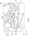
- FIG. 1 is a diagram illustrating a configuration of the image forming apparatus 100. As illustrated in FIG. 1 , the image forming apparatus 100 is a printer.
- FIG. 1 Mutually orthogonal X, Y, and Z axes are shown in FIG. 1 .
- the X and Y axes are parallel to a horizontal plane.
- the Z axis is parallel to a vertical direction.
- a positive X axis direction may be considered backward, and a negative X axis direction may be considered forward.
- the image forming apparatus 100 includes a casing 10, a feeding section 12, a conveyance section L, a toner supply section 13, an image forming section 14, a fixing section 16, an ejection roller pair 17, and an exit tray 18.
- the casing 10 houses the feeding section 12, the conveyance section L, the toner supply section 13, the image forming section 14, the fixing section 16, and the ejection roller pair 17.
- the feeding section 12 feeds paper P to the conveyance section L.
- the conveyance section L conveys the paper P to the ejection roller pair 17 by way of the image forming section 14 and the fixing section 16.
- a toner container TC is attached to the toner supply section 13.
- the toner container TC supplies toner to the image forming section 14.
- the image forming section 14 includes a photosensitive drum 141, a charger 142, a light exposure section 143, a development section 145, a transfer roller 146, and a cleaning section 147.
- the charger 142 charges the photosensitive drum 141 to a predetermined potential.
- the light exposure section 143 radiates laser light to expose the photosensitive drum 141 to the laser light, thus forming an electrostatic latent image on the photosensitive drum 141.
- the development section 145 supplies toner to the photosensitive drum 141, thus developing the electrostatic latent image into a toner image. In this manner, a toner image is formed on a peripheral surface of the photosensitive drum 141.
- the transfer roller 146 transfers the toner image from the photosensitive drum 141 to the paper P. As a result, an image is formed on the paper P.
- the cleaning section 147 removes remaining toner from the peripheral surface of the photosensitive drum 141.
- the paper P with the image formed thereon is conveyed to the fixing section 16.
- the fixing section 16 applies heat and pressure to the paper P, thus fixing the image formed on the paper P to the paper P.
- the paper P with the image fixed thereon is ejected to the exit tray 18 by the ejection roller pair 17.
- the casing 10 includes a front cover 101.
- the front cover 101 is open in attachment and detachment of the toner container TC.
- the front cover 101 includes a cover main body 101A and a support shaft 101B.
- the support shaft 101B is a cylindrical member extending in a Y axis direction.
- the support shaft 101B rotatably supports the cover main body 101A.
- the cover main body 101A is flatly plate-shaped and is configured to rotate in a direction D1 as indicated by an arrow D1 about the support shaft 101B serving as a fulcrum thereof.
- the front cover 101 is equivalent to an example of a "cover".
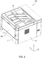
- FIG. 2 is a perspective view illustrating the configuration of the image forming apparatus 100. As illustrated in FIG. 2 , the image forming apparatus 100 further includes a power supply lock structure 2. The power supply lock structure 2 is located on an end of the front cover 101 in a negative Y axis direction.
- FIG. 3 is a perspective view illustrating the arrangement of the power supply lock structure 2.
- the front cover 101 is open.
- the power supply lock structure 2 is located on a back surface of the front cover 101.
- FIG. 4 is an exploded perspective view illustrating the configuration of the power supply lock structure 2.
- the power supply lock structure 2 includes a power button 21 and a locking mechanism 20.
- the locking mechanism 20 includes a supporting member 22 and a rotary member 23.
- the power button 21 has a button 211 and a shaft member 212.
- the button 211 is disk-shaped and is pressed by a user when power is switched on or off.
- the button 211 is exposed on a front surface of the front cover 101. That is, the user can press the button 211 to switch a power supply between on and off when the front cover 101 is closed.
- the front surface faces in the negative X axis direction and is equivalent to an "obverse surface".
- the shaft member 212 supports the button 211.
- the shaft member 212 extends in an X axis direction. That is, an axial direction of the shaft member 212 is parallel to the X axis.
- a cross section of the shaft member 212 in a direction perpendicular to the axial direction of the shaft member 212 is cross-shaped.
- the direction perpendicular to the axial direction of the shaft member 212 is a direction parallel to a Y-Z plane.
- the shaft member 212 is inserted through the supporting member 22 and the rotary member 23.
- the shaft member 212 has a stepped portion 213.
- the shaft member 212 is tapered in the positive X axis direction. That is, in the stepped portion 213, a size of the cross section in a direction perpendicular to the axial direction of the shaft member 212 decreases in steps in the positive X axis direction.
- the stepped portion 213 is in contact with the rotary member 23.
- the locking mechanism 20 prohibits movement of the shaft member 212 in the axial direction of the shaft member 212.
- the locking mechanism 20 is located on the back surface of the front cover 101. Therefore, the locking mechanism 20 can release prohibition of operation of the power supply only when the front cover 101 is open.
- the back surface faces in the positive X axis direction and is equivalent to a "reverse surface".
- the supporting member 22 is secured to the front cover 101 and rotatably supports the rotary member 23.
- the supporting member 22 includes a base member 221, a first guide member 222, and a second guide member 224.
- the base member 221 is rectangular plate-shaped.
- the base member 221 has a lock displaying section MC, an unlock displaying section MP, and an insertion hole 225.
- the lock displaying section MC and the unlock displaying section MP are located on a back surface of the base member 221.
- a mark of a locked padlock is displayed on the lock displaying section MC.
- a mark of an unlocked padlock is displayed on the unlock displaying section MP.
- the insertion hole 225 is a round hole formed in a central portion of the base member 221.
- the shaft member 212 is inserted through the insertion hole 225.
- the first guide member 222 is a hollow rectangular prism-shaped member erected on the base member 221 in the positive X axis direction. A portion of the rotary member 23 is inserted into the first guide member 222.
- the first guide member 222 includes four protruding members 223. Each of the four protruding members 223 is a plate-shaped member erected inward on an end of the first guide member 222 in the positive X axis direction.
- the four protruding members 223 include a first protruding member 223A, a second protruding member 223B, a third protruding member 223C, and a fourth protruding member 223D.
- the first protruding member 223A is located on a side of the first guide member 222 in a positive Z axis direction.
- the second protruding member 223B is located on a side of the first guide member 222 in a negative Z axis direction.
- the third protruding member 223C is located on a side of the first guide member 222 in the negative Y axis direction.
- the fourth protruding member 223D is located on a side of the first guide member 222 in a positive Y axis direction.
- the first protruding member 223A and the second protruding member 223B are located opposite to each other.
- the third protruding member 223C and the fourth protruding member 223D are located opposite to each other.
- the second guide member 224 is a cylindrical member erected on the base member 221 in the positive X axis direction.
- the second guide member 224 is located between the insertion hole 225 and the first guide member 222.
- a portion of the rotary member 23 is inserted between the second guide member 224 and the first guide member 222.
- the rotary member 23 is cylindrical and is rotatably supported by the supporting member 22. Specifically, an end of the rotary member 23 in the negative X axis direction is in contact with a surface of the base member 221 of the supporting member 22 in the positive X axis direction.
- the rotary member 23 includes a grip section 231, four engaging members 232, and an indicating member 234.
- the grip section 231 has a plurality of grooves on a side of the rotary member 23 in the positive X axis direction. Specifically, each of the grooves composing the grip section 231 linearly extends in the X axis direction in an outer peripheral surface of the rotary member 23. The grip section 231 is gripped by the user rotating the rotary member 23.
- Each of the four engaging members 232 is a rectangular plate-shaped member erected on the end of the rotary member 23 in the negative X axis direction. Each of the four engaging members 232 is erected outward on the outer peripheral surface of the rotary member 23. That is, each of the four engaging members 232 is erected in a direction away from a central axis of the rotary member 23.
- the four engaging members 232 include a first engaging member 232A, a second engaging member 232B, a third engaging member 232C, and a fourth engaging member 232D.
- the first engaging member 232A engages with the first protruding member 223A.
- the second engaging member 232B engages with the second protruding member 223B.
- the third engaging member 232C engages with the third protruding member 223C.
- the fourth engaging member 232D engages with the fourth protruding member 223D.
- the fourth engaging member 232D engages with the fourth protruding member 223D. That is, the four engaging members 232 respectively engage with the four protruding members 223 at the same time. The four engaging members 232 also respectively release engagement from the four protruding members 223 at the same time.
- the four engaging members 232 engaging with the respective four protruding members 223 may be simply referred to as “the engaging members 232 engaging with the protruding members 223".
- the four engaging members 232 releasing from engagement with the respective four protruding members 223 may be simply referred to as "the engaging members 232 being released from engagement with the protruding members 223".
- Movement of the shaft member 212 in the axial direction of the shaft member 212 is prohibited by the engaging members 232 engaging with the protruding members 223, thus prohibiting operation of the power button 21. Also, prohibition of movement of the shaft member 212 in the axial direction of the shaft member 212 is released by the engaging members 232 being released from engagement with the protruding members 223, thus releasing prohibition of the operation of the power button 21.
- the indicating member 234 indicates whether the rotary member 23 is in the first rotational position or the second rotational position.
- the indicating member 234 is a triangular plate-shaped member erected on a central portion of the rotary member 23 in the X axis direction.
- the indicating member 234 indicates that the rotary member 23 is in the first rotational position.
- the indicating member 234 indicates that the rotary member 23 is in the second rotational position.
- the indicating member 234, the lock displaying section MC, and the unlock displaying section MP constitute an example of a "first displaying member".
- the locking mechanism 20 is located on the front cover 101 and can release prohibition of the operation of the power supply only when the front cover 101 is open. Therefore, it is necessary to open the front cover 101 for turning on the power. Accordingly, the user can be led to open the front cover 101.
- the locking mechanism 20 can release prohibition of the operation of the power supply only when the front cover 101 is open. Specifically, the user can rotate the rotary member 23 from the first rotational position to the second rotational position only when the front cover 101 is open. Accordingly, the user can be led to open the front cover 101.
- the power button 21 is located on the obverse surface of the front cover 101. Therefore, the user can switch the power supply between on and off with the front cover 101 closed when the prohibition of the operation of the power supply is released. Accordingly, convenience for the user can be improved.
- the power button 21 includes the shaft member 212 which supports the button 211, and the locking mechanism 20 prohibits movement of the shaft member 212 in the axial direction of the shaft member 212. Accordingly, the operation of the power supply can be prohibited with a simple configuration.
- cover is the front cover 101 in the embodiment of the present disclosure, but the present disclosure is not limited as such. It is only required that the cover be located on the casing 10.
- the cover may be an upper cover located on an upper surface of the casing 10.
- the locking mechanism 20 is located on the reverse surface of the front cover 101 in the embodiment of the present disclosure, but the present disclosure is not limited as such. It is only required that the locking mechanism 20 be located on the front cover 101 and be capable of releasing prohibition of the operation of the power supply only when the front cover 101 is open. For example, the locking mechanism 20 may be located on an upper end of the front cover 101 and be hidden by an upper cover when the front cover 101 is closed.
- the first guide member 222 includes the four protruding members 223 and the rotary member 23 includes the four engaging members 232 in the embodiment of the present disclosure, but the present disclosure is not limited as such. It is only required that the first guide member 222 include at least one protruding member 223 and the rotary member 23 include at least one engaging member 232.
- the first guide member 222 may have two protruding members 223 and the rotary member 23 may have two engaging members 232.
- FIG. 5 is a front view of the locking mechanism 20 as seen from behind the front cover 101.
- the distal end of the indicating member 234 is in a position opposite to the lock displaying section MC. That is, the indicating member 234 points to the lock displaying section MC.
- the first rotational position is a position of the rotary member 23 in a rotational direction in which the indicating member 234 points to the lock displaying section MC.
- the engaging members 232 engage with the protruding members 223 and prohibit movement of the shaft member 212 in the axial direction of the shaft member 212. As a result, the operation of the power supply is prohibited.
- the user can move the rotary member 23 from the first rotational position to the second rotational position by gripping the grip section 231 of the rotary member 23 and rotating the rotary member 23 clockwise as indicated by a direction D2.
- the second rotational position is a position of the rotary member 23 in the rotational direction in which the indicating member 234 points to the unlock displaying section MP.
- the rotary member 23 further includes a plate member 233.
- the plate member 233 is a disk-shaped member secured to an inner peripheral surface of the rotary member 23.
- the plate member 233 is arranged parallel to the Y-Z plane.
- the plate member 233 has an insertion hole 235.
- the insertion hole 235 is a hole formed in a central portion of the plate member 233.
- the insertion hole 235 includes a center hole 235A and four peripheral holes 235B.
- the center hole 235A is a round hole formed in the central portion of the plate member 233.
- Each of the four peripheral holes 235B is a rectangular hole communicating with the center hole 235A and protruding away from the center of the center hole 235A.
- An angle between two line segments connecting the centers of two adjacent among the four peripheral holes 235B with the center of the center hole 235A is 90°.
- the shaft member 212 is inserted through the insertion hole 235.
- the stepped portion 213 of the shaft member 212 is in contact with a surface of the plate member 233 in the negative X axis direction.
- the stepped portion 213 of the shaft member 212 makes contact with a surface of the plate member 233 in the negative X-axis direction on a peripheral edge of each of the four peripheral holes 235B in a direction away from the center of the center hole 235A.
- the indicating member 234, the lock displaying section MC, and the unlock displaying section MP indicate whether the rotary member 23 is in the first rotational position or the second rotational position.
- the operation of the power supply is prohibited.
- the rotary member 23 is in the second rotational position, the prohibition of the operation of the power supply is released. Accordingly, the user can easily release the prohibition of the operation of the power supply.
- FIG. 6 is a cross-sectional view of the locking mechanism 20 illustrated in FIG. 5 taken along a line VI-VI.
- the first engaging member 232A of the rotary member 23 engages with the first protruding member 223A of the first guide member 222. That is, the rotary member 23 is in the first rotational position.
- the first engaging member 232A moves in a direction D3 due to the user gripping the grip section 231 of the rotary member 23 and rotating the rotary member 23 clockwise as indicated by the direction D2 illustrated in FIG. 5 .
- the first engaging member 232A is released from engagement with the first protruding member 223A. That is, the first engaging member 232A is released from engagement with the first protruding member 223A due to the rotary member 23 rotating from the first rotational position to the second rotational position.
- FIG. 7 is a cross-sectional view illustrating the locking mechanism 20 in a locked state.
- the first engaging member 232A of the rotary member 23 engages with the first protruding member 223A of the first guide member 222
- the second engaging member 232B of the rotary member 23 engages with the second protruding member 223B of the first guide member 222.
- the locking mechanism 20 prohibits movement of the shaft member 212 in the axial direction of the shaft member 212.
- the stepped portion 213 of the shaft member 212 makes contact with the plate member 233, thus prohibiting movement of the shaft member 212 in the axial direction of the shaft member 212. That is, the prohibition of the operation of the power supply is released.
- the locking mechanism 20 further includes a first urging member 24 and a second urging member 25.
- the first urging member 24 in a compressed state is located between the button 211 of the power button 21 and the base member 221 of the supporting member 22.
- the first urging member 24 is for example a coil spring.
- the "compressed state” means a state in which a length of the coil spring is shorter than a natural length thereof.
- the shaft member 212 is inserted through the first urging member 24.
- the first urging member 24 urges the button 211 in the negative X axis direction.
- the second urging member 25 in an extended state is located between the base member 221 of the supporting member 22 and the plate member 233 of the rotary member 23. An end of the second urging member 25 in the negative X axis direction is secured to the base member 221, and an end of the second urging member 25 in the positive X axis direction is secured to the plate member 233.
- the second urging member 25 is for example a coil spring.
- the "extended state" means a state in which a length of the coil spring is longer than the natural length thereof.
- the shaft member 212 is inserted through the second urging member 25.
- the second urging member 25 urges the rotary member 23 in the negative X axis direction.
- FIG. 8 is a cross-sectional view illustrating the locking mechanism 20 in an unlocked state.
- the first engaging member 232A of the rotary member 23 is released from engagement with the first protruding member 223A of the first guide member 222
- the second engaging member 232B of the rotary member 23 is released from engagement with the second protruding member 223B of the first guide member 222.
- the locking mechanism 20 releases the prohibition of movement of the shaft member 212 in the axial direction of the shaft member 212.
- the button 211 is pressed, the stepped portion 213 of the shaft member 212 makes contact with the plate member 233 and the shaft member 212 moves in the positive X axis direction together with the rotary member 23. That is, the prohibition of the operation of the power supply is released.
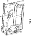
- FIG. 9 is a perspective view illustrating an arrangement of the restricting member 3 as seen from the reverse side of the front cover 101.
- FIG. 9 illustrates a state of the restricting member 3 when the image forming apparatus 100 is manufactured and transported. As illustrated in FIG. 9 , the restricting member 3 is located on a central portion of the front cover 101.
- the restricting member 3 restricts the front cover 101 from closing.
- the restricting member 3 includes a rotary member 31 and a recess 32.
- the rotary member 31 protrudes from the front cover 101 on the reverse surface of the front cover 101.
- the rotary member 31 is freely rotatable in the direction D3.
- the recess 32 is recessed into the front cover 101 in a thickness direction thereof.
- the recess 32 is covered by the rotary member 31 when the rotary member 31 is rotated in the direction D3.
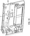
- FIG. 10 is a perspective view illustrating the arrangement of the restricting member 3 as seen from the reverse side of the front cover 101.
- the front cover 101 is open.
- the recess 32 of the restricting member 3 is covered by the rotary member 31 when the front cover 101 is open.
- the state of the rotary member 31 protruding from the front cover 101 on the reverse surface of the front cover 101 as illustrated in FIG. 9 may be referred to as the restricting member 3 being in a "protruding state”.
- the state in which the recess 32 is covered by the rotary member 31 as illustrated in FIG. 10 may be referred to as the restricting member 3 being in a "covered state”.
- FIG. 11 is a perspective view illustrating a structure of the restricting member 3.
- FIG. 11 illustrates a state of the restricting member 3 when the image forming apparatus 100 is manufactured and transported similarly to FIG. 9 .
- the restricting member 3 further includes an urging member 33.
- the urging member 33 urges the rotary member 31 in the direction D3.
- the urging member 33 is a "torsion coil spring", for example.
- the urging member 33 has an end portion 331 on one side thereof and an end portion 332 on an opposite side thereof.
- the rotary member 31 includes a base section 31A, two side plates 31B, a securing member 311, and the supporting member 312.
- the base section 31A is flatly rectangular plate-shaped and covers the recess 32 when rotated in the direction D3.
- the two side plates 31B are erected in a direction perpendicular to the base section 31A on respective ends of the base section 31A in a longitudinal direction thereof (left-right direction in FIG. 11 ).
- the two side plates 31B are integral with the base section 31A.
- the securing member 311 and the supporting member 312 are located on one side plate 31B (right in FIG. 11 ) of the two side plates 31B.
- the securing member 311 is located on an end of the one side plate 31B near the base section 31A.
- the securing member 311 protrudes in a direction away from the other side plate 31B (rightward in FIG. 11 ).
- the securing member 311 secures the end portion 331 of one of ends of the urging member 33.
- the supporting member 312 is located on an end (lower end in FIG. 11 ) of the one side plate 31B away from the base section 31A.
- the supporting member 312 protrudes in a direction away from the other side plate 31B (rightward in FIG. 11 ).
- the supporting member 312 rotatably supports the base section 31A and the two side plates 31B.
- the supporting member 312 supports the urging member 33. Specifically, the supporting member 312 is inserted through a coil portion of the urging member 33.
- a base plate 321 is provided to serve as a bottom of the recess 32.
- the base plate 321 is a plate-shaped member located at the bottom of the recess 32.
- the end portion 332 of the urging member 33 on the opposite side thereof is secured while in contact with the base plate 321.
- the supporting member 312 is inserted through the coil portion of the urging member 33.
- the end portion 331 of the urging member 33 on the one side thereof is secured to the securing member 311.
- the end portion 332 of the urging member 33 on the other side thereof is secured while in contact with the base plate 321.
- the urging member 33 urges the rotary member 31 in the direction D3 through the securing member 311.
- FIG. 12 is a perspective view illustrating the structure of the restricting member 3.
- the front cover 101 is open.
- the recess 32 of the restricting member 3 is covered by the rotary member 31 when the front cover 101 is open. That is, when the rotary member 31 rotates about the supporting member 312 due to the urging member 33 urging the rotary member 31 in the direction D3 as illustrated in FIG. 11 , the base section 31A of the rotary member 31 covers the recess 32 as illustrated in FIG. 12 . That is, the restricting member 3 changes from the protruding state to the covered state.
- FIG. 13 is a cross-sectional view illustrating the restricting member 3 and the toner container TC in transport. As illustrated in FIG. 13 , the restricting member 3 is in the protruding state.
- the toner container TC has a first outer peripheral surface TC1, a second outer peripheral surface TC2, and a third outer peripheral surface TC3.
- the first outer peripheral surface TC1 is flatly plate-shaped.
- the second outer peripheral surface TC2 is flatly plate-shaped.
- the third outer peripheral surface TC3 is disk-shaped.
- One end of the first outer peripheral surface TC1 is connected to the second outer peripheral surface TC2, and an opposite end of the first outer peripheral surface TC1 is connected to the third outer peripheral surface TC3.
- One end of the second outer peripheral surface TC2 is connected to the first outer peripheral surface TC1, and an opposite end of the second outer peripheral surface TC2 is connected to the third outer peripheral surface TC3.
- One end of the third outer peripheral surface TC3 is connected to the first outer peripheral surface TC1, and an opposite end of the third outer peripheral surface TC3 is connected to the second outer peripheral surface TC2.
- the toner container TC has a toner discharge port TCA. Toner is discharged from the toner container TC through the toner discharge port TCA.
- a posture of the toner container TC can be changed between a first posture and a second posture.
- the first posture is a posture in which toner is enabled to be supplied from the toner discharge port TCA of the toner container TC to the image forming section 14 (development section 145).
- the second posture is a posture in which the toner discharge port TCA is blocked.
- the toner container TC illustrated in FIG. 13 takes the second posture.
- the toner container TC includes a connecting portion CP.
- the connecting portion CP serves as a peripheral surface of the toner container TC in a position in which the first outer peripheral surface TC1 is connected to the third outer peripheral surface TC3.
- the connecting portion CP is fitted into the recess 32 of the restricting member 3. Therefore, the front cover 101 can be closed even when the toner container TC is in the second posture.
- FIG. 14 is a cross-sectional view illustrating the restricting member 3 and the toner container TC after the front cover 101 is opened.
- the restricting member 3 illustrated in FIG. 14 is in the covered state, unlike the restricting member 3 as illustrated in FIG. 13 .
- the restricting member 3 is put in the covered state as described with reference to FIGS. 9 to 12 . That is, the rotary member 31 (base section 31A) of the restricting member 3 covers the recess 32.
- the rotary member 31 makes contact with the connecting portion CP of the toner container TC.
- the front cover 101 cannot be closed. That is, when the toner container TC is in the second posture, the restricting member 3 restricts the front cover 101 from closing. Specifically, the restricting member 3 prohibits the front cover 101 from closing.
- FIG. 15 is a cross-sectional view illustrating the restricting member 3 and the toner container TC when the front cover 101 is closed.
- the toner container TC illustrated in FIG. 15 is in the first posture, unlike the toner container TC illustrated in FIG. 14 . That is, as illustrated in FIG. 14 , the toner container TC is rotated by the user in a direction D4 to change the toner container TC from the second posture illustrated in FIG. 14 to the first posture.
- the first outer peripheral surface TC1 of the toner container TC is parallel to an X-Y plane.
- the toner can be supplied through the toner discharge port TCA of the toner container TC to the image forming section 14 (development section 145).
- the connecting portion CP is positioned above the rotary member 31 of the restricting member 3. Therefore, the front cover 101 can be closed without the rotary member 31 making contact with the connecting portion CP. That is, when the toner container TC is in the first posture, the restricting member 3 allows the front cover 101 to close.
- the restricting member 3 when the toner container TC is in the first posture, the restricting member 3 allows the front cover 101 to close.
- the restricting member 3 prohibits the front cover 101 from closing. Therefore, the user must change the toner container TC from the second posture to the first posture to close the front cover 101. Accordingly, the user can be led to put the toner container TC in the first posture.
- FIG. 16A is a perspective view illustrating an arrangement of the posture displaying members M1 and M2 when the toner container TC is in the second posture.
- FIG. 16B is an enlarged perspective view illustrating the arrangement of the posture displaying members M1 and M2 when the toner container TC is in the second posture.
- the image forming apparatus 100 further includes the posture displaying member M1.
- the posture displaying member M1 is located on the toner supply section 13.
- the posture displaying member M1 is located adjacent to an end of the toner container TC in the negative Y axis direction on the toner supply section 13.
- the posture displaying member M1 faces aslant by 45° in the X axis direction from the Z axis in the X-Z plane.
- the toner container TC further includes the posture displaying member M2.
- the posture displaying member M2 is located on an end (upper right end in FIG. 16B ) of the toner container TC near the posture displaying member M1 of the toner supply section 13.
- the posture displaying member M2 is located lower than a position opposite to the posture displaying member M1. Therefore, when the posture displaying member M2 is located beneath the posture displaying member M1, the posture displaying member M1 and the posture displaying member M2 indicate that the toner container TC is in the second posture.
- the posture displaying member M1 and the posture displaying member M2 constitute an example of a second displaying member.
- FIG. 17A is a perspective view illustrating an arrangement of the posture displaying members M1 and M2 when the toner container TC is in the first posture.
- FIG. 17B is an enlarged perspective view illustrating the arrangement of the posture displaying members M1 and M2 when the toner container TC is in the first posture.
- the posture displaying member M2 when the toner container TC is in the first posture, the posture displaying member M2 is located opposite to the posture displaying member M1. Therefore, when the posture displaying member M2 is located opposite to the posture displaying member M1, the posture displaying member M1 and the posture displaying member M2 indicate that the toner container TC is in the first posture.
- the toner container TC is attachable and detachable when the front cover 101 is open. Therefore, the position of the toner container TC can be adjusted when the front cover 101 is open. Accordingly, the toner container TC can be changed from the second posture to the first posture.
- the posture displaying member M1 and the posture displaying member M2 indicate whether the toner container TC is in the first posture or the second posture. Therefore, the user can ascertain whether the toner container TC is in the first posture or the second posture. Accordingly, the user can be led to put the toner container TC in the first posture.
Landscapes
- Physics & Mathematics (AREA)
- General Physics & Mathematics (AREA)
- Engineering & Computer Science (AREA)
- Microelectronics & Electronic Packaging (AREA)
- Electrophotography Configuration And Component (AREA)
- Accessory Devices And Overall Control Thereof (AREA)
- Dry Development In Electrophotography (AREA)
Abstract
Description
- The present disclosure relates to a power supply lock structure and an image forming apparatus.
- An example of an image forming apparatus includes a casing, a development device, and a toner container. The casing includes a front cover. The development device includes a toner replenishment port. When the front cover is open, the development device is detachable from the casing through an insertion path after moving to a standby position. The standby position is a position in which the development device has been rotated in a first direction from a development position around a first axis that is parallel to a rotary shaft of a photosensitive drum. In a state in which the front cover is open and the development device is in the development position or the standby position, the toner container is detachable from the casing through the insertion path after rotating in a second direction around a second axis. The second axis is parallel to the first axis. The second direction is opposite to the first direction.
- Therefore, in the above image forming apparatus, the development device and the toner container can be easily detached from the casing. When being manufactured and transported, the image forming apparatus is arranged in a posture in which toner is not supplied from the toner container. Therefore, a user must open a cover and change the posture of the toner container so that toner can be supplied from the toner container. When being transported, operating instructions describing operation steps for the user to put the transported image forming apparatus into a usable state are affixed to the image forming apparatus.
- A power supply lock structure according to an aspect of the present disclosure includes a power button and a locking mechanism. The power button switches a power supply between on and off. The locking mechanism prohibits operation of the power button. The locking mechanism is located on a cover. Prohibition of the operation of the power supply is releasable by the locking mechanism only when the cover is open.
- An image forming apparatus according to an aspect of the present disclosure includes a power supply lock structure, an image forming section, and a casing. The image forming section forms an image on a recording medium. The casing includes a cover and houses the image forming section. The power supply lock structure includes a power button and a locking mechanism. The power button switches a power supply between on and off. The locking mechanism prohibits operation of the power supply by the power button. The locking mechanism is located on the cover. Prohibition of the operation of the power supply is releasable by the locking mechanism only when the cover is open.
-
-
FIG. 1 is a diagram illustrating a configuration of an image forming apparatus according to an embodiment of the present disclosure. -
FIG. 2 is a perspective view illustrating the configuration of the image forming apparatus. -
FIG. 3 is a perspective view illustrating an arrangement of a power supply lock structure according to the embodiment of the present disclosure. -
FIG. 4 is an exploded perspective view illustrating a configuration of the power supply lock structure. -
FIG. 5 is a front view of a locking mechanism as seen from behind a front cover. -
FIG. 6 is a cross-sectional view of the locking mechanism illustrated inFIG. 5 taken along a line VI-VI. -
FIG. 7 is a cross-sectional view illustrating the locking mechanism in a locked state. -
FIG. 8 is a cross-sectional view illustrating the locking mechanism in an unlocked state. -
FIG. 9 is a perspective view illustrating an arrangement of a restricting member according to the embodiment of the present disclosure. -
FIG. 10 is a perspective view illustrating the restricting member when the front cover is open. -
FIG. 11 is a perspective view illustrating a structure of the restricting member. -
FIG. 12 is a perspective view illustrating the structure of the restricting member. -
FIG. 13 is a cross-sectional view illustrating the restricting member and a toner container in transport. -
FIG. 14 is a cross-sectional view illustrating the restricting member and the toner container after the front cover is opened. -
FIG. 15 is a cross-sectional view illustrating the restricting member and the toner container when the front cover is closed. -
FIG. 16A is a perspective view illustrating an arrangement of posture displaying members when the toner container is in a second posture.FIG. 16B is an enlarged perspective view illustrating the arrangement of the posture displaying members when the toner container is in the second posture. -
FIG. 17A is a perspective view illustrating the arrangement of the posture displaying members when the toner container is in a first posture.FIG. 17B is an enlarged perspective view illustrating the arrangement of the posture displaying members when the toner container is in the first posture. - In the following, an embodiment of the present disclosure is described with reference to the accompanying drawings (
FIGS. 1 to 17B ). Note that elements that are the same or equivalent are labelled with the same reference signs in the drawings and description thereof is not repeated. - First, an
image forming apparatus 100 according to the embodiment of the present disclosure is described with reference toFIGS. 1 and2 .FIG. 1 is a diagram illustrating a configuration of theimage forming apparatus 100. As illustrated inFIG. 1 , theimage forming apparatus 100 is a printer. - Mutually orthogonal X, Y, and Z axes are shown in
FIG. 1 . The X and Y axes are parallel to a horizontal plane. The Z axis is parallel to a vertical direction. In the following description, a positive X axis direction may be considered backward, and a negative X axis direction may be considered forward. - The
image forming apparatus 100 includes acasing 10, afeeding section 12, a conveyance section L, atoner supply section 13, animage forming section 14, afixing section 16, anejection roller pair 17, and anexit tray 18. Thecasing 10 houses thefeeding section 12, the conveyance section L, thetoner supply section 13, theimage forming section 14, thefixing section 16, and theejection roller pair 17. - The
feeding section 12 feeds paper P to the conveyance section L. The conveyance section L conveys the paper P to theejection roller pair 17 by way of theimage forming section 14 and thefixing section 16. - A toner container TC is attached to the
toner supply section 13. The toner container TC supplies toner to theimage forming section 14. - The
image forming section 14 includes aphotosensitive drum 141, acharger 142, alight exposure section 143, adevelopment section 145, atransfer roller 146, and acleaning section 147. - The
charger 142 charges thephotosensitive drum 141 to a predetermined potential. Thelight exposure section 143 radiates laser light to expose thephotosensitive drum 141 to the laser light, thus forming an electrostatic latent image on thephotosensitive drum 141. Thedevelopment section 145 supplies toner to thephotosensitive drum 141, thus developing the electrostatic latent image into a toner image. In this manner, a toner image is formed on a peripheral surface of thephotosensitive drum 141. Thetransfer roller 146 transfers the toner image from thephotosensitive drum 141 to the paper P. As a result, an image is formed on the paper P. Thecleaning section 147 removes remaining toner from the peripheral surface of thephotosensitive drum 141. - The paper P with the image formed thereon is conveyed to the fixing
section 16. The fixingsection 16 applies heat and pressure to the paper P, thus fixing the image formed on the paper P to the paper P. The paper P with the image fixed thereon is ejected to theexit tray 18 by theejection roller pair 17. - The
casing 10 includes afront cover 101. Thefront cover 101 is open in attachment and detachment of the toner container TC. Thefront cover 101 includes a covermain body 101A and asupport shaft 101B. Thesupport shaft 101B is a cylindrical member extending in a Y axis direction. Thesupport shaft 101B rotatably supports the covermain body 101A. The covermain body 101A is flatly plate-shaped and is configured to rotate in a direction D1 as indicated by an arrow D1 about thesupport shaft 101B serving as a fulcrum thereof. Thefront cover 101 is equivalent to an example of a "cover". -
FIG. 2 is a perspective view illustrating the configuration of theimage forming apparatus 100. As illustrated inFIG. 2 , theimage forming apparatus 100 further includes a powersupply lock structure 2. The powersupply lock structure 2 is located on an end of thefront cover 101 in a negative Y axis direction. - Next, an arrangement of the power
supply lock structure 2 according to the embodiment of the present disclosure is described with reference toFIGS. 1 to 3 .FIG. 3 is a perspective view illustrating the arrangement of the powersupply lock structure 2. InFIG. 3 , thefront cover 101 is open. As illustrated inFIG. 3 , the powersupply lock structure 2 is located on a back surface of thefront cover 101. - Next, a configuration of the power
supply lock structure 2 is described with reference toFIGS. 1 to 4 .FIG. 4 is an exploded perspective view illustrating the configuration of the powersupply lock structure 2. As illustrated inFIG. 4 , the powersupply lock structure 2 includes apower button 21 and alocking mechanism 20. Thelocking mechanism 20 includes a supportingmember 22 and arotary member 23. - The
power button 21 has abutton 211 and ashaft member 212. Thebutton 211 is disk-shaped and is pressed by a user when power is switched on or off. Thebutton 211 is exposed on a front surface of thefront cover 101. That is, the user can press thebutton 211 to switch a power supply between on and off when thefront cover 101 is closed. The front surface faces in the negative X axis direction and is equivalent to an "obverse surface". - The
shaft member 212 supports thebutton 211. Theshaft member 212 extends in an X axis direction. That is, an axial direction of theshaft member 212 is parallel to the X axis. A cross section of theshaft member 212 in a direction perpendicular to the axial direction of theshaft member 212 is cross-shaped. The direction perpendicular to the axial direction of theshaft member 212 is a direction parallel to a Y-Z plane. - The
shaft member 212 is inserted through the supportingmember 22 and therotary member 23. Theshaft member 212 has a steppedportion 213. In the steppedportion 213, theshaft member 212 is tapered in the positive X axis direction. That is, in the steppedportion 213, a size of the cross section in a direction perpendicular to the axial direction of theshaft member 212 decreases in steps in the positive X axis direction. The steppedportion 213 is in contact with therotary member 23. - The
locking mechanism 20 prohibits movement of theshaft member 212 in the axial direction of theshaft member 212. Thelocking mechanism 20 is located on the back surface of thefront cover 101. Therefore, thelocking mechanism 20 can release prohibition of operation of the power supply only when thefront cover 101 is open. The back surface faces in the positive X axis direction and is equivalent to a "reverse surface". - The supporting
member 22 is secured to thefront cover 101 and rotatably supports therotary member 23. The supportingmember 22 includes abase member 221, afirst guide member 222, and asecond guide member 224. Thebase member 221 is rectangular plate-shaped. Thebase member 221 has a lock displaying section MC, an unlock displaying section MP, and aninsertion hole 225. - The lock displaying section MC and the unlock displaying section MP are located on a back surface of the
base member 221. A mark of a locked padlock is displayed on the lock displaying section MC. A mark of an unlocked padlock is displayed on the unlock displaying section MP. - The
insertion hole 225 is a round hole formed in a central portion of thebase member 221. Theshaft member 212 is inserted through theinsertion hole 225. - The
first guide member 222 is a hollow rectangular prism-shaped member erected on thebase member 221 in the positive X axis direction. A portion of therotary member 23 is inserted into thefirst guide member 222. Thefirst guide member 222 includes four protrudingmembers 223. Each of the four protrudingmembers 223 is a plate-shaped member erected inward on an end of thefirst guide member 222 in the positive X axis direction. The four protrudingmembers 223 include a first protrudingmember 223A, a second protrudingmember 223B, a third protruding member 223C, and a fourth protrudingmember 223D. - The first protruding
member 223A is located on a side of thefirst guide member 222 in a positive Z axis direction. The second protrudingmember 223B is located on a side of thefirst guide member 222 in a negative Z axis direction. The third protruding member 223C is located on a side of thefirst guide member 222 in the negative Y axis direction. The fourth protrudingmember 223D is located on a side of thefirst guide member 222 in a positive Y axis direction. The first protrudingmember 223A and the second protrudingmember 223B are located opposite to each other. The third protruding member 223C and the fourth protrudingmember 223D are located opposite to each other. - The
second guide member 224 is a cylindrical member erected on thebase member 221 in the positive X axis direction. Thesecond guide member 224 is located between theinsertion hole 225 and thefirst guide member 222. A portion of therotary member 23 is inserted between thesecond guide member 224 and thefirst guide member 222. - The
rotary member 23 is cylindrical and is rotatably supported by the supportingmember 22. Specifically, an end of therotary member 23 in the negative X axis direction is in contact with a surface of thebase member 221 of the supportingmember 22 in the positive X axis direction. Therotary member 23 includes agrip section 231, four engagingmembers 232, and an indicatingmember 234. - The
grip section 231 has a plurality of grooves on a side of therotary member 23 in the positive X axis direction. Specifically, each of the grooves composing thegrip section 231 linearly extends in the X axis direction in an outer peripheral surface of therotary member 23. Thegrip section 231 is gripped by the user rotating therotary member 23. - Each of the four
engaging members 232 is a rectangular plate-shaped member erected on the end of therotary member 23 in the negative X axis direction. Each of the fourengaging members 232 is erected outward on the outer peripheral surface of therotary member 23. That is, each of the fourengaging members 232 is erected in a direction away from a central axis of therotary member 23. - The four
engaging members 232 include a first engagingmember 232A, a second engagingmember 232B, a third engagingmember 232C, and a fourth engagingmember 232D. The first engagingmember 232A engages with the first protrudingmember 223A. The second engagingmember 232B engages with the second protrudingmember 223B. The third engagingmember 232C engages with the third protruding member 223C. The fourth engagingmember 232D engages with the fourth protrudingmember 223D. - When the first engaging
member 232A engages with the first protrudingmember 223A, the second engagingmember 232B engages with the second protrudingmember 223B, the third engagingmember 232C engages with the third protruding member 223C, and the fourth engagingmember 232D engages with the fourth protrudingmember 223D. That is, the fourengaging members 232 respectively engage with the four protrudingmembers 223 at the same time. The fourengaging members 232 also respectively release engagement from the four protrudingmembers 223 at the same time. - Specifically, when the
rotary member 23 is in a "first rotational position", the fourengaging members 232 engage with the respective four protrudingmembers 223. When therotary member 23 is in a "second rotational position", the fourengaging members 232 are released from engagement with the respective four protrudingmembers 223. - The first rotational position and the second rotational position are described later in detail with reference to
FIG. 5 . In the following description, the fourengaging members 232 engaging with the respective four protrudingmembers 223 may be simply referred to as "the engagingmembers 232 engaging with the protrudingmembers 223". Also, the fourengaging members 232 releasing from engagement with the respective four protrudingmembers 223 may be simply referred to as "the engagingmembers 232 being released from engagement with the protrudingmembers 223". - Movement of the
shaft member 212 in the axial direction of theshaft member 212 is prohibited by the engagingmembers 232 engaging with the protrudingmembers 223, thus prohibiting operation of thepower button 21. Also, prohibition of movement of theshaft member 212 in the axial direction of theshaft member 212 is released by the engagingmembers 232 being released from engagement with the protrudingmembers 223, thus releasing prohibition of the operation of thepower button 21. - The indicating
member 234 indicates whether therotary member 23 is in the first rotational position or the second rotational position. The indicatingmember 234 is a triangular plate-shaped member erected on a central portion of therotary member 23 in the X axis direction. When a distal end of the indicatingmember 234 is in a position opposite to the lock displaying section MC, the indicatingmember 234 indicates that therotary member 23 is in the first rotational position. When the distal end of the indicatingmember 234 is in a position opposite to the unlock displaying section MP, the indicatingmember 234 indicates that therotary member 23 is in the second rotational position. The indicatingmember 234, the lock displaying section MC, and the unlock displaying section MP constitute an example of a "first displaying member". - As described above with reference to
FIGS. 1 to 4 , thelocking mechanism 20 is located on thefront cover 101 and can release prohibition of the operation of the power supply only when thefront cover 101 is open. Therefore, it is necessary to open thefront cover 101 for turning on the power. Accordingly, the user can be led to open thefront cover 101. - Because the
locking mechanism 20 is located on the reverse surface of thefront cover 101, thelocking mechanism 20 can release prohibition of the operation of the power supply only when thefront cover 101 is open. Specifically, the user can rotate therotary member 23 from the first rotational position to the second rotational position only when thefront cover 101 is open. Accordingly, the user can be led to open thefront cover 101. - Furthermore, the
power button 21 is located on the obverse surface of thefront cover 101. Therefore, the user can switch the power supply between on and off with thefront cover 101 closed when the prohibition of the operation of the power supply is released. Accordingly, convenience for the user can be improved. - The
power button 21 includes theshaft member 212 which supports thebutton 211, and thelocking mechanism 20 prohibits movement of theshaft member 212 in the axial direction of theshaft member 212. Accordingly, the operation of the power supply can be prohibited with a simple configuration. - Note that the cover is the
front cover 101 in the embodiment of the present disclosure, but the present disclosure is not limited as such. It is only required that the cover be located on thecasing 10. For example, the cover may be an upper cover located on an upper surface of thecasing 10. - Also the
locking mechanism 20 is located on the reverse surface of thefront cover 101 in the embodiment of the present disclosure, but the present disclosure is not limited as such. It is only required that thelocking mechanism 20 be located on thefront cover 101 and be capable of releasing prohibition of the operation of the power supply only when thefront cover 101 is open. For example, thelocking mechanism 20 may be located on an upper end of thefront cover 101 and be hidden by an upper cover when thefront cover 101 is closed. - Furthermore, the
first guide member 222 includes the four protrudingmembers 223 and therotary member 23 includes the fourengaging members 232 in the embodiment of the present disclosure, but the present disclosure is not limited as such. It is only required that thefirst guide member 222 include at least one protrudingmember 223 and therotary member 23 include at least one engagingmember 232. For example, thefirst guide member 222 may have two protrudingmembers 223 and therotary member 23 may have twoengaging members 232. - Next, the first rotational position and the second rotational position are described with reference to
FIGS. 3 to 5 .FIG. 5 is a front view of thelocking mechanism 20 as seen from behind thefront cover 101. As illustrated inFIG. 5 , the distal end of the indicatingmember 234 is in a position opposite to the lock displaying section MC. That is, the indicatingmember 234 points to the lock displaying section MC. The first rotational position is a position of therotary member 23 in a rotational direction in which the indicatingmember 234 points to the lock displaying section MC. When therotary member 23 is in the first rotational position, the engagingmembers 232 engage with the protrudingmembers 223 and prohibit movement of theshaft member 212 in the axial direction of theshaft member 212. As a result, the operation of the power supply is prohibited. - The user can move the
rotary member 23 from the first rotational position to the second rotational position by gripping thegrip section 231 of therotary member 23 and rotating therotary member 23 clockwise as indicated by a direction D2. The second rotational position is a position of therotary member 23 in the rotational direction in which the indicatingmember 234 points to the unlock displaying section MP. When therotary member 23 is in the second rotational position, the engagingmembers 232 is released from engagement with the protrudingmembers 223, thus releasing prohibition of movement of theshaft member 212 in the axial direction of theshaft member 212. As a result, prohibition of the operation of the power supply is released. - The
rotary member 23 further includes aplate member 233. Theplate member 233 is a disk-shaped member secured to an inner peripheral surface of therotary member 23. Theplate member 233 is arranged parallel to the Y-Z plane. Theplate member 233 has aninsertion hole 235. - The
insertion hole 235 is a hole formed in a central portion of theplate member 233. Theinsertion hole 235 includes acenter hole 235A and fourperipheral holes 235B. Thecenter hole 235A is a round hole formed in the central portion of theplate member 233. Each of the fourperipheral holes 235B is a rectangular hole communicating with thecenter hole 235A and protruding away from the center of thecenter hole 235A. An angle between two line segments connecting the centers of two adjacent among the fourperipheral holes 235B with the center of thecenter hole 235A is 90°. - The
shaft member 212 is inserted through theinsertion hole 235. The steppedportion 213 of theshaft member 212 is in contact with a surface of theplate member 233 in the negative X axis direction. Specifically, the steppedportion 213 of theshaft member 212 makes contact with a surface of theplate member 233 in the negative X-axis direction on a peripheral edge of each of the fourperipheral holes 235B in a direction away from the center of thecenter hole 235A. When theshaft member 212 moves in the axial direction of theshaft member 212, theshaft member 212 moves together with therotary member 23. - In the embodiment of the present disclosure as described above with reference to
FIGS. 3 to 5 , the indicatingmember 234, the lock displaying section MC, and the unlock displaying section MP indicate whether therotary member 23 is in the first rotational position or the second rotational position. When therotary member 23 is in the first rotational position, the operation of the power supply is prohibited. When therotary member 23 is in the second rotational position, the prohibition of the operation of the power supply is released. Accordingly, the user can easily release the prohibition of the operation of the power supply. - Next, the configuration of the
locking mechanism 20 is further described with reference toFIGS. 3 to 8 .FIG. 6 is a cross-sectional view of thelocking mechanism 20 illustrated inFIG. 5 taken along a line VI-VI. As illustrated inFIG. 6 , the first engagingmember 232A of therotary member 23 engages with the first protrudingmember 223A of thefirst guide member 222. That is, therotary member 23 is in the first rotational position. - The first engaging
member 232A moves in a direction D3 due to the user gripping thegrip section 231 of therotary member 23 and rotating therotary member 23 clockwise as indicated by the direction D2 illustrated inFIG. 5 . As a result, the first engagingmember 232A is released from engagement with the first protrudingmember 223A. That is, the first engagingmember 232A is released from engagement with the first protrudingmember 223A due to therotary member 23 rotating from the first rotational position to the second rotational position. -
FIG. 7 is a cross-sectional view illustrating thelocking mechanism 20 in a locked state. As illustrated inFIG. 7 , the first engagingmember 232A of therotary member 23 engages with the first protrudingmember 223A of thefirst guide member 222, and the second engagingmember 232B of therotary member 23 engages with the second protrudingmember 223B of thefirst guide member 222. As a result, thelocking mechanism 20 prohibits movement of theshaft member 212 in the axial direction of theshaft member 212. Specifically, the steppedportion 213 of theshaft member 212 makes contact with theplate member 233, thus prohibiting movement of theshaft member 212 in the axial direction of theshaft member 212. That is, the prohibition of the operation of the power supply is released. - As illustrated in
FIG. 7 , thelocking mechanism 20 further includes a first urgingmember 24 and a second urgingmember 25. The first urgingmember 24 in a compressed state is located between thebutton 211 of thepower button 21 and thebase member 221 of the supportingmember 22. The first urgingmember 24 is for example a coil spring. The "compressed state" means a state in which a length of the coil spring is shorter than a natural length thereof. Theshaft member 212 is inserted through the first urgingmember 24. The first urgingmember 24 urges thebutton 211 in the negative X axis direction. - The
second urging member 25 in an extended state is located between thebase member 221 of the supportingmember 22 and theplate member 233 of therotary member 23. An end of the second urgingmember 25 in the negative X axis direction is secured to thebase member 221, and an end of the second urgingmember 25 in the positive X axis direction is secured to theplate member 233. Thesecond urging member 25 is for example a coil spring. The "extended state" means a state in which a length of the coil spring is longer than the natural length thereof. Theshaft member 212 is inserted through the second urgingmember 25. Thesecond urging member 25 urges therotary member 23 in the negative X axis direction. -
FIG. 8 is a cross-sectional view illustrating thelocking mechanism 20 in an unlocked state. As illustrated inFIG. 8 , the first engagingmember 232A of therotary member 23 is released from engagement with the first protrudingmember 223A of thefirst guide member 222, and the second engagingmember 232B of therotary member 23 is released from engagement with the second protrudingmember 223B of thefirst guide member 222. As a result, thelocking mechanism 20 releases the prohibition of movement of theshaft member 212 in the axial direction of theshaft member 212. Specifically, when thebutton 211 is pressed, the steppedportion 213 of theshaft member 212 makes contact with theplate member 233 and theshaft member 212 moves in the positive X axis direction together with therotary member 23. That is, the prohibition of the operation of the power supply is released. - In the embodiment of the present disclosure as described above with reference to
FIGS. 3 to 8 , movement of theshaft member 212 in the axial direction of theshaft member 212 is prohibited by the engagingmembers 232 of therotary member 23 engaging with the protrudingmembers 223 of the supportingmember 22. Engagement of the engagingmembers 232 with the protrudingmembers 223 is released by therotary member 23 rotating from the first rotational position to the second rotational position. Therefore, prohibition of the operation of the power supply can be released by rotating therotary member 23. Accordingly, prohibition of the operation of the power supply can be released with a simple operation. - Next, a configuration of the restricting
member 3 according to the embodiment of the present disclosure is described with reference toFIGS. 1 ,2 , and9 to 12 .FIG. 9 is a perspective view illustrating an arrangement of the restrictingmember 3 as seen from the reverse side of thefront cover 101.FIG. 9 illustrates a state of the restrictingmember 3 when theimage forming apparatus 100 is manufactured and transported. As illustrated inFIG. 9 , the restrictingmember 3 is located on a central portion of thefront cover 101. - The restricting
member 3 restricts thefront cover 101 from closing. The restrictingmember 3 includes arotary member 31 and arecess 32. Therotary member 31 protrudes from thefront cover 101 on the reverse surface of thefront cover 101. Therotary member 31 is freely rotatable in the direction D3. Therecess 32 is recessed into thefront cover 101 in a thickness direction thereof. Therecess 32 is covered by therotary member 31 when therotary member 31 is rotated in the direction D3. -
FIG. 10 is a perspective view illustrating the arrangement of the restrictingmember 3 as seen from the reverse side of thefront cover 101. InFIG. 10 , thefront cover 101 is open. As illustrated inFIG. 10 , therecess 32 of the restrictingmember 3 is covered by therotary member 31 when thefront cover 101 is open. In the following description, the state of therotary member 31 protruding from thefront cover 101 on the reverse surface of thefront cover 101 as illustrated inFIG. 9 may be referred to as the restrictingmember 3 being in a "protruding state". Also, the state in which therecess 32 is covered by therotary member 31 as illustrated inFIG. 10 may be referred to as the restrictingmember 3 being in a "covered state". -
FIG. 11 is a perspective view illustrating a structure of the restrictingmember 3.FIG. 11 illustrates a state of the restrictingmember 3 when theimage forming apparatus 100 is manufactured and transported similarly toFIG. 9 . As illustrated inFIG. 11 , the restrictingmember 3 further includes an urgingmember 33. The urgingmember 33 urges therotary member 31 in the direction D3. The urgingmember 33 is a "torsion coil spring", for example. The urgingmember 33 has anend portion 331 on one side thereof and anend portion 332 on an opposite side thereof. - The
rotary member 31 includes abase section 31A, twoside plates 31B, a securingmember 311, and the supportingmember 312. Thebase section 31A is flatly rectangular plate-shaped and covers therecess 32 when rotated in the direction D3. The twoside plates 31B are erected in a direction perpendicular to thebase section 31A on respective ends of thebase section 31A in a longitudinal direction thereof (left-right direction inFIG. 11 ). The twoside plates 31B are integral with thebase section 31A. The securingmember 311 and the supportingmember 312 are located on oneside plate 31B (right inFIG. 11 ) of the twoside plates 31B. - The securing
member 311 is located on an end of the oneside plate 31B near thebase section 31A. The securingmember 311 protrudes in a direction away from theother side plate 31B (rightward inFIG. 11 ). The securingmember 311 secures theend portion 331 of one of ends of the urgingmember 33. - The supporting
member 312 is located on an end (lower end inFIG. 11 ) of the oneside plate 31B away from thebase section 31A. The supportingmember 312 protrudes in a direction away from theother side plate 31B (rightward inFIG. 11 ). The supportingmember 312 rotatably supports thebase section 31A and the twoside plates 31B. The supportingmember 312 supports the urgingmember 33. Specifically, the supportingmember 312 is inserted through a coil portion of the urgingmember 33. - A
base plate 321 is provided to serve as a bottom of therecess 32. Thebase plate 321 is a plate-shaped member located at the bottom of therecess 32. Theend portion 332 of the urgingmember 33 on the opposite side thereof is secured while in contact with thebase plate 321. - The supporting
member 312 is inserted through the coil portion of the urgingmember 33. Theend portion 331 of the urgingmember 33 on the one side thereof is secured to the securingmember 311. Theend portion 332 of the urgingmember 33 on the other side thereof is secured while in contact with thebase plate 321. In this configuration, the urgingmember 33 urges therotary member 31 in the direction D3 through the securingmember 311. -
FIG. 12 is a perspective view illustrating the structure of the restrictingmember 3. InFIG. 12 , thefront cover 101 is open. As illustrated inFIG. 12 , therecess 32 of the restrictingmember 3 is covered by therotary member 31 when thefront cover 101 is open. That is, when therotary member 31 rotates about the supportingmember 312 due to the urgingmember 33 urging therotary member 31 in the direction D3 as illustrated inFIG. 11 , thebase section 31A of therotary member 31 covers therecess 32 as illustrated inFIG. 12 . That is, the restrictingmember 3 changes from the protruding state to the covered state. - Next, a relationship between the restricting
member 3 and the toner container TC is described with reference toFIGS. 1 ,2 , and9 to 15 .FIG. 13 is a cross-sectional view illustrating the restrictingmember 3 and the toner container TC in transport. As illustrated inFIG. 13 , the restrictingmember 3 is in the protruding state. The toner container TC has a first outer peripheral surface TC1, a second outer peripheral surface TC2, and a third outer peripheral surface TC3. - The first outer peripheral surface TC1 is flatly plate-shaped. The second outer peripheral surface TC2 is flatly plate-shaped. The third outer peripheral surface TC3 is disk-shaped.
- One end of the first outer peripheral surface TC1 is connected to the second outer peripheral surface TC2, and an opposite end of the first outer peripheral surface TC1 is connected to the third outer peripheral surface TC3. One end of the second outer peripheral surface TC2 is connected to the first outer peripheral surface TC1, and an opposite end of the second outer peripheral surface TC2 is connected to the third outer peripheral surface TC3. One end of the third outer peripheral surface TC3 is connected to the first outer peripheral surface TC1, and an opposite end of the third outer peripheral surface TC3 is connected to the second outer peripheral surface TC2.
- The toner container TC has a toner discharge port TCA. Toner is discharged from the toner container TC through the toner discharge port TCA. A posture of the toner container TC can be changed between a first posture and a second posture. The first posture is a posture in which toner is enabled to be supplied from the toner discharge port TCA of the toner container TC to the image forming section 14 (development section 145). The second posture is a posture in which the toner discharge port TCA is blocked.
- The toner container TC illustrated in
FIG. 13 takes the second posture. The toner container TC includes a connecting portion CP. The connecting portion CP serves as a peripheral surface of the toner container TC in a position in which the first outer peripheral surface TC1 is connected to the third outer peripheral surface TC3. When the toner container TC is in the second posture, the connecting portion CP is fitted into therecess 32 of the restrictingmember 3. Therefore, thefront cover 101 can be closed even when the toner container TC is in the second posture. -
FIG. 14 is a cross-sectional view illustrating the restrictingmember 3 and the toner container TC after thefront cover 101 is opened. The restrictingmember 3 illustrated inFIG. 14 is in the covered state, unlike the restrictingmember 3 as illustrated inFIG. 13 . When thefront cover 101 is opened as illustrated inFIG. 14 , the restrictingmember 3 is put in the covered state as described with reference toFIGS. 9 to 12 . That is, the rotary member 31 (base section 31A) of the restrictingmember 3 covers therecess 32. When rotating so that thefront cover 101 closes, therotary member 31 makes contact with the connecting portion CP of the toner container TC. As a result, thefront cover 101 cannot be closed. That is, when the toner container TC is in the second posture, the restrictingmember 3 restricts thefront cover 101 from closing. Specifically, the restrictingmember 3 prohibits thefront cover 101 from closing. -
FIG. 15 is a cross-sectional view illustrating the restrictingmember 3 and the toner container TC when thefront cover 101 is closed. The toner container TC illustrated inFIG. 15 is in the first posture, unlike the toner container TC illustrated inFIG. 14 . That is, as illustrated inFIG. 14 , the toner container TC is rotated by the user in a direction D4 to change the toner container TC from the second posture illustrated inFIG. 14 to the first posture. When the toner container TC is in the first posture, the first outer peripheral surface TC1 of the toner container TC is parallel to an X-Y plane. When the toner container is in the first posture, the toner can be supplied through the toner discharge port TCA of the toner container TC to the image forming section 14 (development section 145). - Because the toner container TC is in the first posture, the connecting portion CP is positioned above the
rotary member 31 of the restrictingmember 3. Therefore, thefront cover 101 can be closed without therotary member 31 making contact with the connecting portion CP. That is, when the toner container TC is in the first posture, the restrictingmember 3 allows thefront cover 101 to close. - In the embodiment of the present disclosure as described above with reference to
FIGS. 1 ,2 , and9 to 15 , when the toner container TC is in the first posture, the restrictingmember 3 allows thefront cover 101 to close. When the toner container TC is in the second posture, the restrictingmember 3 prohibits thefront cover 101 from closing. Therefore, the user must change the toner container TC from the second posture to the first posture to close thefront cover 101. Accordingly, the user can be led to put the toner container TC in the first posture. - Next, a configuration of a posture displaying member M1 and a posture displaying member M2 is described with reference to
FIGS. 1 ,2 ,16A, 16B ,17A, and 17B .FIG. 16A is a perspective view illustrating an arrangement of the posture displaying members M1 and M2 when the toner container TC is in the second posture.FIG. 16B is an enlarged perspective view illustrating the arrangement of the posture displaying members M1 and M2 when the toner container TC is in the second posture. As illustrated inFIGS. 16A and 16B , theimage forming apparatus 100 further includes the posture displaying member M1. The posture displaying member M1 is located on thetoner supply section 13. Specifically, the posture displaying member M1 is located adjacent to an end of the toner container TC in the negative Y axis direction on thetoner supply section 13. The posture displaying member M1 faces aslant by 45° in the X axis direction from the Z axis in the X-Z plane. - As illustrated in
FIG. 16B , the toner container TC further includes the posture displaying member M2. The posture displaying member M2 is located on an end (upper right end inFIG. 16B ) of the toner container TC near the posture displaying member M1 of thetoner supply section 13. When the toner container TC is in the second posture, the posture displaying member M2 is located lower than a position opposite to the posture displaying member M1. Therefore, when the posture displaying member M2 is located beneath the posture displaying member M1, the posture displaying member M1 and the posture displaying member M2 indicate that the toner container TC is in the second posture. The posture displaying member M1 and the posture displaying member M2 constitute an example of a second displaying member. -
FIG. 17A is a perspective view illustrating an arrangement of the posture displaying members M1 and M2 when the toner container TC is in the first posture.FIG. 17B is an enlarged perspective view illustrating the arrangement of the posture displaying members M1 and M2 when the toner container TC is in the first posture. As illustrated inFIGS. 17A and 17B , when the toner container TC is in the first posture, the posture displaying member M2 is located opposite to the posture displaying member M1. Therefore, when the posture displaying member M2 is located opposite to the posture displaying member M1, the posture displaying member M1 and the posture displaying member M2 indicate that the toner container TC is in the first posture. - As described above with reference to
FIGS. 1 ,2 ,16A, 16B ,17A, and 17B , the toner container TC is attachable and detachable when thefront cover 101 is open. Therefore, the position of the toner container TC can be adjusted when thefront cover 101 is open. Accordingly, the toner container TC can be changed from the second posture to the first posture. - The posture displaying member M1 and the posture displaying member M2 indicate whether the toner container TC is in the first posture or the second posture. Therefore, the user can ascertain whether the toner container TC is in the first posture or the second posture. Accordingly, the user can be led to put the toner container TC in the first posture.
- The embodiment of the present disclosure has been described so far with reference to the accompanying drawings. However, the present disclosure is not limited to the above-described embodiment and may be implemented in various manners within a scope not departing from the gist thereof (as below in (1) to (3), for example). The drawings are schematic illustrations that emphasize elements of configuration in order to facilitate understanding thereof. Properties of the elements of configuration illustrated in the drawings, such as thickness, length, and number thereof, may differ from actual properties thereof in order to facilitate preparation of the drawings. Properties of the elements of configuration illustrated in the above-described embodiment such as shape and size are examples, not particularly limited, and may be variously altered within a scope not substantially departing from the configuration of the present disclosure.
- (1) As described with reference to
FIG. 1 , theimage forming apparatus 100 is a printer, but the present disclosure is not limited as such. It is only required that theimage forming apparatus 100 include theimage forming section 14. For example, theimage forming apparatus 100 may be a multifunction peripheral. For another example, theimage forming apparatus 100 may be a copier. - (2) As described with reference to
FIGS. 1 to 3 , the powersupply lock structure 2 is located on thefront cover 101, but the present disclosure is not limited as such. It is only required that the powersupply lock structure 2 be located on a cover. For example, the powersupply lock structure 2 may be located on a back cover. For another example, the powersupply lock structure 2 may be located on an upper cover. - (3) As described with reference to
FIGS. 3 to 8 , thelocking mechanism 20 prohibits the operation of thepower button 21 by prohibiting movement of theshaft member 212 in the axial direction of theshaft member 212, but the present disclosure is not limited as such. It is only required that thelocking mechanism 20 prohibit the operation of thepower button 21. For example, thelocking mechanism 20 may open a power supply circuit.
Claims (10)
- A power supply lock structure (2), comprising:a power button (21) configured to switch a power supply between on and off; anda locking mechanism (20) configured to prohibit operation of the power button, whereinthe locking mechanism is located on a cover (101), and prohibition of the operation of the power supply is releasable by the locking mechanism only when the cover is open.
- The power supply lock structure according to claim 1, wherein
the locking mechanism is located on a reverse surface of the cover. - The power supply lock structure according claims 1 or 2, wherein
the power button is located on an obverse surface of the cover. - The power supply lock structure according to any one of claims 1 to 3, wherein
the power button includes:a button (211); anda shaft member (212) that supports the button,the button is secured to one end of the shaft member, and
the locking mechanism prohibits movement of the shaft member in an axial direction of the shaft member. - The power supply lock structure according to claim 4, wherein
the locking mechanism includes:a rotary member (23) that rotates together with the shaft member about an axis of the shaft member as a center; anda supporting member (22) that rotatably supports the rotary member,the shaft member is inserted through the rotary member,
the supporting member is secured to the cover,
the supporting member has a protruding member (223) that protrudes toward an outer periphery of the rotary member,
the rotary member includes an engaging member (232) that engages with the protruding member, and
when the engaging member engages with the protruding member, movement of the shaft member in the axial direction of the shaft member is prohibited. - The power supply lock structure according to claim 5, wherein
the locking mechanism further includes a first displaying member that indicates whether the rotary member is in a first rotational position or a second rotational position,
when the rotary member is in the first rotational position, movement of the shaft member in the axial direction of the shaft member is prohibited, and
when the rotary member is in the second rotational position, prohibition of movement of the shaft member in the axial direction of the shaft member is released. - An image forming apparatus (100), comprising:a power supply lock structure (2);an image forming section (14) configured to form an image on a recording medium (P); anda casing (10) including a cover (101) and configured to house the image forming section, whereinthe power supply lock structure includes:a power button (21) configured to switch a power supply between on and off; anda locking mechanism (20) configured to prohibit operation of the power supply by the power button, andthe locking mechanism is located on the cover, and prohibition of the operation of the power supply is releasable by the locking mechanism only when the cover is open.
- The image forming apparatus according to claim 7, wherein
a toner container (TC) is attachable to and detachable from the image forming section, and
when the cover is open, the toner container is attachable and detachable. - The image forming apparatus according to claim 8, further comprising
a restricting member (3) located on the cover and configured to restrict the cover from closing, wherein
the toner container has a toner discharge port (TCA) that discharges toner,
a posture of the toner container is changeable between a first posture and a second posture,
the first posture is a posture that enables the toner to be supplied through the toner discharge port to the image forming section,
the second posture is a posture in which the toner discharge port is blocked, and
the restricting member allows the cover to close when the toner container is in the first posture, and restricts the cover from closing when the toner container is in the second posture. - The image forming apparatus according to claim 9, further comprising
a second displaying member (M1, M2) configured to indicate whether the toner container is in the first posture or the second posture.
Applications Claiming Priority (1)
| Application Number | Priority Date | Filing Date | Title |
|---|---|---|---|
| JP2017241877A JP7027869B2 (en) | 2017-12-18 | 2017-12-18 | Power lock structure and image forming device |
Publications (2)
| Publication Number | Publication Date |
|---|---|
| EP3499313A1 true EP3499313A1 (en) | 2019-06-19 |
| EP3499313B1 EP3499313B1 (en) | 2020-10-21 |
Family
ID=64744404
Family Applications (1)
| Application Number | Title | Priority Date | Filing Date |
|---|---|---|---|
| EP18212989.0A Active EP3499313B1 (en) | 2017-12-18 | 2018-12-17 | Power supply lock structure and image forming apparatus |
Country Status (4)
| Country | Link |
|---|---|
| US (1) | US10627758B2 (en) |
| EP (1) | EP3499313B1 (en) |
| JP (1) | JP7027869B2 (en) |
| CN (1) | CN109932877B (en) |
Citations (4)
| Publication number | Priority date | Publication date | Assignee | Title |
|---|---|---|---|---|
| JP2008021436A (en) * | 2006-07-11 | 2008-01-31 | Murata Mach Ltd | Image forming device |
| JP2009265571A (en) * | 2008-04-30 | 2009-11-12 | Canon Inc | Image forming apparatus |
| DE102011088745A1 (en) * | 2011-12-15 | 2013-06-20 | Siemens Aktiengesellschaft | motor drive |
| US20170075256A1 (en) * | 2015-09-11 | 2017-03-16 | Kyocera Document Solutions Inc. | Image Forming Apparatus That Restrains Use of Apparatus in State Where Developer Is Not Replenishable |
Family Cites Families (16)
| Publication number | Priority date | Publication date | Assignee | Title |
|---|---|---|---|---|
| JP2562148B2 (en) * | 1987-08-20 | 1996-12-11 | 富士電機株式会社 | Push-button switch |
| JPH11168285A (en) * | 1997-12-04 | 1999-06-22 | Matsushita Electric Ind Co Ltd | Portable device with knob structure |
| JP4130742B2 (en) * | 2002-03-08 | 2008-08-06 | パナソニック コミュニケーションズ株式会社 | Copy machine or multifunction machine |
| JP4348150B2 (en) * | 2003-09-10 | 2009-10-21 | 株式会社リコー | Interlock switch mechanism and image forming apparatus having the same |
| US7398968B2 (en) | 2004-11-01 | 2008-07-15 | Hewlett-Packard Development Company, L.P. | Imaging apparatus |
| KR100785085B1 (en) * | 2005-02-07 | 2007-12-12 | 삼성전자주식회사 | Image forming apparatus and image reading apparatus. |
| JP2008116746A (en) * | 2006-11-06 | 2008-05-22 | Fuji Xerox Co Ltd | Image forming apparatus |
| JP4933395B2 (en) * | 2007-07-06 | 2012-05-16 | 株式会社リコー | Switch actuating device, interlock mechanism and image forming apparatus |
| JP4930537B2 (en) * | 2009-03-27 | 2012-05-16 | 富士ゼロックス株式会社 | Image forming apparatus and image forming structure |
| JP5370101B2 (en) * | 2009-11-27 | 2013-12-18 | ブラザー工業株式会社 | Image forming apparatus |
| JP2011123218A (en) | 2009-12-09 | 2011-06-23 | Canon Inc | Image forming apparatus |
| JP5331742B2 (en) * | 2010-03-31 | 2013-10-30 | 京セラドキュメントソリューションズ株式会社 | Image forming apparatus |
| JP2012178743A (en) * | 2011-02-25 | 2012-09-13 | Kyocera Document Solutions Inc | Document reader and image formation apparatus provided with the document reader |
| JP2014134753A (en) * | 2012-12-13 | 2014-07-24 | Ricoh Co Ltd | Image forming apparatus |
| JP5856989B2 (en) * | 2013-02-26 | 2016-02-10 | 京セラドキュメントソリューションズ株式会社 | Image forming apparatus |
| JP6311682B2 (en) | 2015-09-10 | 2018-04-18 | 京セラドキュメントソリューションズ株式会社 | Image forming apparatus |
-
2017
- 2017-12-18 JP JP2017241877A patent/JP7027869B2/en active Active
-
2018
- 2018-12-14 US US16/220,581 patent/US10627758B2/en not_active Expired - Fee Related
- 2018-12-17 EP EP18212989.0A patent/EP3499313B1/en active Active
- 2018-12-17 CN CN201811540731.XA patent/CN109932877B/en active Active
Patent Citations (4)
| Publication number | Priority date | Publication date | Assignee | Title |
|---|---|---|---|---|
| JP2008021436A (en) * | 2006-07-11 | 2008-01-31 | Murata Mach Ltd | Image forming device |
| JP2009265571A (en) * | 2008-04-30 | 2009-11-12 | Canon Inc | Image forming apparatus |
| DE102011088745A1 (en) * | 2011-12-15 | 2013-06-20 | Siemens Aktiengesellschaft | motor drive |
| US20170075256A1 (en) * | 2015-09-11 | 2017-03-16 | Kyocera Document Solutions Inc. | Image Forming Apparatus That Restrains Use of Apparatus in State Where Developer Is Not Replenishable |
Also Published As
| Publication number | Publication date |
|---|---|
| JP2019109346A (en) | 2019-07-04 |
| CN109932877B (en) | 2022-03-25 |
| JP7027869B2 (en) | 2022-03-02 |
| CN109932877A (en) | 2019-06-25 |
| US20190187596A1 (en) | 2019-06-20 |
| EP3499313B1 (en) | 2020-10-21 |
| US10627758B2 (en) | 2020-04-21 |
Similar Documents
| Publication | Publication Date | Title |
|---|---|---|
| ES2907765T3 (en) | Toner cartridge, toner supply mechanism, and shutter | |
| BR112012008152B1 (en) | TONER CONTAINER AND IMAGE FORMATING EQUIPMENT | |
| ES2760500T3 (en) | Toner container and imaging apparatus | |
| TW201207580A (en) | Powder container and image forming apparatus incorporating same | |
| BRPI1001836A2 (en) | developer storage container and image forming apparatus | |
| CN105573079B (en) | Thin sheet feeder and image processing system | |
| JP5505003B2 (en) | Powder container, toner supply device, and image forming apparatus | |
| BR112015021942B1 (en) | Cartridge and electrophotographic image forming device using the same | |
| US7702263B2 (en) | Toner cartridge including feed opening and return opening and image forming device | |
| JP4893341B2 (en) | Development device | |
| JP5935245B2 (en) | Developer storage container and image forming apparatus | |
| JP4242667B2 (en) | Toner cartridge and image forming apparatus | |
| US10627758B2 (en) | Power supply lock structure and image forming apparatus | |
| CA2794690C (en) | Rotation restricting member, mechanical device, and image forming device | |
| US9335723B2 (en) | Image forming apparatus and container mounting groove thereof | |
| US20240104993A1 (en) | Article supply device and article supply device set | |
| JP5228440B2 (en) | Image forming apparatus | |
| JP2021056428A (en) | Toner cartridge | |
| JP7305105B2 (en) | Developer supply device and image forming apparatus | |
| JP7537172B2 (en) | Toner storage container and image forming apparatus | |
| JP2003255661A (en) | Color image forming equipment | |
| JP3991641B2 (en) | Toner supply device | |
| JP6970919B2 (en) | Ink ribbon storage container | |
| JP6399760B2 (en) | Image forming apparatus | |
| JP2024092758A (en) | Image forming device |
Legal Events
| Date | Code | Title | Description |
|---|---|---|---|
| PUAI | Public reference made under article 153(3) epc to a published international application that has entered the european phase |
Free format text: ORIGINAL CODE: 0009012 |
|
| STAA | Information on the status of an ep patent application or granted ep patent |
Free format text: STATUS: THE APPLICATION HAS BEEN PUBLISHED |
|
| AK | Designated contracting states |
Kind code of ref document: A1 Designated state(s): AL AT BE BG CH CY CZ DE DK EE ES FI FR GB GR HR HU IE IS IT LI LT LU LV MC MK MT NL NO PL PT RO RS SE SI SK SM TR |
|
| AX | Request for extension of the european patent |
Extension state: BA ME |
|
| STAA | Information on the status of an ep patent application or granted ep patent |
Free format text: STATUS: REQUEST FOR EXAMINATION WAS MADE |
|
| 17P | Request for examination filed |
Effective date: 20191218 |
|
| RBV | Designated contracting states (corrected) |
Designated state(s): AL AT BE BG CH CY CZ DE DK EE ES FI FR GB GR HR HU IE IS IT LI LT LU LV MC MK MT NL NO PL PT RO RS SE SI SK SM TR |
|
| GRAP | Despatch of communication of intention to grant a patent |
Free format text: ORIGINAL CODE: EPIDOSNIGR1 |
|
| STAA | Information on the status of an ep patent application or granted ep patent |
Free format text: STATUS: GRANT OF PATENT IS INTENDED |
|
| RIC1 | Information provided on ipc code assigned before grant |
Ipc: G03G 21/16 20060101ALI20200605BHEP Ipc: G03G 15/00 20060101AFI20200605BHEP Ipc: G03G 21/18 20060101ALN20200605BHEP |
|
| RIC1 | Information provided on ipc code assigned before grant |
Ipc: G03G 21/18 20060101ALN20200616BHEP Ipc: G03G 15/00 20060101AFI20200616BHEP Ipc: G03G 21/16 20060101ALI20200616BHEP |
|
| INTG | Intention to grant announced |
Effective date: 20200630 |
|
| GRAS | Grant fee paid |
Free format text: ORIGINAL CODE: EPIDOSNIGR3 |
|
| GRAA | (expected) grant |
Free format text: ORIGINAL CODE: 0009210 |
|
| STAA | Information on the status of an ep patent application or granted ep patent |
Free format text: STATUS: THE PATENT HAS BEEN GRANTED |
|
| AK | Designated contracting states |
Kind code of ref document: B1 Designated state(s): AL AT BE BG CH CY CZ DE DK EE ES FI FR GB GR HR HU IE IS IT LI LT LU LV MC MK MT NL NO PL PT RO RS SE SI SK SM TR |
|
| REG | Reference to a national code |
Ref country code: GB Ref legal event code: FG4D |
|
| REG | Reference to a national code |
Ref country code: CH Ref legal event code: EP |
|
| REG | Reference to a national code |
Ref country code: IE Ref legal event code: FG4D |
|
| REG | Reference to a national code |
Ref country code: DE Ref legal event code: R096 Ref document number: 602018008930 Country of ref document: DE |
|
| REG | Reference to a national code |
Ref country code: AT Ref legal event code: REF Ref document number: 1326426 Country of ref document: AT Kind code of ref document: T Effective date: 20201115 |
|
| REG | Reference to a national code |
Ref country code: AT Ref legal event code: MK05 Ref document number: 1326426 Country of ref document: AT Kind code of ref document: T Effective date: 20201021 |
|
| REG | Reference to a national code |
Ref country code: NL Ref legal event code: MP Effective date: 20201021 |
|
| PG25 | Lapsed in a contracting state [announced via postgrant information from national office to epo] |
Ref country code: GR Free format text: LAPSE BECAUSE OF FAILURE TO SUBMIT A TRANSLATION OF THE DESCRIPTION OR TO PAY THE FEE WITHIN THE PRESCRIBED TIME-LIMIT Effective date: 20210122 Ref country code: NO Free format text: LAPSE BECAUSE OF FAILURE TO SUBMIT A TRANSLATION OF THE DESCRIPTION OR TO PAY THE FEE WITHIN THE PRESCRIBED TIME-LIMIT Effective date: 20210121 Ref country code: FI Free format text: LAPSE BECAUSE OF FAILURE TO SUBMIT A TRANSLATION OF THE DESCRIPTION OR TO PAY THE FEE WITHIN THE PRESCRIBED TIME-LIMIT Effective date: 20201021 Ref country code: PT Free format text: LAPSE BECAUSE OF FAILURE TO SUBMIT A TRANSLATION OF THE DESCRIPTION OR TO PAY THE FEE WITHIN THE PRESCRIBED TIME-LIMIT Effective date: 20210222 Ref country code: RS Free format text: LAPSE BECAUSE OF FAILURE TO SUBMIT A TRANSLATION OF THE DESCRIPTION OR TO PAY THE FEE WITHIN THE PRESCRIBED TIME-LIMIT Effective date: 20201021 |
|
| REG | Reference to a national code |
Ref country code: LT Ref legal event code: MG4D |
|
| PG25 | Lapsed in a contracting state [announced via postgrant information from national office to epo] |
Ref country code: BG Free format text: LAPSE BECAUSE OF FAILURE TO SUBMIT A TRANSLATION OF THE DESCRIPTION OR TO PAY THE FEE WITHIN THE PRESCRIBED TIME-LIMIT Effective date: 20210121 Ref country code: SE Free format text: LAPSE BECAUSE OF FAILURE TO SUBMIT A TRANSLATION OF THE DESCRIPTION OR TO PAY THE FEE WITHIN THE PRESCRIBED TIME-LIMIT Effective date: 20201021 Ref country code: IS Free format text: LAPSE BECAUSE OF FAILURE TO SUBMIT A TRANSLATION OF THE DESCRIPTION OR TO PAY THE FEE WITHIN THE PRESCRIBED TIME-LIMIT Effective date: 20210221 Ref country code: LV Free format text: LAPSE BECAUSE OF FAILURE TO SUBMIT A TRANSLATION OF THE DESCRIPTION OR TO PAY THE FEE WITHIN THE PRESCRIBED TIME-LIMIT Effective date: 20201021 Ref country code: PL Free format text: LAPSE BECAUSE OF FAILURE TO SUBMIT A TRANSLATION OF THE DESCRIPTION OR TO PAY THE FEE WITHIN THE PRESCRIBED TIME-LIMIT Effective date: 20201021 Ref country code: ES Free format text: LAPSE BECAUSE OF FAILURE TO SUBMIT A TRANSLATION OF THE DESCRIPTION OR TO PAY THE FEE WITHIN THE PRESCRIBED TIME-LIMIT Effective date: 20201021 Ref country code: AT Free format text: LAPSE BECAUSE OF FAILURE TO SUBMIT A TRANSLATION OF THE DESCRIPTION OR TO PAY THE FEE WITHIN THE PRESCRIBED TIME-LIMIT Effective date: 20201021 |
|
| PG25 | Lapsed in a contracting state [announced via postgrant information from national office to epo] |
Ref country code: HR Free format text: LAPSE BECAUSE OF FAILURE TO SUBMIT A TRANSLATION OF THE DESCRIPTION OR TO PAY THE FEE WITHIN THE PRESCRIBED TIME-LIMIT Effective date: 20201021 Ref country code: NL Free format text: LAPSE BECAUSE OF FAILURE TO SUBMIT A TRANSLATION OF THE DESCRIPTION OR TO PAY THE FEE WITHIN THE PRESCRIBED TIME-LIMIT Effective date: 20201021 |
|
| REG | Reference to a national code |
Ref country code: DE Ref legal event code: R097 Ref document number: 602018008930 Country of ref document: DE |
|
| PG25 | Lapsed in a contracting state [announced via postgrant information from national office to epo] |
Ref country code: LT Free format text: LAPSE BECAUSE OF FAILURE TO SUBMIT A TRANSLATION OF THE DESCRIPTION OR TO PAY THE FEE WITHIN THE PRESCRIBED TIME-LIMIT Effective date: 20201021 Ref country code: RO Free format text: LAPSE BECAUSE OF FAILURE TO SUBMIT A TRANSLATION OF THE DESCRIPTION OR TO PAY THE FEE WITHIN THE PRESCRIBED TIME-LIMIT Effective date: 20201021 Ref country code: CZ Free format text: LAPSE BECAUSE OF FAILURE TO SUBMIT A TRANSLATION OF THE DESCRIPTION OR TO PAY THE FEE WITHIN THE PRESCRIBED TIME-LIMIT Effective date: 20201021 Ref country code: EE Free format text: LAPSE BECAUSE OF FAILURE TO SUBMIT A TRANSLATION OF THE DESCRIPTION OR TO PAY THE FEE WITHIN THE PRESCRIBED TIME-LIMIT Effective date: 20201021 Ref country code: SK Free format text: LAPSE BECAUSE OF FAILURE TO SUBMIT A TRANSLATION OF THE DESCRIPTION OR TO PAY THE FEE WITHIN THE PRESCRIBED TIME-LIMIT Effective date: 20201021 Ref country code: SM Free format text: LAPSE BECAUSE OF FAILURE TO SUBMIT A TRANSLATION OF THE DESCRIPTION OR TO PAY THE FEE WITHIN THE PRESCRIBED TIME-LIMIT Effective date: 20201021 |
|
| PLBE | No opposition filed within time limit |
Free format text: ORIGINAL CODE: 0009261 |
|
| STAA | Information on the status of an ep patent application or granted ep patent |
Free format text: STATUS: NO OPPOSITION FILED WITHIN TIME LIMIT |
|
| PG25 | Lapsed in a contracting state [announced via postgrant information from national office to epo] |
Ref country code: DK Free format text: LAPSE BECAUSE OF FAILURE TO SUBMIT A TRANSLATION OF THE DESCRIPTION OR TO PAY THE FEE WITHIN THE PRESCRIBED TIME-LIMIT Effective date: 20201021 Ref country code: MC Free format text: LAPSE BECAUSE OF FAILURE TO SUBMIT A TRANSLATION OF THE DESCRIPTION OR TO PAY THE FEE WITHIN THE PRESCRIBED TIME-LIMIT Effective date: 20201021 |
|
| REG | Reference to a national code |
Ref country code: BE Ref legal event code: MM Effective date: 20201231 |
|
| 26N | No opposition filed |
Effective date: 20210722 |
|
| PG25 | Lapsed in a contracting state [announced via postgrant information from national office to epo] |
Ref country code: AL Free format text: LAPSE BECAUSE OF FAILURE TO SUBMIT A TRANSLATION OF THE DESCRIPTION OR TO PAY THE FEE WITHIN THE PRESCRIBED TIME-LIMIT Effective date: 20201021 Ref country code: IT Free format text: LAPSE BECAUSE OF FAILURE TO SUBMIT A TRANSLATION OF THE DESCRIPTION OR TO PAY THE FEE WITHIN THE PRESCRIBED TIME-LIMIT Effective date: 20201021 Ref country code: LU Free format text: LAPSE BECAUSE OF NON-PAYMENT OF DUE FEES Effective date: 20201217 Ref country code: IE Free format text: LAPSE BECAUSE OF NON-PAYMENT OF DUE FEES Effective date: 20201217 Ref country code: FR Free format text: LAPSE BECAUSE OF NON-PAYMENT OF DUE FEES Effective date: 20201221 |
|
| PG25 | Lapsed in a contracting state [announced via postgrant information from national office to epo] |
Ref country code: SI Free format text: LAPSE BECAUSE OF FAILURE TO SUBMIT A TRANSLATION OF THE DESCRIPTION OR TO PAY THE FEE WITHIN THE PRESCRIBED TIME-LIMIT Effective date: 20201021 |
|
| PG25 | Lapsed in a contracting state [announced via postgrant information from national office to epo] |
Ref country code: IS Free format text: LAPSE BECAUSE OF FAILURE TO SUBMIT A TRANSLATION OF THE DESCRIPTION OR TO PAY THE FEE WITHIN THE PRESCRIBED TIME-LIMIT Effective date: 20210221 Ref country code: TR Free format text: LAPSE BECAUSE OF FAILURE TO SUBMIT A TRANSLATION OF THE DESCRIPTION OR TO PAY THE FEE WITHIN THE PRESCRIBED TIME-LIMIT Effective date: 20201021 Ref country code: MT Free format text: LAPSE BECAUSE OF FAILURE TO SUBMIT A TRANSLATION OF THE DESCRIPTION OR TO PAY THE FEE WITHIN THE PRESCRIBED TIME-LIMIT Effective date: 20201021 Ref country code: CY Free format text: LAPSE BECAUSE OF FAILURE TO SUBMIT A TRANSLATION OF THE DESCRIPTION OR TO PAY THE FEE WITHIN THE PRESCRIBED TIME-LIMIT Effective date: 20201021 |
|
| PG25 | Lapsed in a contracting state [announced via postgrant information from national office to epo] |
Ref country code: MK Free format text: LAPSE BECAUSE OF FAILURE TO SUBMIT A TRANSLATION OF THE DESCRIPTION OR TO PAY THE FEE WITHIN THE PRESCRIBED TIME-LIMIT Effective date: 20201021 |
|
| PG25 | Lapsed in a contracting state [announced via postgrant information from national office to epo] |
Ref country code: BE Free format text: LAPSE BECAUSE OF NON-PAYMENT OF DUE FEES Effective date: 20201231 |
|
| REG | Reference to a national code |
Ref country code: CH Ref legal event code: PL |
|
| PG25 | Lapsed in a contracting state [announced via postgrant information from national office to epo] |
Ref country code: LI Free format text: LAPSE BECAUSE OF NON-PAYMENT OF DUE FEES Effective date: 20211231 Ref country code: CH Free format text: LAPSE BECAUSE OF NON-PAYMENT OF DUE FEES Effective date: 20211231 |
|
| P01 | Opt-out of the competence of the unified patent court (upc) registered |
Effective date: 20230420 |
|
| GBPC | Gb: european patent ceased through non-payment of renewal fee |
Effective date: 20221217 |
|
| PG25 | Lapsed in a contracting state [announced via postgrant information from national office to epo] |
Ref country code: GB Free format text: LAPSE BECAUSE OF NON-PAYMENT OF DUE FEES Effective date: 20221217 |
|
| PGFP | Annual fee paid to national office [announced via postgrant information from national office to epo] |
Ref country code: DE Payment date: 20251126 Year of fee payment: 8 |