EP3499251A1 - Circuit failure detector, electric vehicle charging controller including same, and circuit failure detection method - Google Patents
Circuit failure detector, electric vehicle charging controller including same, and circuit failure detection method Download PDFInfo
- Publication number
- EP3499251A1 EP3499251A1 EP17839767.5A EP17839767A EP3499251A1 EP 3499251 A1 EP3499251 A1 EP 3499251A1 EP 17839767 A EP17839767 A EP 17839767A EP 3499251 A1 EP3499251 A1 EP 3499251A1
- Authority
- EP
- European Patent Office
- Prior art keywords
- signal
- coupler
- circuit
- output signal
- circuit failure
- Prior art date
- Legal status (The legal status is an assumption and is not a legal conclusion. Google has not performed a legal analysis and makes no representation as to the accuracy of the status listed.)
- Granted
Links
Images



Classifications
-
- G—PHYSICS
- G01—MEASURING; TESTING
- G01R—MEASURING ELECTRIC VARIABLES; MEASURING MAGNETIC VARIABLES
- G01R31/00—Arrangements for testing electric properties; Arrangements for locating electric faults; Arrangements for electrical testing characterised by what is being tested not provided for elsewhere
- G01R31/50—Testing of electric apparatus, lines, cables or components for short-circuits, continuity, leakage current or incorrect line connections
-
- B—PERFORMING OPERATIONS; TRANSPORTING
- B60—VEHICLES IN GENERAL
- B60L—PROPULSION OF ELECTRICALLY-PROPELLED VEHICLES; SUPPLYING ELECTRIC POWER FOR AUXILIARY EQUIPMENT OF ELECTRICALLY-PROPELLED VEHICLES; ELECTRODYNAMIC BRAKE SYSTEMS FOR VEHICLES IN GENERAL; MAGNETIC SUSPENSION OR LEVITATION FOR VEHICLES; MONITORING OPERATING VARIABLES OF ELECTRICALLY-PROPELLED VEHICLES; ELECTRIC SAFETY DEVICES FOR ELECTRICALLY-PROPELLED VEHICLES
- B60L3/00—Electric devices on electrically-propelled vehicles for safety purposes; Monitoring operating variables, e.g. speed, deceleration or energy consumption
-
- B—PERFORMING OPERATIONS; TRANSPORTING
- B60—VEHICLES IN GENERAL
- B60L—PROPULSION OF ELECTRICALLY-PROPELLED VEHICLES; SUPPLYING ELECTRIC POWER FOR AUXILIARY EQUIPMENT OF ELECTRICALLY-PROPELLED VEHICLES; ELECTRODYNAMIC BRAKE SYSTEMS FOR VEHICLES IN GENERAL; MAGNETIC SUSPENSION OR LEVITATION FOR VEHICLES; MONITORING OPERATING VARIABLES OF ELECTRICALLY-PROPELLED VEHICLES; ELECTRIC SAFETY DEVICES FOR ELECTRICALLY-PROPELLED VEHICLES
- B60L3/00—Electric devices on electrically-propelled vehicles for safety purposes; Monitoring operating variables, e.g. speed, deceleration or energy consumption
- B60L3/0023—Detecting, eliminating, remedying or compensating for drive train abnormalities, e.g. failures within the drive train
- B60L3/003—Detecting, eliminating, remedying or compensating for drive train abnormalities, e.g. failures within the drive train relating to inverters
-
- B—PERFORMING OPERATIONS; TRANSPORTING
- B60—VEHICLES IN GENERAL
- B60L—PROPULSION OF ELECTRICALLY-PROPELLED VEHICLES; SUPPLYING ELECTRIC POWER FOR AUXILIARY EQUIPMENT OF ELECTRICALLY-PROPELLED VEHICLES; ELECTRODYNAMIC BRAKE SYSTEMS FOR VEHICLES IN GENERAL; MAGNETIC SUSPENSION OR LEVITATION FOR VEHICLES; MONITORING OPERATING VARIABLES OF ELECTRICALLY-PROPELLED VEHICLES; ELECTRIC SAFETY DEVICES FOR ELECTRICALLY-PROPELLED VEHICLES
- B60L3/00—Electric devices on electrically-propelled vehicles for safety purposes; Monitoring operating variables, e.g. speed, deceleration or energy consumption
- B60L3/0023—Detecting, eliminating, remedying or compensating for drive train abnormalities, e.g. failures within the drive train
- B60L3/0046—Detecting, eliminating, remedying or compensating for drive train abnormalities, e.g. failures within the drive train relating to electric energy storage systems, e.g. batteries or capacitors
-
- B—PERFORMING OPERATIONS; TRANSPORTING
- B60—VEHICLES IN GENERAL
- B60L—PROPULSION OF ELECTRICALLY-PROPELLED VEHICLES; SUPPLYING ELECTRIC POWER FOR AUXILIARY EQUIPMENT OF ELECTRICALLY-PROPELLED VEHICLES; ELECTRODYNAMIC BRAKE SYSTEMS FOR VEHICLES IN GENERAL; MAGNETIC SUSPENSION OR LEVITATION FOR VEHICLES; MONITORING OPERATING VARIABLES OF ELECTRICALLY-PROPELLED VEHICLES; ELECTRIC SAFETY DEVICES FOR ELECTRICALLY-PROPELLED VEHICLES
- B60L3/00—Electric devices on electrically-propelled vehicles for safety purposes; Monitoring operating variables, e.g. speed, deceleration or energy consumption
- B60L3/0023—Detecting, eliminating, remedying or compensating for drive train abnormalities, e.g. failures within the drive train
- B60L3/0069—Detecting, eliminating, remedying or compensating for drive train abnormalities, e.g. failures within the drive train relating to the isolation, e.g. ground fault or leak current
-
- B—PERFORMING OPERATIONS; TRANSPORTING
- B60—VEHICLES IN GENERAL
- B60L—PROPULSION OF ELECTRICALLY-PROPELLED VEHICLES; SUPPLYING ELECTRIC POWER FOR AUXILIARY EQUIPMENT OF ELECTRICALLY-PROPELLED VEHICLES; ELECTRODYNAMIC BRAKE SYSTEMS FOR VEHICLES IN GENERAL; MAGNETIC SUSPENSION OR LEVITATION FOR VEHICLES; MONITORING OPERATING VARIABLES OF ELECTRICALLY-PROPELLED VEHICLES; ELECTRIC SAFETY DEVICES FOR ELECTRICALLY-PROPELLED VEHICLES
- B60L3/00—Electric devices on electrically-propelled vehicles for safety purposes; Monitoring operating variables, e.g. speed, deceleration or energy consumption
- B60L3/04—Cutting off the power supply under fault conditions
-
- B—PERFORMING OPERATIONS; TRANSPORTING
- B60—VEHICLES IN GENERAL
- B60L—PROPULSION OF ELECTRICALLY-PROPELLED VEHICLES; SUPPLYING ELECTRIC POWER FOR AUXILIARY EQUIPMENT OF ELECTRICALLY-PROPELLED VEHICLES; ELECTRODYNAMIC BRAKE SYSTEMS FOR VEHICLES IN GENERAL; MAGNETIC SUSPENSION OR LEVITATION FOR VEHICLES; MONITORING OPERATING VARIABLES OF ELECTRICALLY-PROPELLED VEHICLES; ELECTRIC SAFETY DEVICES FOR ELECTRICALLY-PROPELLED VEHICLES
- B60L50/00—Electric propulsion with power supplied within the vehicle
- B60L50/50—Electric propulsion with power supplied within the vehicle using propulsion power supplied by batteries or fuel cells
-
- B—PERFORMING OPERATIONS; TRANSPORTING
- B60—VEHICLES IN GENERAL
- B60L—PROPULSION OF ELECTRICALLY-PROPELLED VEHICLES; SUPPLYING ELECTRIC POWER FOR AUXILIARY EQUIPMENT OF ELECTRICALLY-PROPELLED VEHICLES; ELECTRODYNAMIC BRAKE SYSTEMS FOR VEHICLES IN GENERAL; MAGNETIC SUSPENSION OR LEVITATION FOR VEHICLES; MONITORING OPERATING VARIABLES OF ELECTRICALLY-PROPELLED VEHICLES; ELECTRIC SAFETY DEVICES FOR ELECTRICALLY-PROPELLED VEHICLES
- B60L50/00—Electric propulsion with power supplied within the vehicle
- B60L50/50—Electric propulsion with power supplied within the vehicle using propulsion power supplied by batteries or fuel cells
- B60L50/60—Electric propulsion with power supplied within the vehicle using propulsion power supplied by batteries or fuel cells using power supplied by batteries
-
- B—PERFORMING OPERATIONS; TRANSPORTING
- B60—VEHICLES IN GENERAL
- B60L—PROPULSION OF ELECTRICALLY-PROPELLED VEHICLES; SUPPLYING ELECTRIC POWER FOR AUXILIARY EQUIPMENT OF ELECTRICALLY-PROPELLED VEHICLES; ELECTRODYNAMIC BRAKE SYSTEMS FOR VEHICLES IN GENERAL; MAGNETIC SUSPENSION OR LEVITATION FOR VEHICLES; MONITORING OPERATING VARIABLES OF ELECTRICALLY-PROPELLED VEHICLES; ELECTRIC SAFETY DEVICES FOR ELECTRICALLY-PROPELLED VEHICLES
- B60L53/00—Methods of charging batteries, specially adapted for electric vehicles; Charging stations or on-board charging equipment therefor; Exchange of energy storage elements in electric vehicles
- B60L53/30—Constructional details of charging stations
-
- B—PERFORMING OPERATIONS; TRANSPORTING
- B60—VEHICLES IN GENERAL
- B60L—PROPULSION OF ELECTRICALLY-PROPELLED VEHICLES; SUPPLYING ELECTRIC POWER FOR AUXILIARY EQUIPMENT OF ELECTRICALLY-PROPELLED VEHICLES; ELECTRODYNAMIC BRAKE SYSTEMS FOR VEHICLES IN GENERAL; MAGNETIC SUSPENSION OR LEVITATION FOR VEHICLES; MONITORING OPERATING VARIABLES OF ELECTRICALLY-PROPELLED VEHICLES; ELECTRIC SAFETY DEVICES FOR ELECTRICALLY-PROPELLED VEHICLES
- B60L53/00—Methods of charging batteries, specially adapted for electric vehicles; Charging stations or on-board charging equipment therefor; Exchange of energy storage elements in electric vehicles
- B60L53/60—Monitoring or controlling charging stations
-
- B—PERFORMING OPERATIONS; TRANSPORTING
- B60—VEHICLES IN GENERAL
- B60L—PROPULSION OF ELECTRICALLY-PROPELLED VEHICLES; SUPPLYING ELECTRIC POWER FOR AUXILIARY EQUIPMENT OF ELECTRICALLY-PROPELLED VEHICLES; ELECTRODYNAMIC BRAKE SYSTEMS FOR VEHICLES IN GENERAL; MAGNETIC SUSPENSION OR LEVITATION FOR VEHICLES; MONITORING OPERATING VARIABLES OF ELECTRICALLY-PROPELLED VEHICLES; ELECTRIC SAFETY DEVICES FOR ELECTRICALLY-PROPELLED VEHICLES
- B60L53/00—Methods of charging batteries, specially adapted for electric vehicles; Charging stations or on-board charging equipment therefor; Exchange of energy storage elements in electric vehicles
- B60L53/60—Monitoring or controlling charging stations
- B60L53/66—Data transfer between charging stations and vehicles
-
- B—PERFORMING OPERATIONS; TRANSPORTING
- B60—VEHICLES IN GENERAL
- B60L—PROPULSION OF ELECTRICALLY-PROPELLED VEHICLES; SUPPLYING ELECTRIC POWER FOR AUXILIARY EQUIPMENT OF ELECTRICALLY-PROPELLED VEHICLES; ELECTRODYNAMIC BRAKE SYSTEMS FOR VEHICLES IN GENERAL; MAGNETIC SUSPENSION OR LEVITATION FOR VEHICLES; MONITORING OPERATING VARIABLES OF ELECTRICALLY-PROPELLED VEHICLES; ELECTRIC SAFETY DEVICES FOR ELECTRICALLY-PROPELLED VEHICLES
- B60L58/00—Methods or circuit arrangements for monitoring or controlling batteries or fuel cells, specially adapted for electric vehicles
- B60L58/10—Methods or circuit arrangements for monitoring or controlling batteries or fuel cells, specially adapted for electric vehicles for monitoring or controlling batteries
-
- G—PHYSICS
- G01—MEASURING; TESTING
- G01R—MEASURING ELECTRIC VARIABLES; MEASURING MAGNETIC VARIABLES
- G01R19/00—Arrangements for measuring currents or voltages or for indicating presence or sign thereof
- G01R19/165—Indicating that current or voltage is either above or below a predetermined value or within or outside a predetermined range of values
-
- G—PHYSICS
- G01—MEASURING; TESTING
- G01R—MEASURING ELECTRIC VARIABLES; MEASURING MAGNETIC VARIABLES
- G01R19/00—Arrangements for measuring currents or voltages or for indicating presence or sign thereof
- G01R19/165—Indicating that current or voltage is either above or below a predetermined value or within or outside a predetermined range of values
- G01R19/16533—Indicating that current or voltage is either above or below a predetermined value or within or outside a predetermined range of values characterised by the application
- G01R19/16538—Indicating that current or voltage is either above or below a predetermined value or within or outside a predetermined range of values characterised by the application in AC or DC supplies
- G01R19/16542—Indicating that current or voltage is either above or below a predetermined value or within or outside a predetermined range of values characterised by the application in AC or DC supplies for batteries
-
- G—PHYSICS
- G01—MEASURING; TESTING
- G01R—MEASURING ELECTRIC VARIABLES; MEASURING MAGNETIC VARIABLES
- G01R19/00—Arrangements for measuring currents or voltages or for indicating presence or sign thereof
- G01R19/165—Indicating that current or voltage is either above or below a predetermined value or within or outside a predetermined range of values
- G01R19/16566—Circuits and arrangements for comparing voltage or current with one or several thresholds and for indicating the result not covered by subgroups G01R19/16504, G01R19/16528, G01R19/16533
- G01R19/16576—Circuits and arrangements for comparing voltage or current with one or several thresholds and for indicating the result not covered by subgroups G01R19/16504, G01R19/16528, G01R19/16533 comparing DC or AC voltage with one threshold
-
- G—PHYSICS
- G01—MEASURING; TESTING
- G01R—MEASURING ELECTRIC VARIABLES; MEASURING MAGNETIC VARIABLES
- G01R19/00—Arrangements for measuring currents or voltages or for indicating presence or sign thereof
- G01R19/165—Indicating that current or voltage is either above or below a predetermined value or within or outside a predetermined range of values
- G01R19/16566—Circuits and arrangements for comparing voltage or current with one or several thresholds and for indicating the result not covered by subgroups G01R19/16504, G01R19/16528, G01R19/16533
- G01R19/1659—Circuits and arrangements for comparing voltage or current with one or several thresholds and for indicating the result not covered by subgroups G01R19/16504, G01R19/16528, G01R19/16533 to indicate that the value is within or outside a predetermined range of values (window)
-
- G—PHYSICS
- G01—MEASURING; TESTING
- G01R—MEASURING ELECTRIC VARIABLES; MEASURING MAGNETIC VARIABLES
- G01R19/00—Arrangements for measuring currents or voltages or for indicating presence or sign thereof
- G01R19/25—Arrangements for measuring currents or voltages or for indicating presence or sign thereof using digital measurement techniques
- G01R19/252—Arrangements for measuring currents or voltages or for indicating presence or sign thereof using digital measurement techniques using analogue/digital converters of the type with conversion of voltage or current into frequency and measuring of this frequency
-
- G—PHYSICS
- G01—MEASURING; TESTING
- G01R—MEASURING ELECTRIC VARIABLES; MEASURING MAGNETIC VARIABLES
- G01R31/00—Arrangements for testing electric properties; Arrangements for locating electric faults; Arrangements for electrical testing characterised by what is being tested not provided for elsewhere
-
- G—PHYSICS
- G01—MEASURING; TESTING
- G01R—MEASURING ELECTRIC VARIABLES; MEASURING MAGNETIC VARIABLES
- G01R31/00—Arrangements for testing electric properties; Arrangements for locating electric faults; Arrangements for electrical testing characterised by what is being tested not provided for elsewhere
- G01R31/005—Testing of electric installations on transport means
-
- G—PHYSICS
- G01—MEASURING; TESTING
- G01R—MEASURING ELECTRIC VARIABLES; MEASURING MAGNETIC VARIABLES
- G01R31/00—Arrangements for testing electric properties; Arrangements for locating electric faults; Arrangements for electrical testing characterised by what is being tested not provided for elsewhere
- G01R31/005—Testing of electric installations on transport means
- G01R31/006—Testing of electric installations on transport means on road vehicles, e.g. automobiles or trucks
-
- G—PHYSICS
- G01—MEASURING; TESTING
- G01R—MEASURING ELECTRIC VARIABLES; MEASURING MAGNETIC VARIABLES
- G01R31/00—Arrangements for testing electric properties; Arrangements for locating electric faults; Arrangements for electrical testing characterised by what is being tested not provided for elsewhere
- G01R31/005—Testing of electric installations on transport means
- G01R31/006—Testing of electric installations on transport means on road vehicles, e.g. automobiles or trucks
- G01R31/007—Testing of electric installations on transport means on road vehicles, e.g. automobiles or trucks using microprocessors or computers
-
- G—PHYSICS
- G01—MEASURING; TESTING
- G01R—MEASURING ELECTRIC VARIABLES; MEASURING MAGNETIC VARIABLES
- G01R31/00—Arrangements for testing electric properties; Arrangements for locating electric faults; Arrangements for electrical testing characterised by what is being tested not provided for elsewhere
- G01R31/005—Testing of electric installations on transport means
- G01R31/008—Testing of electric installations on transport means on air- or spacecraft, railway rolling stock or sea-going vessels
-
- G—PHYSICS
- G01—MEASURING; TESTING
- G01R—MEASURING ELECTRIC VARIABLES; MEASURING MAGNETIC VARIABLES
- G01R31/00—Arrangements for testing electric properties; Arrangements for locating electric faults; Arrangements for electrical testing characterised by what is being tested not provided for elsewhere
- G01R31/50—Testing of electric apparatus, lines, cables or components for short-circuits, continuity, leakage current or incorrect line connections
- G01R31/52—Testing for short-circuits, leakage current or ground faults
-
- G—PHYSICS
- G01—MEASURING; TESTING
- G01R—MEASURING ELECTRIC VARIABLES; MEASURING MAGNETIC VARIABLES
- G01R31/00—Arrangements for testing electric properties; Arrangements for locating electric faults; Arrangements for electrical testing characterised by what is being tested not provided for elsewhere
- G01R31/50—Testing of electric apparatus, lines, cables or components for short-circuits, continuity, leakage current or incorrect line connections
- G01R31/54—Testing for continuity
-
- G—PHYSICS
- G01—MEASURING; TESTING
- G01R—MEASURING ELECTRIC VARIABLES; MEASURING MAGNETIC VARIABLES
- G01R35/00—Testing or calibrating of apparatus covered by the other groups of this subclass
-
- B—PERFORMING OPERATIONS; TRANSPORTING
- B60—VEHICLES IN GENERAL
- B60Y—INDEXING SCHEME RELATING TO ASPECTS CROSS-CUTTING VEHICLE TECHNOLOGY
- B60Y2200/00—Type of vehicle
- B60Y2200/90—Vehicles comprising electric prime movers
- B60Y2200/91—Electric vehicles
-
- Y—GENERAL TAGGING OF NEW TECHNOLOGICAL DEVELOPMENTS; GENERAL TAGGING OF CROSS-SECTIONAL TECHNOLOGIES SPANNING OVER SEVERAL SECTIONS OF THE IPC; TECHNICAL SUBJECTS COVERED BY FORMER USPC CROSS-REFERENCE ART COLLECTIONS [XRACs] AND DIGESTS
- Y02—TECHNOLOGIES OR APPLICATIONS FOR MITIGATION OR ADAPTATION AGAINST CLIMATE CHANGE
- Y02E—REDUCTION OF GREENHOUSE GAS [GHG] EMISSIONS, RELATED TO ENERGY GENERATION, TRANSMISSION OR DISTRIBUTION
- Y02E60/00—Enabling technologies; Technologies with a potential or indirect contribution to GHG emissions mitigation
- Y02E60/10—Energy storage using batteries
-
- Y—GENERAL TAGGING OF NEW TECHNOLOGICAL DEVELOPMENTS; GENERAL TAGGING OF CROSS-SECTIONAL TECHNOLOGIES SPANNING OVER SEVERAL SECTIONS OF THE IPC; TECHNICAL SUBJECTS COVERED BY FORMER USPC CROSS-REFERENCE ART COLLECTIONS [XRACs] AND DIGESTS
- Y02—TECHNOLOGIES OR APPLICATIONS FOR MITIGATION OR ADAPTATION AGAINST CLIMATE CHANGE
- Y02T—CLIMATE CHANGE MITIGATION TECHNOLOGIES RELATED TO TRANSPORTATION
- Y02T10/00—Road transport of goods or passengers
- Y02T10/60—Other road transportation technologies with climate change mitigation effect
- Y02T10/70—Energy storage systems for electromobility, e.g. batteries
-
- Y—GENERAL TAGGING OF NEW TECHNOLOGICAL DEVELOPMENTS; GENERAL TAGGING OF CROSS-SECTIONAL TECHNOLOGIES SPANNING OVER SEVERAL SECTIONS OF THE IPC; TECHNICAL SUBJECTS COVERED BY FORMER USPC CROSS-REFERENCE ART COLLECTIONS [XRACs] AND DIGESTS
- Y02—TECHNOLOGIES OR APPLICATIONS FOR MITIGATION OR ADAPTATION AGAINST CLIMATE CHANGE
- Y02T—CLIMATE CHANGE MITIGATION TECHNOLOGIES RELATED TO TRANSPORTATION
- Y02T10/00—Road transport of goods or passengers
- Y02T10/60—Other road transportation technologies with climate change mitigation effect
- Y02T10/7072—Electromobility specific charging systems or methods for batteries, ultracapacitors, supercapacitors or double-layer capacitors
-
- Y—GENERAL TAGGING OF NEW TECHNOLOGICAL DEVELOPMENTS; GENERAL TAGGING OF CROSS-SECTIONAL TECHNOLOGIES SPANNING OVER SEVERAL SECTIONS OF THE IPC; TECHNICAL SUBJECTS COVERED BY FORMER USPC CROSS-REFERENCE ART COLLECTIONS [XRACs] AND DIGESTS
- Y02—TECHNOLOGIES OR APPLICATIONS FOR MITIGATION OR ADAPTATION AGAINST CLIMATE CHANGE
- Y02T—CLIMATE CHANGE MITIGATION TECHNOLOGIES RELATED TO TRANSPORTATION
- Y02T90/00—Enabling technologies or technologies with a potential or indirect contribution to GHG emissions mitigation
- Y02T90/10—Technologies relating to charging of electric vehicles
- Y02T90/12—Electric charging stations
-
- Y—GENERAL TAGGING OF NEW TECHNOLOGICAL DEVELOPMENTS; GENERAL TAGGING OF CROSS-SECTIONAL TECHNOLOGIES SPANNING OVER SEVERAL SECTIONS OF THE IPC; TECHNICAL SUBJECTS COVERED BY FORMER USPC CROSS-REFERENCE ART COLLECTIONS [XRACs] AND DIGESTS
- Y02—TECHNOLOGIES OR APPLICATIONS FOR MITIGATION OR ADAPTATION AGAINST CLIMATE CHANGE
- Y02T—CLIMATE CHANGE MITIGATION TECHNOLOGIES RELATED TO TRANSPORTATION
- Y02T90/00—Enabling technologies or technologies with a potential or indirect contribution to GHG emissions mitigation
- Y02T90/10—Technologies relating to charging of electric vehicles
- Y02T90/14—Plug-in electric vehicles
-
- Y—GENERAL TAGGING OF NEW TECHNOLOGICAL DEVELOPMENTS; GENERAL TAGGING OF CROSS-SECTIONAL TECHNOLOGIES SPANNING OVER SEVERAL SECTIONS OF THE IPC; TECHNICAL SUBJECTS COVERED BY FORMER USPC CROSS-REFERENCE ART COLLECTIONS [XRACs] AND DIGESTS
- Y02—TECHNOLOGIES OR APPLICATIONS FOR MITIGATION OR ADAPTATION AGAINST CLIMATE CHANGE
- Y02T—CLIMATE CHANGE MITIGATION TECHNOLOGIES RELATED TO TRANSPORTATION
- Y02T90/00—Enabling technologies or technologies with a potential or indirect contribution to GHG emissions mitigation
- Y02T90/10—Technologies relating to charging of electric vehicles
- Y02T90/16—Information or communication technologies improving the operation of electric vehicles
Definitions
- the present invention relates to a circuit failure detector, including an input terminal receiving a detection signal having a first frequency from an interlock circuit, a correction circuit correcting a voltage of the input detection signal, a first comparator outputting a high voltage signal or a low voltage signal by comparing the corrected detection signal with a first reference voltage, a second comparator inverting the corrected detection signal and outputting a high voltage signal or a low voltage signal by comparing the inverted detection signal with a second reference voltage, a counting signal generator generating a counting signal having a second frequency, a first coupler coupling the output signal of the first comparator and the counting signal, a second coupler coupling the output signal of the second comparator and the counting signal, and a controller detecting a circuit failure based on an output signal of the first coupler and an output signal of the second coupler.
- An electric vehicle is a vehicle obtaining driving energy of the vehicle from electric energy not by the combustion of fossil fuel.
- Such an electric vehicle has excellent no-pollution and eco-friendly advantages because it absolutely has no exhaust gas and has very small noise.
- the electric vehicle essentially requires a battery, that is, the supply source of energy, and the commercialization of the electric vehicle is delayed due to the light-weight/small size and short charging time of the battery.
- charging stations For the infrastructure construction of the electric vehicle, charging stations must be installed nationwide. Like a conventional gas station used by a vehicle, the charging station can supply a power source to a battery, that is, the energy source of the electric vehicle. Recently many charging stations are deployed along the rapid supply of electric vehicles.
- a charging closed loop generated in the charging or discharging process may be formed.
- the charging station may supply power to the electric vehicle and the electric vehicle may be discharged toward the charging station.
- a short in the process of the electric vehicle being charged or discharged in the charging station, various failure modes, such as a short, an open, a short circuit, a battery short and a ground (vehicle body) short, may occur.
- a one-way loop interrupt detection method is used to detect a failure mode.
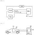
- the conventional electric vehicle further includes a fuse 110 between internal control parts (ECU, etc.), and detects a failure occurrence by opening the fuse part when a failure mode attributable an overcurrent occurs.
- ECU internal control parts
- an object of the present invention is to provide a circuit failure detector capable of detecting a circuit failure through two types of output signals using a first comparator and a second comparator and differentially detecting various failure modes.
- a circuit failure detector for achieving the objects may include an input terminal receiving a detection signal having a first frequency from an interlock circuit; a correction circuit correcting a voltage of the input detection signal by adding an offset voltage to a voltage of the input detection signal; a first comparator outputting a high voltage signal or a low voltage signal by comparing the corrected detection signal with a first reference voltage; a second comparator inverting the corrected detection signal and outputting a high voltage signal or a low voltage signal by comparing the inverted detection signal with a second reference voltage; a counting signal generator generating a counting signal having a second frequency; a first coupler coupling the output signal of the first comparator and the counting signal; a second coupler coupling the output signal of the second comparator and the counting signal; and a controller detecting a circuit failure based on an output signal of the first coupler and an output signal of the second coupler.
- the controller may detect that the interlock circuit is a normal state when the output signal of
- the controller may detect that the interlock circuit is a circuit failure of an open state when the output signal of the first coupler and the output signal of the second coupler are low voltage signals.
- the controller may detect that the interlock circuit is a circuit failure of a battery-short state when an output signal of the first coupler is a preset value or more and an output signal of the second coupler is a low voltage signal.
- the controller may detect that the interlock circuit is a circuit failure of a ground (GND)-short state when the output signal of the first coupler is a low voltage signal and the output signal of the second coupler is a preset value or more.
- GND ground
- the controller may detect that the interlock circuit is a failure when the second frequency of the output signal of the first coupler or the output signal of the second coupler exceeds a preset range.
- the circuit failure detector may further include a given detection signal generator generating a given detection signal having the first frequency and inputting the given detection signal to the input terminal.
- the controller may detect a circuit failure based on the output signal of the first coupler or output signal of the second coupler generated based on the given detection signal.
- a circuit failure detection method using a circuit failure detector including an input terminal, a correction circuit, a first comparator, a second comparator, a counting signal generator, a first coupler, a second coupler and a controller may include the steps of (a) inputting a detection signal having a first frequency from an interlock circuit to the input terminal; (b) correcting, by the correction circuit, a voltage of the detection signal by adding an offset voltage to a voltage of the input detection signal; (c) comparing, by the first comparator, the corrected detection signal with a first reference voltage and outputting a high voltage signal or a low voltage signal; (d) inverting, by the second comparator, the corrected detection signal, comparing the inverted detection signal with a second reference voltage, and outputting a high voltage signal or a low voltage signal; (e) generating, by the counting signal generator, a counting signal having a second frequency; (f) coupling, by the first coupler, the output signal of the first comparator and the counting signal;
- the interlock circuit in the step (h), may be detected as being a normal state when the output signal of the first coupler and the output signal of the second coupler are preset values or more.
- the interlock circuit in the step (h), the interlock circuit may be detected as being a circuit failure of an open state when the output signal of the first coupler and the output signal of the second coupler are low voltage signals.
- the interlock circuit in the step (h), may be detected as being a circuit failure of a battery-short state when an output signal of the first coupler is a preset value or more and an output signal of the second coupler is a low voltage signal.
- the interlock circuit in the step (h), may be detected as being a circuit failure of a ground (GND)-short state when the output signal of the first coupler is a low voltage signal and the output signal of the second coupler is a preset value or more.
- GND ground
- the interlock circuit in the step (h), may be detected as being a failure when a second frequency of an output signal of the first coupler or output signal of the second coupler exceeds a preset range.
- An electric vehicle charging controller includes a circuit failure detector; a power connector receiving power from an electric vehicle charging station; a relay circuit connected to the power connector; and a power supply circuit connected to the relay circuit to supply power to a battery of an electric vehicle.
- the circuit failure detector includes an input terminal receiving a detection signal having a first frequency from an interlock circuit; a correction circuit correcting a voltage of the input detection signal; a first comparator outputting a high voltage signal or a low voltage signal by comparing the corrected detection signal with a first reference voltage; a second comparator inverting the corrected detection signal and outputting a high voltage signal or a low voltage signal by comparing the inverted detection signal with a second reference voltage; a counting signal generator generating a counting signal having a second frequency; a first coupler coupling the output signal of the first comparator and the counting signal; a second coupler coupling the output signal of the second comparator and the counting signal; and a controller detecting a circuit failure based on an output signal of the first coupler and an output signal of the second coupler.
- the switch of the relay circuit may be open.
- the circuit failure detector of the present invention and the electric vehicle charging controller including the same can receive a detection signal to detect a closed loop state in the charging or discharging process of an electric vehicle, and can detect a failure mode of the electric vehicle by identifying an output signal of the coupler coupled to the output signals of the first comparator and the second comparator to be four states.
- circuit failure detector of the present invention and the electric vehicle charging controller including the same can differentially detect failure modes of four states of a normal state, a battery-short state, a GND-short state, and an open state.
- circuit failure detector of the present invention and the electric vehicle charging controller including the same can provide convenience of failure diagnosis because they can distinguish between the failure modes.
- the circuit failure detector of the present invention and the electric vehicle charging controller including the same can detect a failure mode for an HVIL signal loss by autonomously generating a given detection signal without receiving a detection signal generated by an electric vehicle.
- the circuit failure detector of the present invention and the electric vehicle charging controller including the same can reduce a failure repair cost compared to a disposable fuse because a separate controller is included without using a fuse and the controller opens a relay circuit when detecting a circuit failure. Furthermore, when a failure mode returns to a normal mode, a normal operation can be performed without separate measures even without a loss of a related part (fuse, etc.).
- circuit failure detector of the present invention and the electric vehicle charging controller including the same can reduce a failure itself because a circuit configuration is simple.
- circuit failure detector of the present invention and the electric vehicle charging controller including the same do not require a separate design change according to a signal configuration of an electric vehicle, and may be configured in a module-independent form and an electric vehicle association form and mounted and used.
- each layer (or film), area, pattern or structure is formed “over/on” or “under/below” each substrate, layer (or film), area, pad or structure, this includes both expressions, including that one element is directly formed on the other element and that a third element is interposed between the two elements.
- a criterion for the term “over/on” or “under/below” of each layer is described based on the drawings.
- one part When it is described that one part is “connected” to the other part, the one part may be “directly connected” to the other part or may be “indirectly connected” to the other part through a third part. Furthermore, when it is said that one part "includes” the other part, the word “include (or comprise)” will be understood to imply the inclusion of stated parts but not the exclusion of any other parts, unless explicitly described to the contrary.
- FIG. 2 relates to the configuration of a circuit failure detector and an electric vehicle according to an embodiment of the present invention.
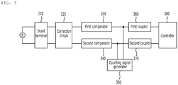
- FIG. 3 relates to the configuration of a circuit failure detector according to an embodiment of the present invention.
- the electric vehicle 210 when the electric vehicle 210 is connected to a charging station 220 and performs charging or discharging, power or a voltage supplied by the charging station 220 is applied to various parts (inverter, motor, PDU, insulation protector, charging battery) included in the electric vehicle 210 without any change.
- the parts included in the electric vehicle may include various complicated circuits. Accordingly, when an overvoltage or an overcurrent is applied to the circuits, there is a danger that an overall operation of the electric vehicle may be stopped.
- the circuit failure detector determines a circuit failure by detecting the state of a voltage applied to several portions of various electronic parts included in the electric vehicle. More specifically, the circuit failure detector of the present invention is preferably positioned within the electric vehicle, and can prevent a failure mode of the electric vehicle under the control of an electric vehicle charging controller. The circuit failure detector is connected to a relay circuit and protects the parts of the electric vehicle by opening a closed loop circuit.
- FIG. 4 relates to the circuit diagram of the circuit failure detector according to an embodiment of the present invention.
- the circuit failure detector of the present invention may include an input terminal 310, a correction circuit 320, a first comparator 330, a second comparator 340, a counting signal generator 350, a first coupler 360, a second coupler 370, and a controller 380.
- the input terminal 310 may receive a detection signal having a first frequency from an interlock circuit.
- various failure modes such as a movement of the vehicle, the abnormality of a charging station, and damage to a circuit within the vehicle, may occur in a connection state with the charging station.
- the electric vehicle may include the interlock circuit in order to prevent a loss of the electric vehicle occurring due to such failure modes.
- the interlock circuit may generate a detection signal having a first frequency by detecting the state of several parts of the electric vehicle.
- a detection signal includes a pulse width modulation (PWM) signal, and may be represented by modulating various states through the conversion of a duty. More specifically, the detection signal may have a square wave having a first frequency 88Hz and a duty 50%.
- PWM pulse width modulation
- the detection signal input to the input terminal passes through the correction circuit, the comparators, and the couplers, so a failure mode can be determined based on an output signal.
- the correction circuit 320 may correct a voltage of an input detection signal. If the detection signal is used without any change, an error of the corresponding detection signal may not be properly measured in the comparator or the controller.
- the correction circuit of the present invention corrects a voltage of the detection signal so that a circuit failure is easily detected, and uses the corrected signal.
- the correction circuit 320 of the present invention may correct the voltage of the input detection signal by adding an offset voltage to the voltage.
- the correction circuit 320 may correct the detection signal using a battery voltage because the battery voltage swings between 9 ⁇ 16 V. Accordingly, the correction circuit of the present invention can correct an input detection signal into a preset square wave by offsetting the input detection signal to a battery voltage or a given setting voltage.
- the correction circuit 320 of the present invention may include an operational amplifier for receiving a battery voltage adjusted to a given value based on a voltage distribution, an operational amplifier for receiving the output value of the operational amplifier and a detection signal applied by the input terminal, multiple resistors for adjusting other voltage values, capacitors for charging, noise elimination and the stabilization of a circuit, and so on.
- the comparator is a circuit for comparing one voltage with the other voltage, and is a device for receiving an input voltage, detecting whether the input voltage exceeds a reference voltage by comparing the input voltage with the reference voltage, and outputting the results of the comparison as a digital (low, high) value. Furthermore, the comparator of the present invention may compare the size of the input voltage with the size of the reference voltage and output one of the input voltage and the reference voltage.
- the first comparator 330 of the present invention may compare a corrected detection signal with a first reference voltage and output a high voltage signal or a low voltage signal. Furthermore, the second comparator 340 of the present invention may invert the corrected detection signal, may compare the inverted detection signal with a second reference voltage, and may output a high voltage signal or a low voltage signal.
- the first comparator 330 and second comparator 340 of the present invention may include an operational amplifier for receiving a corrected detection signal and comparing the received detection signal with a first reference voltage, multiple resistors for generating a voltage adjusted to a given value based on a voltage distribution, capacitors for charging, noise elimination and the stabilization of a circuit, and so on.
- each of the first comparator 330 and the second comparator 340 receives an inverted signal and compares the inverted single with a reference voltage.
- a corrected detection signal input to the first comparator is applied to the (+) input terminal of the operational amplifier
- a corrected detection signal input to the second comparator is applied to the (-) input terminal of the operational amplifier. Accordingly, signals output by the first comparator and the second comparator have inverted values, so circuit failures having failure modes of different states can be effectively identified based on the output signal values.
- the first reference voltage of the first comparator of the present invention may be lower than the second reference voltage of the second comparator.
- an output signal may be generated using the second reference voltage lower than the first reference voltage because a detection signal applied to the first comparator is inverted and applied to the second comparator.
- a resistor connected to the operational amplifier may be configured so that the first reference voltage of the present invention has a 2/3 size of a battery voltage.
- a resistor connected to the operational amplifier may be configured so that the second reference voltage has a 1/3 size of a battery voltage.
- the first comparator 330 of the present invention may output the corrected detection signal when the corrected detection signal is higher than the first reference voltage.
- the second comparator 340 of the present invention may output the inverted detection signal when the inverted detection signal is lower than the second reference voltage.
- the comparator 330, 340 of the present invention may output a high voltage signal (High) or a low voltage signal (Low) depending on the + or - of a compared value when the value is compared with a reference voltage. However, when the value is higher or lower than the reference voltage, the comparator may output a corresponding input signal without any change. Accordingly, the first comparator and second comparator of the present invention may output a corrected detection signal received after it is compared with a reference voltage.
- the counting signal generator 350 may generate a counting signal having a second frequency.
- the counting signal is coupled with a detection signal by the coupler so that the controller detects a circuit failure based on the final output signal.
- a circuit failure may be detected using only a detection signal.
- various states may not be differentially determined because an output signal has only a high voltage (High) or low voltage (Low) state value.
- the circuit failure detector of the present invention further includes the counting signal generator 350, and thus can effectively detect a circuit failure based on a detection signal coupled with a counting signal.
- the second frequency of the counting signal may be higher than the first frequency.
- the second frequency of the present invention may be a frequency of about 10 kHz, and the first frequency may have a frequency of 88 Hz.
- the first coupler 360 may couple the output signal of the first comparator 330 and the counting signal.
- the second coupler 370 may couple the output signal of the second comparator 340 and the counting signal.
- the final output signal having the first frequency and the second frequency may be generated by coupling a signal output by the comparator 330, 340 and the counting signal.
- the coupler 360, 370 may include an AND gate.
- FIGS. 5a and 5b the final output signal of a detection signal coupled with a counting signal may be seen.
- the scale of the horizontal axis (time) of FIG. 5a is expanded and viewed, it may be seen that 1/0/1/0 states alternate like the second frequency of the counting signal during the high period of the first frequency of the detection signal.
- the controller 380 may detect a circuit failure based on the output signal of the first coupler 360 and the output signal of the second coupler 370. More specifically, the controller detect the output signal of the first coupler 360 and the output signal of the second coupler 370, and determines whether a circuit has fails by identifying the state of a corresponding output signal. In this case, the controller detects a circuit failure by detecting the output signal of the first coupler 360 as a high state and the output signal of the second coupler 370 as a low state.
- the controller 380 of the present invention may detect that the interlock circuit is a normal state when the output signal of the first coupler 360 and the output signal (e.g., pulse count, FIG. 5b ) of the second coupler 370 is a preset value or more.
- the controller 380 of the present invention may identify that the output signal of the first coupler and the output signal of the second coupler normally have a given value (high value) or more, and may detect that the interlock circuit is a normal state.
- controller 380 of the present invention couples and counts the signals of a higher frequency in order to identify that the high and low signals of FIG. 5a are alternated.
- the controller 380 of the present invention may detect a circuit failure by counting the output signal (highside pulse of FIG. 5b ) of the first coupler 360 and counting the output signal (low-side pulse of FIG. 5b ) of the second coupler 370.
- the controller may identify whether an input signal of a normal duty is received by counting the number of pulses.
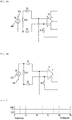
- FIGS. 6a and 6b relate to circuit diagrams for the open state of an electric vehicle according to another embodiment of the present invention.
- FIG. 7 is a graph of the output signal of the circuit failure detector in the open state of an electric vehicle according to another embodiment of the present invention.
- the controller 380 of the present invention may detect that the interlock circuit is a circuit failure of an open state when the output signal of the first coupler and the output signal of the second coupler are low voltage signals.
- an open state When the interlock circuit is an open state, this means that a detection signal 400 applied by the interlock circuit is not connected to any one of both input terminals.
- An overall open state 410, 420 of an electric vehicle may be represented as the circuit of FIG. 6a or 6b . It may be said that a failure mode of an open state has occurred in a part that belongs to various parts of an electric vehicle and that is detected by the circuit failure detector of the present invention.
- the states of the output signal of the first coupler 360 and the output signal of the second coupler 370 of the present invention may be seen when the interlock circuit is an open state.
- the detection signal 400 is no longer input to the input terminal of the interlock circuit.
- both the first coupler and the second coupler output a low voltage signal 0.
- the controller of the present invention may detect that the parts of an electric vehicle are an open state by detecting that all the output signals have low voltage signals.
- FIGS. 8a and 8b relate to the circuit diagrams for the battery-short state of an electric vehicle according to another embodiment of the present invention.
- FIG. 9 is a graph of an output signal of the circuit failure detector in the battery-short state of an electric vehicle according to another embodiment of the present invention.
- the controller of the present invention may detect that the interlock circuit is a circuit failure of a battery-short state when the output signal of the first coupler is a preset value or more and the output signal of the second coupler is a low voltage signal.
- the interlock circuit is positioned within an electric vehicle, and thus may be the battery-short state in which the power input node 510 of a battery 500 and the interlock circuit 410, 420 are short-circuited.
- an overall battery-short state of the electric vehicle may be represented as the circuit of FIG. 8a or 8b .
- a part that belongs to various parts included in the electric vehicle and that is detected by the circuit failure detector of the present invention is a failure mode of the battery-short state in which the part and the battery are shorted.
- the output signal of the first coupler and the output signal of the second coupler of the present invention may be seen when the interlock circuit is the battery-short state.
- the first coupler outputs a high state of a preset value or more, and thus the second coupler outputs a low voltage signal 0.
- the controller of the present invention may detect that a part of an electric vehicle is the battery-short state by detecting the output signals of the first coupler and the second coupler.
- FIGS. 10a and 10b relate to the circuit diagrams of the GND-short state of an electric vehicle according to another embodiment of the present invention.
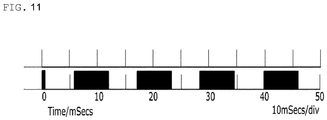
- FIG. 11 is a graph of am output signal of the circuit failure detector in the GND-short state of an electric vehicle according to another embodiment of the present invention.
- the controller of the present invention may detect that the interlock circuit is a circuit failure of a ground (GND)-short state when the output signal of the first coupler is a low voltage signal and the output signal of the second coupler is a preset value or more.
- GND ground
- the interlock circuit is positioned within an electric vehicle, and thus may be the GND-short state in which a ground 520 and the interlock circuit are short-circuited. Specifically, in the case of a vehicle, such a failure mode may occur when part of the interlock circuit comes into contact with a vehicle body because the vehicle body itself made of metal functions as the ground.
- an overall GND-short state of an electric vehicle may be represented as the circuit of FIG. 10a or 10b . Accordingly, it may be said that a part that belongs to various parts included in the electric vehicle and that is detected by the circuit failure detector of the present invention has a failure mode of the GND-short state in which the part and the ground are shorted.
- the output signal of the first coupler and output signal of the second coupler of the present invention may be seen when the interlock circuit is the GND-short state.
- the first coupler outputs a low voltage signal 0, and the second coupler outputs a preset value or more (High).
- the controller of the present invention may detect that a part of an electric vehicle is the GND-short state by detecting the output signals of the first coupler and the second coupler.
- the controller 380 of the present invention may detect that the interlock circuit is a failure when the second frequency of the output signal of the first coupler 360 or the output signal of the second coupler 370 exceeds a preset range.
- a detection signal input to the input terminal of the present invention may be coupled with a counting signal to generate the final output signal.
- the second frequency of the final output signal needs to be constantly output as in FIG. 5b .
- abnormality when a part included in an electric vehicle or the counting signal generator itself is abnormal, abnormality may occur in the second frequency. More specifically, 55 times of highs/lows may alternately occur in the high state of the first frequency. However, when the part or the counting signal generator is abnormal, frequency abnormality in which 40 times or 100 times of highs/lows alternately occur may occur.
- the controller of the present invention may identify a failure mode of the electric vehicle by detecting the second frequency.
- the circuit failure detector of the present invention may further include a given detection signal generator.
- the given detection signal generator may generate a given detection signal having a first frequency and input the given detection signal to the input terminal.
- the controller of the present invention may detect a circuit failure based on the output signal of the first coupler or the output signal of the second coupler generated based on the given detection signal.
- the circuit failure detector of the present invention can autonomously generate a detection signal, and may detect a failure mode when the detection signal itself of the input terminal is damaged. Furthermore, the circuit failure detector can efficiently detect a failure mode of a vehicle part using a given detection signal without receiving a signal from the vehicle.
- the circuit failure detector of the present invention may be used in an electric vehicle charging controller 211 and may also be included in the electric vehicle 210.
- the electric vehicle charging controller 211 includes a circuit failure detector, a power connector for receiving power from an electric vehicle charging station, a relay circuit connected to the power connector, and a power supply circuit connected to the relay circuit to supply power to the battery of an electric vehicle.
- the circuit failure detector includes the input terminal receiving a detection signal having a first frequency from the interlock circuit, the correction circuit correcting a voltage of the input detection signal, the first comparator outputting a high voltage signal or a low voltage signal by comparing the corrected detection signal with a first reference voltage, the second comparator inverting the corrected detection signal and outputting a high voltage signal or a low voltage signal by comparing the inverted detection signal with a second reference voltage, the counting signal generator generating a counting signal having a second frequency, the first coupler coupling the output signal of the first comparator and the counting signal, the second coupler coupling the output signal of the second comparator and the counting signal, and the controller detecting a circuit failure based on the output signal of the first coupler and the output signal of the second coupler.
- the circuit failure detector may open the switch of the relay circuit.
- the above-described circuit failure detector determines only a failure of a circuit included in an electric vehicle, and the configuration of additional measures according to a circuit failure may be implemented by the electric vehicle charging controller.
- the electric vehicle charging controller of the present invention may include the circuit failure failure detector, the power connector, the relay circuit, the power supply circuit.
- the power connector may receive the power and supply the power to the battery of the electric vehicle through the power supply circuit.
- the electric vehicle charging controller of the present invention further includes the relay circuit, and converts the electric vehicle into a safety state by opening the switch of the relay circuit when the controller detects a circuit failure.
- the electric vehicle 210 includes an interlock circuit, a circuit failure detector, a power connector receiving power from an electric vehicle charging station, a relay circuit connected to the power connector, and a power supply circuit connected to the relay circuit to supply power to the battery of an electric vehicle.
- the power connector includes a power input port and an interlock port.
- the interlock circuit includes a detection signal generator generating a detection signal having a first frequency, at least one electronic part included in the electric vehicle, and a detection wire connected to the interlock port and the detection signal generator to form a closed loop.
- the circuit failure detector includes the input terminal receiving a detection signal having a first frequency from the interlock circuit, the correction circuit correcting a voltage of the input detection signal, the first comparator outputting a high voltage signal or a low voltage signal by comparing the corrected detection signal with a first reference voltage, the second comparator inverting the corrected detection signal and outputting a high voltage signal or a low voltage signal by comparing the inverted detection signal with a second reference voltage, the counting signal generator generating a counting signal having a second frequency, the first coupler coupling the output signal of the first comparator and the counting signal, the second coupler coupling the output signal of the second comparator and the counting signal, and the controller detecting a circuit failure based on the output signal of the first coupler and the output signal of the second coupler.
- the circuit failure detector may open the switch of the relay circuit.
- the electric vehicle may include various parts, and may include a detection wire connected to a corresponding part, the interlock port and the detection signal generator to form a closed loop.
- the circuit failure detector of the present invention may identify the charging state of the electric vehicle through the detection wire, and may identify a failure mode as in the above-described control method of the electric vehicle charging controller and implement it as the safety state of the electric vehicle through open control of the relay circuit.
- the electric vehicle charging controller and the circuit failure detector included in the electric vehicle may be implemented to include all the elements and functions of the above-described circuit failure detector.
Landscapes
- Engineering & Computer Science (AREA)
- Physics & Mathematics (AREA)
- General Physics & Mathematics (AREA)
- Power Engineering (AREA)
- Transportation (AREA)
- Mechanical Engineering (AREA)
- Life Sciences & Earth Sciences (AREA)
- Sustainable Development (AREA)
- Sustainable Energy (AREA)
- Combustion & Propulsion (AREA)
- Chemical & Material Sciences (AREA)
- Computer Hardware Design (AREA)
- Microelectronics & Electronic Packaging (AREA)
- Electric Propulsion And Braking For Vehicles (AREA)
- Charge And Discharge Circuits For Batteries Or The Like (AREA)
- Testing Of Short-Circuits, Discontinuities, Leakage, Or Incorrect Line Connections (AREA)
Abstract
Description
- The present invention relates to a circuit failure detector, including an input terminal receiving a detection signal having a first frequency from an interlock circuit, a correction circuit correcting a voltage of the input detection signal, a first comparator outputting a high voltage signal or a low voltage signal by comparing the corrected detection signal with a first reference voltage, a second comparator inverting the corrected detection signal and outputting a high voltage signal or a low voltage signal by comparing the inverted detection signal with a second reference voltage, a counting signal generator generating a counting signal having a second frequency, a first coupler coupling the output signal of the first comparator and the counting signal, a second coupler coupling the output signal of the second comparator and the counting signal, and a controller detecting a circuit failure based on an output signal of the first coupler and an output signal of the second coupler.
- An electric vehicle is a vehicle obtaining driving energy of the vehicle from electric energy not by the combustion of fossil fuel. Such an electric vehicle has excellent no-pollution and eco-friendly advantages because it absolutely has no exhaust gas and has very small noise. However, the electric vehicle essentially requires a battery, that is, the supply source of energy, and the commercialization of the electric vehicle is delayed due to the light-weight/small size and short charging time of the battery.
- Meanwhile, for the infrastructure construction of the electric vehicle, charging stations must be installed nationwide. Like a conventional gas station used by a vehicle, the charging station can supply a power source to a battery, that is, the energy source of the electric vehicle. Recently many charging stations are deployed along the rapid supply of electric vehicles.
- In this case, if the electric vehicle is connected to the charging station and performs charging or discharging, a charging closed loop generated in the charging or discharging process may be formed. Through the charging closed loop, the charging station may supply power to the electric vehicle and the electric vehicle may be discharged toward the charging station.
- However, in the process of the electric vehicle being charged or discharged in the charging station, various failure modes, such as a short, an open, a short circuit, a battery short and a ground (vehicle body) short, may occur. Referring to
FIG. 1 , in the case of a conventional electric vehicle, a one-way loop interrupt detection method is used to detect a failure mode. - Furthermore, referring to
FIG. 1 , the conventional electric vehicle further includes afuse 110 between internal control parts (ECU, etc.), and detects a failure occurrence by opening the fuse part when a failure mode attributable an overcurrent occurs. - In such a conventional failure mode processing method, however, there is inconvenience that a fuse must be replaced each time because the fuse is open when a failure mode occurs. There is a problem in that a failure mode cannot be detected when an overcurrent does not flow to the extent that the fuse is suspended. Furthermore, there is a disadvantage in that failure diagnosis cannot be performed although a failure occurs in a high-voltage interlock (HVIL) module itself.
- In order to solve the disadvantages of a conventional electric vehicle failure mode detector as described above, an object of the present invention is to provide a circuit failure detector capable of detecting a circuit failure through two types of output signals using a first comparator and a second comparator and differentially detecting various failure modes.
- Technical objects to be achieved by the present invention are not limited to the above-described objects, and may include various technical objects within the range evident to those skilled in the art from the following description.
- A circuit failure detector according to an embodiment of the present invention for achieving the objects may include an input terminal receiving a detection signal having a first frequency from an interlock circuit; a correction circuit correcting a voltage of the input detection signal by adding an offset voltage to a voltage of the input detection signal; a first comparator outputting a high voltage signal or a low voltage signal by comparing the corrected detection signal with a first reference voltage; a second comparator inverting the corrected detection signal and outputting a high voltage signal or a low voltage signal by comparing the inverted detection signal with a second reference voltage; a counting signal generator generating a counting signal having a second frequency; a first coupler coupling the output signal of the first comparator and the counting signal; a second coupler coupling the output signal of the second comparator and the counting signal; and a controller detecting a circuit failure based on an output signal of the first coupler and an output signal of the second coupler. In one embodiment of the present invention, the controller may detect that the interlock circuit is a normal state when the output signal of the first coupler and the output signal of the second coupler are preset values or more.
- In one embodiment of the present invention, the controller may detect that the interlock circuit is a circuit failure of an open state when the output signal of the first coupler and the output signal of the second coupler are low voltage signals.
- In one embodiment of the present invention, the controller may detect that the interlock circuit is a circuit failure of a battery-short state when an output signal of the first coupler is a preset value or more and an output signal of the second coupler is a low voltage signal.
- In one embodiment of the present invention, the controller may detect that the interlock circuit is a circuit failure of a ground (GND)-short state when the output signal of the first coupler is a low voltage signal and the output signal of the second coupler is a preset value or more.
- In one embodiment of the present invention, the controller may detect that the interlock circuit is a failure when the second frequency of the output signal of the first coupler or the output signal of the second coupler exceeds a preset range.
- Furthermore, the circuit failure detector according to an embodiment of the present invention may further include a given detection signal generator generating a given detection signal having the first frequency and inputting the given detection signal to the input terminal.
- In one embodiment of the present invention, the controller may detect a circuit failure based on the output signal of the first coupler or output signal of the second coupler generated based on the given detection signal.
- A circuit failure detection method using a circuit failure detector including an input terminal, a correction circuit, a first comparator, a second comparator, a counting signal generator, a first coupler, a second coupler and a controller according to another embodiment of the present invention may include the steps of (a) inputting a detection signal having a first frequency from an interlock circuit to the input terminal; (b) correcting, by the correction circuit, a voltage of the detection signal by adding an offset voltage to a voltage of the input detection signal; (c) comparing, by the first comparator, the corrected detection signal with a first reference voltage and outputting a high voltage signal or a low voltage signal; (d) inverting, by the second comparator, the corrected detection signal, comparing the inverted detection signal with a second reference voltage, and outputting a high voltage signal or a low voltage signal; (e) generating, by the counting signal generator, a counting signal having a second frequency; (f) coupling, by the first coupler, the output signal of the first comparator and the counting signal; (g) coupling, by the second coupler, the output signal of the second comparator and the counting signal; and (h) detecting, by the controller, a circuit failure based on an output signal of the first coupler and an output signal of the second coupler.
- In the circuit failure detection method according to an embodiment of the present invention, in the step (h), the interlock circuit may be detected as being a normal state when the output signal of the first coupler and the output signal of the second coupler are preset values or more.
- In the circuit failure detection method according to an embodiment of the present invention, in the step (h), the interlock circuit may be detected as being a circuit failure of an open state when the output signal of the first coupler and the output signal of the second coupler are low voltage signals.
- In the circuit failure detection method according to an embodiment of the present invention, in the step (h), the interlock circuit may be detected as being a circuit failure of a battery-short state when an output signal of the first coupler is a preset value or more and an output signal of the second coupler is a low voltage signal.
- In the circuit failure detection method according to an embodiment of the present invention, in the step (h), the interlock circuit may be detected as being a circuit failure of a ground (GND)-short state when the output signal of the first coupler is a low voltage signal and the output signal of the second coupler is a preset value or more.
- In the circuit failure detection method according to an embodiment of the present invention, in the step (h), the interlock circuit may be detected as being a failure when a second frequency of an output signal of the first coupler or output signal of the second coupler exceeds a preset range.
- An electric vehicle charging controller according to yet another embodiment of the present invention includes a circuit failure detector; a power connector receiving power from an electric vehicle charging station; a relay circuit connected to the power connector; and a power supply circuit connected to the relay circuit to supply power to a battery of an electric vehicle. The circuit failure detector includes an input terminal receiving a detection signal having a first frequency from an interlock circuit; a correction circuit correcting a voltage of the input detection signal; a first comparator outputting a high voltage signal or a low voltage signal by comparing the corrected detection signal with a first reference voltage; a second comparator inverting the corrected detection signal and outputting a high voltage signal or a low voltage signal by comparing the inverted detection signal with a second reference voltage; a counting signal generator generating a counting signal having a second frequency; a first coupler coupling the output signal of the first comparator and the counting signal; a second coupler coupling the output signal of the second comparator and the counting signal; and a controller detecting a circuit failure based on an output signal of the first coupler and an output signal of the second coupler. When the controller detects a circuit failure, the switch of the relay circuit may be open.
- The circuit failure detector of the present invention and the electric vehicle charging controller including the same can receive a detection signal to detect a closed loop state in the charging or discharging process of an electric vehicle, and can detect a failure mode of the electric vehicle by identifying an output signal of the coupler coupled to the output signals of the first comparator and the second comparator to be four states.
- Furthermore, the circuit failure detector of the present invention and the electric vehicle charging controller including the same can differentially detect failure modes of four states of a normal state, a battery-short state, a GND-short state, and an open state.
- Furthermore, the circuit failure detector of the present invention and the electric vehicle charging controller including the same can provide convenience of failure diagnosis because they can distinguish between the failure modes.
- Furthermore, the circuit failure detector of the present invention and the electric vehicle charging controller including the same can detect a failure mode for an HVIL signal loss by autonomously generating a given detection signal without receiving a detection signal generated by an electric vehicle.
- Furthermore, the circuit failure detector of the present invention and the electric vehicle charging controller including the same can reduce a failure repair cost compared to a disposable fuse because a separate controller is included without using a fuse and the controller opens a relay circuit when detecting a circuit failure. Furthermore, when a failure mode returns to a normal mode, a normal operation can be performed without separate measures even without a loss of a related part (fuse, etc.).
- Furthermore, the circuit failure detector of the present invention and the electric vehicle charging controller including the same can reduce a failure itself because a circuit configuration is simple.
- Furthermore, the circuit failure detector of the present invention and the electric vehicle charging controller including the same do not require a separate design change according to a signal configuration of an electric vehicle, and may be configured in a module-independent form and an electric vehicle association form and mounted and used.
-
-
FIG. 1 relates to an embodiment of a conventional electric vehicle failure mode prevention circuit. -
FIG. 2 relates to the configuration of a circuit failure detector and an electric vehicle according to an embodiment of the present invention. -
FIG. 3 relates to the configuration of a circuit failure detector according to an embodiment of the present invention. -
FIG. 4 relates to the circuit diagram of the circuit failure detector according to an embodiment of the present invention. -
FIGS. 5a and 5b are graphs of an output signal for the normal state of the circuit failure detector according to an embodiment of the present invention. -
FIGS. 6a and 6b relate to circuit diagrams for the open state of an electric vehicle according to another embodiment of the present invention. -
FIG. 7 is a graph of the output signal of the circuit failure detector in the open state of an electric vehicle according to another embodiment of the present invention. -
FIGS. 8a and8b relate to the circuit diagrams for the battery-short state of an electric vehicle according to another embodiment of the present invention. -
FIG. 9 is a graph of an output signal of the circuit failure detector in the battery-short state of an electric vehicle according to another embodiment of the present invention. -
FIGS. 10a and10b relate to the circuit diagrams of the GND-short state of an electric vehicle according to another embodiment of the present invention. -
FIG. 11 is a graph of am output signal of the circuit failure detector in the GND-short state of an electric vehicle according to another embodiment of the present invention. - Hereinafter, a "circuit failure detector and an electric vehicle charging controller including the same" according to the present invention are described in detail with reference to the accompanying drawings. The embodiments are provided so that those skilled in the art may easily understand the technical spirit of the present invention and the present invention is not restricted by the embodiments. Furthermore, contents described in the accompanying drawings have been diagrammed in order to easily describe the embodiments of the present invention, and may be different from forms that are actually implemented.
- Elements to be described herein are only examples for implementing the embodiments of the present invention. Accordingly, in other implementations of the present invention, different elements may be used without departing from the spirit and scope of the present invention.
- Furthermore, an expression that some elements are "included" is an expression of an "open type", and the expression simply denotes that the corresponding elements are present, but should not be construed as excluding additional elements.
- Furthermore, expressions, such as "the first" and "the second", are used to only distinguish between a plurality of elements and do not limit the sequence or other characteristics of the elements.
- In the description of the present invention, when it is said that each layer (or film), area, pattern or structure is formed "over/on" or "under/below" each substrate, layer (or film), area, pad or structure, this includes both expressions, including that one element is directly formed on the other element and that a third element is interposed between the two elements. A criterion for the term "over/on" or "under/below" of each layer is described based on the drawings.
- When it is described that one part is "connected" to the other part, the one part may be "directly connected" to the other part or may be "indirectly connected" to the other part through a third part. Furthermore, when it is said that one part "includes" the other part, the word "include (or comprise)" will be understood to imply the inclusion of stated parts but not the exclusion of any other parts, unless explicitly described to the contrary.
-
FIG. 2 relates to the configuration of a circuit failure detector and an electric vehicle according to an embodiment of the present invention.FIG. 3 relates to the configuration of a circuit failure detector according to an embodiment of the present invention. - Referring to
FIGS. 2 and3 , when theelectric vehicle 210 is connected to a chargingstation 220 and performs charging or discharging, power or a voltage supplied by the chargingstation 220 is applied to various parts (inverter, motor, PDU, insulation protector, charging battery) included in theelectric vehicle 210 without any change. Specifically, the parts included in the electric vehicle may include various complicated circuits. Accordingly, when an overvoltage or an overcurrent is applied to the circuits, there is a danger that an overall operation of the electric vehicle may be stopped. - The circuit failure detector according to an embodiment of the present invention determines a circuit failure by detecting the state of a voltage applied to several portions of various electronic parts included in the electric vehicle. More specifically, the circuit failure detector of the present invention is preferably positioned within the electric vehicle, and can prevent a failure mode of the electric vehicle under the control of an electric vehicle charging controller. The circuit failure detector is connected to a relay circuit and protects the parts of the electric vehicle by opening a closed loop circuit.
-
FIG. 4 relates to the circuit diagram of the circuit failure detector according to an embodiment of the present invention. - Referring to
FIGS. 3 and4 , the circuit failure detector of the present invention may include aninput terminal 310, acorrection circuit 320, afirst comparator 330, asecond comparator 340, acounting signal generator 350, afirst coupler 360, asecond coupler 370, and acontroller 380. - The
input terminal 310 may receive a detection signal having a first frequency from an interlock circuit. In an electric vehicle, various failure modes, such as a movement of the vehicle, the abnormality of a charging station, and damage to a circuit within the vehicle, may occur in a connection state with the charging station. The electric vehicle may include the interlock circuit in order to prevent a loss of the electric vehicle occurring due to such failure modes. - In this case, the interlock circuit may generate a detection signal having a first frequency by detecting the state of several parts of the electric vehicle. Furthermore, such a detection signal includes a pulse width modulation (PWM) signal, and may be represented by modulating various states through the conversion of a duty. More specifically, the detection signal may have a square wave having a first frequency 88Hz and a
duty 50%. - The detection signal input to the input terminal passes through the correction circuit, the comparators, and the couplers, so a failure mode can be determined based on an output signal.
- The
correction circuit 320 may correct a voltage of an input detection signal. If the detection signal is used without any change, an error of the corresponding detection signal may not be properly measured in the comparator or the controller. The correction circuit of the present invention corrects a voltage of the detection signal so that a circuit failure is easily detected, and uses the corrected signal. - More specifically, the
correction circuit 320 of the present invention may correct the voltage of the input detection signal by adding an offset voltage to the voltage. In the case of a battery included in an electric vehicle in which the circuit failure detector of the present invention is positioned, thecorrection circuit 320 may correct the detection signal using a battery voltage because the battery voltage swings between 9 ∼ 16 V. Accordingly, the correction circuit of the present invention can correct an input detection signal into a preset square wave by offsetting the input detection signal to a battery voltage or a given setting voltage. - More specifically, the
correction circuit 320 of the present invention may include an operational amplifier for receiving a battery voltage adjusted to a given value based on a voltage distribution, an operational amplifier for receiving the output value of the operational amplifier and a detection signal applied by the input terminal, multiple resistors for adjusting other voltage values, capacitors for charging, noise elimination and the stabilization of a circuit, and so on. - The comparator is a circuit for comparing one voltage with the other voltage, and is a device for receiving an input voltage, detecting whether the input voltage exceeds a reference voltage by comparing the input voltage with the reference voltage, and outputting the results of the comparison as a digital (low, high) value. Furthermore, the comparator of the present invention may compare the size of the input voltage with the size of the reference voltage and output one of the input voltage and the reference voltage.
- The
first comparator 330 of the present invention may compare a corrected detection signal with a first reference voltage and output a high voltage signal or a low voltage signal. Furthermore, thesecond comparator 340 of the present invention may invert the corrected detection signal, may compare the inverted detection signal with a second reference voltage, and may output a high voltage signal or a low voltage signal. - More specifically, the
first comparator 330 andsecond comparator 340 of the present invention may include an operational amplifier for receiving a corrected detection signal and comparing the received detection signal with a first reference voltage, multiple resistors for generating a voltage adjusted to a given value based on a voltage distribution, capacitors for charging, noise elimination and the stabilization of a circuit, and so on. - In this case, each of the
first comparator 330 and thesecond comparator 340 receives an inverted signal and compares the inverted single with a reference voltage. Referring toFIG. 4 , a corrected detection signal input to the first comparator is applied to the (+) input terminal of the operational amplifier, whereas a corrected detection signal input to the second comparator is applied to the (-) input terminal of the operational amplifier. Accordingly, signals output by the first comparator and the second comparator have inverted values, so circuit failures having failure modes of different states can be effectively identified based on the output signal values. - Furthermore, the first reference voltage of the first comparator of the present invention may be lower than the second reference voltage of the second comparator. In the present invention, an output signal may be generated using the second reference voltage lower than the first reference voltage because a detection signal applied to the first comparator is inverted and applied to the second comparator.
- For example, a resistor connected to the operational amplifier may be configured so that the first reference voltage of the present invention has a 2/3 size of a battery voltage. A resistor connected to the operational amplifier may be configured so that the second reference voltage has a 1/3 size of a battery voltage.
- Furthermore, the
first comparator 330 of the present invention may output the corrected detection signal when the corrected detection signal is higher than the first reference voltage. Furthermore, thesecond comparator 340 of the present invention may output the inverted detection signal when the inverted detection signal is lower than the second reference voltage. - Furthermore, the
comparator - The
counting signal generator 350 may generate a counting signal having a second frequency. The counting signal is coupled with a detection signal by the coupler so that the controller detects a circuit failure based on the final output signal. A circuit failure may be detected using only a detection signal. In this case, various states may not be differentially determined because an output signal has only a high voltage (High) or low voltage (Low) state value. Accordingly, the circuit failure detector of the present invention further includes thecounting signal generator 350, and thus can effectively detect a circuit failure based on a detection signal coupled with a counting signal. - In this case, the second frequency of the counting signal may be higher than the first frequency. For example, the second frequency of the present invention may be a frequency of about 10 kHz, and the first frequency may have a frequency of 88 Hz.
- The
first coupler 360 may couple the output signal of thefirst comparator 330 and the counting signal. Thesecond coupler 370 may couple the output signal of thesecond comparator 340 and the counting signal. As described above, the final output signal having the first frequency and the second frequency may be generated by coupling a signal output by thecomparator coupler - From
FIGS. 5a and 5b , the final output signal of a detection signal coupled with a counting signal may be seen. When the scale of the horizontal axis (time) ofFIG. 5a is expanded and viewed, it may be seen that 1/0/1/0 states alternate like the second frequency of the counting signal during the high period of the first frequency of the detection signal. - The
controller 380 may detect a circuit failure based on the output signal of thefirst coupler 360 and the output signal of thesecond coupler 370. More specifically, the controller detect the output signal of thefirst coupler 360 and the output signal of thesecond coupler 370, and determines whether a circuit has fails by identifying the state of a corresponding output signal. In this case, the controller detects a circuit failure by detecting the output signal of thefirst coupler 360 as a high state and the output signal of thesecond coupler 370 as a low state. - Referring to
FIG. 5a , thecontroller 380 of the present invention may detect that the interlock circuit is a normal state when the output signal of thefirst coupler 360 and the output signal (e.g., pulse count,FIG. 5b ) of thesecond coupler 370 is a preset value or more. When the charging closed loop of an electric vehicle is a normal state, an input detection signal alternately has high and low states normally. Accordingly, thecontroller 380 of the present invention may identify that the output signal of the first coupler and the output signal of the second coupler normally have a given value (high value) or more, and may detect that the interlock circuit is a normal state. - From
FIG. 5b , it may be seen that thecontroller 380 of the present invention couples and counts the signals of a higher frequency in order to identify that the high and low signals ofFIG. 5a are alternated. - When the results of 0∼6.3 time of
FIG. 5a are expanded, it may be seen that high frequency signals have been coupled as inFIG. 5b . Thecontroller 380 of the present invention may detect a circuit failure by counting the output signal (highside pulse ofFIG. 5b ) of thefirst coupler 360 and counting the output signal (low-side pulse ofFIG. 5b ) of thesecond coupler 370. The controller may identify whether an input signal of a normal duty is received by counting the number of pulses. -
FIGS. 6a and 6b relate to circuit diagrams for the open state of an electric vehicle according to another embodiment of the present invention.FIG. 7 is a graph of the output signal of the circuit failure detector in the open state of an electric vehicle according to another embodiment of the present invention. - Referring to
FIGS. 6a, 6b and 7 , thecontroller 380 of the present invention may detect that the interlock circuit is a circuit failure of an open state when the output signal of the first coupler and the output signal of the second coupler are low voltage signals. - When the interlock circuit is an open state, this means that a
detection signal 400 applied by the interlock circuit is not connected to any one of both input terminals. An overallopen state FIG. 6a or 6b . It may be said that a failure mode of an open state has occurred in a part that belongs to various parts of an electric vehicle and that is detected by the circuit failure detector of the present invention. - From
FIG. 7 , the states of the output signal of thefirst coupler 360 and the output signal of thesecond coupler 370 of the present invention may be seen when the interlock circuit is an open state. When the interlock circuit is the open state, thedetection signal 400 is no longer input to the input terminal of the interlock circuit. Accordingly, both the first coupler and the second coupler output alow voltage signal 0. Accordingly, the controller of the present invention may detect that the parts of an electric vehicle are an open state by detecting that all the output signals have low voltage signals. -
FIGS. 8a and8b relate to the circuit diagrams for the battery-short state of an electric vehicle according to another embodiment of the present invention.FIG. 9 is a graph of an output signal of the circuit failure detector in the battery-short state of an electric vehicle according to another embodiment of the present invention. - Referring to
FIGS. 8a ,8b and9 , the controller of the present invention may detect that the interlock circuit is a circuit failure of a battery-short state when the output signal of the first coupler is a preset value or more and the output signal of the second coupler is a low voltage signal. - The interlock circuit is positioned within an electric vehicle, and thus may be the battery-short state in which the
power input node 510 of abattery 500 and theinterlock circuit power input node 510 of thebattery 500 has been connected to any one of both theends FIG. 8a or8b . Accordingly, it may be said that a part that belongs to various parts included in the electric vehicle and that is detected by the circuit failure detector of the present invention is a failure mode of the battery-short state in which the part and the battery are shorted. - From
FIG. 9 , the output signal of the first coupler and the output signal of the second coupler of the present invention may be seen when the interlock circuit is the battery-short state. In the case of the battery-short state, the first coupler outputs a high state of a preset value or more, and thus the second coupler outputs alow voltage signal 0. Accordingly, the controller of the present invention may detect that a part of an electric vehicle is the battery-short state by detecting the output signals of the first coupler and the second coupler. -
FIGS. 10a and10b relate to the circuit diagrams of the GND-short state of an electric vehicle according to another embodiment of the present invention.FIG. 11 is a graph of am output signal of the circuit failure detector in the GND-short state of an electric vehicle according to another embodiment of the present invention. - Referring to
FIGS. 10a ,10b and11 , the controller of the present invention may detect that the interlock circuit is a circuit failure of a ground (GND)-short state when the output signal of the first coupler is a low voltage signal and the output signal of the second coupler is a preset value or more. - The interlock circuit is positioned within an electric vehicle, and thus may be the GND-short state in which a
ground 520 and the interlock circuit are short-circuited. Specifically, in the case of a vehicle, such a failure mode may occur when part of the interlock circuit comes into contact with a vehicle body because the vehicle body itself made of metal functions as the ground. - This means that the
ground 520 is connected to any one of both theends FIG. 10a or10b . Accordingly, it may be said that a part that belongs to various parts included in the electric vehicle and that is detected by the circuit failure detector of the present invention has a failure mode of the GND-short state in which the part and the ground are shorted. - From
FIG. 11 , the output signal of the first coupler and output signal of the second coupler of the present invention may be seen when the interlock circuit is the GND-short state. In the case of the GND-short state, the first coupler outputs alow voltage signal 0, and the second coupler outputs a preset value or more (High). Accordingly, the controller of the present invention may detect that a part of an electric vehicle is the GND-short state by detecting the output signals of the first coupler and the second coupler. - Furthermore, the
controller 380 of the present invention may detect that the interlock circuit is a failure when the second frequency of the output signal of thefirst coupler 360 or the output signal of thesecond coupler 370 exceeds a preset range. A detection signal input to the input terminal of the present invention may be coupled with a counting signal to generate the final output signal. In the case of the normal state, the second frequency of the final output signal needs to be constantly output as inFIG. 5b . - However, when a part included in an electric vehicle or the counting signal generator itself is abnormal, abnormality may occur in the second frequency. More specifically, 55 times of highs/lows may alternately occur in the high state of the first frequency. However, when the part or the counting signal generator is abnormal, frequency abnormality in which 40 times or 100 times of highs/lows alternately occur may occur. The controller of the present invention may identify a failure mode of the electric vehicle by detecting the second frequency.
- Furthermore, the circuit failure detector of the present invention may further include a given detection signal generator. The given detection signal generator may generate a given detection signal having a first frequency and input the given detection signal to the input terminal. In this case, the controller of the present invention may detect a circuit failure based on the output signal of the first coupler or the output signal of the second coupler generated based on the given detection signal.
- The above-described detection signal is not generated by the circuit failure detector of the present invention, but is received from the interlock circuit. However, in another embodiment, the circuit failure detector of the present invention can autonomously generate a detection signal, and may detect a failure mode when the detection signal itself of the input terminal is damaged. Furthermore, the circuit failure detector can efficiently detect a failure mode of a vehicle part using a given detection signal without receiving a signal from the vehicle.
- Meanwhile, the circuit failure detector of the present invention may be used in an electric
vehicle charging controller 211 and may also be included in theelectric vehicle 210. - The electric
vehicle charging controller 211 according to an embodiment of the present invention includes a circuit failure detector, a power connector for receiving power from an electric vehicle charging station, a relay circuit connected to the power connector, and a power supply circuit connected to the relay circuit to supply power to the battery of an electric vehicle. The circuit failure detector includes the input terminal receiving a detection signal having a first frequency from the interlock circuit, the correction circuit correcting a voltage of the input detection signal, the first comparator outputting a high voltage signal or a low voltage signal by comparing the corrected detection signal with a first reference voltage, the second comparator inverting the corrected detection signal and outputting a high voltage signal or a low voltage signal by comparing the inverted detection signal with a second reference voltage, the counting signal generator generating a counting signal having a second frequency, the first coupler coupling the output signal of the first comparator and the counting signal, the second coupler coupling the output signal of the second comparator and the counting signal, and the controller detecting a circuit failure based on the output signal of the first coupler and the output signal of the second coupler. When the controller detects a circuit failure, the circuit failure detector may open the switch of the relay circuit. - The above-described circuit failure detector determines only a failure of a circuit included in an electric vehicle, and the configuration of additional measures according to a circuit failure may be implemented by the electric vehicle charging controller. To this end, the electric vehicle charging controller of the present invention may include the circuit failure failure detector, the power connector, the relay circuit, the power supply circuit.
- When an electric vehicle is connected to a charging station and receives power, the power connector may receive the power and supply the power to the battery of the electric vehicle through the power supply circuit.
- The electric vehicle charging controller of the present invention further includes the relay circuit, and converts the electric vehicle into a safety state by opening the switch of the relay circuit when the controller detects a circuit failure.
- Meanwhile, the
electric vehicle 210 according to an embodiment of the present invention includes an interlock circuit, a circuit failure detector, a power connector receiving power from an electric vehicle charging station, a relay circuit connected to the power connector, and a power supply circuit connected to the relay circuit to supply power to the battery of an electric vehicle. The power connector includes a power input port and an interlock port. The interlock circuit includes a detection signal generator generating a detection signal having a first frequency, at least one electronic part included in the electric vehicle, and a detection wire connected to the interlock port and the detection signal generator to form a closed loop. The circuit failure detector includes the input terminal receiving a detection signal having a first frequency from the interlock circuit, the correction circuit correcting a voltage of the input detection signal, the first comparator outputting a high voltage signal or a low voltage signal by comparing the corrected detection signal with a first reference voltage, the second comparator inverting the corrected detection signal and outputting a high voltage signal or a low voltage signal by comparing the inverted detection signal with a second reference voltage, the counting signal generator generating a counting signal having a second frequency, the first coupler coupling the output signal of the first comparator and the counting signal, the second coupler coupling the output signal of the second comparator and the counting signal, and the controller detecting a circuit failure based on the output signal of the first coupler and the output signal of the second coupler. When the controller detects a circuit failure, the circuit failure detector may open the switch of the relay circuit. - The electric vehicle may include various parts, and may include a detection wire connected to a corresponding part, the interlock port and the detection signal generator to form a closed loop. The circuit failure detector of the present invention may identify the charging state of the electric vehicle through the detection wire, and may identify a failure mode as in the above-described control method of the electric vehicle charging controller and implement it as the safety state of the electric vehicle through open control of the relay circuit.
- In this case, the electric vehicle charging controller and the circuit failure detector included in the electric vehicle may be implemented to include all the elements and functions of the above-described circuit failure detector.
- The above-described embodiments of the present invention have been disclosed for illustrative purposes, but the present invention is not restricted by the embodiments. Furthermore, those skilled in the art to which the present invention pertains may modify and change the present invention in various ways within the spirit and scope of the present invention, and such modifications and changes should be construed as falling within the range of right of the present invention.
Claims (15)
- A circuit failure detector, comprising:an input terminal receiving a detection signal having a first frequency from an interlock circuit;a correction circuit correcting a voltage of the input detection signal by adding an offset voltage to a voltage of the input detection signal;a first comparator outputting a high voltage signal or a low voltage signal by comparing the corrected detection signal with a first reference voltage;a second comparator inverting the corrected detection signal and outputting a high voltage signal or a low voltage signal by comparing the inverted detection signal with a second reference voltage;a counting signal generator generating a counting signal having a second frequency;a first coupler coupling the output signal of the first comparator and the counting signal;a second coupler coupling the output signal of the second comparator and the counting signal; anda controller detecting a circuit failure based on an output signal of the first coupler and an output signal of the second coupler.
- The circuit failure detector of claim 1, wherein the controller detects that the interlock circuit is a normal state when an output signal of the first coupler and an output signal of the second coupler are preset values or more.
- The circuit failure detector of claim 1, wherein the controller detects that the interlock circuit is a circuit failure of an open state when an output signal of the first coupler and an output signal of the second coupler are low voltage signals.
- The circuit failure detector of claim 1, wherein the controller detects that the interlock circuit is a circuit failure of a battery-short state when an output signal of the first coupler is a preset value or more and an output signal of the second coupler is a low voltage signal.
- The circuit failure detector of claim 1, wherein the controller detects that the interlock circuit is a circuit failure of a ground (GND)-short state when an output signal of the first coupler is a low voltage signal and an output signal of the second coupler is a preset value or more.
- The circuit failure detector of claim 1, wherein the controller detects that the interlock circuit is a failure when a second frequency of an output signal of the first coupler or output signal of the second coupler exceeds a preset range.
- The circuit failure detector of claim 1, further comprising a given detection signal generator generating a given detection signal having the first frequency and inputting the given detection signal to the input terminal.
- The circuit failure detector of claim 7, wherein the controller detects a circuit failure based on an output signal of the first coupler or output signal of the second coupler generated based on the given detection signal.
- A circuit failure detection method using a circuit failure detector comprising an input terminal, a correction circuit, a first comparator, a second comparator, a counting signal generator, a first coupler, a second coupler and a controller, the method comprising steps of:(a) inputting a detection signal having a first frequency from an interlock circuit to the input terminal;(b) correcting, by the correction circuit, a voltage of the detection signal by adding an offset voltage to a voltage of the input detection signal;(c) comparing, by the first comparator, the corrected detection signal with a first reference voltage and outputting a high voltage signal or a low voltage signal;(d) inverting, by the second comparator, the corrected detection signal, comparing the inverted detection signal with a second reference voltage, and outputting a high voltage signal or a low voltage signal;(e) generating, by the counting signal generator, a counting signal having a second frequency;(f) coupling, by the first coupler, the output signal of the first comparator and the counting signal;(g) coupling, by the second coupler, the output signal of the second comparator and the counting signal; and(h) detecting, by the controller, a circuit failure based on an output signal of the first coupler and an output signal of the second coupler.
- The circuit failure detection method of claim 9, wherein in the step (h), the interlock circuit is detected as being a normal state when an output signal of the first coupler and an output signal of the second coupler are preset values or more.
- The circuit failure detection method of claim 9, wherein in the step (h), the interlock circuit is detected as being a circuit failure of an open state when an output signal of the first coupler and an output signal of the second coupler are low voltage signals.
- The circuit failure detection method of claim 9, wherein in the step (h), the interlock circuit is detected as being a circuit failure of a battery-short state when an output signal of the first coupler is a preset value or more and an output signal of the second coupler is a low voltage signal.
- The circuit failure detection method of claim 9, wherein in the step (h), the interlock circuit is detected as being a circuit failure of a ground (GND)-short state when an output signal of the first coupler is a low voltage signal and an output signal of the second coupler is a preset value or more.
- The circuit failure detection method of claim 9, wherein in the step (h), the interlock circuit is detected as being a failure when a second frequency of an output signal of the first coupler or output signal of the second coupler exceeds a preset range.
- An electric vehicle charging controller, comprising:a circuit failure detector;a power connector receiving power from an electric vehicle charging station;a relay circuit connected to the power connector; anda power supply circuit connected to the relay circuit to supply power to a battery of an electric vehicle,wherein the circuit failure detector comprises:an input terminal receiving a detection signal having a first frequency from an interlock circuit;a correction circuit correcting a voltage of the input detection signal;a first comparator outputting a high voltage signal or a low voltage signal by comparing the corrected detection signal with a first reference voltage;a second comparator inverting the corrected detection signal and outputting a high voltage signal or a low voltage signal by comparing the inverted detection signal with a second reference voltage;a counting signal generator generating a counting signal having a second frequency;a first coupler coupling the output signal of the first comparator and the counting signal;a second coupler coupling the output signal of the second comparator and the counting signal; anda controller detecting a circuit failure based on an output signal of the first coupler and an output signal of the second coupler, andwherein when the controller detects a circuit failure, a switch of the relay circuit is open.
Priority Applications (1)
| Application Number | Priority Date | Filing Date | Title |
|---|---|---|---|
| EP23166283.4A EP4224184B1 (en) | 2016-08-11 | 2017-08-08 | Switching fault detector, charging control for electric vehicles and switching fault detection method |
Applications Claiming Priority (2)
| Application Number | Priority Date | Filing Date | Title |
|---|---|---|---|
| KR1020160102391A KR102580637B1 (en) | 2016-08-11 | 2016-08-11 | Apparatus for detecting circuit failure and electronic vehicle charging controller including thereof |
| PCT/KR2017/008545 WO2018030749A1 (en) | 2016-08-11 | 2017-08-08 | Circuit failure detector, electric vehicle charging controller including same, and circuit failure detection method |
Related Child Applications (2)
| Application Number | Title | Priority Date | Filing Date |
|---|---|---|---|
| EP23166283.4A Division EP4224184B1 (en) | 2016-08-11 | 2017-08-08 | Switching fault detector, charging control for electric vehicles and switching fault detection method |
| EP23166283.4A Division-Into EP4224184B1 (en) | 2016-08-11 | 2017-08-08 | Switching fault detector, charging control for electric vehicles and switching fault detection method |
Publications (3)
| Publication Number | Publication Date |
|---|---|
| EP3499251A1 true EP3499251A1 (en) | 2019-06-19 |
| EP3499251A4 EP3499251A4 (en) | 2020-03-18 |
| EP3499251B1 EP3499251B1 (en) | 2023-06-07 |
Family
ID=61163144
Family Applications (2)
| Application Number | Title | Priority Date | Filing Date |
|---|---|---|---|
| EP17839767.5A Active EP3499251B1 (en) | 2016-08-11 | 2017-08-08 | Circuit failure detector, electric vehicle charging controller including same, and circuit failure detection method |
| EP23166283.4A Active EP4224184B1 (en) | 2016-08-11 | 2017-08-08 | Switching fault detector, charging control for electric vehicles and switching fault detection method |
Family Applications After (1)
| Application Number | Title | Priority Date | Filing Date |
|---|---|---|---|
| EP23166283.4A Active EP4224184B1 (en) | 2016-08-11 | 2017-08-08 | Switching fault detector, charging control for electric vehicles and switching fault detection method |
Country Status (6)
| Country | Link |
|---|---|
| US (1) | US10793017B2 (en) |
| EP (2) | EP3499251B1 (en) |
| JP (4) | JP7036794B2 (en) |
| KR (1) | KR102580637B1 (en) |
| CN (1) | CN109791174B (en) |
| WO (1) | WO2018030749A1 (en) |
Families Citing this family (13)
| Publication number | Priority date | Publication date | Assignee | Title |
|---|---|---|---|---|
| DE102018130575A1 (en) * | 2018-11-30 | 2020-06-04 | Valeo Siemens Eautomotive Germany Gmbh | Monitoring circuit for an interlock system, interlock system, arrangement with an interlock system and a functional unit, and method for operating an interlock system |
| KR102717670B1 (en) * | 2018-12-07 | 2024-10-16 | 엘지이노텍 주식회사 | Appratus for detecting circuit failure |
| KR102612927B1 (en) | 2018-12-24 | 2023-12-11 | 엘에스일렉트릭(주) | Failure diagnosis method of digital relay and apparatus performing the same |
| US10911006B2 (en) * | 2019-03-15 | 2021-02-02 | Littelfuse, Inc. | Linear isolation amplifier and method for self-calibration thereof |
| US11067616B2 (en) * | 2019-05-17 | 2021-07-20 | Shimano Inc. | Connecting-state detection system |
| CN110221240B (en) * | 2019-06-28 | 2025-03-07 | 深圳市锐能微科技有限公司 | Voltage divider circuit parameter detection circuit and electric energy metering chip |
| KR102891224B1 (en) * | 2019-11-18 | 2025-11-26 | 엘지이노텍 주식회사 | Apparatus for controlling motor and fault diagonosic method using the same |
| CN113866668B (en) * | 2020-06-12 | 2023-04-14 | 宁德时代新能源科技股份有限公司 | High voltage interlock circuit and its detection method |
| US11458845B2 (en) * | 2020-10-19 | 2022-10-04 | Vitesco Technologies USA, LLC | High voltage circuit and method for controlling a contactor in electric vehicles |
| CN112440803B (en) * | 2020-11-10 | 2022-04-26 | 青岛鼎信通讯股份有限公司 | Redundancy monitoring method for series modules of medium-high voltage electric vehicle charging station |
| US11802919B2 (en) * | 2020-11-23 | 2023-10-31 | Rivian Ip Holdings, Llc | Systems and methods for remotely testing continuity of electrical wiring |
| KR102456459B1 (en) * | 2021-05-28 | 2022-10-18 | 주식회사 현대케피코 | Controller input circuit inspection method and controller input circuit inspection system performing the same |
| US20240416791A1 (en) * | 2021-11-08 | 2024-12-19 | Nissan Motor Co., Ltd. | Charging/discharging control method and charging/discharging control device |
Family Cites Families (29)
| Publication number | Priority date | Publication date | Assignee | Title |
|---|---|---|---|---|
| JPS63295975A (en) * | 1987-05-28 | 1988-12-02 | Oki Electric Ind Co Ltd | Sensor loop monitoring circuit |
| JPH0793071B2 (en) * | 1991-07-22 | 1995-10-09 | 日本金銭機械株式会社 | Detection device with failure determination function |
| JPH09502293A (en) * | 1993-09-01 | 1997-03-04 | ローベルト ボツシユ ゲゼルシヤフト ミツト ベシユレンクテル ハフツング | Warning device controller |
| JP3370466B2 (en) * | 1995-02-02 | 2003-01-27 | ペンタックス株式会社 | Camera battery check device |
| JP3407242B2 (en) * | 1996-08-13 | 2003-05-19 | 富士電機株式会社 | Overvoltage protection relay |
| KR100245641B1 (en) * | 1997-08-30 | 2000-02-15 | 정몽규 | Abnormal voltage detection circuit of electric vehicle |
| JP4502165B2 (en) * | 2001-04-10 | 2010-07-14 | ルネサスエレクトロニクス株式会社 | Lock detection circuit |
| JP2006196251A (en) | 2005-01-12 | 2006-07-27 | Toyota Motor Corp | Interlock circuit |
| US7443640B2 (en) * | 2005-11-25 | 2008-10-28 | Sam Kyoung Sung | Apparatus for detecting arc fault |
| US20080048622A1 (en) * | 2006-02-27 | 2008-02-28 | Fee John A | Method and apparatus to determine battery resonance |
| JP2008084881A (en) * | 2006-09-25 | 2008-04-10 | Toshiba Corp | Manufacturing method of electronic device and inspection method thereof |
| EP2447106A4 (en) | 2009-06-24 | 2016-12-21 | Toyota Motor Co Ltd | CHARGE CONTROL DEVICE FOR ELECTRIC VEHICLE |
| US20110049977A1 (en) | 2009-09-01 | 2011-03-03 | Boston-Power, Inc. | Safety and performance optimized controls for large scale electric vehicle battery systems |
| WO2011130571A1 (en) * | 2010-04-14 | 2011-10-20 | Aerovironment, Inc. | Pilot signal generation circuit |
| KR20110122302A (en) * | 2010-05-04 | 2011-11-10 | 현대자동차주식회사 | Inverter Fault Detection Circuit and Method for Hybrid Vehicle |
| JP5206833B2 (en) * | 2010-09-28 | 2013-06-12 | 株式会社デンソー | A / D conversion circuit |
| KR101743115B1 (en) * | 2010-11-02 | 2017-06-02 | 삼성전자 주식회사 | Voltage detection device and Semiconductor device having the same |
| KR101501918B1 (en) | 2011-06-08 | 2015-03-18 | 조한대 | Remote meter reading system for electric car charging |
| JP5378488B2 (en) * | 2011-11-18 | 2013-12-25 | 富士重工業株式会社 | Charging system and electric vehicle |
| JP2013116030A (en) | 2011-12-01 | 2013-06-10 | Suzuki Motor Corp | Power supply shut-off device of vehicle |
| EP2801836B1 (en) * | 2011-12-26 | 2019-07-10 | Kawasaki Jukogyo Kabushiki Kaisha | Leak detector, and leak detection method for electric vehicle |
| KR102049357B1 (en) * | 2012-06-20 | 2020-01-08 | 온세미컨덕터코리아 주식회사 | Short sensing circuit, short sensing method and power supply device comprising the short sensing circuit |
| US9509096B2 (en) | 2013-01-10 | 2016-11-29 | Tyco Electronics Corporation | Manual service disconnects for battery systems |
| US10046661B2 (en) * | 2013-10-09 | 2018-08-14 | Ford Global Technologies, Llc | Detection of on-board charger connection to electric vehicle supply equipment |
| JP6045474B2 (en) * | 2013-11-05 | 2016-12-14 | 三菱重工業株式会社 | CHARGE CONTROL DEVICE, VEHICLE, VEHICLE CHARGE SYSTEM, CHARGE CONTROL METHOD, AND PROGRAM |
| CN103675778B (en) * | 2013-12-25 | 2016-02-17 | 北京航天测控技术有限公司 | A kind of local oscillation signal pick-up unit |
| CN105445596B (en) * | 2014-08-15 | 2019-01-11 | 神讯电脑(昆山)有限公司 | Battery detection circuit |
| US9772367B2 (en) * | 2014-11-25 | 2017-09-26 | Dialog Semiconductor Inc. | Load connection detection |
| CN204405727U (en) * | 2014-12-26 | 2015-06-17 | 武汉泓承科技有限公司 | A kind ofly inputted/the circuit of under-voltage detection for electronic equipment |
-
2016
- 2016-08-11 KR KR1020160102391A patent/KR102580637B1/en active Active
-
2017
- 2017-08-08 WO PCT/KR2017/008545 patent/WO2018030749A1/en not_active Ceased
- 2017-08-08 CN CN201780058663.0A patent/CN109791174B/en active Active
- 2017-08-08 US US16/322,358 patent/US10793017B2/en active Active
- 2017-08-08 JP JP2019506409A patent/JP7036794B2/en active Active
- 2017-08-08 EP EP17839767.5A patent/EP3499251B1/en active Active
- 2017-08-08 EP EP23166283.4A patent/EP4224184B1/en active Active
-
2022
- 2022-03-03 JP JP2022032333A patent/JP7371150B2/en active Active
-
2023
- 2023-10-19 JP JP2023180553A patent/JP7568812B2/en active Active
-
2024
- 2024-10-03 JP JP2024173981A patent/JP2025000949A/en active Pending
Also Published As
| Publication number | Publication date |
|---|---|
| JP7371150B2 (en) | 2023-10-30 |
| EP4224184B1 (en) | 2025-12-31 |
| JP7036794B2 (en) | 2022-03-15 |
| US10793017B2 (en) | 2020-10-06 |
| JP2022091765A (en) | 2022-06-21 |
| EP3499251A4 (en) | 2020-03-18 |
| EP4224184A3 (en) | 2023-08-23 |
| WO2018030749A1 (en) | 2018-02-15 |
| EP4224184A2 (en) | 2023-08-09 |
| JP2025000949A (en) | 2025-01-07 |
| EP3499251B1 (en) | 2023-06-07 |
| US20190176654A1 (en) | 2019-06-13 |
| JP2024012346A (en) | 2024-01-30 |
| KR102580637B1 (en) | 2023-09-19 |
| CN109791174A (en) | 2019-05-21 |
| JP2019527011A (en) | 2019-09-19 |
| JP7568812B2 (en) | 2024-10-16 |
| CN109791174B (en) | 2021-07-06 |
| KR20180017885A (en) | 2018-02-21 |
Similar Documents
| Publication | Publication Date | Title |
|---|---|---|
| US10793017B2 (en) | Circuit failure detector, electric vehicle charging controller including same, and circuit failure detection method | |
| US8929113B2 (en) | Capacitor discharger for power conversion system | |
| KR102867193B1 (en) | Appratus for detecting circuit failure | |
| CN101421883B (en) | Battery assembly and its disconnection detection method | |
| US11879948B2 (en) | Electrical fault detection device and vehicle power supply system | |
| US11506718B2 (en) | Battery monitoring device | |
| US9356453B2 (en) | Battery monitoring and control integrated circuit and battery system | |
| CN109188169B (en) | State detection method and device of high-voltage interlocking loop and automobile | |
| US20190020073A1 (en) | Battery pack and vehicle connected to battery pack | |
| US11204386B2 (en) | Relay diagnosis circuit | |
| US20130181514A1 (en) | Power source apparatus | |
| CN211335594U (en) | High-voltage interlocking detection circuit and electric vehicle | |
| CN107404134B (en) | Method and apparatus for charging a vehicle battery | |
| US10886578B2 (en) | Battery management device | |
| CN117858822A (en) | Vehicle power supply system | |
| JP7792011B2 (en) | Charging method with monitoring that takes into account overvoltage protection measures on the charging station side | |
| CN212667129U (en) | Collision detection circuit, battery management system and vehicle | |
| CN115967143A (en) | Device for protecting battery pack | |
| JP6602800B2 (en) | Battery voltage measuring device and battery control device | |
| CN117996881A (en) | A protection method and device for a DC charger |
Legal Events
| Date | Code | Title | Description |
|---|---|---|---|
| STAA | Information on the status of an ep patent application or granted ep patent |
Free format text: STATUS: THE INTERNATIONAL PUBLICATION HAS BEEN MADE |
|
| PUAI | Public reference made under article 153(3) epc to a published international application that has entered the european phase |
Free format text: ORIGINAL CODE: 0009012 |
|
| STAA | Information on the status of an ep patent application or granted ep patent |
Free format text: STATUS: REQUEST FOR EXAMINATION WAS MADE |
|
| 17P | Request for examination filed |
Effective date: 20190206 |
|
| AK | Designated contracting states |
Kind code of ref document: A1 Designated state(s): AL AT BE BG CH CY CZ DE DK EE ES FI FR GB GR HR HU IE IS IT LI LT LU LV MC MK MT NL NO PL PT RO RS SE SI SK SM TR |
|
| AX | Request for extension of the european patent |
Extension state: BA ME |
|
| DAV | Request for validation of the european patent (deleted) | ||
| DAX | Request for extension of the european patent (deleted) | ||
| A4 | Supplementary search report drawn up and despatched |
Effective date: 20200217 |
|
| RIC1 | Information provided on ipc code assigned before grant |
Ipc: B60L 3/00 20190101ALI20200211BHEP Ipc: G01R 19/252 20060101ALI20200211BHEP Ipc: G01R 31/00 20060101AFI20200211BHEP Ipc: B60L 53/66 20190101ALI20200211BHEP Ipc: B60L 3/04 20060101ALI20200211BHEP Ipc: B60L 53/60 20190101ALI20200211BHEP Ipc: G01R 19/165 20060101ALI20200211BHEP |
|
| REG | Reference to a national code |
Ref country code: DE Ref legal event code: R079 Ref document number: 602017069899 Country of ref document: DE Free format text: PREVIOUS MAIN CLASS: G01R0031020000 Ipc: G01R0031500000 Ref country code: DE Ref legal event code: R079 Free format text: PREVIOUS MAIN CLASS: G01R0031020000 Ipc: G01R0031500000 |
|
| GRAP | Despatch of communication of intention to grant a patent |
Free format text: ORIGINAL CODE: EPIDOSNIGR1 |
|
| STAA | Information on the status of an ep patent application or granted ep patent |
Free format text: STATUS: GRANT OF PATENT IS INTENDED |
|
| RIC1 | Information provided on ipc code assigned before grant |
Ipc: B60L 53/66 20190101ALI20221130BHEP Ipc: B60L 3/04 20060101ALI20221130BHEP Ipc: B60L 3/00 20190101ALI20221130BHEP Ipc: G01R 19/165 20060101ALI20221130BHEP Ipc: B60L 58/10 20190101ALI20221130BHEP Ipc: B60L 50/60 20190101ALI20221130BHEP Ipc: G01R 31/50 20200101AFI20221130BHEP |
|
| INTG | Intention to grant announced |
Effective date: 20221221 |
|
| GRAS | Grant fee paid |
Free format text: ORIGINAL CODE: EPIDOSNIGR3 |
|
| GRAA | (expected) grant |
Free format text: ORIGINAL CODE: 0009210 |
|
| STAA | Information on the status of an ep patent application or granted ep patent |
Free format text: STATUS: THE PATENT HAS BEEN GRANTED |
|
| AK | Designated contracting states |
Kind code of ref document: B1 Designated state(s): AL AT BE BG CH CY CZ DE DK EE ES FI FR GB GR HR HU IE IS IT LI LT LU LV MC MK MT NL NO PL PT RO RS SE SI SK SM TR |
|
| REG | Reference to a national code |
Ref country code: GB Ref legal event code: FG4D |
|
| REG | Reference to a national code |
Ref country code: CH Ref legal event code: EP Ref country code: AT Ref legal event code: REF Ref document number: 1576717 Country of ref document: AT Kind code of ref document: T Effective date: 20230615 |
|
| REG | Reference to a national code |
Ref country code: DE Ref legal event code: R096 Ref document number: 602017069899 Country of ref document: DE |
|
| REG | Reference to a national code |
Ref country code: NL Ref legal event code: FP |
|
| REG | Reference to a national code |
Ref country code: LT Ref legal event code: MG9D |
|
| PG25 | Lapsed in a contracting state [announced via postgrant information from national office to epo] |
Ref country code: SE Free format text: LAPSE BECAUSE OF FAILURE TO SUBMIT A TRANSLATION OF THE DESCRIPTION OR TO PAY THE FEE WITHIN THE PRESCRIBED TIME-LIMIT Effective date: 20230607 Ref country code: NO Free format text: LAPSE BECAUSE OF FAILURE TO SUBMIT A TRANSLATION OF THE DESCRIPTION OR TO PAY THE FEE WITHIN THE PRESCRIBED TIME-LIMIT Effective date: 20230907 Ref country code: ES Free format text: LAPSE BECAUSE OF FAILURE TO SUBMIT A TRANSLATION OF THE DESCRIPTION OR TO PAY THE FEE WITHIN THE PRESCRIBED TIME-LIMIT Effective date: 20230607 |
|
| REG | Reference to a national code |
Ref country code: AT Ref legal event code: MK05 Ref document number: 1576717 Country of ref document: AT Kind code of ref document: T Effective date: 20230607 |
|
| PG25 | Lapsed in a contracting state [announced via postgrant information from national office to epo] |
Ref country code: RS Free format text: LAPSE BECAUSE OF FAILURE TO SUBMIT A TRANSLATION OF THE DESCRIPTION OR TO PAY THE FEE WITHIN THE PRESCRIBED TIME-LIMIT Effective date: 20230607 Ref country code: LV Free format text: LAPSE BECAUSE OF FAILURE TO SUBMIT A TRANSLATION OF THE DESCRIPTION OR TO PAY THE FEE WITHIN THE PRESCRIBED TIME-LIMIT Effective date: 20230607 Ref country code: LT Free format text: LAPSE BECAUSE OF FAILURE TO SUBMIT A TRANSLATION OF THE DESCRIPTION OR TO PAY THE FEE WITHIN THE PRESCRIBED TIME-LIMIT Effective date: 20230607 Ref country code: HR Free format text: LAPSE BECAUSE OF FAILURE TO SUBMIT A TRANSLATION OF THE DESCRIPTION OR TO PAY THE FEE WITHIN THE PRESCRIBED TIME-LIMIT Effective date: 20230607 Ref country code: GR Free format text: LAPSE BECAUSE OF FAILURE TO SUBMIT A TRANSLATION OF THE DESCRIPTION OR TO PAY THE FEE WITHIN THE PRESCRIBED TIME-LIMIT Effective date: 20230908 |
|
| PG25 | Lapsed in a contracting state [announced via postgrant information from national office to epo] |
Ref country code: FI Free format text: LAPSE BECAUSE OF FAILURE TO SUBMIT A TRANSLATION OF THE DESCRIPTION OR TO PAY THE FEE WITHIN THE PRESCRIBED TIME-LIMIT Effective date: 20230607 |
|
| PG25 | Lapsed in a contracting state [announced via postgrant information from national office to epo] |
Ref country code: SK Free format text: LAPSE BECAUSE OF FAILURE TO SUBMIT A TRANSLATION OF THE DESCRIPTION OR TO PAY THE FEE WITHIN THE PRESCRIBED TIME-LIMIT Effective date: 20230607 |
|
| PG25 | Lapsed in a contracting state [announced via postgrant information from national office to epo] |
Ref country code: IS Free format text: LAPSE BECAUSE OF FAILURE TO SUBMIT A TRANSLATION OF THE DESCRIPTION OR TO PAY THE FEE WITHIN THE PRESCRIBED TIME-LIMIT Effective date: 20231007 |
|
| PG25 | Lapsed in a contracting state [announced via postgrant information from national office to epo] |
Ref country code: SM Free format text: LAPSE BECAUSE OF FAILURE TO SUBMIT A TRANSLATION OF THE DESCRIPTION OR TO PAY THE FEE WITHIN THE PRESCRIBED TIME-LIMIT Effective date: 20230607 Ref country code: SK Free format text: LAPSE BECAUSE OF FAILURE TO SUBMIT A TRANSLATION OF THE DESCRIPTION OR TO PAY THE FEE WITHIN THE PRESCRIBED TIME-LIMIT Effective date: 20230607 Ref country code: RO Free format text: LAPSE BECAUSE OF FAILURE TO SUBMIT A TRANSLATION OF THE DESCRIPTION OR TO PAY THE FEE WITHIN THE PRESCRIBED TIME-LIMIT Effective date: 20230607 Ref country code: PT Free format text: LAPSE BECAUSE OF FAILURE TO SUBMIT A TRANSLATION OF THE DESCRIPTION OR TO PAY THE FEE WITHIN THE PRESCRIBED TIME-LIMIT Effective date: 20231009 Ref country code: IS Free format text: LAPSE BECAUSE OF FAILURE TO SUBMIT A TRANSLATION OF THE DESCRIPTION OR TO PAY THE FEE WITHIN THE PRESCRIBED TIME-LIMIT Effective date: 20231007 Ref country code: EE Free format text: LAPSE BECAUSE OF FAILURE TO SUBMIT A TRANSLATION OF THE DESCRIPTION OR TO PAY THE FEE WITHIN THE PRESCRIBED TIME-LIMIT Effective date: 20230607 Ref country code: CZ Free format text: LAPSE BECAUSE OF FAILURE TO SUBMIT A TRANSLATION OF THE DESCRIPTION OR TO PAY THE FEE WITHIN THE PRESCRIBED TIME-LIMIT Effective date: 20230607 Ref country code: AT Free format text: LAPSE BECAUSE OF FAILURE TO SUBMIT A TRANSLATION OF THE DESCRIPTION OR TO PAY THE FEE WITHIN THE PRESCRIBED TIME-LIMIT Effective date: 20230607 |
|
| PG25 | Lapsed in a contracting state [announced via postgrant information from national office to epo] |
Ref country code: PL Free format text: LAPSE BECAUSE OF FAILURE TO SUBMIT A TRANSLATION OF THE DESCRIPTION OR TO PAY THE FEE WITHIN THE PRESCRIBED TIME-LIMIT Effective date: 20230607 |
|
| REG | Reference to a national code |
Ref country code: DE Ref legal event code: R097 Ref document number: 602017069899 Country of ref document: DE |
|
| PG25 | Lapsed in a contracting state [announced via postgrant information from national office to epo] |
Ref country code: MC Free format text: LAPSE BECAUSE OF FAILURE TO SUBMIT A TRANSLATION OF THE DESCRIPTION OR TO PAY THE FEE WITHIN THE PRESCRIBED TIME-LIMIT Effective date: 20230607 |
|
| REG | Reference to a national code |
Ref country code: CH Ref legal event code: PL |
|
| PG25 | Lapsed in a contracting state [announced via postgrant information from national office to epo] |
Ref country code: MC Free format text: LAPSE BECAUSE OF FAILURE TO SUBMIT A TRANSLATION OF THE DESCRIPTION OR TO PAY THE FEE WITHIN THE PRESCRIBED TIME-LIMIT Effective date: 20230607 |
|
| PLBE | No opposition filed within time limit |
Free format text: ORIGINAL CODE: 0009261 |
|
| STAA | Information on the status of an ep patent application or granted ep patent |
Free format text: STATUS: NO OPPOSITION FILED WITHIN TIME LIMIT |
|
| PG25 | Lapsed in a contracting state [announced via postgrant information from national office to epo] |
Ref country code: LU Free format text: LAPSE BECAUSE OF NON-PAYMENT OF DUE FEES Effective date: 20230808 |
|
| PG25 | Lapsed in a contracting state [announced via postgrant information from national office to epo] |
Ref country code: LU Free format text: LAPSE BECAUSE OF NON-PAYMENT OF DUE FEES Effective date: 20230808 Ref country code: DK Free format text: LAPSE BECAUSE OF FAILURE TO SUBMIT A TRANSLATION OF THE DESCRIPTION OR TO PAY THE FEE WITHIN THE PRESCRIBED TIME-LIMIT Effective date: 20230607 Ref country code: CH Free format text: LAPSE BECAUSE OF NON-PAYMENT OF DUE FEES Effective date: 20230831 |
|
| PG25 | Lapsed in a contracting state [announced via postgrant information from national office to epo] |
Ref country code: SI Free format text: LAPSE BECAUSE OF FAILURE TO SUBMIT A TRANSLATION OF THE DESCRIPTION OR TO PAY THE FEE WITHIN THE PRESCRIBED TIME-LIMIT Effective date: 20230607 |
|
| REG | Reference to a national code |
Ref country code: BE Ref legal event code: MM Effective date: 20230831 |
|
| 26N | No opposition filed |
Effective date: 20240308 |
|
| REG | Reference to a national code |
Ref country code: IE Ref legal event code: MM4A |
|
| GBPC | Gb: european patent ceased through non-payment of renewal fee |
Effective date: 20230907 |
|
| PG25 | Lapsed in a contracting state [announced via postgrant information from national office to epo] |
Ref country code: SI Free format text: LAPSE BECAUSE OF FAILURE TO SUBMIT A TRANSLATION OF THE DESCRIPTION OR TO PAY THE FEE WITHIN THE PRESCRIBED TIME-LIMIT Effective date: 20230607 Ref country code: IT Free format text: LAPSE BECAUSE OF FAILURE TO SUBMIT A TRANSLATION OF THE DESCRIPTION OR TO PAY THE FEE WITHIN THE PRESCRIBED TIME-LIMIT Effective date: 20230607 |
|
| PG25 | Lapsed in a contracting state [announced via postgrant information from national office to epo] |
Ref country code: IE Free format text: LAPSE BECAUSE OF NON-PAYMENT OF DUE FEES Effective date: 20230808 |
|
| PG25 | Lapsed in a contracting state [announced via postgrant information from national office to epo] |
Ref country code: GB Free format text: LAPSE BECAUSE OF NON-PAYMENT OF DUE FEES Effective date: 20230907 |
|
| PG25 | Lapsed in a contracting state [announced via postgrant information from national office to epo] |
Ref country code: IE Free format text: LAPSE BECAUSE OF NON-PAYMENT OF DUE FEES Effective date: 20230808 Ref country code: GB Free format text: LAPSE BECAUSE OF NON-PAYMENT OF DUE FEES Effective date: 20230907 |
|
| PG25 | Lapsed in a contracting state [announced via postgrant information from national office to epo] |
Ref country code: BE Free format text: LAPSE BECAUSE OF NON-PAYMENT OF DUE FEES Effective date: 20230831 |
|
| PG25 | Lapsed in a contracting state [announced via postgrant information from national office to epo] |
Ref country code: BG Free format text: LAPSE BECAUSE OF FAILURE TO SUBMIT A TRANSLATION OF THE DESCRIPTION OR TO PAY THE FEE WITHIN THE PRESCRIBED TIME-LIMIT Effective date: 20230607 |
|
| PG25 | Lapsed in a contracting state [announced via postgrant information from national office to epo] |
Ref country code: BG Free format text: LAPSE BECAUSE OF FAILURE TO SUBMIT A TRANSLATION OF THE DESCRIPTION OR TO PAY THE FEE WITHIN THE PRESCRIBED TIME-LIMIT Effective date: 20230607 |
|
| PG25 | Lapsed in a contracting state [announced via postgrant information from national office to epo] |
Ref country code: CY Free format text: LAPSE BECAUSE OF FAILURE TO SUBMIT A TRANSLATION OF THE DESCRIPTION OR TO PAY THE FEE WITHIN THE PRESCRIBED TIME-LIMIT; INVALID AB INITIO Effective date: 20170808 |
|
| PG25 | Lapsed in a contracting state [announced via postgrant information from national office to epo] |
Ref country code: HU Free format text: LAPSE BECAUSE OF FAILURE TO SUBMIT A TRANSLATION OF THE DESCRIPTION OR TO PAY THE FEE WITHIN THE PRESCRIBED TIME-LIMIT; INVALID AB INITIO Effective date: 20170808 |
|
| PGFP | Annual fee paid to national office [announced via postgrant information from national office to epo] |
Ref country code: NL Payment date: 20250722 Year of fee payment: 9 |
|
| PGFP | Annual fee paid to national office [announced via postgrant information from national office to epo] |
Ref country code: DE Payment date: 20250721 Year of fee payment: 9 |
|
| PGFP | Annual fee paid to national office [announced via postgrant information from national office to epo] |
Ref country code: FR Payment date: 20250725 Year of fee payment: 9 |
|
| PG25 | Lapsed in a contracting state [announced via postgrant information from national office to epo] |
Ref country code: TR Free format text: LAPSE BECAUSE OF FAILURE TO SUBMIT A TRANSLATION OF THE DESCRIPTION OR TO PAY THE FEE WITHIN THE PRESCRIBED TIME-LIMIT Effective date: 20230607 |