EP3499223A1 - Calorific value measuring device and method - Google Patents
Calorific value measuring device and method Download PDFInfo
- Publication number
- EP3499223A1 EP3499223A1 EP17839200.7A EP17839200A EP3499223A1 EP 3499223 A1 EP3499223 A1 EP 3499223A1 EP 17839200 A EP17839200 A EP 17839200A EP 3499223 A1 EP3499223 A1 EP 3499223A1
- Authority
- EP
- European Patent Office
- Prior art keywords
- temperature
- value
- calorific value
- change rate
- gases
- Prior art date
- Legal status (The legal status is an assumption and is not a legal conclusion. Google has not performed a legal analysis and makes no representation as to the accuracy of the status listed.)
- Ceased
Links
Images

Classifications
-
- G—PHYSICS
- G01—MEASURING; TESTING
- G01N—INVESTIGATING OR ANALYSING MATERIALS BY DETERMINING THEIR CHEMICAL OR PHYSICAL PROPERTIES
- G01N25/00—Investigating or analyzing materials by the use of thermal means
- G01N25/18—Investigating or analyzing materials by the use of thermal means by investigating thermal conductivity
-
- G—PHYSICS
- G01—MEASURING; TESTING
- G01N—INVESTIGATING OR ANALYSING MATERIALS BY DETERMINING THEIR CHEMICAL OR PHYSICAL PROPERTIES
- G01N25/00—Investigating or analyzing materials by the use of thermal means
- G01N25/20—Investigating or analyzing materials by the use of thermal means by investigating the development of heat, i.e. calorimetry, e.g. by measuring specific heat, by measuring thermal conductivity
-
- G—PHYSICS
- G01—MEASURING; TESTING
- G01N—INVESTIGATING OR ANALYSING MATERIALS BY DETERMINING THEIR CHEMICAL OR PHYSICAL PROPERTIES
- G01N33/00—Investigating or analysing materials by specific methods not covered by groups G01N1/00 - G01N31/00
- G01N33/22—Fuels; Explosives
- G01N33/225—Gaseous fuels, e.g. natural gas
Definitions
- the present invention relates to an apparatus and a method for measuring a calorific value, and more particularly to an apparatus and a method for measuring a calorific value of city gas or other type of gas, predominantly composed of natural gas.
- the city gas is prepared by mixing petroleum gas (PG) in the natural gas (NG), which is the main material, and supplied after the calorific value is adjusted to a predetermined level.
- PG petroleum gas
- NG natural gas
- a most basic method for measuring the calorific value of such fuel gas is burning the gas, and measuring the calorific value.
- the relation between gas density and the calorific value may also be utilized.
- a method of calculating the calorific value on the basis of the thermal conductivity of the fuel gas has also been proposed (see PTL 1).
- the calorific value of a single-component gas can be uniquely identified, the calorific value of a mixed gas can be calculated on the basis of the gas composition when the gas type (components) and the ratio thereof are known.
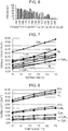
- relations between the thermal conductivity and temperature are illustrated in Fig. 7
- relations between the thermal diffusivity and temperature are illustrated in Fig. 8 , with respect to some main components of the natural gas.
- the calorific value of the mixed gas is calculated without obtaining the ratio of each of the gas components of the gas that is the object of the calorific value measurement.
- a value of heat loss coefficient or thermal conductivity of a plurality of mixed gases is measured at a plurality of temperatures.
- a calorific value calculation formula is generated, on the basis of known calorific values of the plurality of mixed gases and the value of the heat loss coefficient or thermal conductivity measured at the plurality of temperatures, utilizing the heat loss coefficient or thermal conductivity at the plurality of temperatures as the explanatory variables, and the calorific value as the object variable.
- the mentioned calorific value calculation formula is utilized to measure the calorific value of a mixed gas to be measured, the calorific value of which is unknown.
- the value of the heat loss coefficient or thermal conductivity of the mixed gas to be measured, the calorific value of which is unknown is measured at a plurality of temperatures.
- the value of the heat loss coefficient or thermal conductivity of the mixed gas to be measured, measured at the plurality of temperatures are substituted in the explanatory variables, which are the heat loss coefficient or thermal conductivity at the plurality of temperatures, in the calorific value calculation formula, to calculate the calorific value of the mixed gas to be measured.
- NPL 1 " Handbook of Calorimetry and Thermal Analysis” edited by The Japan Society of Calorimetry and Thermal Analysis and published by Maruzen-Yushodo Co., Ltd., 2010, Page 104 .
- the accuracy of the calorific value of the fuel gas obtained from the measurement result of thermal conductivity may be degraded when the composition ratio of the fuel gas fluctuates.
- the present invention has been accomplished to minimize the mentioned drawback, and provides a technique to obtain the fuel gas calorific value with higher accuracy despite large fluctuation of the composition ratio.
- a calorific value measurement apparatus includes a measurement unit that acquires a first value serving as a thermal conductivity index and a second value serving as a thermal diffusivity index, with respect to a fuel gas to be measured, at a first temperature, a second temperature, and a third temperature that are different from each other, a change rate calculation unit that calculates a temperature change rate ⁇ 1 of the first value between the first temperature and the second temperature, measured by the measurement unit, a temperature change rate ⁇ 2 of the first value between the second temperature and the third temperature, a temperature change rate ⁇ 1 of the second value between the first temperature and the second temperature, and a temperature change rate ⁇ 2 of the second value between the second temperature and the third temperature, and a calorific value calculation unit that calculates the calorific value of the fuel gas through a calorific value calculation formula in which the ⁇ 1 , ⁇ 2 , ⁇ 1 , and ⁇ 2 serve as explanatory variables and the calorific value serves as an object variable.
- the calorific value calculation formula is a regression formula obtained through acquiring the first value and the second value, with respect to each of four or more fuel gases the calorific value of which is known, at the first temperature, the second temperature, and the third temperature that are different from each other, acquiring the temperature change rate ⁇ 1 of the first value between the first temperature and the second temperature, the temperature change rate ⁇ 2 of the first value between the second temperature and the third temperature, the temperature change rate ⁇ 1 of the second value between the first temperature and the second temperature, and the temperature change rate ⁇ 2 of the second value between the second temperature and the third temperature, with respect to the first value and the second value of each of the fuel gases, and utilizing relations between the ⁇ 1 , ⁇ 2 , ⁇ 1 , and ⁇ 2 of each of the fuel gases serving as the explanatory variables, and the calorific value of each of the known fuel gases serving as the object variable.
- the measurement unit may include a heat transmitter and a heat receiver, and the first value and the second value may be acquired on a basis of an electrical signal from the heat transmitter and an electrical signal from the heat receiver.
- the calorific value calculation formula may be a regression formula obtained through preparing, as sample gases, four or more fuel gases the calorific value of which is known, the fuel gases being different in composition ratio of component gases from each other, acquiring values of respective electrical signals from the heat transmitter and the heat receiver, the values depending on a temperature of each of the sample gases prepared, heating the heat transmitter contacted by the sample gas at a plurality of heating temperatures, acquiring values of respective electrical signals from the heat transmitter and the heat receiver at each of the heating temperatures, acquiring the temperature change rates ⁇ 1 , ⁇ 2 , ⁇ 1 , and ⁇ 2 of the first value and the second value, acquired on a basis of the values of the electrical signals from the heat transmitter and the heat receiver, and utilizing the ⁇ 1 , ⁇ 2 , ⁇ 1 , and ⁇ 2 as the explanatory variables, and the calorific value of the sample gas as the object variable.
- a calorific value measurement method includes a first step including acquiring a first value serving as a thermal conductivity index and a second value serving as a thermal diffusivity index, with respect to a fuel gas to be measured, at a first temperature, a second temperature, and a third temperature that are different from each other, a second step including calculating a temperature change rate ⁇ 1 of the first value between the first temperature and the second temperature, a temperature change rate ⁇ 2 of the first value between the second temperature and the third temperature, a temperature change rate ⁇ 1 of the second value between the first temperature and the second temperature, and a temperature change rate ⁇ 2 of the second value between the second temperature and the third temperature, and a third step including calculating the calorific value of the fuel gas through a calorific value calculation formula in which the ⁇ 1 , ⁇ 2 , ⁇ 1 , and ⁇ 2 serve as explanatory variables and the calorific value serves as an object variable.
- the calorific value calculation formula is a regression formula obtained through acquiring the first value and the second value, with respect to each of four or more fuel gases the calorific value of which is known, at the first temperature, the second temperature, and the third temperature that are different from each other, acquiring the temperature change rate ⁇ 1 of the first value between the first temperature and the second temperature, the temperature change rate ⁇ 2 of the first value between the second temperature and the third temperature, the temperature change rate ⁇ 1 of the second value between the first temperature and the second temperature, and the temperature change rate ⁇ 2 of the second value between the second temperature and the third temperature, with respect to the first value and the second value of each of the fuel gases, and utilizing relations between the ⁇ 1 , ⁇ 2 , ⁇ 1 , and ⁇ 2 of each of the fuel gases serving as the explanatory variables, and the calorific value of each of the known fuel gases serving as the object variable.
- the first value and the second value may be acquired through measurement of the fuel gas using a measurement unit including a heat transmitter and a heat receiver, on a basis of an electrical signal from the heat transmitter and an electrical signal from the heat receiver.
- the calorific value calculation formula may be obtained through preparing, as sample gases, four or more fuel gases the calorific value of which is known, the fuel gases being different in composition ratio of component gases from each other, acquiring values of respective electrical signals from the heat transmitter and the heat receiver, the values depending on a temperature of each of the sample gases prepared, heating the heat transmitter contacted by the sample gas at a plurality of heating temperatures, acquiring values of respective electrical signals from the heat transmitter and the heat receiver at each of the heating temperatures, acquiring the temperature change rates ⁇ 1 , ⁇ 2 , ⁇ 1 , and ⁇ 2 of the first value and the second value, acquired on a basis of the values of the electrical signals from the heat transmitter and the heat receiver, and utilizing the ⁇ 1 , ⁇ 2 , ⁇ 1 , and ⁇ 2 as the explanatory variables, and the calorific value of the sample gas as the object variable.
- the mentioned arrangement according to the present invention provides an excellent effect of enabling the fuel gas calorific value to be more accurately acquired, despite large fluctuation of the composition ratio.
- the calorific value can be acquired with high accuracy, by employing a change rate of the physical quantity of a fuel gas, obtained when the temperature changes.
- the present inventors have found out that the change rate of the first value and the second value, originating from the temperature change, is insusceptible to measurement accuracy, and useful for improvement in accuracy of the calorific value estimation.
- the calorific value calculation formula is generated, using the measured values as explanatory variables, and the calorific value as the object variable.
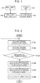
- Fig. 1 is a block diagram illustrating a configuration of a calorific value measurement apparatus according to the embodiment of the present invention.
- the apparatus includes a measurement unit 101, a change rate calculation unit 102, a calorific value calculation unit 103, and a storage unit 104.
- the calorific value measurement apparatus according to this embodiment is a computer device including a central processing unit (CPU), a main storage device, an external storage device, and a network interface, and the above-cited functional units are realized when the CPU operates according to a program installed in the main storage device.
- the functional units may be dispersed in a plurality of computer devices.
- the measurement unit 101 measures a first value and a second value of a fuel gas to be measured, at a first temperature, a second temperature, and a third temperature that are different from each other.
- the first value serves as an index of the thermal conductivity of the fuel gas to be measured, which is derived, for example, utilizing a predetermined correlation based on the heat loss coefficient of the fuel gas to be measured.
- the second value serves as an index of the thermal diffusivity of the fuel gas to be measured, which is derived, for example, utilizing a predetermined correlation based on a transitional response of a temperature rise, measured when the fuel gas to be measured is heated.
- the specific configuration of the measurement unit 101 will be subsequently described.
- the change rate calculation unit 102 calculates a temperature change rate ⁇ 1 of the first value between the first temperature and the second temperature, and a temperature change rate ⁇ 2 of the first value between the second temperature and the third temperature, on the basis of the first value measured by the measurement unit 101. In addition, the change rate calculation unit 102 calculates a temperature change rate ⁇ 1 of the second value between the first temperature and the second temperature, and a temperature change rate ⁇ 2 of the second value between the second temperature and the third temperature, on the basis of the first value measured by the measurement unit 101.
- the calorific value calculation unit 103 calculates the calorific value of the fuel gas through a calorific value calculation formula in which the ⁇ 1 , ⁇ 2 , ⁇ 1 , and ⁇ 2 serve as explanatory variables and the calorific value serves as an object variable.
- the calorific value calculation formula is stored in the storage unit 104.
- the calorific value calculation formula can be expressed as a regression formula obtained as follows. First, the first value and the second value are measured with respect to each of four or more fuel gases, the calorific value of which is known, at the first temperature, the second temperature, and the third temperature that are different from each other. Then the temperature change rate ⁇ 1 of the first value between the first temperature and the second temperature, and the temperature change rate ⁇ 2 of the first value between the second temperature and the third temperature are acquired, with respect to each of the fuel gases. In addition, the temperature change rate ⁇ 1 of the second value between the first temperature and the second temperature, and the temperature change rate ⁇ 2 of the second value between the second temperature and the third temperature are acquired.
- the regression formula cited hereunder is derived, utilizing the temperature change rates ⁇ 1 , ⁇ 2 , ⁇ 1 , and ⁇ 2 of each of the fuel gases as the explanatory variables, and the calorific value of each of the known fuel gases as the object variable.
- a coefficient c i and degrees n1, n2, n3, and n4 in the following regression formula are analytically obtained, on the basis of the known calorific value of each of the fuel gases, and the ⁇ 1 , ⁇ 2 , ⁇ 1 , and ⁇ 2 .
- c i represents a coefficient.
- f ⁇ 1 ⁇ 2 ⁇ 1 ⁇ 2 ⁇ c i ⁇ 1 n 1 ⁇ 2 n 2 ⁇ 1 n 3 ⁇ 2 n 4
- the calorific value of the fuel gas can be calculated, through the calorific value calculation formula derived as above.
- the measurement unit 101 acquires a first value k 1 at a first temperature T 1 . Then the measurement unit 101 acquires a second value a 1 , at the first temperature T 1 , at step S102. Likewise, at each of a second temperature T 2 and a third temperature T 3 , the acquisition of the first value and the second value by the measurement unit 101 is performed at the first temperature T 1 , the second temperature T 2 , and the third temperature T 3 , which are different from each other (step S101 to step S103), so that the first value k 1 , a first value k 2 , a first value k 3 , the second value a 1 , a second value a 2 , and a second value a 3 are acquired.
- the change rate calculation unit 102 acquires the temperature change rate ⁇ 1 of the first value between the first temperature T 1 and the second temperature T 2 , and the temperature change rate ⁇ 2 of the first value between the second temperature T 2 and the third temperature T 3 , as indicated hereunder.
- ⁇ 1 k 2 ⁇ k 1 T 2 ⁇ T 1
- ⁇ 2 k 3 ⁇ k 2 T 3 ⁇ T 2
- the change rate calculation unit 102 acquires the temperature change rate ⁇ 1 of the second value between the first temperature T 1 and the second temperature T 2 , and the temperature change rate ⁇ 2 of the second value between the second temperature T 2 and the third temperature T 3 , as indicated hereunder.
- ⁇ 1 a 2 ⁇ a 1 T 2 ⁇ T 1
- ⁇ 2 a 3 ⁇ a 2 T 3 ⁇ T 2
- the calorific value calculation unit 103 calculates the calorific value of the fuel gas, through the calorific value calculation formula in which the ⁇ 1 , ⁇ 2 , ⁇ 1 , and ⁇ 2 serve as the explanatory variables, and the calorific value serves as the object variable.
- the calorific value calculation formula is, as described above, the regression formula obtained from the known calorific value, the temperature change rate ⁇ 1 of the first value between the first temperature T 1 and the second temperature T 2 , the temperature change rate ⁇ 2 of the first value between the second temperature T 2 and the third temperature T 3 , the temperature change rate ⁇ 1 of the second value between the first temperature T 1 and the second temperature T 2 , and the temperature change rate ⁇ 2 of the second value between the second temperature T 2 and the third temperature T 3 , of each of four or more fuel gases the calorific value of which is known, on the basis of the first value and the second value measured at the first temperature T 1 , the second temperature T 2 , and the third temperature T 3 that are different from each other, with respect to each of the fuel gases.
- the gas calorific value can be acquired with higher accuracy, despite large fluctuation of the gas composition of the object to be measured.
- the measurement unit including a heat transmitter and a heat receiver is employed, to acquire the first value and the second value on the basis of an electrical signal from the heat transmitter and an electrical signal from the heat receiver, as described below.
- a heat transmitter 201 and a heat receiver 202 are employed to measure an ambient gas 211, for example as illustrated in Fig. 3 .
- the heat transmitter 201 and the heat receiver 202 are resistance temperature detector elements, for example constituted of platinum.
- the gas 211 is stored, for example, in a measurement chamber of a predetermined processing apparatus, with stabilized gas flow and gas pressure.
- a heat loss coefficient can be obtained on the basis of power consumption to drive the heat transmitter 201 to attain the temperature T 1 , and a difference in temperature between the heat transmitter 201 and the heat receiver 202. It is known that the heat loss coefficient is correlated with the first value of the gas at the temperature T 1 . Therefore, a value obtained on the basis of the mentioned correlation, from the heat loss coefficient acquired when the heat transmitter 201 is driven to the temperature T1, is taken as the first value k 1 at the temperature T 1 .
- a current is applied, for example at the time point t 1 so as to raise the temperature of the heat transmitter 201 by ⁇ T (electrical resistance that realizes temperature T 1 + ⁇ T corresponds to the r drive ).
- the temperature change rate will be described.
- the first value k 2 and the second value a 2 at the temperature T 2 and the first value k 3 and the second value a 3 at the temperature T 3 are acquired, in the same manner as acquiring the first value k 1 and the second value a 1 at the temperature T 1 .
- the ⁇ 1 , ⁇ 2 , ⁇ 1 , and ⁇ 2 are acquired, according to the equations (1) and (2) cited earlier.
- the calorific value of which is known, are utilized to acquire the ⁇ 1 , ⁇ 2 , ⁇ 1 , and ⁇ 2 of each of the gases.
- a plurality of sample gases each containing, for example, oxygen gas, nitrogen gas, carbon dioxide gas, methane gas, ethane gas, propane gas, and butane gas, but in different composition ratios, are prepared.
- the ⁇ 1 , ⁇ 2 , ⁇ 1 , ⁇ 2 are acquired, with respect to each of the plurality of sample gases prepared.
- the calorific value of each of the plurality of sample gases is known.
- composition ratio (Table 1)
- measurement results with respect to the corresponding composition (Table 2) are indicated hereunder.
- the numerals in the tables represent a percentage in volume.
- a regression formula is generated with respect to each of the gases by multi-variable analysis, on the basis of a plurality of relations in which the ⁇ 1 , ⁇ 2 , ⁇ 1 , ⁇ 2 serve as the explanatory variables, and the known calorific value of each of the fuel gases serves as the object variable.
- the multi-variable analysis applicable to the generation of the regression formula may be, for example, a support vector regression.
- the regression formula generated as above may be stored in the storage unit 104, as the calorific value calculation formula.
- the arrangement according to the embodiment enables the calorific value to be acquired with higher accuracy, for example compared with the technique according to PTL 1.
- the acquisition of the calorific value will be studied, with respect to 2172 types of mixed gases (fuel gases) each containing, for example, methane gas in a variation range of 68 to 100%, ethane gas in a variation range of 0 to 24%, propane gas in a variation range of 0 to 6%, butane gas in a variation range of 0 to 3%, oxygen gas in a variation range of 0 to 0.2%, nitrogen gas in a variation range of 0 to 15%, and carbon dioxide gas in a variation range of 0 to 9%.
- fuel gases fuel gases
- 343 types of mixed gases were selected as the sample gases out of the 2172 types of mixed gases, the composition ratio of which largely varies, and a regression formula was generated with respect to each of the sample gases by multi-variable analysis, on the basis of a plurality of relations in which the ⁇ 1 , ⁇ 2 , ⁇ 1 , ⁇ 2 serve as the explanatory variables, and the calorific value of each of the sample gases serves as the object variable.
- the first values k 1 , k 2 , k 3 , k 4 , and k 5 were acquired with respect to each of the fuel gases, at five temperatures different from each other, as described in PTL 1, and a regression formula was generated by multi-variable analysis, on the basis of a plurality of relations in which the first value k 1 , k 2 , k 3 , k 4 , and k 5 acquired as above serve as the explanatory variables, and the calorific value of each of the sample gases serves as the object variable.
- the calorific value is acquired through the calorific value calculation formula, in which the temperature change rate of the first value and the temperature change rate of the second value serve as the explanatory variables, and the calorific value of the fuel gas serves as the object variable. Therefore, the gas calorific value can be acquired with higher accuracy, despite large fluctuation of the composition ratio.
Landscapes
- Chemical & Material Sciences (AREA)
- Health & Medical Sciences (AREA)
- Life Sciences & Earth Sciences (AREA)
- Immunology (AREA)
- Analytical Chemistry (AREA)
- Biochemistry (AREA)
- General Health & Medical Sciences (AREA)
- General Physics & Mathematics (AREA)
- Physics & Mathematics (AREA)
- Pathology (AREA)
- Engineering & Computer Science (AREA)
- Chemical Kinetics & Catalysis (AREA)
- General Chemical & Material Sciences (AREA)
- Oil, Petroleum & Natural Gas (AREA)
- Food Science & Technology (AREA)
- Medicinal Chemistry (AREA)
- Investigating Or Analyzing Materials Using Thermal Means (AREA)
Abstract
Description
- The present invention relates to an apparatus and a method for measuring a calorific value, and more particularly to an apparatus and a method for measuring a calorific value of city gas or other type of gas, predominantly composed of natural gas.
- For example, the city gas is prepared by mixing petroleum gas (PG) in the natural gas (NG), which is the main material, and supplied after the calorific value is adjusted to a predetermined level. A most basic method for measuring the calorific value of such fuel gas is burning the gas, and measuring the calorific value. To measure the calorific value of the fuel gas, the relation between gas density and the calorific value may also be utilized. In addition, a method of calculating the calorific value on the basis of the thermal conductivity of the fuel gas has also been proposed (see PTL 1).
- Since the calorific value of a single-component gas can be uniquely identified, the calorific value of a mixed gas can be calculated on the basis of the gas composition when the gas type (components) and the ratio thereof are known. Here, relations between the thermal conductivity and temperature are illustrated in
Fig. 7 , and relations between the thermal diffusivity and temperature are illustrated inFig. 8 , with respect to some main components of the natural gas. - With the technique according to PTL 1, the calorific value of the mixed gas is calculated without obtaining the ratio of each of the gas components of the gas that is the object of the calorific value measurement. With the mentioned technique, first, a value of heat loss coefficient or thermal conductivity of a plurality of mixed gases is measured at a plurality of temperatures. Then a calorific value calculation formula is generated, on the basis of known calorific values of the plurality of mixed gases and the value of the heat loss coefficient or thermal conductivity measured at the plurality of temperatures, utilizing the heat loss coefficient or thermal conductivity at the plurality of temperatures as the explanatory variables, and the calorific value as the object variable.
- With the technique according to PTL 1, the mentioned calorific value calculation formula is utilized to measure the calorific value of a mixed gas to be measured, the calorific value of which is unknown. First, the value of the heat loss coefficient or thermal conductivity of the mixed gas to be measured, the calorific value of which is unknown, is measured at a plurality of temperatures. Then the value of the heat loss coefficient or thermal conductivity of the mixed gas to be measured, measured at the plurality of temperatures, are substituted in the explanatory variables, which are the heat loss coefficient or thermal conductivity at the plurality of temperatures, in the calorific value calculation formula, to calculate the calorific value of the mixed gas to be measured.
- PTL 1: Japanese Patent No.
5075986 - NPL 1: "Handbook of Calorimetry and Thermal Analysis" edited by The Japan Society of Calorimetry and Thermal Analysis and published by Maruzen-Yushodo Co., Ltd., 2010, .
- With the mentioned technique of calculating the calorific value on the basis of the thermal conductivity, however, the accuracy of the calorific value of the fuel gas obtained from the measurement result of thermal conductivity may be degraded when the composition ratio of the fuel gas fluctuates.
- The present invention has been accomplished to minimize the mentioned drawback, and provides a technique to obtain the fuel gas calorific value with higher accuracy despite large fluctuation of the composition ratio.
- A calorific value measurement apparatus according to the present invention includes a measurement unit that acquires a first value serving as a thermal conductivity index and a second value serving as a thermal diffusivity index, with respect to a fuel gas to be measured, at a first temperature, a second temperature, and a third temperature that are different from each other, a change rate calculation unit that calculates a temperature change rate κ1 of the first value between the first temperature and the second temperature, measured by the measurement unit, a temperature change rate κ2 of the first value between the second temperature and the third temperature, a temperature change rate α1 of the second value between the first temperature and the second temperature, and a temperature change rate α2 of the second value between the second temperature and the third temperature, and a calorific value calculation unit that calculates the calorific value of the fuel gas through a calorific value calculation formula in which the κ1, κ2, α1, and α2 serve as explanatory variables and the calorific value serves as an object variable. The calorific value calculation formula is a regression formula obtained through acquiring the first value and the second value, with respect to each of four or more fuel gases the calorific value of which is known, at the first temperature, the second temperature, and the third temperature that are different from each other, acquiring the temperature change rate κ1 of the first value between the first temperature and the second temperature, the temperature change rate κ2 of the first value between the second temperature and the third temperature, the temperature change rate α1 of the second value between the first temperature and the second temperature, and the temperature change rate α2 of the second value between the second temperature and the third temperature, with respect to the first value and the second value of each of the fuel gases, and utilizing relations between the κ1, κ2, α1, and α2 of each of the fuel gases serving as the explanatory variables, and the calorific value of each of the known fuel gases serving as the object variable.
- In the calorific value measurement apparatus, the measurement unit may include a heat transmitter and a heat receiver, and the first value and the second value may be acquired on a basis of an electrical signal from the heat transmitter and an electrical signal from the heat receiver.
- In the calorific value measurement apparatus, the calorific value calculation formula may be a regression formula obtained through preparing, as sample gases, four or more fuel gases the calorific value of which is known, the fuel gases being different in composition ratio of component gases from each other, acquiring values of respective electrical signals from the heat transmitter and the heat receiver, the values depending on a temperature of each of the sample gases prepared, heating the heat transmitter contacted by the sample gas at a plurality of heating temperatures, acquiring values of respective electrical signals from the heat transmitter and the heat receiver at each of the heating temperatures, acquiring the temperature change rates κ1, κ2, α1, and α2 of the first value and the second value, acquired on a basis of the values of the electrical signals from the heat transmitter and the heat receiver, and utilizing the κ1, κ2, α1, and α2 as the explanatory variables, and the calorific value of the sample gas as the object variable.
- A calorific value measurement method according to the present invention includes a first step including acquiring a first value serving as a thermal conductivity index and a second value serving as a thermal diffusivity index, with respect to a fuel gas to be measured, at a first temperature, a second temperature, and a third temperature that are different from each other, a second step including calculating a temperature change rate κ1 of the first value between the first temperature and the second temperature, a temperature change rate κ2 of the first value between the second temperature and the third temperature, a temperature change rate α1 of the second value between the first temperature and the second temperature, and a temperature change rate α2 of the second value between the second temperature and the third temperature, and a third step including calculating the calorific value of the fuel gas through a calorific value calculation formula in which the κ1, κ2, α1, and α2 serve as explanatory variables and the calorific value serves as an object variable. The calorific value calculation formula is a regression formula obtained through acquiring the first value and the second value, with respect to each of four or more fuel gases the calorific value of which is known, at the first temperature, the second temperature, and the third temperature that are different from each other, acquiring the temperature change rate κ1 of the first value between the first temperature and the second temperature, the temperature change rate κ2 of the first value between the second temperature and the third temperature, the temperature change rate α1 of the second value between the first temperature and the second temperature, and the temperature change rate α2 of the second value between the second temperature and the third temperature, with respect to the first value and the second value of each of the fuel gases, and utilizing relations between the κ1, κ2, α1, and α2 of each of the fuel gases serving as the explanatory variables, and the calorific value of each of the known fuel gases serving as the object variable.
- In the calorific value measurement method, the first value and the second value may be acquired through measurement of the fuel gas using a measurement unit including a heat transmitter and a heat receiver, on a basis of an electrical signal from the heat transmitter and an electrical signal from the heat receiver.
- In the calorific value measurement method, the calorific value calculation formula may be obtained through preparing, as sample gases, four or more fuel gases the calorific value of which is known, the fuel gases being different in composition ratio of component gases from each other, acquiring values of respective electrical signals from the heat transmitter and the heat receiver, the values depending on a temperature of each of the sample gases prepared, heating the heat transmitter contacted by the sample gas at a plurality of heating temperatures, acquiring values of respective electrical signals from the heat transmitter and the heat receiver at each of the heating temperatures, acquiring the temperature change rates κ1, κ2, α1, and α2 of the first value and the second value, acquired on a basis of the values of the electrical signals from the heat transmitter and the heat receiver, and utilizing the κ1, κ2, α1, and α2 as the explanatory variables, and the calorific value of the sample gas as the object variable. Advantageous Effects of Invention
- The mentioned arrangement according to the present invention provides an excellent effect of enabling the fuel gas calorific value to be more accurately acquired, despite large fluctuation of the composition ratio.
-
- [
Fig. 1] Fig. 1 is a block diagram illustrating a configuration of a calorific value measurement apparatus according to an embodiment of the present invention. - [
Fig. 2] Fig. 2 is a flowchart for explaining a calorific value measurement method according to the embodiment of the present invention. - [
Fig. 3] Fig. 3 is a schematic drawing for explaining the concept of measurement of a first value and a second value. - [
Fig. 4] Fig. 4 is a characteristic graph illustrating a change in resistance of a heat transmitter and a heat receiver. - [
Fig. 5] Fig. 5 is a characteristic graph illustrating deviations in calculation result of calorific value obtained by a regression formula according to the embodiment, with respect to 2172 types of mixed gases. - [
Fig. 6] Fig. 6 is a characteristic graph illustrating deviations in calculation result of calorific value obtained by a regression formula according to a comparative example, with respect to 2172 types of mixed gases. - [
Fig. 7] Fig. 7 is a characteristic graph illustrating a relation between temperature and thermal conductivity, with respect to main components of natural gas. - [
Fig. 8] Fig. 8 is a characteristic graph illustrating a relation between temperature and thermal diffusivity, with respect to main components of natural gas. - As result of diligent studies carried out by the present inventors under the circumstance where further improvement in measurement accuracy is sought for, it has proved that the calorific value can be acquired with high accuracy, by employing a change rate of the physical quantity of a fuel gas, obtained when the temperature changes. The present inventors have found out that the change rate of the first value and the second value, originating from the temperature change, is insusceptible to measurement accuracy, and useful for improvement in accuracy of the calorific value estimation. In the present invention, further, the calorific value calculation formula is generated, using the measured values as explanatory variables, and the calorific value as the object variable. Accordingly, it is not mandatory in the present invention that a true thermal conductivity and a true thermal diffusivity are measured, but it suffices that an index (value), reflecting the true thermal conductivity and the true thermal diffusivity with high reproducibility, is acquired. Thus, the alleviation of restriction to the
- measurement is another important feature of the present invention.
- Hereafter, an embodiment of the present invention will be described, with reference to the drawings.
Fig. 1 is a block diagram illustrating a configuration of a calorific value measurement apparatus according to the embodiment of the present invention. The apparatus includes ameasurement unit 101, a changerate calculation unit 102, a calorificvalue calculation unit 103, and astorage unit 104. The calorific value measurement apparatus according to this embodiment is a computer device including a central processing unit (CPU), a main storage device, an external storage device, and a network interface, and the above-cited functional units are realized when the CPU operates according to a program installed in the main storage device. Alternatively, the functional units may be dispersed in a plurality of computer devices. - The
measurement unit 101 measures a first value and a second value of a fuel gas to be measured, at a first temperature, a second temperature, and a third temperature that are different from each other. The first value serves as an index of the thermal conductivity of the fuel gas to be measured, which is derived, for example, utilizing a predetermined correlation based on the heat loss coefficient of the fuel gas to be measured. The second value serves as an index of the thermal diffusivity of the fuel gas to be measured, which is derived, for example, utilizing a predetermined correlation based on a transitional response of a temperature rise, measured when the fuel gas to be measured is heated. The specific configuration of themeasurement unit 101 will be subsequently described. - The change
rate calculation unit 102 calculates a temperature change rate κ1 of the first value between the first temperature and the second temperature, and a temperature change rate κ2 of the first value between the second temperature and the third temperature, on the basis of the first value measured by themeasurement unit 101. In addition, the changerate calculation unit 102 calculates a temperature change rate α1 of the second value between the first temperature and the second temperature, and a temperature change rate α2 of the second value between the second temperature and the third temperature, on the basis of the first value measured by themeasurement unit 101. - The calorific
value calculation unit 103 calculates the calorific value of the fuel gas through a calorific value calculation formula in which the κ1, κ2, α1, and α2 serve as explanatory variables and the calorific value serves as an object variable. The calorific value calculation formula is stored in thestorage unit 104. - Now, the calorific value calculation formula can be expressed as a regression formula obtained as follows. First, the first value and the second value are measured with respect to each of four or more fuel gases, the calorific value of which is known, at the first temperature, the second temperature, and the third temperature that are different from each other. Then the temperature change rate κ1 of the first value between the first temperature and the second temperature, and the temperature change rate κ2 of the first value between the second temperature and the third temperature are acquired, with respect to each of the fuel gases. In addition, the temperature change rate α1 of the second value between the first temperature and the second temperature, and the temperature change rate α2 of the second value between the second temperature and the third temperature are acquired. Then, the regression formula cited hereunder is derived, utilizing the temperature change rates κ1, κ2, α1, and α2 of each of the fuel gases as the explanatory variables, and the calorific value of each of the known fuel gases as the object variable. In other words, a coefficient ci and degrees n1, n2, n3, and n4 in the following regression formula are analytically obtained, on the basis of the known calorific value of each of the fuel gases, and the κ1, κ2, α1, and α2. In the following formula, ci represents a coefficient. The degrees may be set, for example, as n1 + n2 + n3 + n4 = 0 to 3.

- The calorific value of the fuel gas can be calculated, through the calorific value calculation formula derived as above.
- Hereunder, an example of the operation of the calorific value measurement apparatus (calorific value measurement method) according to the embodiment of the present invention will be described, with reference to the flowchart illustrated in
Fig. 2 . - First, at step S101, the
measurement unit 101 acquires a first value k1 at a first temperature T1. Then themeasurement unit 101 acquires a second value a1, at the first temperature T1, at step S102. Likewise, at each of a second temperature T2 and a third temperature T3, the acquisition of the first value and the second value by themeasurement unit 101 is performed at the first temperature T1, the second temperature T2, and the third temperature T3, which are different from each other (step S101 to step S103), so that the first value k1, a first value k2, a first value k3, the second value a1, a second value a2, and a second value a3 are acquired. - Then at step S104, the change
rate calculation unit 102 acquires the temperature change rate κ1 of the first value between the first temperature T1 and the second temperature T2, and the temperature change rate κ2 of the first value between the second temperature T2 and the third temperature T3, as indicated hereunder.
[Math. 2]
- At step S105, the change
rate calculation unit 102 acquires the temperature change rate α1 of the second value between the first temperature T1 and the second temperature T2, and the temperature change rate α2 of the second value between the second temperature T2 and the third temperature T3, as indicated hereunder.
[Math. 3]
- Thereafter, at step S106, the calorific
value calculation unit 103 calculates the calorific value of the fuel gas, through the calorific value calculation formula in which the κ1, κ2, α1, and α2 serve as the explanatory variables, and the calorific value serves as the object variable. - Here, the calorific value calculation formula is, as described above, the regression formula obtained from the known calorific value, the temperature change rate κ1 of the first value between the first temperature T1 and the second temperature T2, the temperature change rate κ2 of the first value between the second temperature T2 and the third temperature T3, the temperature change rate α1 of the second value between the first temperature T1 and the second temperature T2, and the temperature change rate α2 of the second value between the second temperature T2 and the third temperature T3, of each of four or more fuel gases the calorific value of which is known, on the basis of the first value and the second value measured at the first temperature T1, the second temperature T2, and the third temperature T3 that are different from each other, with respect to each of the fuel gases.
- With the arrangement according to the embodiment, the gas calorific value can be acquired with higher accuracy, despite large fluctuation of the gas composition of the object to be measured.
- The measurement of the first value and the second value will now be described hereunder. To measure these values, the measurement unit including a heat transmitter and a heat receiver is employed, to acquire the first value and the second value on the basis of an electrical signal from the heat transmitter and an electrical signal from the heat receiver, as described below.
- First, the measurement of the first value will be described. To measure the first value, a
heat transmitter 201 and aheat receiver 202 are employed to measure anambient gas 211, for example as illustrated inFig. 3 . Theheat transmitter 201 and theheat receiver 202 are resistance temperature detector elements, for example constituted of platinum. Thegas 211 is stored, for example, in a measurement chamber of a predetermined processing apparatus, with stabilized gas flow and gas pressure. - It will be assumed that the
heat transmitter 201, theheat receiver 202, and theambient gas 211 are in a steady state at a temperature T0. In this state, the respective electrical resistances of theheat transmitter 201 and theheat receiver 202 accord with each other, at rbase = r0 corresponding to the temperature T0. - When a current is applied in this state to the
heat transmitter 201, for example at a time point t1, so as to make the electrical resistance of the heat transmitter 201 rdrive = r1 corresponding to a temperature T1, the temperature (electrical resistance) of theheat receiver 202 assumes a steady state at a time point t2, as illustrated inFig. 4 . InFig. 4 , solid lines represent the change in electrical resistance of theheat transmitter 201, and dot lines represent the change in electrical resistance of theheat receiver 202. In this state, a temperature slope is formed in thegas 211 between theheat transmitter 201 and theheat receiver 202. - As described in PTL 1, a heat loss coefficient can be obtained on the basis of power consumption to drive the
heat transmitter 201 to attain the temperature T1, and a difference in temperature between theheat transmitter 201 and theheat receiver 202. It is known that the heat loss coefficient is correlated with the first value of the gas at the temperature T1. Therefore, a value obtained on the basis of the mentioned correlation, from the heat loss coefficient acquired when theheat transmitter 201 is driven to the temperature T1, is taken as the first value k1 at the temperature T1. - The measurement of the second value will be described hereunder. When the
heat transmitter 201, theheat receiver 202, and thegas 211 are in the steady state at the temperature T1, the respective electrical resistances of theheat transmitter 201 and theheat receiver 202 accord with each other, at rbase = r1 corresponding to the temperature T1. - In this state a current is applied, for example at the time point t1 so as to raise the temperature of the
heat transmitter 201 by ΔT (electrical resistance that realizes temperature T1 + ΔT corresponds to the rdrive). - It is widely known, through observation of the temperature of the
gas 211 with theheat receiver 202 upon heating thegas 211 with theheat transmitter 201, that a transitional response of the temperature rise observed at theheat receiver 202 and the second value of thegas 211 are correlated with each other (see NPL 1). Examples of parameters for evaluating the transitional response include the following. -
- Time constant of the transitional response of the temperature rise of the
heat receiver 202; - Time until the temperature of the
heat receiver 202 rises by a certain amount after theheat transmitter 201 starts the heating; and - Temperature of
heat receiver 202 measured when a certain period of time has elapsed after theheat transmitter 201 started the heating. - Accordingly, a value obtained on the basis of the correlation, from the parameter (indices cited above, such as the time constant) for measuring the transitional response of the temperature (electrical resistance) of the
heat receiver 202, when the temperature of theheat transmitter 201 is raised by ΔT, after theheat transmitter 201, theheat receiver 202, and thegas 211 entered the steady state at the temperature T1, is taken as the second value a1 at the temperature T1. - Hereunder, the temperature change rate will be described. As stated above, the first value k2 and the second value a2 at the temperature T2, and the first value k3 and the second value a3 at the temperature T3 are acquired, in the same manner as acquiring the first value k1 and the second value a1 at the temperature T1. On the basis of the values acquired as above, the κ1, κ2, α1, and α2 are acquired, according to the equations (1) and (2) cited earlier.
- The generation of the calorific value calculation formula will now be described hereunder. To generate the calorific value calculation formula, for example, four or more gases, the calorific value of which is known, are utilized to acquire the κ1, κ2, α1, and α2 of each of the gases. A plurality of sample gases each containing, for example, oxygen gas, nitrogen gas, carbon dioxide gas, methane gas, ethane gas, propane gas, and butane gas, but in different composition ratios, are prepared. Then the κ1, κ2, α1, α2 are acquired, with respect to each of the plurality of sample gases prepared. The calorific value of each of the plurality of sample gases is known.
- Regarding the sample gases prepared as above, the composition ratio (Table 1), and the measurement results with respect to the corresponding composition (Table 2) are indicated hereunder. The numerals in the tables represent a percentage in volume.
-
Table 1 Sample Composition Sample Oxygen Nitrogen Carbon Dioxide Methane Ethane Propane Butane 1 0 3 9 88.00 0 0 0 2 0.2 6 6 82.80 3 2 0 3 0.2 6 3 85.80 3 2 0 4 0 3 3 76.00 18 0 0 5 0 12 6 72.00 6 4 0 6 0.2 15 9 69.80 3 2 1 7 0 3 6 71.00 15 4 1 8 0.2 3 3 72.80 18 2 1 9 0.2 9 3 76.80 9 2 0 10 0.2 12 0 73.80 6 6 2 -
Table 2 Measurement Result Sample 75°C 125°C 175°C Temperature Change Rate Calorific Value κ1 α1 κ2 α2 κ3 α3 κ1 κ2 α1 α2 1 38.78 29.01 46.37 37.57 54.59 47.07 0.152 0.164 0.171 0.190 35.13 2 38.07 27.57 45.58 35.66 53.72 44.64 0.150 0.163 0.162 0.180 37.20 3 38.77 28.12 46.42 36.34 54.72 45.47 0.153 0.166 0.164 0.183 38.40 4 37.19 25.32 44.96 32.81 53.41 41.15 0.155 0.169 0.150 0.167 43.02 5 36.41 25.68 43.61 33.19 51.38 41.55 0.144 0.155 0.150 0.167 37.03 6 36.03 26.08 42.97 33.72 50.43 42.21 0.139 0.149 0.153 0.170 33.35 7 35.66 23.14 43.19 29.99 51.37 37.63 0.151 0.164 0.137 0.153 44.31 8 36.32 23.77 44.00 30.80 52.37 38.64 0.154 0.167 0.141 0.157 45.11 9 37.44 26.46 44.93 34.22 53.04 42.84 0.150 0.162 0.155 0.172 39.03 10 36.55 24.34 43.88 31.41 51.84 39.28 0.147 0.159 0.141 0.157 42.46 - A regression formula is generated with respect to each of the gases by multi-variable analysis, on the basis of a plurality of relations in which the κ1, κ2, α1, α2 serve as the explanatory variables, and the known calorific value of each of the fuel gases serves as the object variable. The multi-variable analysis applicable to the generation of the regression formula may be, for example, a support vector regression. The regression formula generated as above may be stored in the
storage unit 104, as the calorific value calculation formula. - Although ten types of gases are utilized, to obtain the regression formula on the basis of the ten relations in which the κ1, κ2, α1, α2 serve as the explanatory variables and the known calorific value of each of the fuel gases serves as the object variable in the foregoing example, a different method may be adopted. Generating the regression formula from a wider range of gases further improves statistical reliability of the calorific value, acquired through the regression formula (calorific value calculation formula) thus generated.
- The arrangement according to the embodiment enables the calorific value to be acquired with higher accuracy, for example compared with the technique according to PTL 1. Here, the acquisition of the calorific value will be studied, with respect to 2172 types of mixed gases (fuel gases) each containing, for example, methane gas in a variation range of 68 to 100%, ethane gas in a variation range of 0 to 24%, propane gas in a variation range of 0 to 6%, butane gas in a variation range of 0 to 3%, oxygen gas in a variation range of 0 to 0.2%, nitrogen gas in a variation range of 0 to 15%, and carbon dioxide gas in a variation range of 0 to 9%.
- According to the embodiment, 343 types of mixed gases were selected as the sample gases out of the 2172 types of mixed gases, the composition ratio of which largely varies, and a regression formula was generated with respect to each of the sample gases by multi-variable analysis, on the basis of a plurality of relations in which the κ1, κ2, α1, α2 serve as the explanatory variables, and the calorific value of each of the sample gases serves as the object variable.
- As a comparative example, the first values k1, k2, k3, k4, and k5 were acquired with respect to each of the fuel gases, at five temperatures different from each other, as described in PTL 1, and a regression formula was generated by multi-variable analysis, on the basis of a plurality of relations in which the first value k1, k2, k3, k4, and k5 acquired as above serve as the explanatory variables, and the calorific value of each of the sample gases serves as the object variable.
- The variation in accuracy (estimated error rate) in the acquisition result of the calorific value with the regression formula according to the embodiment, with respect to each of the 2172 types of mixed gases (fuel gases), has proved to be narrow, as illustrated in
Fig. 5 . In contrast, the variation in accuracy in the acquisition result of the calorific value with the regression formula according to the comparative example, with respect to each of the 2172 types of mixed gases (fuel gases), has proved to be large, as illustrated inFig. 6 . - According to the present invention, as described thus far, the calorific value is acquired through the calorific value calculation formula, in which the temperature change rate of the first value and the temperature change rate of the second value serve as the explanatory variables, and the calorific value of the fuel gas serves as the object variable. Therefore, the gas calorific value can be acquired with higher accuracy, despite large fluctuation of the composition ratio.
- It should be noted that the present invention is in no way limited to the foregoing embodiment. It is obvious that various modifications and combinations may be made by those skilled in the art, within the technical scope of the present invention.
-
- 101
- measurement unit
- 102
- change rate calculation unit
- 103
- calorific value calculation unit
- 104
- storage unit
Claims (6)
- A calorific value measurement method comprising:a first step including acquiring a first value serving as a thermal conductivity index and a second value serving as a thermal diffusivity index, with respect to a fuel gas to be measured, at a first temperature, a second temperature, and a third temperature that are different from each other;a second step including calculating a temperature change rate κ1 of the first value between the first temperature and the second temperature, a temperature change rate κ2 of the first value between the second temperature and the third temperature, a temperature change rate α1 of the second value between the first temperature and the second temperature, and a temperature change rate α2 of the second value between the second temperature and the third temperature; anda third step including calculating a calorific value of the fuel gas through a calorific value calculation formula in which the κ1, κ2, α1, and α2 serve as explanatory variables and the calorific value serves as an object variable,wherein the calorific value calculation formula is a regression formula obtained through acquiring the first value and the second value, with respect to each of four or more fuel gases the calorific value of which is known, at the first temperature, the second temperature, and the third temperature that are different from each other, acquiring the temperature change rate κ1 of the first value between the first temperature and the second temperature, the temperature change rate κ2 of the first value between the second temperature and the third temperature, the temperature change rate α1 of the second value between the first temperature and the second temperature, and the temperature change rate α2 of the second value between the second temperature and the third temperature, with respect to the first value and the second value of each of the fuel gases, and utilizing relations between the κ1, κ2, α1, and α2 of each of the fuel gases serving as the explanatory variables, and the calorific value of each of the known fuel gases serving as the object variable.
- The calorific value measurement method according to Claim 1,
wherein the first value and the second value are acquired through measurement of the fuel gas using a measurement unit including a heat transmitter and a heat receiver, on a basis of an electrical signal from the heat transmitter and an electrical signal from the heat receiver. - The calorific value measurement method according to Claim 2,
wherein the calorific value calculation formula is obtained through:preparing, as sample gases, four or more fuel gases the calorific value of which is known, the fuel gases being different in composition ratio of component gases from each other;acquiring values of respective electrical signals from the heat transmitter and the heat receiver, the values depending on a temperature of each of the sample gases prepared;heating the heat transmitter contacted by the sample gas at a plurality of heating temperatures;acquiring values of respective electrical signals from the heat transmitter and the heat receiver at each of the heating temperatures;acquiring the temperature change rates κ1, κ2, α1, and α2 of the first value and the second value, acquired on a basis of the values of the electrical signals from the heat transmitter and the heat receiver; andutilizing the κ1, κ2, α1, and α2 as the explanatory variables, and the calorific value of the sample gas as the object variable. - A calorific value measurement apparatus comprising:a measurement unit configured to acquire a first value serving as a thermal conductivity index and a second value serving as a thermal diffusivity index, with respect to a fuel gas to be measured, at a first temperature, a second temperature, and a third temperature that are different from each other;a change rate calculation unit configured to calculate a temperature change rate κ1 of the first value between the first temperature and the second temperature, measured by the measurement unit, a temperature change rate κ2 of the first value between the second temperature and the third temperature, a temperature change rate α1 of the second value between the first temperature and the second temperature, and a temperature change rate α2 of the second value between the second temperature and the third temperature; anda calorific value calculation unit configured to calculate a calorific value of the fuel gas through a calorific value calculation formula in which the κ1, κ2, α1, and α2 serve as explanatory variables and the calorific value serves as an object variable,wherein the calorific value calculation formula is a regression formula obtained through acquiring the first value and the second value, with respect to each of four or more fuel gases the calorific value of which is known, at the first temperature, the second temperature, and the third temperature that are different from each other, acquiring the temperature change rate κ1 of the first value between the first temperature and the second temperature, the temperature change rate κ2 of the first value between the second temperature and the third temperature, the temperature change rate α1 of the second value between the first temperature and the second temperature, and the temperature change rate α2 of the second value between the second temperature and the third temperature, with respect to the first value and the second value of each of the fuel gases, and utilizing relations between the κ1, κ2, α1, and α2 of each of the fuel gases serving as the explanatory variables, and the calorific value of each of the known fuel gases serving as the object variable.
- The calorific value measurement apparatus according to Claim 4,
wherein the measurement unit includes a heat transmitter and a heat receiver, and the first value and the second value are acquired on a basis of an electrical signal from the heat transmitter and an electrical signal from the heat receiver. - The calorific value measurement apparatus according to Claim 5,
wherein the calorific value calculation formula is a regression formula obtained through:preparing, as sample gases, four or more fuel gases the calorific value of which is known, the fuel gases being different in composition ratio of component gases from each other;acquiring values of respective electrical signals from the heat transmitter and the heat receiver, the values depending on a temperature of each of the sample gases prepared;heating the heat transmitter contacted by the sample gas at a plurality of heating temperatures;acquiring values of respective electrical signals from the heat transmitter and the heat receiver at each of the heating temperatures;acquiring the temperature change rates κ1, κ2, α1, and α2 of the first value and the second value, acquired on a basis of the values of the electrical signals from the heat transmitter and the heat receiver; andutilizing the κ1, κ2, α1, and α2 as the explanatory variables, and the calorific value of the sample gas as the object variable.
Applications Claiming Priority (2)
| Application Number | Priority Date | Filing Date | Title |
|---|---|---|---|
| JP2016156190A JP6670706B2 (en) | 2016-08-09 | 2016-08-09 | Apparatus and method for measuring calorific value |
| PCT/JP2017/026611 WO2018030127A1 (en) | 2016-08-09 | 2017-07-24 | Calorific value measuring device and method |
Publications (2)
| Publication Number | Publication Date |
|---|---|
| EP3499223A1 true EP3499223A1 (en) | 2019-06-19 |
| EP3499223A4 EP3499223A4 (en) | 2020-03-04 |
Family
ID=61161967
Family Applications (1)
| Application Number | Title | Priority Date | Filing Date |
|---|---|---|---|
| EP17839200.7A Ceased EP3499223A4 (en) | 2016-08-09 | 2017-07-24 | DEVICE AND METHOD FOR MEASURING CALORIFIC VALUE |
Country Status (5)
| Country | Link |
|---|---|
| US (1) | US11029270B2 (en) |
| EP (1) | EP3499223A4 (en) |
| JP (1) | JP6670706B2 (en) |
| CN (1) | CN109564178B (en) |
| WO (1) | WO2018030127A1 (en) |
Families Citing this family (4)
| Publication number | Priority date | Publication date | Assignee | Title |
|---|---|---|---|---|
| JP2020148684A (en) | 2019-03-14 | 2020-09-17 | オムロン株式会社 | A flow measuring device, a gas meter equipped with a flow measuring device, and a flow measuring device unit for the gas meter. |
| WO2021256356A1 (en) * | 2020-06-15 | 2021-12-23 | 理研計器株式会社 | Calorimetry device and heat quantity calculation method |
| CN113848231B (en) * | 2020-06-28 | 2024-03-08 | 宝山钢铁股份有限公司 | Method for judging coking properties based on thermal diffusivity during pyrolysis of coking coal |
| CN115790908B (en) * | 2023-02-08 | 2023-06-23 | 成都千嘉科技股份有限公司 | Natural gas metering method and device based on heat metering |
Family Cites Families (20)
| Publication number | Priority date | Publication date | Assignee | Title |
|---|---|---|---|---|
| DE69231977T2 (en) * | 1991-10-23 | 2002-04-04 | Honeywell, Inc. | DEVICE FOR COMBUSTION-FREE MEASUREMENT OF THE QUALITY OF GASEOUS FUEL |
| EP0554095A3 (en) * | 1992-01-30 | 1994-12-14 | Honeywell Inc | Determination of fuel characteristics |
| US5667300A (en) * | 1994-06-22 | 1997-09-16 | Mandelis; Andreas | Non-contact photothermal method for measuring thermal diffusivity and electronic defect properties of solids |
| WO2007036983A1 (en) * | 2005-09-27 | 2007-04-05 | Yamatake Corporation | Thermal conductivity measuring method and device, and gas component ratio measuring device |
| WO2010038285A1 (en) * | 2008-10-01 | 2010-04-08 | 株式会社山武 | Calorific value computation formula generation system, calorific value computation formula generation method, calorific value computation system, and calorific value computation method |
| JP5344958B2 (en) * | 2009-03-12 | 2013-11-20 | アズビル株式会社 | Calorific value calculation formula creation system, calorific value calculation formula creation method, calorific value calculation system, and calorific value calculation method |
| JP5420456B2 (en) * | 2010-03-17 | 2014-02-19 | アズビル株式会社 | Calorific value calculation formula creation system, calorific value calculation formula creation method, calorific value measurement system, and calorific value measurement method |
| JP5421832B2 (en) * | 2010-03-25 | 2014-02-19 | アズビル株式会社 | Calorific value calculation formula creation system, calorific value calculation formula creation method, calorific value measurement system, and calorific value measurement method |
| JP5335722B2 (en) * | 2010-03-26 | 2013-11-06 | アズビル株式会社 | Calorific value calculation formula creation system, calorific value calculation formula creation method, calorific value measurement system, and calorific value measurement method |
| JP5335728B2 (en) * | 2010-03-29 | 2013-11-06 | アズビル株式会社 | Calorific value calculation formula creation system, calorific value calculation formula creation method, calorific value measurement system, and calorific value measurement method |
| JP5335727B2 (en) * | 2010-03-29 | 2013-11-06 | アズビル株式会社 | Calorific value calculation formula creation system, calorific value calculation formula creation method, calorific value measurement system, and calorific value measurement method |
| JP5534193B2 (en) * | 2010-04-20 | 2014-06-25 | アズビル株式会社 | Temperature diffusivity measurement system and flow rate measurement system |
| JP5759780B2 (en) * | 2011-05-09 | 2015-08-05 | アズビル株式会社 | Calorific value measuring system and calorific value measuring method |
| JP5781968B2 (en) * | 2012-03-27 | 2015-09-24 | アズビル株式会社 | Calorific value measuring system and calorific value measuring method |
| US9354220B2 (en) * | 2013-09-27 | 2016-05-31 | Caterpillar Inc. | Engine system having fuel quality sensor |
| DE102014115566A1 (en) * | 2013-11-19 | 2015-05-21 | Endress + Hauser Flowtec Ag | Measuring device and method for determining a corrected mass flow and uses of the measuring device |
| JP2016057198A (en) * | 2014-09-10 | 2016-04-21 | セイコーエプソン株式会社 | Heat flow measuring device and metabolic measuring device |
| CN105606786B (en) * | 2014-11-14 | 2019-12-24 | Mems股份公司 | Method and measuring device for determining specific quantities of gas quality |
| JP5813260B1 (en) * | 2015-02-25 | 2015-11-17 | トーソー株式会社 | Cord coupler |
| CN105807027B (en) * | 2016-03-16 | 2018-11-09 | 新奥科技发展有限公司 | gas energy metering method and device |
-
2016
- 2016-08-09 JP JP2016156190A patent/JP6670706B2/en not_active Expired - Fee Related
-
2017
- 2017-07-24 CN CN201780046516.1A patent/CN109564178B/en not_active Expired - Fee Related
- 2017-07-24 EP EP17839200.7A patent/EP3499223A4/en not_active Ceased
- 2017-07-24 WO PCT/JP2017/026611 patent/WO2018030127A1/en not_active Ceased
- 2017-07-24 US US16/321,652 patent/US11029270B2/en not_active Expired - Fee Related
Also Published As
| Publication number | Publication date |
|---|---|
| WO2018030127A1 (en) | 2018-02-15 |
| EP3499223A4 (en) | 2020-03-04 |
| JP6670706B2 (en) | 2020-03-25 |
| US11029270B2 (en) | 2021-06-08 |
| US20200049636A1 (en) | 2020-02-13 |
| JP2018025420A (en) | 2018-02-15 |
| CN109564178A (en) | 2019-04-02 |
| CN109564178B (en) | 2021-10-22 |
Similar Documents
| Publication | Publication Date | Title |
|---|---|---|
| CN101273265B (en) | Thermal conductivity measuring method and device, and gas component ratio measuring device | |
| US11029270B2 (en) | Apparatus and method for measuring calorific value | |
| van Dijk et al. | Oxygen sensitivity of krypton and Lyman-α hygrometers | |
| US9188557B2 (en) | Calorific value measuring system and calorific value measuring method | |
| US20110185789A1 (en) | Calorific value calculation formula generating system, calorific value calculation formula generating method, calorific value calculating system, and calorific value calculating method | |
| CA2397102A1 (en) | Direct thermal conductivity measurement technique | |
| CN101464422B (en) | Thermal conductivity coefficient measurement instrument for solid material | |
| CN106092375B (en) | The method of calibration and tester of airborne equipment surface temperature sensor | |
| RU2343466C1 (en) | Method of materials testing for thermal conduction | |
| Beckmüller et al. | A fundamental equation of state for the calculation of thermodynamic properties of n-octane | |
| JPH0850109A (en) | Gas analysis method | |
| Sairanen et al. | Validation of a calibration set-up for radiosondes to fulfil GRUAN requirements | |
| JP2006513424A (en) | High precision gas energy meter | |
| CN109946283A (en) | The enhancing Raman analysis of admixture of gas | |
| JPH0875688A (en) | Calorimeter | |
| Haloua et al. | Traceable measurement and uncertainty analysis of the gross calorific value of methane determined by isoperibolic calorimetry | |
| CN101464423A (en) | Thermal conductivity coefficient measurement instrument for solid material | |
| Pavlasek et al. | Determination of automatic weather station self‐heating originating from accompanying electronics | |
| US2256395A (en) | Gas analysis apparatus | |
| US2619409A (en) | Apparatus for measuring the combustible content of a gas | |
| Lötters et al. | Real-time composition determination of gas mixtures | |
| US20250297986A1 (en) | Gas analyzer | |
| Scandurra et al. | Fast Johnson noise thermometry using a temperature dependent sensor | |
| RU2737168C1 (en) | Method of determining temperature of nernst measuring sensor | |
| JP4504320B2 (en) | Calorimetry method |
Legal Events
| Date | Code | Title | Description |
|---|---|---|---|
| STAA | Information on the status of an ep patent application or granted ep patent |
Free format text: STATUS: THE INTERNATIONAL PUBLICATION HAS BEEN MADE |
|
| PUAI | Public reference made under article 153(3) epc to a published international application that has entered the european phase |
Free format text: ORIGINAL CODE: 0009012 |
|
| STAA | Information on the status of an ep patent application or granted ep patent |
Free format text: STATUS: REQUEST FOR EXAMINATION WAS MADE |
|
| 17P | Request for examination filed |
Effective date: 20190205 |
|
| AK | Designated contracting states |
Kind code of ref document: A1 Designated state(s): AL AT BE BG CH CY CZ DE DK EE ES FI FR GB GR HR HU IE IS IT LI LT LU LV MC MK MT NL NO PL PT RO RS SE SI SK SM TR |
|
| AX | Request for extension of the european patent |
Extension state: BA ME |
|
| DAV | Request for validation of the european patent (deleted) | ||
| DAX | Request for extension of the european patent (deleted) | ||
| TPAC | Observations filed by third parties |
Free format text: ORIGINAL CODE: EPIDOSNTIPA |
|
| A4 | Supplementary search report drawn up and despatched |
Effective date: 20200203 |
|
| RIC1 | Information provided on ipc code assigned before grant |
Ipc: G01N 25/18 20060101AFI20200128BHEP Ipc: G01N 33/22 20060101ALI20200128BHEP |
|
| STAA | Information on the status of an ep patent application or granted ep patent |
Free format text: STATUS: EXAMINATION IS IN PROGRESS |
|
| 17Q | First examination report despatched |
Effective date: 20201127 |
|
| REG | Reference to a national code |
Ref country code: DE Ref legal event code: R003 |
|
| STAA | Information on the status of an ep patent application or granted ep patent |
Free format text: STATUS: THE APPLICATION HAS BEEN REFUSED |
|
| 18R | Application refused |
Effective date: 20220604 |