EP3499155B1 - Insulated container for preserving and/or transporting perishable or heat-sensitive products - Google Patents
Insulated container for preserving and/or transporting perishable or heat-sensitive products Download PDFInfo
- Publication number
- EP3499155B1 EP3499155B1 EP18208876.5A EP18208876A EP3499155B1 EP 3499155 B1 EP3499155 B1 EP 3499155B1 EP 18208876 A EP18208876 A EP 18208876A EP 3499155 B1 EP3499155 B1 EP 3499155B1
- Authority
- EP
- European Patent Office
- Prior art keywords
- compartment
- storing products
- cryogenic
- container
- temperature
- Prior art date
- Legal status (The legal status is an assumption and is not a legal conclusion. Google has not performed a legal analysis and makes no representation as to the accuracy of the status listed.)
- Active
Links
- CURLTUGMZLYLDI-UHFFFAOYSA-N Carbon dioxide Chemical compound O=C=O CURLTUGMZLYLDI-UHFFFAOYSA-N 0.000 claims description 11
- 238000001816 cooling Methods 0.000 claims description 5
- 230000000694 effects Effects 0.000 claims description 4
- 229910052751 metal Inorganic materials 0.000 claims description 4
- 239000002184 metal Substances 0.000 claims description 4
- 239000011248 coating agent Substances 0.000 claims description 2
- 238000000576 coating method Methods 0.000 claims description 2
- 235000011089 carbon dioxide Nutrition 0.000 claims 1
- 239000012071 phase Substances 0.000 description 18
- 229910002092 carbon dioxide Inorganic materials 0.000 description 5
- 239000001569 carbon dioxide Substances 0.000 description 5
- 239000012530 fluid Substances 0.000 description 4
- 235000013305 food Nutrition 0.000 description 4
- 239000007789 gas Substances 0.000 description 4
- 238000012423 maintenance Methods 0.000 description 4
- IJGRMHOSHXDMSA-UHFFFAOYSA-N Atomic nitrogen Chemical compound N#N IJGRMHOSHXDMSA-UHFFFAOYSA-N 0.000 description 3
- 230000007423 decrease Effects 0.000 description 3
- 238000009826 distribution Methods 0.000 description 3
- 238000002474 experimental method Methods 0.000 description 3
- 239000007788 liquid Substances 0.000 description 3
- 235000015504 ready meals Nutrition 0.000 description 3
- RYGMFSIKBFXOCR-UHFFFAOYSA-N Copper Chemical compound [Cu] RYGMFSIKBFXOCR-UHFFFAOYSA-N 0.000 description 2
- 229910052782 aluminium Inorganic materials 0.000 description 2
- XAGFODPZIPBFFR-UHFFFAOYSA-N aluminium Chemical compound [Al] XAGFODPZIPBFFR-UHFFFAOYSA-N 0.000 description 2
- 230000003416 augmentation Effects 0.000 description 2
- 230000033228 biological regulation Effects 0.000 description 2
- 238000010586 diagram Methods 0.000 description 2
- 229940082150 encore Drugs 0.000 description 2
- 229910052757 nitrogen Inorganic materials 0.000 description 2
- 241001644893 Entandrophragma utile Species 0.000 description 1
- 241000135309 Processus Species 0.000 description 1
- 239000004411 aluminium Substances 0.000 description 1
- 230000009286 beneficial effect Effects 0.000 description 1
- 229910052802 copper Inorganic materials 0.000 description 1
- 239000010949 copper Substances 0.000 description 1
- 229940079593 drug Drugs 0.000 description 1
- 239000003814 drug Substances 0.000 description 1
- 238000000034 method Methods 0.000 description 1
- QJGQUHMNIGDVPM-UHFFFAOYSA-N nitrogen group Chemical group [N] QJGQUHMNIGDVPM-UHFFFAOYSA-N 0.000 description 1
- DBSMLQTUDJVICQ-CJODITQLSA-N onametostat Chemical compound NC1=C2C=CN([C@@H]3C[C@H](CCC4=CC=C5C=C(Br)C(N)=NC5=C4)[C@@H](O)[C@H]3O)C2=NC=N1 DBSMLQTUDJVICQ-CJODITQLSA-N 0.000 description 1
- 239000003973 paint Substances 0.000 description 1
- 238000002360 preparation method Methods 0.000 description 1
- 230000005855 radiation Effects 0.000 description 1
- 239000003507 refrigerant Substances 0.000 description 1
- 238000005057 refrigeration Methods 0.000 description 1
- 239000007787 solid Substances 0.000 description 1
- 239000007790 solid phase Substances 0.000 description 1
- 229910001220 stainless steel Inorganic materials 0.000 description 1
- 239000010935 stainless steel Substances 0.000 description 1
- 238000000859 sublimation Methods 0.000 description 1
- 230000008022 sublimation Effects 0.000 description 1
- 229960005486 vaccine Drugs 0.000 description 1
- 238000009423 ventilation Methods 0.000 description 1
Images
Classifications
-
- B—PERFORMING OPERATIONS; TRANSPORTING
- B65—CONVEYING; PACKING; STORING; HANDLING THIN OR FILAMENTARY MATERIAL
- B65D—CONTAINERS FOR STORAGE OR TRANSPORT OF ARTICLES OR MATERIALS, e.g. BAGS, BARRELS, BOTTLES, BOXES, CANS, CARTONS, CRATES, DRUMS, JARS, TANKS, HOPPERS, FORWARDING CONTAINERS; ACCESSORIES, CLOSURES, OR FITTINGS THEREFOR; PACKAGING ELEMENTS; PACKAGES
- B65D81/00—Containers, packaging elements, or packages, for contents presenting particular transport or storage problems, or adapted to be used for non-packaging purposes after removal of contents
- B65D81/38—Containers, packaging elements, or packages, for contents presenting particular transport or storage problems, or adapted to be used for non-packaging purposes after removal of contents with thermal insulation
-
- F—MECHANICAL ENGINEERING; LIGHTING; HEATING; WEAPONS; BLASTING
- F25—REFRIGERATION OR COOLING; COMBINED HEATING AND REFRIGERATION SYSTEMS; HEAT PUMP SYSTEMS; MANUFACTURE OR STORAGE OF ICE; LIQUEFACTION SOLIDIFICATION OF GASES
- F25D—REFRIGERATORS; COLD ROOMS; ICE-BOXES; COOLING OR FREEZING APPARATUS NOT OTHERWISE PROVIDED FOR
- F25D3/00—Devices using other cold materials; Devices using cold-storage bodies
- F25D3/12—Devices using other cold materials; Devices using cold-storage bodies using solidified gases, e.g. carbon-dioxide snow
- F25D3/125—Movable containers
-
- F—MECHANICAL ENGINEERING; LIGHTING; HEATING; WEAPONS; BLASTING
- F25—REFRIGERATION OR COOLING; COMBINED HEATING AND REFRIGERATION SYSTEMS; HEAT PUMP SYSTEMS; MANUFACTURE OR STORAGE OF ICE; LIQUEFACTION SOLIDIFICATION OF GASES
- F25D—REFRIGERATORS; COLD ROOMS; ICE-BOXES; COOLING OR FREEZING APPARATUS NOT OTHERWISE PROVIDED FOR
- F25D17/00—Arrangements for circulating cooling fluids; Arrangements for circulating gas, e.g. air, within refrigerated spaces
- F25D17/04—Arrangements for circulating cooling fluids; Arrangements for circulating gas, e.g. air, within refrigerated spaces for circulating air, e.g. by convection
- F25D17/06—Arrangements for circulating cooling fluids; Arrangements for circulating gas, e.g. air, within refrigerated spaces for circulating air, e.g. by convection by forced circulation
-
- F—MECHANICAL ENGINEERING; LIGHTING; HEATING; WEAPONS; BLASTING
- F25—REFRIGERATION OR COOLING; COMBINED HEATING AND REFRIGERATION SYSTEMS; HEAT PUMP SYSTEMS; MANUFACTURE OR STORAGE OF ICE; LIQUEFACTION SOLIDIFICATION OF GASES
- F25D—REFRIGERATORS; COLD ROOMS; ICE-BOXES; COOLING OR FREEZING APPARATUS NOT OTHERWISE PROVIDED FOR
- F25D3/00—Devices using other cold materials; Devices using cold-storage bodies
- F25D3/12—Devices using other cold materials; Devices using cold-storage bodies using solidified gases, e.g. carbon-dioxide snow
-
- H—ELECTRICITY
- H10—SEMICONDUCTOR DEVICES; ELECTRIC SOLID-STATE DEVICES NOT OTHERWISE PROVIDED FOR
- H10N—ELECTRIC SOLID-STATE DEVICES NOT OTHERWISE PROVIDED FOR
- H10N10/00—Thermoelectric devices comprising a junction of dissimilar materials, i.e. devices exhibiting Seebeck or Peltier effects
-
- F—MECHANICAL ENGINEERING; LIGHTING; HEATING; WEAPONS; BLASTING
- F25—REFRIGERATION OR COOLING; COMBINED HEATING AND REFRIGERATION SYSTEMS; HEAT PUMP SYSTEMS; MANUFACTURE OR STORAGE OF ICE; LIQUEFACTION SOLIDIFICATION OF GASES
- F25D—REFRIGERATORS; COLD ROOMS; ICE-BOXES; COOLING OR FREEZING APPARATUS NOT OTHERWISE PROVIDED FOR
- F25D2317/00—Details or arrangements for circulating cooling fluids; Details or arrangements for circulating gas, e.g. air, within refrigerated spaces, not provided for in other groups of this subclass
- F25D2317/06—Details or arrangements for circulating cooling fluids; Details or arrangements for circulating gas, e.g. air, within refrigerated spaces, not provided for in other groups of this subclass with forced air circulation
- F25D2317/068—Details or arrangements for circulating cooling fluids; Details or arrangements for circulating gas, e.g. air, within refrigerated spaces, not provided for in other groups of this subclass with forced air circulation characterised by the fans
- F25D2317/0681—Details thereof
-
- F—MECHANICAL ENGINEERING; LIGHTING; HEATING; WEAPONS; BLASTING
- F25—REFRIGERATION OR COOLING; COMBINED HEATING AND REFRIGERATION SYSTEMS; HEAT PUMP SYSTEMS; MANUFACTURE OR STORAGE OF ICE; LIQUEFACTION SOLIDIFICATION OF GASES
- F25D—REFRIGERATORS; COLD ROOMS; ICE-BOXES; COOLING OR FREEZING APPARATUS NOT OTHERWISE PROVIDED FOR
- F25D2331/00—Details or arrangements of other cooling or freezing apparatus not provided for in other groups of this subclass
- F25D2331/80—Type of cooled receptacles
- F25D2331/804—Boxes
-
- F—MECHANICAL ENGINEERING; LIGHTING; HEATING; WEAPONS; BLASTING
- F25—REFRIGERATION OR COOLING; COMBINED HEATING AND REFRIGERATION SYSTEMS; HEAT PUMP SYSTEMS; MANUFACTURE OR STORAGE OF ICE; LIQUEFACTION SOLIDIFICATION OF GASES
- F25D—REFRIGERATORS; COLD ROOMS; ICE-BOXES; COOLING OR FREEZING APPARATUS NOT OTHERWISE PROVIDED FOR
- F25D2600/00—Control issues
- F25D2600/04—Controlling heat transfer
Definitions
- the invention relates to the field of transport or distribution of perishable foodstuffs and other ready-made meals or foods in insulated containers, as well as temperature-sensitive products (drugs, vaccines, etc.), whether for example containers or trucks, where the cold chain is maintained by the intervention of a refrigerating fluid (cold gas, cryogenic liquid such as liquid nitrogen, carbon dioxide snow, etc.).
- a refrigerating fluid cold gas, cryogenic liquid such as liquid nitrogen, carbon dioxide snow, etc.
- central kitchens or distribution centers use isothermal trolleys to transport and distribute ready-made meals or food, from their kitchens or platforms to places of consumption: hospital catering, restaurants. business, school etc ...
- the refrigerating fluid gas, cryogenic liquid, solid, whether it is nitrogen, CO 2 or other Certainly can be deposited directly into the container, or in a tank to be inserted into the container. , or sent in an exchanger located in the container, or again, still for illustration, sent in a capacity, located in the container itself or nearby (or even attached, for example when the container is a truck), capacity to from which fluid is taken to send it to the container, to a reservoir located in the container, or to an exchanger located in the container, etc.
- cryogenic trolleys / containers are very often of parallelepipedal shape, they very often include a cryogenic compartment arranged in the upper part of the container, above the storage compartment. storage where the products to be kept at a controlled temperature are placed, and traditionally, this upper compartment receives a reservoir intended to contain a refrigerant, for example carbon dioxide in solid phase, the sublimation of which releases cold gases, compensating for the entries heat through the joints between the container and its door or through the insulating walls of the container.
- a refrigerant for example carbon dioxide in solid phase
- Cooling takes place by air contact with the lower cold plate of the cryogenic compartment or by the fact that the lower face of the compartment is "perforated” to allow cold gas to pass to the product compartment.
- the cryogenic compartment includes a heat shield to protect the stored food.
- One of the objectives of the present invention is therefore to propose a solution to the problems listed above.
- the fan (s) may stop before the end of the rapid descent phase, the phase then continues without the aid of forced convection but by natural convection, therefore in sort of like in the prior art, ie by exchange between the cooled air near the cold plate which forms the bottom of the cryogenic compartment, and that further away within the product compartment.
- the carriage is equipped with means allowing the establishment of a radiative effect within the product compartment, for example by the presence of metal plates or a coating with low emissivity (paint, etc.) on all or part of the vertical walls of the carriage, particularly advantageous radiation during the "maintenance" phase.
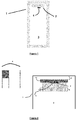
- FIG 1 an overall diagram of a container 1 for storing and / or transporting perishable products (of conventional parallelepipedal structure, provided with an access and loading door not visible in this very schematic figure), of the type comprising a compartment cryogenic 2, suitable for receiving a mass of a cryogen, for example carbon dioxide snow, and a storage compartment 3 for the products to be preserved or transported, located in the lower part of the container, where cooling takes place by contact with the air from the product compartment with the cold plate (10 on the figure 2 ) constituting the lower part of the cryogenic compartment.
- a container 1 for storing and / or transporting perishable products of conventional parallelepipedal structure, provided with an access and loading door not visible in this very schematic figure
- a compartment cryogenic 2 suitable for receiving a mass of a cryogen, for example carbon dioxide snow
- a storage compartment 3 for the products to be preserved or transported
- FIG. 2 is a block diagram making it possible to detail and better understand one of the implementations of the invention, it is not to scale, it is a kind of zoom on the "Seebeck” part quite simply allowing better understand this part.
- the detail view on the left side of the figure 2 shows an example of a standard Seebeck module that can be used.
Landscapes
- Engineering & Computer Science (AREA)
- Chemical & Material Sciences (AREA)
- Mechanical Engineering (AREA)
- Combustion & Propulsion (AREA)
- Physics & Mathematics (AREA)
- Thermal Sciences (AREA)
- General Engineering & Computer Science (AREA)
- Chemical Kinetics & Catalysis (AREA)
Description
L'invention concerne le domaine du transport ou de la distribution des denrées alimentaires périssables et autres plats cuisinés ou aliments en contenants isothermes, ainsi que les produits thermosensibles (médicaments, vaccins,...), qu'il s'agisse par exemple de conteneurs ou de camions, où le maintien de la chaîne du froid est assuré par l'intervention d'un fluide frigorifique (gaz froid, liquide cryogénique tel l'azote liquide, neige carbonique...).The invention relates to the field of transport or distribution of perishable foodstuffs and other ready-made meals or foods in insulated containers, as well as temperature-sensitive products (drugs, vaccines, etc.), whether for example containers or trucks, where the cold chain is maintained by the intervention of a refrigerating fluid (cold gas, cryogenic liquid such as liquid nitrogen, carbon dioxide snow, etc.).
Ainsi à titre d'exemple, les cuisines centrales ou encore les centres de distribution utilisent des chariots isothermes pour transporter et distribuer des plats cuisinés ou des aliments, de leurs cuisines ou plates-formes vers les lieux de consommation : restauration hospitalière, restaurants d'entreprise, scolaires etc....Thus, for example, central kitchens or distribution centers use isothermal trolleys to transport and distribute ready-made meals or food, from their kitchens or platforms to places of consumption: hospital catering, restaurants. business, school etc ...
On ne détaillera pas ici de façon exhaustive les très nombreuses configurations de contenants et de types de refroidissement qui sont disponibles sur le marché, et notamment les types de conteneurs/chariots isothermes, avec ou sans compartiment cryogénique matérialisé, avec ou sans un réservoir ("cassette") comportant le fluide froid à insérer dans le conteneur etc...We will not detail here in an exhaustive way the very many configurations of containers and types of cooling which are available on the market, and in particular the types of containers / isothermal trolleys, with or without a materialized cryogenic compartment, with or without a tank (" cassette ") containing the cold fluid to be inserted into the container, etc.
Et de même le fluide frigorifique (gaz, liquide cryogénique, solide, qu'il s'agisse d'azote, de CO2 ou autre...) peut être déposé directement dans le contenant, ou dans un réservoir à insérer dans le contenant, ou envoyé dans un échangeur situé dans le contenant, ou encore, toujours à titre illustratif, envoyé dans une capacité, située dans le contenant lui même ou a proximité (ou encore accolé, par exemple quand le contenant est un camion), capacité à partir de laquelle on prélève du fluide pour l'envoyer vers le contenant, vers un réservoir situé dans le contenant, ou vers un échangeur situé dans le contenant etc....Similarly, the refrigerating fluid (gas, cryogenic liquid, solid, whether it is nitrogen, CO 2 or other ...) can be deposited directly into the container, or in a tank to be inserted into the container. , or sent in an exchanger located in the container, or again, still for illustration, sent in a capacity, located in the container itself or nearby (or even attached, for example when the container is a truck), capacity to from which fluid is taken to send it to the container, to a reservoir located in the container, or to an exchanger located in the container, etc.
On le voit à la lecture de ce qui précède les situations et configurations sont très variées.As can be seen from the above, the situations and configurations are very varied.
A titre illustratif on peut néanmoins signaler que les chariots/conteneurs cryogéniques sont très souvent de forme parallélépipédique, ils comprennent très souvent un compartiment cryogénique disposé dans la partie supérieure du conteneur, au-dessus du compartiment de stockage où sont disposés les produits devant être conservés à température contrôlée, et traditionnellement, ce compartiment supérieur reçoit un réservoir destiné à contenir un produit réfrigérant, par exemple du dioxyde de carbone en phase solide, dont la sublimation libère des gaz froids, compensant les entrées de chaleur à travers les joints entre le conteneur et sa porte ou encore à travers les parois isolantes du conteneur. Les plats cuisinés (ou autres produits périssables) sont alors logés dans le compartiment de stockage des produits de ces conteneurs isothermes, qui sont eux même transportés dans des camions vers le site utilisateur (hôpital, cantine scolaire, officine etc......).By way of illustration, it can nevertheless be pointed out that the cryogenic trolleys / containers are very often of parallelepipedal shape, they very often include a cryogenic compartment arranged in the upper part of the container, above the storage compartment. storage where the products to be kept at a controlled temperature are placed, and traditionally, this upper compartment receives a reservoir intended to contain a refrigerant, for example carbon dioxide in solid phase, the sublimation of which releases cold gases, compensating for the entries heat through the joints between the container and its door or through the insulating walls of the container. The ready meals (or other perishable products) are then housed in the product storage compartment of these isothermal containers, which are themselves transported in trucks to the user site (hospital, school canteen, dispensary etc ...... ).
Le refroidissement a lieu par contact de l'air avec la plaque froide inférieure du compartiment cryogénique ou par le fait que la face inférieure du compartiment est « ajourée » pour laisser passer du gaz froid vers le compartiment produits.Cooling takes place by air contact with the lower cold plate of the cryogenic compartment or by the fact that the lower face of the compartment is "perforated" to allow cold gas to pass to the product compartment.
Selon les versions, le compartiment cryogénique comprend un écran thermique permettant de protéger les denrées stockées.Depending on the version, the cryogenic compartment includes a heat shield to protect the stored food.
Les phases de fonctionnement de tels conteneurs sont en général les suivantes :
- 1- lors de la mise en route du système frigorifique après chargement (par exemple au démarrage d'une tournée ou encore après une ouverture de porte), on adopte un mode de « descente rapide » en température (cette industrie nomme cette phase « pull-down »).
- 2- Une fois la température de consigne atteinte dans la chambre de stockage des produits, on adopte un mode de contrôle/régulation qui permet de maintenir la température de la chambre de stockage des produits à une valeur de consigne (phase traditionnellement appelée phase de «maintien»).
- 1- when starting up the refrigeration system after loading (for example at the start of a tour or after opening the door), a mode of "rapid descent" in temperature is adopted (this industry calls this phase "pull -down ”).
- 2- Once the setpoint temperature has been reached in the product storage chamber, a control / regulation mode is adopted which makes it possible to maintain the temperature of the products storage chamber at a set value (phase traditionally called the "phase of" maintenance ”).
On sait bien que la réglementation en vigueur concernant le respect de la chaîne du froid pour le transport des denrées alimentaires périssables devient de plus en plus rigoureuse, et conduit notamment les acteurs de telles distributions d'aliments à évoluer en terme de préparation et de traçabilité des produits à transporter.It is well known that the regulations in force concerning the respect of the cold chain for the transport of perishable foodstuffs are becoming more and more rigorous, and in particular leading the actors of such food distributions to evolve in terms of preparation and traceability. products to be transported.
Le document
Les expérimentations menées à bien par la Demanderesse ont permis de démontrer :
- d'une part que les temps de descente en température de tels conteneurs ou chariots, après le chargement du cryogène, sont particulièrement longs, souvent plusieurs heures, et
- d'autre part que les échanges thermiques dans de tels systèmes sont loin d'être optimisés.
- on the one hand that the temperature drop times of such containers or trolleys, after loading the cryogen, are particularly long, often several hours, and
- on the other hand, that the heat exchanges in such systems are far from being optimized.
Un des objectifs de la présente invention est alors de proposer une solution aux problèmes listés ci-dessus.One of the objectives of the present invention is therefore to propose a solution to the problems listed above.
Comme on le verra plus en détails dans ce qui suit, la présente invention propose alors de mettre en œuvre les moyens suivants :
- la mise en œuvre d'un (ou plusieurs) ventilateur(s) qui va créer une convection forcée dans le compartiment produit, ce ventilateur étant préférentiellement mis en œuvre uniquement durant les phases de « descente rapide » ;
- la mise en œuvre d'un (ou plusieurs) module(s) « Seebeck », exploitant la différence de température entre le cryogène (par exemple -80°C quand il s'agit de neige carbonique) et la température ambiante initiale dans l'air du chariot au démarrage du processus de refroidissement, permettant la génération d'une tension, tout particulièrement utile pour l'alimentation électrique du ou des ventilateurs en question. Les expérimentations menées par la Demanderesse ont démontré que l'arrêt du ou des ventilateurs est généralement autonome dès lors que la tension générée n'est plus suffisante pour activer ce (ces) ventilateurs, ce qui est généralement le cas en fin de « descente rapide ».
- the use of one (or more) fan (s) which will create forced convection in the product compartment, this fan preferably being used only during the “rapid descent” phases;
- the implementation of one (or more) "Seebeck" module (s), exploiting the temperature difference between the cryogen (for example -80 ° C when it is carbon dioxide snow) and the initial ambient temperature in the air from the carriage at the start of the cooling process, allowing the generation of a voltage, particularly useful for the power supply of the fan (s) in question. The experiments carried out by the Applicant have shown that the stopping of the fan (s) is generally autonomous when the voltage generated is no longer sufficient to activate this (these) fans, which is generally the case at the end of "rapid descent. ".
On comprend en effet que au fur et à mesure que la température ambiante diminue dans le compartiment produits (« pull-down ») alors le gradient de température diminue, ce qui fait diminuer la tension générée, ce qui progressivement va provoquer l'arrêt du (des) ventilateur(s) naturellement, et donc permettre une gestion autonome de la ventilation.It is in fact understood that as the ambient temperature decreases in the product compartment ("pull-down") then the temperature gradient decreases, which causes the voltage generated to decrease, which gradually will stop the (des) fan (s) naturally, and therefore allow autonomous management of ventilation.
On comprend donc que dans certains cas, le (les) ventilateur(s) peut s'arrêter avant la fin de la phase de descente rapide, la phase se poursuit alors sans l'aide de la convection forcée mais par convection naturelle, donc en quelque sorte comme dans l'art antérieur i.e par échange entre l'air refroidi à proximité de la plaque froide qui forme le bas du compartiment cryogénique, et celui plus éloigné au sein du compartiment des produits.It is therefore understood that in certain cases, the fan (s) may stop before the end of the rapid descent phase, the phase then continues without the aid of forced convection but by natural convection, therefore in sort of like in the prior art, ie by exchange between the cooled air near the cold plate which forms the bottom of the cryogenic compartment, and that further away within the product compartment.
Selon un des modes de mise en œuvre avantageux de l'invention, le chariot est équipé de moyens permettant la mise en place d'un effet radiatif au sein du compartiment produits, par exemple par la présence de plaques métalliques ou d'un revêtement à faible émissivité (peinture...) sur tout ou partie des murs verticaux du chariot, rayonnement tout particulièrement avantageux durant la phase de « maintien ».According to one of the advantageous embodiments of the invention, the carriage is equipped with means allowing the establishment of a radiative effect within the product compartment, for example by the presence of metal plates or a coating with low emissivity (paint, etc.) on all or part of the vertical walls of the carriage, particularly advantageous radiation during the "maintenance" phase.
Selon un des modes de mise en œuvre de l'invention, l'effet « Seebeck » est obtenu en mettant en œuvre :
- un coté « froid » qui est une surface métallique (par exemple en cuivre, en aluminium ou encore en inox) en contact avec la source froide (i.e l'apport cryogénique) par exemple avec la plaque froide qui forme le bas du compartiment cryogénique ou l'une de ses surfaces latérales; et
- un côté « chaud » qui est assuré par la température du compartiment produits, température qui est préférentiellement maintenue par dissipation du froid à l'aide d'un radiateur par échange avec l'air régnant dans le compartiment produits.
- a "cold" side which is a metal surface (for example copper, aluminum or even stainless steel) in contact with the cold source (ie the cryogenic supply) for example with the cold plate which forms the bottom of the cryogenic compartment or one of its side surfaces; and
- a “hot” side which is provided by the temperature of the product compartment, a temperature which is preferably maintained by dissipation of the cold using a radiator by exchange with the air prevailing in the product compartment.
D'autres caractéristiques et avantages ressortiront de la description suivante, donnée uniquement à titre d'exemple et faite en référence aux
On reconnaît sur la
On note sur cette figure la localisation d'un module « Seebeck » 4, que nous détaillerons dans le cadre de la
Notons que cette
On reconnait sur cette
La vue de détails sur la partie gauche de la
On note également la présence d'un radiateur 6, permettant la dissipation du froid et ainsi l'abaissement et/ou le maintien d'une température dans le compartiment produits.We also note the presence of a
Les expérimentations menées à bien par la Demanderesse ont permis de démontrer qu'un conteneur conforme à l'invention, combinant la présence du ventilateur et du transfert radiatif, a permis d'atteindre les résultats suivants :
- une augmentation de la vitesse de descente en température du compartiment produits, après chargement du cryogène, voisine de +17% .
- une réduction de la durée de la phase de « descente rapide » voisine de 45mn .
- s'agissant de la phase de maintien, une augmentation de la durée de cette phase (donc de la stabilité de la température au voisinage de la consigne souhaitée) voisine de +58%.
- globalement une consommation de neige carbonique diminuée d'au moins 22%, pour une performance en maintien augmentée de 58 % comme signalé ci-dessus.
- an increase in the temperature drop rate of the product compartment, after loading the cryogen, close to + 17%.
- a reduction in the duration of the “rapid descent” phase of around 45 minutes.
- with regard to the maintenance phase, an increase in the duration of this phase (therefore in the stability of the temperature in the vicinity of the desired setpoint) of around + 58%.
- overall, carbon dioxide snow consumption reduced by at least 22%, for a maintenance performance increased by 58% as indicated above.
Cette masse plus faible de cryogène embarqué permet par ailleurs d'augmenter d'autant la charge utile transportée et a un effet bénéfique direct sur le cout de la solution technique proposée ici.This lower mass of onboard cryogen also makes it possible to increase the transported payload by the same amount and has a direct beneficial effect on the cost of the technical solution proposed here.
Claims (5)
- Insulated container (1) for preserving and/or transporting perishable or heat-sensitive products, of the type comprising a cryogenic compartment (2), capable of receiving a mass of a cryogen, for example, dry ice, and a compartment for storing products (3) to be preserved or transported, where the cooling occurs by contact of air of the compartment for storing products with a cold plate (10) constituting the lower portion of the cryogenic compartment, the insulating container comprising at least one fan (5), positioned within the compartment for storing products in order to be able to create a forced convection in the compartment for storing products;
characterised in that the insulated container further comprises at least one "Seebeck" module (4), utilising the temperature difference between said mass of cryogen and the ambient temperature in the air of the compartment for storing products, allowing the generation of a voltage which can be used for the electric supply of the fan(s), the "Seebeck" effect being obtained by implementing:- a "cold" side which is a metal surface, constituting a portion of the "Seebeck" module, and which is in contact with the cold source formed by the mass of cryogen, for example by being in contact with the cold plate (10) constituting the lower portion of the cryogenic compartment or with one of the side surfaces of this cryogenic compartment;- a "hot" side which is provided by the temperature of the atmosphere within the compartment for storing products. - Container according to claim 1, characterised in that it comprises, within the compartment for storing products, a radiator (6), allowing the dissipation of the cold and thus the lowering and/or the maintaining of a temperature in the compartment for storing products.
- Container according to one of the preceding claims, characterised in that the cryogenic compartment is capable of housing a cryogenic tank, which can be loaded with said mass of cryogen.
- Container according to one of the preceding claims, characterised in that it is provided with means allowing the implementation of a radiative effect within the compartment for storing products, for example by the presence of metal plates or a coating with low emissivity over all or part of the vertical walls of the container.
- Container according to one of the preceding claims, characterised in that the fan(s) is/are used only during "rapid descent" phases of the temperature within the compartment for storing products.
Applications Claiming Priority (1)
| Application Number | Priority Date | Filing Date | Title |
|---|---|---|---|
| FR1761996A FR3074884B1 (en) | 2017-12-12 | 2017-12-12 | ISOTHERMAL CONTAINER FOR PRESERVATION AND / OR TRANSPORT OF PERISHABLE OR THERMOSENSITIVE PRODUCTS |
Publications (2)
| Publication Number | Publication Date |
|---|---|
| EP3499155A1 EP3499155A1 (en) | 2019-06-19 |
| EP3499155B1 true EP3499155B1 (en) | 2020-12-30 |
Family
ID=61028026
Family Applications (1)
| Application Number | Title | Priority Date | Filing Date |
|---|---|---|---|
| EP18208876.5A Active EP3499155B1 (en) | 2017-12-12 | 2018-11-28 | Insulated container for preserving and/or transporting perishable or heat-sensitive products |
Country Status (3)
| Country | Link |
|---|---|
| US (1) | US20190241348A1 (en) |
| EP (1) | EP3499155B1 (en) |
| FR (1) | FR3074884B1 (en) |
Citations (1)
| Publication number | Priority date | Publication date | Assignee | Title |
|---|---|---|---|---|
| KR101682553B1 (en) * | 2015-09-16 | 2016-12-05 | 한국식품연구원 | Three temperature chain system vehicle |
Family Cites Families (5)
| Publication number | Priority date | Publication date | Assignee | Title |
|---|---|---|---|---|
| JP2003156272A (en) * | 2001-11-17 | 2003-05-30 | Yasuhiro Murata | Cold reserving system using refrigerant |
| US8567211B2 (en) * | 2010-02-17 | 2013-10-29 | Hafeth A. Al-Rasheed | Portable hygenic ice chest for medical supplies or the like |
| US9862496B2 (en) * | 2012-03-30 | 2018-01-09 | B/E Aerospace, Inc. | Aircraft galley chiller system |
| DE102016107813B3 (en) * | 2016-04-27 | 2017-05-04 | Verein zur Förderung innovativer Verfahren in der Logistik, VVL e.V. | Reusable transport box |
| WO2018169890A1 (en) * | 2017-03-16 | 2018-09-20 | Systems And Software Enterprises, Llc | Power source for a vehicle service cart |
-
2017
- 2017-12-12 FR FR1761996A patent/FR3074884B1/en not_active Expired - Fee Related
-
2018
- 2018-11-28 EP EP18208876.5A patent/EP3499155B1/en active Active
- 2018-12-11 US US16/216,429 patent/US20190241348A1/en not_active Abandoned
Patent Citations (1)
| Publication number | Priority date | Publication date | Assignee | Title |
|---|---|---|---|---|
| KR101682553B1 (en) * | 2015-09-16 | 2016-12-05 | 한국식품연구원 | Three temperature chain system vehicle |
Also Published As
| Publication number | Publication date |
|---|---|
| FR3074884B1 (en) | 2019-11-22 |
| FR3074884A1 (en) | 2019-06-14 |
| US20190241348A1 (en) | 2019-08-08 |
| EP3499155A1 (en) | 2019-06-19 |
Similar Documents
| Publication | Publication Date | Title |
|---|---|---|
| CA1319347C (en) | Isothermal container with coolant tank and application thereof in the transportation of fresh goods | |
| US7310967B2 (en) | Temperature controlled container | |
| US20180259230A1 (en) | Portable instant cooling system with controlled temperature obtained through timed-release liquid or gaseous co2 coolant for general refrigeration use in mobile and stationary containers | |
| US20100024439A1 (en) | Cooling Device | |
| KR101389531B1 (en) | Thermoelectric element-applied apparatus for transporting and delivering agrifood | |
| US10279991B2 (en) | Rigid refrigerated offshore shipping container | |
| CA2964651A1 (en) | Passive refrigeration system for the cold chain industry | |
| US4457142A (en) | Method of chilling materials and chilling container | |
| EP3499155B1 (en) | Insulated container for preserving and/or transporting perishable or heat-sensitive products | |
| EP2516943A1 (en) | Device for transporting and distributing heat-sensitive products | |
| Margeirsson et al. | Optimised chilling protocols for fresh fish | |
| EP1934537B1 (en) | Dual-compartment carbon dioxide snow receptacle for isothermal containers | |
| US1921147A (en) | Method of and means for controlling low temperature refrigerants | |
| FR2916189A1 (en) | DEVICE FOR TRANSPORTING AND DISPENSING THERMOSENSITIVE PRODUCTS | |
| ES2662820T3 (en) | Cooling box and method to transport heat sensitive products in a transport vehicle and / or to distribute products to end customers | |
| US10830519B2 (en) | Cooling by dry ice during transportation | |
| KR101608057B1 (en) | Temperature control method for storage and transport container | |
| EP2996967A1 (en) | Container for storing and transporting heat-sensitive products | |
| CN107003056B (en) | Cooling apparatus and method | |
| US7159404B2 (en) | System and method for storing a product in a thermally stabilized state | |
| FR3062713A1 (en) | THERMAL FLOW SWITCH FROM A CARBON FLOW RESERVE AND IN PARTICULAR A TEMPERATURE REGULATING DEVICE FOR CARBONIC SNOW-COOLED CONTAINERS | |
| JPH0123100Y2 (en) | ||
| US20180274824A1 (en) | Portable instant cooling system with controlled temperature obtained through timed-release liquid or gaseous co2 coolant for general refrigeration use in mobile and stationary containers | |
| FR3012091A1 (en) | SYSTEM FOR CONFINING THE BODY OF A REFRIGERATION TRUCK USING LATERAL AIR CURTAINS | |
| RU69702U1 (en) | MOBILE DEVICE FOR COOLING AND TRANSPORTATION OF FLUID FOOD PRODUCTS |
Legal Events
| Date | Code | Title | Description |
|---|---|---|---|
| PUAI | Public reference made under article 153(3) epc to a published international application that has entered the european phase |
Free format text: ORIGINAL CODE: 0009012 |
|
| STAA | Information on the status of an ep patent application or granted ep patent |
Free format text: STATUS: THE APPLICATION HAS BEEN PUBLISHED |
|
| AK | Designated contracting states |
Kind code of ref document: A1 Designated state(s): AL AT BE BG CH CY CZ DE DK EE ES FI FR GB GR HR HU IE IS IT LI LT LU LV MC MK MT NL NO PL PT RO RS SE SI SK SM TR |
|
| AX | Request for extension of the european patent |
Extension state: BA ME |
|
| STAA | Information on the status of an ep patent application or granted ep patent |
Free format text: STATUS: REQUEST FOR EXAMINATION WAS MADE |
|
| 17P | Request for examination filed |
Effective date: 20191219 |
|
| RBV | Designated contracting states (corrected) |
Designated state(s): AL AT BE BG CH CY CZ DE DK EE ES FI FR GB GR HR HU IE IS IT LI LT LU LV MC MK MT NL NO PL PT RO RS SE SI SK SM TR |
|
| RIC1 | Information provided on ipc code assigned before grant |
Ipc: F25D 3/06 20060101AFI20200512BHEP Ipc: H01L 35/00 20060101ALI20200512BHEP |
|
| GRAP | Despatch of communication of intention to grant a patent |
Free format text: ORIGINAL CODE: EPIDOSNIGR1 |
|
| STAA | Information on the status of an ep patent application or granted ep patent |
Free format text: STATUS: GRANT OF PATENT IS INTENDED |
|
| INTG | Intention to grant announced |
Effective date: 20200622 |
|
| GRAS | Grant fee paid |
Free format text: ORIGINAL CODE: EPIDOSNIGR3 |
|
| GRAA | (expected) grant |
Free format text: ORIGINAL CODE: 0009210 |
|
| STAA | Information on the status of an ep patent application or granted ep patent |
Free format text: STATUS: THE PATENT HAS BEEN GRANTED |
|
| AK | Designated contracting states |
Kind code of ref document: B1 Designated state(s): AL AT BE BG CH CY CZ DE DK EE ES FI FR GB GR HR HU IE IS IT LI LT LU LV MC MK MT NL NO PL PT RO RS SE SI SK SM TR |
|
| REG | Reference to a national code |
Ref country code: GB Ref legal event code: FG4D Free format text: NOT ENGLISH |
|
| REG | Reference to a national code |
Ref country code: AT Ref legal event code: REF Ref document number: 1350342 Country of ref document: AT Kind code of ref document: T Effective date: 20210115 |
|
| REG | Reference to a national code |
Ref country code: DE Ref legal event code: R096 Ref document number: 602018011322 Country of ref document: DE |
|
| REG | Reference to a national code |
Ref country code: IE Ref legal event code: FG4D Free format text: LANGUAGE OF EP DOCUMENT: FRENCH |
|
| PG25 | Lapsed in a contracting state [announced via postgrant information from national office to epo] |
Ref country code: NO Free format text: LAPSE BECAUSE OF FAILURE TO SUBMIT A TRANSLATION OF THE DESCRIPTION OR TO PAY THE FEE WITHIN THE PRESCRIBED TIME-LIMIT Effective date: 20210330 Ref country code: GR Free format text: LAPSE BECAUSE OF FAILURE TO SUBMIT A TRANSLATION OF THE DESCRIPTION OR TO PAY THE FEE WITHIN THE PRESCRIBED TIME-LIMIT Effective date: 20210331 Ref country code: FI Free format text: LAPSE BECAUSE OF FAILURE TO SUBMIT A TRANSLATION OF THE DESCRIPTION OR TO PAY THE FEE WITHIN THE PRESCRIBED TIME-LIMIT Effective date: 20201230 Ref country code: RS Free format text: LAPSE BECAUSE OF FAILURE TO SUBMIT A TRANSLATION OF THE DESCRIPTION OR TO PAY THE FEE WITHIN THE PRESCRIBED TIME-LIMIT Effective date: 20201230 |
|
| REG | Reference to a national code |
Ref country code: AT Ref legal event code: MK05 Ref document number: 1350342 Country of ref document: AT Kind code of ref document: T Effective date: 20201230 |
|
| PG25 | Lapsed in a contracting state [announced via postgrant information from national office to epo] |
Ref country code: BG Free format text: LAPSE BECAUSE OF FAILURE TO SUBMIT A TRANSLATION OF THE DESCRIPTION OR TO PAY THE FEE WITHIN THE PRESCRIBED TIME-LIMIT Effective date: 20210330 Ref country code: LV Free format text: LAPSE BECAUSE OF FAILURE TO SUBMIT A TRANSLATION OF THE DESCRIPTION OR TO PAY THE FEE WITHIN THE PRESCRIBED TIME-LIMIT Effective date: 20201230 Ref country code: SE Free format text: LAPSE BECAUSE OF FAILURE TO SUBMIT A TRANSLATION OF THE DESCRIPTION OR TO PAY THE FEE WITHIN THE PRESCRIBED TIME-LIMIT Effective date: 20201230 |
|
| REG | Reference to a national code |
Ref country code: NL Ref legal event code: MP Effective date: 20201230 |
|
| PG25 | Lapsed in a contracting state [announced via postgrant information from national office to epo] |
Ref country code: HR Free format text: LAPSE BECAUSE OF FAILURE TO SUBMIT A TRANSLATION OF THE DESCRIPTION OR TO PAY THE FEE WITHIN THE PRESCRIBED TIME-LIMIT Effective date: 20201230 |
|
| REG | Reference to a national code |
Ref country code: LT Ref legal event code: MG9D |
|
| PG25 | Lapsed in a contracting state [announced via postgrant information from national office to epo] |
Ref country code: SK Free format text: LAPSE BECAUSE OF FAILURE TO SUBMIT A TRANSLATION OF THE DESCRIPTION OR TO PAY THE FEE WITHIN THE PRESCRIBED TIME-LIMIT Effective date: 20201230 Ref country code: CZ Free format text: LAPSE BECAUSE OF FAILURE TO SUBMIT A TRANSLATION OF THE DESCRIPTION OR TO PAY THE FEE WITHIN THE PRESCRIBED TIME-LIMIT Effective date: 20201230 Ref country code: EE Free format text: LAPSE BECAUSE OF FAILURE TO SUBMIT A TRANSLATION OF THE DESCRIPTION OR TO PAY THE FEE WITHIN THE PRESCRIBED TIME-LIMIT Effective date: 20201230 Ref country code: RO Free format text: LAPSE BECAUSE OF FAILURE TO SUBMIT A TRANSLATION OF THE DESCRIPTION OR TO PAY THE FEE WITHIN THE PRESCRIBED TIME-LIMIT Effective date: 20201230 Ref country code: PT Free format text: LAPSE BECAUSE OF FAILURE TO SUBMIT A TRANSLATION OF THE DESCRIPTION OR TO PAY THE FEE WITHIN THE PRESCRIBED TIME-LIMIT Effective date: 20210430 Ref country code: LT Free format text: LAPSE BECAUSE OF FAILURE TO SUBMIT A TRANSLATION OF THE DESCRIPTION OR TO PAY THE FEE WITHIN THE PRESCRIBED TIME-LIMIT Effective date: 20201230 |
|
| PG25 | Lapsed in a contracting state [announced via postgrant information from national office to epo] |
Ref country code: AT Free format text: LAPSE BECAUSE OF FAILURE TO SUBMIT A TRANSLATION OF THE DESCRIPTION OR TO PAY THE FEE WITHIN THE PRESCRIBED TIME-LIMIT Effective date: 20201230 Ref country code: PL Free format text: LAPSE BECAUSE OF FAILURE TO SUBMIT A TRANSLATION OF THE DESCRIPTION OR TO PAY THE FEE WITHIN THE PRESCRIBED TIME-LIMIT Effective date: 20201230 |
|
| PG25 | Lapsed in a contracting state [announced via postgrant information from national office to epo] |
Ref country code: IS Free format text: LAPSE BECAUSE OF FAILURE TO SUBMIT A TRANSLATION OF THE DESCRIPTION OR TO PAY THE FEE WITHIN THE PRESCRIBED TIME-LIMIT Effective date: 20210430 |
|
| REG | Reference to a national code |
Ref country code: DE Ref legal event code: R097 Ref document number: 602018011322 Country of ref document: DE |
|
| PG25 | Lapsed in a contracting state [announced via postgrant information from national office to epo] |
Ref country code: AL Free format text: LAPSE BECAUSE OF FAILURE TO SUBMIT A TRANSLATION OF THE DESCRIPTION OR TO PAY THE FEE WITHIN THE PRESCRIBED TIME-LIMIT Effective date: 20201230 Ref country code: IT Free format text: LAPSE BECAUSE OF FAILURE TO SUBMIT A TRANSLATION OF THE DESCRIPTION OR TO PAY THE FEE WITHIN THE PRESCRIBED TIME-LIMIT Effective date: 20201230 |
|
| PLBE | No opposition filed within time limit |
Free format text: ORIGINAL CODE: 0009261 |
|
| STAA | Information on the status of an ep patent application or granted ep patent |
Free format text: STATUS: NO OPPOSITION FILED WITHIN TIME LIMIT |
|
| PG25 | Lapsed in a contracting state [announced via postgrant information from national office to epo] |
Ref country code: DK Free format text: LAPSE BECAUSE OF FAILURE TO SUBMIT A TRANSLATION OF THE DESCRIPTION OR TO PAY THE FEE WITHIN THE PRESCRIBED TIME-LIMIT Effective date: 20201230 |
|
| 26N | No opposition filed |
Effective date: 20211001 |
|
| PG25 | Lapsed in a contracting state [announced via postgrant information from national office to epo] |
Ref country code: ES Free format text: LAPSE BECAUSE OF FAILURE TO SUBMIT A TRANSLATION OF THE DESCRIPTION OR TO PAY THE FEE WITHIN THE PRESCRIBED TIME-LIMIT Effective date: 20201230 |
|
| PG25 | Lapsed in a contracting state [announced via postgrant information from national office to epo] |
Ref country code: SI Free format text: LAPSE BECAUSE OF FAILURE TO SUBMIT A TRANSLATION OF THE DESCRIPTION OR TO PAY THE FEE WITHIN THE PRESCRIBED TIME-LIMIT Effective date: 20201230 |
|
| PG25 | Lapsed in a contracting state [announced via postgrant information from national office to epo] |
Ref country code: IS Free format text: LAPSE BECAUSE OF FAILURE TO SUBMIT A TRANSLATION OF THE DESCRIPTION OR TO PAY THE FEE WITHIN THE PRESCRIBED TIME-LIMIT Effective date: 20210430 |
|
| PG25 | Lapsed in a contracting state [announced via postgrant information from national office to epo] |
Ref country code: MC Free format text: LAPSE BECAUSE OF FAILURE TO SUBMIT A TRANSLATION OF THE DESCRIPTION OR TO PAY THE FEE WITHIN THE PRESCRIBED TIME-LIMIT Effective date: 20201230 |
|
| REG | Reference to a national code |
Ref country code: CH Ref legal event code: PL |
|
| PG25 | Lapsed in a contracting state [announced via postgrant information from national office to epo] |
Ref country code: LU Free format text: LAPSE BECAUSE OF NON-PAYMENT OF DUE FEES Effective date: 20211128 Ref country code: BE Free format text: LAPSE BECAUSE OF NON-PAYMENT OF DUE FEES Effective date: 20211130 |
|
| REG | Reference to a national code |
Ref country code: BE Ref legal event code: MM Effective date: 20211130 |
|
| PG25 | Lapsed in a contracting state [announced via postgrant information from national office to epo] |
Ref country code: LI Free format text: LAPSE BECAUSE OF NON-PAYMENT OF DUE FEES Effective date: 20211130 Ref country code: CH Free format text: LAPSE BECAUSE OF NON-PAYMENT OF DUE FEES Effective date: 20211130 |
|
| PG25 | Lapsed in a contracting state [announced via postgrant information from national office to epo] |
Ref country code: IE Free format text: LAPSE BECAUSE OF NON-PAYMENT OF DUE FEES Effective date: 20211128 |
|
| PGFP | Annual fee paid to national office [announced via postgrant information from national office to epo] |
Ref country code: DE Payment date: 20221123 Year of fee payment: 5 |
|
| PG25 | Lapsed in a contracting state [announced via postgrant information from national office to epo] |
Ref country code: NL Free format text: LAPSE BECAUSE OF NON-PAYMENT OF DUE FEES Effective date: 20201230 Ref country code: CY Free format text: LAPSE BECAUSE OF FAILURE TO SUBMIT A TRANSLATION OF THE DESCRIPTION OR TO PAY THE FEE WITHIN THE PRESCRIBED TIME-LIMIT Effective date: 20201230 |
|
| GBPC | Gb: european patent ceased through non-payment of renewal fee |
Effective date: 20221128 |
|
| PG25 | Lapsed in a contracting state [announced via postgrant information from national office to epo] |
Ref country code: SM Free format text: LAPSE BECAUSE OF FAILURE TO SUBMIT A TRANSLATION OF THE DESCRIPTION OR TO PAY THE FEE WITHIN THE PRESCRIBED TIME-LIMIT Effective date: 20201230 Ref country code: HU Free format text: LAPSE BECAUSE OF FAILURE TO SUBMIT A TRANSLATION OF THE DESCRIPTION OR TO PAY THE FEE WITHIN THE PRESCRIBED TIME-LIMIT; INVALID AB INITIO Effective date: 20181128 |
|
| PG25 | Lapsed in a contracting state [announced via postgrant information from national office to epo] |
Ref country code: GB Free format text: LAPSE BECAUSE OF NON-PAYMENT OF DUE FEES Effective date: 20221128 |
|
| PGFP | Annual fee paid to national office [announced via postgrant information from national office to epo] |
Ref country code: FR Payment date: 20231120 Year of fee payment: 6 |
|
| PG25 | Lapsed in a contracting state [announced via postgrant information from national office to epo] |
Ref country code: MK Free format text: LAPSE BECAUSE OF FAILURE TO SUBMIT A TRANSLATION OF THE DESCRIPTION OR TO PAY THE FEE WITHIN THE PRESCRIBED TIME-LIMIT Effective date: 20201230 |
|
| REG | Reference to a national code |
Ref country code: DE Ref legal event code: R119 Ref document number: 602018011322 Country of ref document: DE |
|
| PG25 | Lapsed in a contracting state [announced via postgrant information from national office to epo] |
Ref country code: TR Free format text: LAPSE BECAUSE OF FAILURE TO SUBMIT A TRANSLATION OF THE DESCRIPTION OR TO PAY THE FEE WITHIN THE PRESCRIBED TIME-LIMIT Effective date: 20201230 |