EP3499140B1 - Luftaufbereitungsanlage mit doppelströmung und angemessener trocknung für gebäude mit wasseraktivitäten, sowie verfahren zum steuern einer solchen anlage - Google Patents
Luftaufbereitungsanlage mit doppelströmung und angemessener trocknung für gebäude mit wasseraktivitäten, sowie verfahren zum steuern einer solchen anlage Download PDFInfo
- Publication number
- EP3499140B1 EP3499140B1 EP18211607.9A EP18211607A EP3499140B1 EP 3499140 B1 EP3499140 B1 EP 3499140B1 EP 18211607 A EP18211607 A EP 18211607A EP 3499140 B1 EP3499140 B1 EP 3499140B1
- Authority
- EP
- European Patent Office
- Prior art keywords
- air
- heat exchanger
- zone
- blowing
- heating
- Prior art date
- Legal status (The legal status is an assumption and is not a legal conclusion. Google has not performed a legal analysis and makes no representation as to the accuracy of the status listed.)
- Active
Links
Images
Classifications
-
- F—MECHANICAL ENGINEERING; LIGHTING; HEATING; WEAPONS; BLASTING
- F24—HEATING; RANGES; VENTILATING
- F24F—AIR-CONDITIONING; AIR-HUMIDIFICATION; VENTILATION; USE OF AIR CURRENTS FOR SCREENING
- F24F5/00—Air-conditioning systems or apparatus not covered by F24F1/00 or F24F3/00, e.g. using solar heat or combined with household units such as an oven or water heater
- F24F5/0071—Air-conditioning systems or apparatus not covered by F24F1/00 or F24F3/00, e.g. using solar heat or combined with household units such as an oven or water heater adapted for use in covered swimming pools
-
- F—MECHANICAL ENGINEERING; LIGHTING; HEATING; WEAPONS; BLASTING
- F24—HEATING; RANGES; VENTILATING
- F24F—AIR-CONDITIONING; AIR-HUMIDIFICATION; VENTILATION; USE OF AIR CURRENTS FOR SCREENING
- F24F12/00—Use of energy recovery systems in air conditioning, ventilation or screening
- F24F12/001—Use of energy recovery systems in air conditioning, ventilation or screening with heat-exchange between supplied and exhausted air
- F24F12/002—Use of energy recovery systems in air conditioning, ventilation or screening with heat-exchange between supplied and exhausted air using an intermediate heat-transfer fluid
- F24F12/003—Use of energy recovery systems in air conditioning, ventilation or screening with heat-exchange between supplied and exhausted air using an intermediate heat-transfer fluid using a heat pump
-
- F—MECHANICAL ENGINEERING; LIGHTING; HEATING; WEAPONS; BLASTING
- F24—HEATING; RANGES; VENTILATING
- F24F—AIR-CONDITIONING; AIR-HUMIDIFICATION; VENTILATION; USE OF AIR CURRENTS FOR SCREENING
- F24F12/00—Use of energy recovery systems in air conditioning, ventilation or screening
- F24F12/001—Use of energy recovery systems in air conditioning, ventilation or screening with heat-exchange between supplied and exhausted air
- F24F12/006—Use of energy recovery systems in air conditioning, ventilation or screening with heat-exchange between supplied and exhausted air using an air-to-air heat exchanger
-
- F—MECHANICAL ENGINEERING; LIGHTING; HEATING; WEAPONS; BLASTING
- F24—HEATING; RANGES; VENTILATING
- F24F—AIR-CONDITIONING; AIR-HUMIDIFICATION; VENTILATION; USE OF AIR CURRENTS FOR SCREENING
- F24F3/00—Air-conditioning systems in which conditioned primary air is supplied from one or more central stations to distributing units in the rooms or spaces where it may receive secondary treatment; Apparatus specially designed for such systems
- F24F3/12—Air-conditioning systems in which conditioned primary air is supplied from one or more central stations to distributing units in the rooms or spaces where it may receive secondary treatment; Apparatus specially designed for such systems characterised by the treatment of the air otherwise than by heating and cooling
- F24F3/14—Air-conditioning systems in which conditioned primary air is supplied from one or more central stations to distributing units in the rooms or spaces where it may receive secondary treatment; Apparatus specially designed for such systems characterised by the treatment of the air otherwise than by heating and cooling by humidification; by dehumidification
- F24F3/1411—Air-conditioning systems in which conditioned primary air is supplied from one or more central stations to distributing units in the rooms or spaces where it may receive secondary treatment; Apparatus specially designed for such systems characterised by the treatment of the air otherwise than by heating and cooling by humidification; by dehumidification by absorbing or adsorbing water, e.g. using an hygroscopic desiccant
- F24F3/1423—Air-conditioning systems in which conditioned primary air is supplied from one or more central stations to distributing units in the rooms or spaces where it may receive secondary treatment; Apparatus specially designed for such systems characterised by the treatment of the air otherwise than by heating and cooling by humidification; by dehumidification by absorbing or adsorbing water, e.g. using an hygroscopic desiccant with a moving bed of solid desiccants, e.g. a rotary wheel supporting solid desiccants
-
- F—MECHANICAL ENGINEERING; LIGHTING; HEATING; WEAPONS; BLASTING
- F24—HEATING; RANGES; VENTILATING
- F24F—AIR-CONDITIONING; AIR-HUMIDIFICATION; VENTILATION; USE OF AIR CURRENTS FOR SCREENING
- F24F3/00—Air-conditioning systems in which conditioned primary air is supplied from one or more central stations to distributing units in the rooms or spaces where it may receive secondary treatment; Apparatus specially designed for such systems
- F24F3/12—Air-conditioning systems in which conditioned primary air is supplied from one or more central stations to distributing units in the rooms or spaces where it may receive secondary treatment; Apparatus specially designed for such systems characterised by the treatment of the air otherwise than by heating and cooling
- F24F3/14—Air-conditioning systems in which conditioned primary air is supplied from one or more central stations to distributing units in the rooms or spaces where it may receive secondary treatment; Apparatus specially designed for such systems characterised by the treatment of the air otherwise than by heating and cooling by humidification; by dehumidification
- F24F3/147—Air-conditioning systems in which conditioned primary air is supplied from one or more central stations to distributing units in the rooms or spaces where it may receive secondary treatment; Apparatus specially designed for such systems characterised by the treatment of the air otherwise than by heating and cooling by humidification; by dehumidification with both heat and humidity transfer between supplied and exhausted air
-
- F—MECHANICAL ENGINEERING; LIGHTING; HEATING; WEAPONS; BLASTING
- F24—HEATING; RANGES; VENTILATING
- F24F—AIR-CONDITIONING; AIR-HUMIDIFICATION; VENTILATION; USE OF AIR CURRENTS FOR SCREENING
- F24F2203/00—Devices or apparatus used for air treatment
- F24F2203/10—Rotary wheel
-
- F—MECHANICAL ENGINEERING; LIGHTING; HEATING; WEAPONS; BLASTING
- F24—HEATING; RANGES; VENTILATING
- F24F—AIR-CONDITIONING; AIR-HUMIDIFICATION; VENTILATION; USE OF AIR CURRENTS FOR SCREENING
- F24F2203/00—Devices or apparatus used for air treatment
- F24F2203/10—Rotary wheel
- F24F2203/1032—Desiccant wheel
-
- Y—GENERAL TAGGING OF NEW TECHNOLOGICAL DEVELOPMENTS; GENERAL TAGGING OF CROSS-SECTIONAL TECHNOLOGIES SPANNING OVER SEVERAL SECTIONS OF THE IPC; TECHNICAL SUBJECTS COVERED BY FORMER USPC CROSS-REFERENCE ART COLLECTIONS [XRACs] AND DIGESTS
- Y02—TECHNOLOGIES OR APPLICATIONS FOR MITIGATION OR ADAPTATION AGAINST CLIMATE CHANGE
- Y02B—CLIMATE CHANGE MITIGATION TECHNOLOGIES RELATED TO BUILDINGS, e.g. HOUSING, HOUSE APPLIANCES OR RELATED END-USER APPLICATIONS
- Y02B30/00—Energy efficient heating, ventilation or air conditioning [HVAC]
- Y02B30/52—Heat recovery pumps, i.e. heat pump based systems or units able to transfer the thermal energy from one area of the premises or part of the facilities to a different one, improving the overall efficiency
-
- Y—GENERAL TAGGING OF NEW TECHNOLOGICAL DEVELOPMENTS; GENERAL TAGGING OF CROSS-SECTIONAL TECHNOLOGIES SPANNING OVER SEVERAL SECTIONS OF THE IPC; TECHNICAL SUBJECTS COVERED BY FORMER USPC CROSS-REFERENCE ART COLLECTIONS [XRACs] AND DIGESTS
- Y02—TECHNOLOGIES OR APPLICATIONS FOR MITIGATION OR ADAPTATION AGAINST CLIMATE CHANGE
- Y02B—CLIMATE CHANGE MITIGATION TECHNOLOGIES RELATED TO BUILDINGS, e.g. HOUSING, HOUSE APPLIANCES OR RELATED END-USER APPLICATIONS
- Y02B30/00—Energy efficient heating, ventilation or air conditioning [HVAC]
- Y02B30/56—Heat recovery units
Definitions
- the present invention relates to a dual flow air handling unit for thermal regulation and air renewal of at least one area to be treated. It relates more particularly to a desiccant air handling unit.
- the present invention finds a preferred, and non-limiting, application in the air treatment of a building for aquatic activity, such as an indoor swimming pool, and in general in the air treatment of a building having a need for temperature regulation (for example in a temperature range between 10 and 40 ° C) and humidity (for example in an absolute humidity range between 4 and 20 g / kg).
- temperature regulation for example in a temperature range between 10 and 40 ° C
- humidity for example in an absolute humidity range between 4 and 20 g / kg.
- the invention applies in particular, without limitation, to the air treatment of a building having a need for humidity regulation for atmospheres requiring constant humidification with an absolute humidity greater than 10 g / kg, and in particular included between 10 and 20 g / kg.
- the present invention aims to solve all or part of the aforementioned drawbacks, by proposing a desiccant air treatment unit which is suitable in a heating mode for blowing hot air and having a constant humidification with a higher absolute humidity. at 10 g / kg, and in particular between 10 and 20 g / kg, while limiting energy consumption.
- Another object of the invention is to propose an air treatment unit which avoids, or at least limits, a reinjection of stale air loaded with pollutants in order precisely to avoid, or at least limit, the concentration of pollutants in the fresh air supply.
- Another object of the invention is to propose an air treatment unit which meets the requirements and needs for the treatment of air in an indoor swimming pool, and in general of a building having a need for regulation in temperature and humidity for environments requiring high humidification.
- the recovery heat exchanger and the enthalpy heat exchanger are activated so that the air handling unit provides heat recovery from the exhaust air mainly by the recovery heat exchanger, and recovery of moisture from stale air by the enthalpy heat exchanger.
- the dual-flow air handling unit further comprises a return humidifier placed on the return path upstream of the enthalpy heat exchanger.
- the enthalpy heat exchanger is of the rotary type.
- the heating heating coil is placed on the blowing path downstream of the enthalpy heat exchanger and upstream of the blowing humidifier.
- the recovery heat exchanger is chosen from a recovery wheel, a cross-current exchanger, a counter-current exchanger, a counter-current plate exchanger.
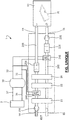
- a dual flow air handling unit 1 for thermal regulation and air renewal of at least one ZO zone to be treated, such as an activity building aquatic hosting an indoor or indoor PI pool and requiring constant humidification with a relative humidity between 10 and 20 g / kg.
- the concepts “upstream”, “downstream”, “inlet” and “outlet” systematically refer to the direction of air circulation in the channel concerned or in the element concerned.
- the input ES of the blowing channel 20S is located on the outside side EXT, while its outlet SS is located on the side of the zone ZO.
- the input ER of the recovery channel 20R is located on the side of the zone ZO, while its output SR is located on the side of the exterior EXT.
- a first element is arranged upstream of a second element on a track, when this first element is located closer to the entrance to the track than the second element.
- a first element is arranged downstream of a second element on a track, when this first element is located closer to the exit of the track than the second element.
- the desiccant wheel 21 incorporates an on / off system, such as a motorized system, in order to be able to remotely control its implementation.
- On Off the recovery heat exchanger 22 integrates an on / off system, such as a motorized system, in order to be able to remotely control its on / off.
- the enthalpy heat exchanger 26 incorporates an on / off system, such as a motorized system, in order to be able to remotely control its on / off.
- the return fan 23R can however be placed elsewhere on the return path 20R, for example upstream of the return humidifier 25R.
- the return humidifier 25R is supplied with water by a water pipe (not visible) connected to a water network (eg the building network), and on which is placed a circulation pump. water. It is also advantageous to provide, on this water pipe, a water treatment device, ranging from a simple filter to a reverse osmosis device, the technology of which will depend on the quality of the water (hardness , pH, etc.).
- At least one filter can be placed on the return path 20R, preferably upstream of the return humidifier 25R, to filter the air extracted from the zone ZO before entering the components of the control unit.
- double flow air treatment 1 can be placed on the return path 20R, preferably upstream of the return humidifier 25R, to filter the air extracted from the zone ZO before entering the components of the control unit.
- a bypass or bypass for example calibrated between 10 and 30%, can be placed between the inlet of the regenerative heating battery 24R and the outlet of the desiccant wheel 21, so that part (for example 10 to 30%) of the air leaving the recovery heat exchanger 22 is directly evacuated to the outside without passing through the regenerative heating battery 24R and the desiccant wheel 21, for reasons of capacity of the desiccant wheel 21.
- a piloted valve can possibly be positioned on this bypass in order to be able to regulate the quantity of air taken from the return path 20R.
- the blowing fan 23S can however be placed elsewhere on the blowing path 20S, for example upstream of the heating heater 24S or upstream of the blowing humidifier 25S.
- the supply air humidifier 23S is supplied with water by a water pipe connected to a water network, and on which a water circulation pump is placed. It is also advantageous to provide a water treatment device on this water pipe.
- At least one filter can be placed on the blowing path 20S, preferably upstream of the desiccant wheel 21, to filter the fresh air taken from outside EXT before entering the components of the control unit.
- double flow air treatment 1 can be placed on the blowing path 20S, preferably upstream of the desiccant wheel 21, to filter the fresh air taken from outside EXT before entering the components of the control unit.
- a thermal generator 3 is also provided in connection with the heating batteries 24R, 24S via a buffer tank 30.
- the thermal generator 3 constitutes a heat source, preferably of the durable type such as, for example, solar collectors, a device for heating the wood, a biogas unit, a household waste incineration unit, a cogeneration device, a condensing boiler, a waste heat recovery system, etc. or the combination of several separate heat sources.
- the buffer tank 30 has a hot pipe 31 and a cold pipe 32, for the circulation of a heat transfer fluid respectively heated and cooled.
- These channels 31, 32 are connected to the batteries 24R, 24S to heat the air circulating through these batteries 24R, 24S; these batteries 24R, 24S forming heat exchangers between the hot source (the hot heat transfer fluid coming from the hot pipe 31) and the air passing through the batteries 24R, 24S, the cool heat transfer fluid returning to the buffer tank via the cold pipe 32 .
- the heat transfer fluid is for example water without any particular antifreeze treatment, insofar as these channels are preferably arranged inside of a building.
- the fluid is preferably water supplemented with an antifreeze treatment (for example water with glycol) because the thermal generator 3 and these channels 36, 37 are generally located outside the building, and therefore exposed to frost.
- the hot pipe 31 is connected to an inlet of the regenerative heating battery 24R for the heat transfer fluid, and a pump is placed on this hot pipe 31 upstream of this battery 24R for the circulation of the heat transfer fluid.
- the cold pipe 32 is connected to an outlet of the regenerative heating battery 24R for the return of the heat transfer fluid in the buffer tank 30.
- the hot pipe 31 is connected to an inlet of the heating heater 24S for the heat transfer fluid, and a pump is placed on this hot pipe 31 upstream of this heating heater 24S for the circulation of the fluid. coolant.
- the cold pipe 32 is connected to an output of the heating heating coil 24S for the return of the heat transfer fluid in the buffer tank 30.
- the dual flow air handling unit 1 also includes four temperature control systems.
- the controller performs closed-loop regulation, in particular of the PID type for “proportional integral derivative”, of the temperature at the outlet of the 24R regenerative heating battery, by controlling the flow rates in the first and second channels of the motorized valve. .
- the controller performs closed loop regulation, in particular of the PID type, of the temperature at the outlet of the 24S heating coil, by controlling the flow rates in the first and second channels of the motorized valve.
- the controller performs closed-loop regulation, in particular of the PID type, of the temperature at the outlet of the return humidifier 25R, by controlling the flow rate in the channels of the motorized valve.
- the controller performs closed-loop regulation, in particular of the PID type, of the temperature at the outlet of the supply air humidifier 25S, by controlling the flow rate in the channels of the motorized valve.
- the dual-flow air handling unit 1 includes a control unit which controls part of the elements of the dual-flow air handling unit 1 described above in order to implement the process for processing air according to the invention for the thermal regulation and the air renewal of the zone ZO.
Landscapes
- Engineering & Computer Science (AREA)
- Chemical & Material Sciences (AREA)
- Combustion & Propulsion (AREA)
- Mechanical Engineering (AREA)
- General Engineering & Computer Science (AREA)
- Life Sciences & Earth Sciences (AREA)
- Sustainable Development (AREA)
- Central Air Conditioning (AREA)
- Drying Of Gases (AREA)
- Greenhouses (AREA)
Claims (9)
- Luftaufbereitungsanlage mit Doppelströmung (1) zur Wärmeregelung und Lufterneuerung mindestens einer aufzubereitenden Zone (ZO), wobei die Luftaufbereitungsanlage mit Doppelströmung (1) eine Luftaufbereitungsanlage mit Trocknung ist, die mindestens Folgendes beinhaltet:- zwei Luftzirkulationskanäle zwischen der Zone (ZO) und dem Außenbereich (EXT), einen Wiederaufnahmekanal (20R) und einen Gebläsekanal (20S) umfassend;- einen Wiederaufnahmeventilator (23R), der auf dem Wiederaufnahmekanal (20R) platziert ist, um Abluft in der Zone (ZO) zu entnehmen, und diese in den Außenbereich (EXT) abzuweisen;- einen Gebläseventilator (23S), der auf dem Gebläsekanal (20S) platziert ist, um Frischluft im Außenbereich (EXT) anzusaugen und sie in die Zone (ZO) zu blasen;- ein Trocknungsrad (21), das auf den beiden Luftzirkulationskanälen (20R, 20S) eingesetzt ist;- einen Rückgewinnungs-Wärmetauscher (22), der auf den beiden Luftzirkulationskanälen (20R, 20S) eingesetzt ist und einen Wärmeleistungstausch zwischen der in der Zone (ZO) entnommenen Abluft und der im Außenbereich (EXT) angesaugten Frischluft vermittelt;- ein Regenerations-Heizregister (24R), das auf dem Wiederaufnahmekanal (20R), stromaufwärts des Trocknungsrades (21) und stromabwärts des Rückgewinnungs-Wärmetauschers (22) platziert ist, und ein Beheizen der Abluft zum Regenerieren von dem Trocknungsrad (21) vermittelt;- einen Gebläsebefeuchter (25S), der auf dem Gebläsekanal (20S), stromabwärts des Rückgewinnungs-Wärmetauschers (22) platziert ist;- ein Beheiz-Heizregister (24S), das auf dem Gebläsekanal (20S), stromabwärts des Rückgewinnungs-Wärmetauschers (22) platziert ist;- einen Wärmegenerator (3) in Verbindung mit dem Regenerations-Heizregister (24R) und mit dem Beheiz-Heizregister (24S);
wobei die Luftaufbereitungsanlage mit Doppelströmung (1) dadurch gekennzeichnet ist, dass sie weiter einen Enthalpie-Wärmetauscher (26) umfasst, der in den beiden Luftzirkulationskanälen (20R, 20S) zwischen dem Rückgewinnungs-Wärmetauscher (22) und der Zone (ZO) eingesetzt ist, sodass der Gebläsebefeuchter (25S) und das Beheiz-Heizregister (24S) stromabwärts des Enthalpie-Wärmetauschers (26) auf dem Gebläsekanal (20S) sind, wobei der Enthalpie-Wärmetauscher (26) einen Wärmeleistungs- und Feuchtigkeitstausch zwischen der in der Zone (ZO) entnommenen Abluft und der in die Zone (ZO) geblasenen Frischluft vermittelt. - Luftaufbereitungsanlage mit Doppelströmung (1) nach Anspruch 1, wobei in einem Erfrischungsmodus zum Absenken der Temperatur und/oder der Feuchtigkeit in der Zone (ZO):- das Trocknungsrad (21) aktiviert ist, um eine Entfeuchtung und eine Beheizung der in den Gebläsekanal (20S) eintretenden Frischluft, und, parallel dazu eine Befeuchtung und eine Abkühlung der aus dem Wiederaufnahmekanal (20R) austretenden Abluft zu vermitteln;- der Rückgewinnungs-Wärmetauscher (22) aktiviert ist, um die Frischluft am Austritt des Trocknungsrades (21) abzukühlen, und die aus dem Enthalpie-Wärmetauscher (26) austretende Abluft zu beheizen;- der Enthalpie-Wärmetauscher (26) deaktiviert ist;- das Beheiz-Heizregister (24S) deaktiviert ist;- der Gebläsebefeuchter (25S) eine Abkühlung der Frischluft am Austritt des Rückgewinnungs-Wärmetauschers (22) und eine Anpassung der Feuchtigkeitsstufe der in die Zone (ZO) geblasenen Luft vermittelt;- das Regenerations-Heizregister (24R) aktiviert ist, um die aus dem Rückgewinnungs-Wärmetauscher (22) austretende Abluft für eine Regenerierung des Trocknungsrades (21) zu beheizen.
- Luftaufbereitungsanlage mit Doppelströmung (1) nach einem der Ansprüche 1 und 2, wobei in einem Beheizungsmodus für eine Erhöhung der Temperatur in der Zone (ZO):- das Trocknungsrad (21) deaktiviert ist;- der Rückgewinnungs-Wärmetauscher (22) aktiviert ist, um die in den Gebläsekanal (20S) eintretende Frischluft zu beheizen und die aus dem Enthalpie-Wärmetauscher (26) austretende Abluft abzukühlen;- der Enthalpie-Wärmetauscher (26) aktiviert ist, um die aus dem Rückgewinnungs-Wärmetauscher (22) austretende Frischluft durch Rückgewinnung der in der Zone (ZO) entnommenen Abluft vorhandenen Feuchtigkeit zu befeuchten;- das Beheiz-Heizregister (24S) aktiviert ist;- das Regenerations-Heizregister (24R) deaktiviert ist; und- der Gebläsebefeuchter (25S) bei Bedarf eine Befeuchtung der Frischluft am Austritt des Enthalpie-Wärmetauschers (26) vermittelt.
- Luftaufbereitungsanlage mit Doppelströmung (1) nach einem der Ansprüche 1 bis 3, weiter einen Wiederaufnahmebefeuchter (25R) umfassend, der auf dem Wiederaufnahmekanal (20R) stromaufwärts des Enthalpie-Wärmetauschers (26) platziert ist.
- Luftaufbereitungsanlage mit Doppelströmung (1) nach einem der Ansprüche 1 bis 4, wobei der Enthalpie-Wärmetauscher (26) in der Art drehend ist.
- Luftaufbereitungsanlage mit Doppelströmung (1) nach einem der Ansprüche 1 bis 5, wobei das Beheiz-Heizregister (24S) auf dem Gebläsekanal (20S) stromabwärts des Enthalpie-Wärmetauschers (26) und stromaufwärts des Gebläsebefeuchters (25S) platziert ist.
- Luftaufbereitungsanlage mit Doppelströmung (1) nach einem der Ansprüche 1 bis 6, wobei der Rückgewinnungs-Wärmetauscher (22) aus einem Rückgewinnungsrad, einem Kreuzstromtauscher, einem Gegenstromtauscher, einem Gegenstrom-Plattentauscher ausgewählt wird.
- Verfahren zur Luftaufbereitung zur Wärmeregelung und Lufterneuerung mindestens einer aufzubereitenden Zone (ZO), wobei das Verfahren darin besteht, eine Luftaufbereitungsanlage mit Doppelströmung (1) nach einem der Ansprüche 1 bis 7 gemäß mindestens zwei Betriebsmodi zu steuern:- einem Erfrischungsmodus zum Absenken der Temperatur und/oder der Feuchtigkeit in der Zone (ZO), bei dem:- das Trocknungsrad (21) aktiviert ist, um eine Entfeuchtung und eine Beheizung der in den Gebläsekanal (20S) eintretenden Frischluft, und, parallel dazu eine Befeuchtung und eine Abkühlung der aus dem Wiederaufnahmekanal (20R) austretenden Abluft zu vermitteln;- der Rückgewinnungs-Wärmetauscher (22) aktiviert ist, um die Frischluft am Austritt des Trocknungsrades (21) abzukühlen, und die aus dem Enthalpie-Wärmetauscher (26) austretende Abluft zu beheizen;- der Enthalpie-Wärmetauscher (26) deaktiviert ist;- das Beheiz-Heizregister (24S) deaktiviert ist;- der Gebläsebefeuchter (25S) eine Abkühlung der Frischluft am Austritt des Rückgewinnungs-Wärmetauschers (22) und eine Anpassung der Feuchtigkeitsstufe der in die Zone (ZO) geblasenen Luft vermittelt;- das Regenerations-Heizregister (24R) aktiviert ist, um die aus dem Rückgewinnungs-Wärmetauscher (22) austretende Abluft für eine Regenerierung des Trocknungsrades (21) zu beheizen,- einem Beheizungsmodus für eine Erhöhung der Temperatur in der Zone (ZO), bei dem:- das Trocknungsrad (21) deaktiviert ist;- der Rückgewinnungs-Wärmetauscher (22) aktiviert ist, um die in den Gebläsekanal (20S) eintretende Frischluft zu beheizen und die aus dem Enthalpie-Wärmetauscher (26) austretende Abluft abzukühlen;- der Enthalpie-Wärmetauscher (26) aktiviert ist, um die aus dem Rückgewinnungs-Wärmetauscher (22) austretende Frischluft durch Rückgewinnung der in der Zone (ZO) entnommenen Abluft vorhandenen Feuchtigkeit zu befeuchten;- das Beheiz-Heizregister (24S) aktiviert ist;- das Regenerations-Heizregister (24R) deaktiviert ist; und- der Gebläsebefeuchter (25S) bei Bedarf eine Befeuchtung der Frischluft am Austritt des Enthalpie-Wärmetauschers (26) vermittelt.
- Verfahren zur Luftaufbereitung nach Anspruch 8, das zur Wärmeregelung und Lufterneuerung mindestens einer Zone (ZO) der Art eines Wasseraktivitätsgebäudes, wie ein Hallenbad umgesetzt wird.
Applications Claiming Priority (1)
| Application Number | Priority Date | Filing Date | Title |
|---|---|---|---|
| FR1762053A FR3074883B1 (fr) | 2017-12-13 | 2017-12-13 | Centrale de traitement d’air double flux et a dessication adaptee aux batiments d’activite aquatique |
Publications (2)
| Publication Number | Publication Date |
|---|---|
| EP3499140A1 EP3499140A1 (de) | 2019-06-19 |
| EP3499140B1 true EP3499140B1 (de) | 2020-07-15 |
Family
ID=61132704
Family Applications (1)
| Application Number | Title | Priority Date | Filing Date |
|---|---|---|---|
| EP18211607.9A Active EP3499140B1 (de) | 2017-12-13 | 2018-12-11 | Luftaufbereitungsanlage mit doppelströmung und angemessener trocknung für gebäude mit wasseraktivitäten, sowie verfahren zum steuern einer solchen anlage |
Country Status (2)
| Country | Link |
|---|---|
| EP (1) | EP3499140B1 (de) |
| FR (1) | FR3074883B1 (de) |
Families Citing this family (2)
| Publication number | Priority date | Publication date | Assignee | Title |
|---|---|---|---|---|
| JP7471329B2 (ja) * | 2019-07-22 | 2024-04-19 | エス.ワイ. テクノロジー, エンジニアリング アンド コンストラクション カンパニー リミテッド | プロセス排気を利用する省エネ換気システム |
| IT202200000068A1 (it) * | 2022-01-04 | 2023-07-04 | Pv Solutions S R L S | Apparato per il trattamento di aria in palazzetti e relativo procedimento d'uso |
Family Cites Families (4)
| Publication number | Priority date | Publication date | Assignee | Title |
|---|---|---|---|---|
| MY117922A (en) * | 1996-12-27 | 2004-08-30 | Ebara Corp | Air conditioning system |
| US6575228B1 (en) * | 2000-03-06 | 2003-06-10 | Mississippi State Research And Technology Corporation | Ventilating dehumidifying system |
| FR3002026B1 (fr) * | 2013-02-14 | 2015-03-20 | Performance Energetique Lpe | Installation et procede de regulation thermique multizone |
| FR3042856B1 (fr) * | 2015-10-22 | 2019-06-28 | 3E Solutions | Systeme de traitement d’air hybride solaire et thermodynamique |
-
2017
- 2017-12-13 FR FR1762053A patent/FR3074883B1/fr not_active Expired - Fee Related
-
2018
- 2018-12-11 EP EP18211607.9A patent/EP3499140B1/de active Active
Non-Patent Citations (1)
| Title |
|---|
| None * |
Also Published As
| Publication number | Publication date |
|---|---|
| EP3499140A1 (de) | 2019-06-19 |
| FR3074883B1 (fr) | 2019-12-06 |
| FR3074883A1 (fr) | 2019-06-14 |
Similar Documents
| Publication | Publication Date | Title |
|---|---|---|
| EP1999412B1 (de) | Heiz-kühl-und lüftungsverfahren und system eines raumes | |
| EP2787294B1 (de) | Anlage und Verfahren zur thermischen Mehrfachzonenregulierung | |
| US20140170951A1 (en) | Apparatus and method for cooling server room using outside air | |
| EP3499140B1 (de) | Luftaufbereitungsanlage mit doppelströmung und angemessener trocknung für gebäude mit wasseraktivitäten, sowie verfahren zum steuern einer solchen anlage | |
| KR101182064B1 (ko) | 공조 시스템 | |
| EP2689195A1 (de) | Verfahren und vorrichtung zur regelung der temperatur und der relativen feuchtigkeit in einem gebäude | |
| FR2933479A1 (fr) | Procede et dispositif de regulation de la temperature et de l'hygrometrie a l'interieur d'un batiment | |
| EP3751207B1 (de) | Luftaufbereitungssystem mit doppelströmung und angemessener trocknung für gebäude mit wasseraktivitäten | |
| CN111473431A (zh) | 一种用于地下空间的太阳能除湿系统 | |
| US20120111039A1 (en) | Heat transfer processes and equipment for industrial applications | |
| EP3096089B1 (de) | System zur steuerung der energiebilanz eines eigentums | |
| FR3042856B1 (fr) | Systeme de traitement d’air hybride solaire et thermodynamique | |
| FR3097032A1 (fr) | Centrale de traitement d’air double flux adaptée aux bâtiments d’activité aquatique avec un toit découvrable | |
| JP2001193964A (ja) | 空気調和機 | |
| CN216868697U (zh) | 一体式室内环境温湿度调节装置 | |
| FR3028599A3 (fr) | Batiment basse consommation ou a energie positive et procede de regulation de la temperature et de l'humidite relative dans ce batiment | |
| EP3039353B1 (de) | System und verfahren zur lüftung und klimatisierung | |
| CN207179855U (zh) | 一种节能型的蒸汽加热再生低湿转轮除湿机 | |
| FR2975830A1 (fr) | Installation de collecte de l'energie solaire | |
| FR2986857A3 (fr) | Procede et dispositif de regulation de la temperature et de l'humidite relative dans un batiment | |
| WO2024105152A1 (fr) | Procede de refroidissement et de deshumidification d'un melange gazeux de vapeur d'eau et d'au moins un gaz- installation associee | |
| WO2014090846A1 (fr) | Batiment basse consommation ou passif | |
| WO2014096587A1 (fr) | Procédé et dispositif de rafraîchissement de l'air dans une habitation et procédé de fonctionnement | |
| CN117663221A (zh) | 一种利用太阳能的高效可调建筑供能系统及运行方法 | |
| FR3020447A1 (fr) | Procede et dispositif de regulation de la temperature et de l'humidite relative dans un batiment |
Legal Events
| Date | Code | Title | Description |
|---|---|---|---|
| PUAI | Public reference made under article 153(3) epc to a published international application that has entered the european phase |
Free format text: ORIGINAL CODE: 0009012 |
|
| STAA | Information on the status of an ep patent application or granted ep patent |
Free format text: STATUS: THE APPLICATION HAS BEEN PUBLISHED |
|
| AK | Designated contracting states |
Kind code of ref document: A1 Designated state(s): AL AT BE BG CH CY CZ DE DK EE ES FI FR GB GR HR HU IE IS IT LI LT LU LV MC MK MT NL NO PL PT RO RS SE SI SK SM TR |
|
| AX | Request for extension of the european patent |
Extension state: BA ME |
|
| STAA | Information on the status of an ep patent application or granted ep patent |
Free format text: STATUS: REQUEST FOR EXAMINATION WAS MADE |
|
| 17P | Request for examination filed |
Effective date: 20191210 |
|
| RBV | Designated contracting states (corrected) |
Designated state(s): AL AT BE BG CH CY CZ DE DK EE ES FI FR GB GR HR HU IE IS IT LI LT LU LV MC MK MT NL NO PL PT RO RS SE SI SK SM TR |
|
| GRAP | Despatch of communication of intention to grant a patent |
Free format text: ORIGINAL CODE: EPIDOSNIGR1 |
|
| STAA | Information on the status of an ep patent application or granted ep patent |
Free format text: STATUS: GRANT OF PATENT IS INTENDED |
|
| RIC1 | Information provided on ipc code assigned before grant |
Ipc: F24F 3/147 20060101AFI20200120BHEP Ipc: F24F 5/00 20060101ALI20200120BHEP Ipc: F24F 3/14 20060101ALI20200120BHEP Ipc: F24F 12/00 20060101ALI20200120BHEP |
|
| INTG | Intention to grant announced |
Effective date: 20200213 |
|
| GRAS | Grant fee paid |
Free format text: ORIGINAL CODE: EPIDOSNIGR3 |
|
| GRAA | (expected) grant |
Free format text: ORIGINAL CODE: 0009210 |
|
| STAA | Information on the status of an ep patent application or granted ep patent |
Free format text: STATUS: THE PATENT HAS BEEN GRANTED |
|
| AK | Designated contracting states |
Kind code of ref document: B1 Designated state(s): AL AT BE BG CH CY CZ DE DK EE ES FI FR GB GR HR HU IE IS IT LI LT LU LV MC MK MT NL NO PL PT RO RS SE SI SK SM TR |
|
| REG | Reference to a national code |
Ref country code: CH Ref legal event code: EP Ref country code: GB Ref legal event code: FG4D Free format text: NOT ENGLISH |
|
| REG | Reference to a national code |
Ref country code: IE Ref legal event code: FG4D Free format text: LANGUAGE OF EP DOCUMENT: FRENCH |
|
| REG | Reference to a national code |
Ref country code: DE Ref legal event code: R096 Ref document number: 602018006079 Country of ref document: DE |
|
| REG | Reference to a national code |
Ref country code: AT Ref legal event code: REF Ref document number: 1291470 Country of ref document: AT Kind code of ref document: T Effective date: 20200815 |
|
| REG | Reference to a national code |
Ref country code: CH Ref legal event code: NV Representative=s name: CABINET GERMAIN AND MAUREAU, CH |
|
| REG | Reference to a national code |
Ref country code: NL Ref legal event code: FP |
|
| REG | Reference to a national code |
Ref country code: LT Ref legal event code: MG4D |
|
| REG | Reference to a national code |
Ref country code: AT Ref legal event code: MK05 Ref document number: 1291470 Country of ref document: AT Kind code of ref document: T Effective date: 20200715 |
|
| PG25 | Lapsed in a contracting state [announced via postgrant information from national office to epo] |
Ref country code: GR Free format text: LAPSE BECAUSE OF FAILURE TO SUBMIT A TRANSLATION OF THE DESCRIPTION OR TO PAY THE FEE WITHIN THE PRESCRIBED TIME-LIMIT Effective date: 20201016 Ref country code: ES Free format text: LAPSE BECAUSE OF FAILURE TO SUBMIT A TRANSLATION OF THE DESCRIPTION OR TO PAY THE FEE WITHIN THE PRESCRIBED TIME-LIMIT Effective date: 20200715 Ref country code: SE Free format text: LAPSE BECAUSE OF FAILURE TO SUBMIT A TRANSLATION OF THE DESCRIPTION OR TO PAY THE FEE WITHIN THE PRESCRIBED TIME-LIMIT Effective date: 20200715 Ref country code: HR Free format text: LAPSE BECAUSE OF FAILURE TO SUBMIT A TRANSLATION OF THE DESCRIPTION OR TO PAY THE FEE WITHIN THE PRESCRIBED TIME-LIMIT Effective date: 20200715 Ref country code: LT Free format text: LAPSE BECAUSE OF FAILURE TO SUBMIT A TRANSLATION OF THE DESCRIPTION OR TO PAY THE FEE WITHIN THE PRESCRIBED TIME-LIMIT Effective date: 20200715 Ref country code: PT Free format text: LAPSE BECAUSE OF FAILURE TO SUBMIT A TRANSLATION OF THE DESCRIPTION OR TO PAY THE FEE WITHIN THE PRESCRIBED TIME-LIMIT Effective date: 20201116 Ref country code: FI Free format text: LAPSE BECAUSE OF FAILURE TO SUBMIT A TRANSLATION OF THE DESCRIPTION OR TO PAY THE FEE WITHIN THE PRESCRIBED TIME-LIMIT Effective date: 20200715 Ref country code: BG Free format text: LAPSE BECAUSE OF FAILURE TO SUBMIT A TRANSLATION OF THE DESCRIPTION OR TO PAY THE FEE WITHIN THE PRESCRIBED TIME-LIMIT Effective date: 20201015 Ref country code: NO Free format text: LAPSE BECAUSE OF FAILURE TO SUBMIT A TRANSLATION OF THE DESCRIPTION OR TO PAY THE FEE WITHIN THE PRESCRIBED TIME-LIMIT Effective date: 20201015 Ref country code: AT Free format text: LAPSE BECAUSE OF FAILURE TO SUBMIT A TRANSLATION OF THE DESCRIPTION OR TO PAY THE FEE WITHIN THE PRESCRIBED TIME-LIMIT Effective date: 20200715 |
|
| PGFP | Annual fee paid to national office [announced via postgrant information from national office to epo] |
Ref country code: MC Payment date: 20201217 Year of fee payment: 3 Ref country code: CZ Payment date: 20201203 Year of fee payment: 3 |
|
| PG25 | Lapsed in a contracting state [announced via postgrant information from national office to epo] |
Ref country code: PL Free format text: LAPSE BECAUSE OF FAILURE TO SUBMIT A TRANSLATION OF THE DESCRIPTION OR TO PAY THE FEE WITHIN THE PRESCRIBED TIME-LIMIT Effective date: 20200715 Ref country code: RS Free format text: LAPSE BECAUSE OF FAILURE TO SUBMIT A TRANSLATION OF THE DESCRIPTION OR TO PAY THE FEE WITHIN THE PRESCRIBED TIME-LIMIT Effective date: 20200715 Ref country code: LV Free format text: LAPSE BECAUSE OF FAILURE TO SUBMIT A TRANSLATION OF THE DESCRIPTION OR TO PAY THE FEE WITHIN THE PRESCRIBED TIME-LIMIT Effective date: 20200715 Ref country code: IS Free format text: LAPSE BECAUSE OF FAILURE TO SUBMIT A TRANSLATION OF THE DESCRIPTION OR TO PAY THE FEE WITHIN THE PRESCRIBED TIME-LIMIT Effective date: 20201115 |
|
| REG | Reference to a national code |
Ref country code: DE Ref legal event code: R097 Ref document number: 602018006079 Country of ref document: DE |
|
| PG25 | Lapsed in a contracting state [announced via postgrant information from national office to epo] |
Ref country code: RO Free format text: LAPSE BECAUSE OF FAILURE TO SUBMIT A TRANSLATION OF THE DESCRIPTION OR TO PAY THE FEE WITHIN THE PRESCRIBED TIME-LIMIT Effective date: 20200715 Ref country code: DK Free format text: LAPSE BECAUSE OF FAILURE TO SUBMIT A TRANSLATION OF THE DESCRIPTION OR TO PAY THE FEE WITHIN THE PRESCRIBED TIME-LIMIT Effective date: 20200715 Ref country code: EE Free format text: LAPSE BECAUSE OF FAILURE TO SUBMIT A TRANSLATION OF THE DESCRIPTION OR TO PAY THE FEE WITHIN THE PRESCRIBED TIME-LIMIT Effective date: 20200715 Ref country code: IT Free format text: LAPSE BECAUSE OF FAILURE TO SUBMIT A TRANSLATION OF THE DESCRIPTION OR TO PAY THE FEE WITHIN THE PRESCRIBED TIME-LIMIT Effective date: 20200715 Ref country code: SM Free format text: LAPSE BECAUSE OF FAILURE TO SUBMIT A TRANSLATION OF THE DESCRIPTION OR TO PAY THE FEE WITHIN THE PRESCRIBED TIME-LIMIT Effective date: 20200715 |
|
| PLBE | No opposition filed within time limit |
Free format text: ORIGINAL CODE: 0009261 |
|
| STAA | Information on the status of an ep patent application or granted ep patent |
Free format text: STATUS: NO OPPOSITION FILED WITHIN TIME LIMIT |
|
| PG25 | Lapsed in a contracting state [announced via postgrant information from national office to epo] |
Ref country code: AL Free format text: LAPSE BECAUSE OF FAILURE TO SUBMIT A TRANSLATION OF THE DESCRIPTION OR TO PAY THE FEE WITHIN THE PRESCRIBED TIME-LIMIT Effective date: 20200715 |
|
| 26N | No opposition filed |
Effective date: 20210416 |
|
| PG25 | Lapsed in a contracting state [announced via postgrant information from national office to epo] |
Ref country code: SK Free format text: LAPSE BECAUSE OF FAILURE TO SUBMIT A TRANSLATION OF THE DESCRIPTION OR TO PAY THE FEE WITHIN THE PRESCRIBED TIME-LIMIT Effective date: 20200715 |
|
| PG25 | Lapsed in a contracting state [announced via postgrant information from national office to epo] |
Ref country code: SI Free format text: LAPSE BECAUSE OF FAILURE TO SUBMIT A TRANSLATION OF THE DESCRIPTION OR TO PAY THE FEE WITHIN THE PRESCRIBED TIME-LIMIT Effective date: 20200715 |
|
| PG25 | Lapsed in a contracting state [announced via postgrant information from national office to epo] |
Ref country code: IE Free format text: LAPSE BECAUSE OF NON-PAYMENT OF DUE FEES Effective date: 20201211 |
|
| PG25 | Lapsed in a contracting state [announced via postgrant information from national office to epo] |
Ref country code: TR Free format text: LAPSE BECAUSE OF FAILURE TO SUBMIT A TRANSLATION OF THE DESCRIPTION OR TO PAY THE FEE WITHIN THE PRESCRIBED TIME-LIMIT Effective date: 20200715 Ref country code: MT Free format text: LAPSE BECAUSE OF FAILURE TO SUBMIT A TRANSLATION OF THE DESCRIPTION OR TO PAY THE FEE WITHIN THE PRESCRIBED TIME-LIMIT Effective date: 20200715 Ref country code: CY Free format text: LAPSE BECAUSE OF FAILURE TO SUBMIT A TRANSLATION OF THE DESCRIPTION OR TO PAY THE FEE WITHIN THE PRESCRIBED TIME-LIMIT Effective date: 20200715 |
|
| PG25 | Lapsed in a contracting state [announced via postgrant information from national office to epo] |
Ref country code: MK Free format text: LAPSE BECAUSE OF FAILURE TO SUBMIT A TRANSLATION OF THE DESCRIPTION OR TO PAY THE FEE WITHIN THE PRESCRIBED TIME-LIMIT Effective date: 20200715 |
|
| PG25 | Lapsed in a contracting state [announced via postgrant information from national office to epo] |
Ref country code: MC Free format text: LAPSE BECAUSE OF NON-PAYMENT OF DUE FEES Effective date: 20211231 Ref country code: CZ Free format text: LAPSE BECAUSE OF NON-PAYMENT OF DUE FEES Effective date: 20211211 |
|
| PGFP | Annual fee paid to national office [announced via postgrant information from national office to epo] |
Ref country code: CH Payment date: 20250106 Year of fee payment: 7 |
|
| REG | Reference to a national code |
Ref country code: CH Ref legal event code: U11 Free format text: ST27 STATUS EVENT CODE: U-0-0-U10-U11 (AS PROVIDED BY THE NATIONAL OFFICE) Effective date: 20260101 |
|
| PGFP | Annual fee paid to national office [announced via postgrant information from national office to epo] |
Ref country code: DE Payment date: 20251211 Year of fee payment: 8 |
|
| PGFP | Annual fee paid to national office [announced via postgrant information from national office to epo] |
Ref country code: GB Payment date: 20251219 Year of fee payment: 8 |
|
| PGFP | Annual fee paid to national office [announced via postgrant information from national office to epo] |
Ref country code: LU Payment date: 20251219 Year of fee payment: 8 Ref country code: NL Payment date: 20251219 Year of fee payment: 8 Ref country code: FR Payment date: 20251229 Year of fee payment: 8 |
|
| PGFP | Annual fee paid to national office [announced via postgrant information from national office to epo] |
Ref country code: BE Payment date: 20251219 Year of fee payment: 8 |