EP3499136A1 - Modulare vorrichtung für radiatoren - Google Patents
Modulare vorrichtung für radiatoren Download PDFInfo
- Publication number
- EP3499136A1 EP3499136A1 EP18202241.8A EP18202241A EP3499136A1 EP 3499136 A1 EP3499136 A1 EP 3499136A1 EP 18202241 A EP18202241 A EP 18202241A EP 3499136 A1 EP3499136 A1 EP 3499136A1
- Authority
- EP
- European Patent Office
- Prior art keywords
- module
- fan
- power supply
- radiator
- control
- Prior art date
- Legal status (The legal status is an assumption and is not a legal conclusion. Google has not performed a legal analysis and makes no representation as to the accuracy of the status listed.)
- Granted
Links
Images





Classifications
-
- F—MECHANICAL ENGINEERING; LIGHTING; HEATING; WEAPONS; BLASTING
- F24—HEATING; RANGES; VENTILATING
- F24D—DOMESTIC- OR SPACE-HEATING SYSTEMS, e.g. CENTRAL HEATING SYSTEMS; DOMESTIC HOT-WATER SUPPLY SYSTEMS; ELEMENTS OR COMPONENTS THEREFOR
- F24D19/00—Details
- F24D19/008—Details related to central heating radiators
- F24D19/0087—Fan arrangements for forced convection
-
- F—MECHANICAL ENGINEERING; LIGHTING; HEATING; WEAPONS; BLASTING
- F28—HEAT EXCHANGE IN GENERAL
- F28D—HEAT-EXCHANGE APPARATUS, NOT PROVIDED FOR IN ANOTHER SUBCLASS, IN WHICH THE HEAT-EXCHANGE MEDIA DO NOT COME INTO DIRECT CONTACT
- F28D1/00—Heat-exchange apparatus having stationary conduit assemblies for one heat-exchange medium only, the media being in contact with different sides of the conduit wall, in which the other heat-exchange medium is a large body of fluid, e.g. domestic or motor car radiators
- F28D1/02—Heat-exchange apparatus having stationary conduit assemblies for one heat-exchange medium only, the media being in contact with different sides of the conduit wall, in which the other heat-exchange medium is a large body of fluid, e.g. domestic or motor car radiators with heat-exchange conduits immersed in the body of fluid
- F28D1/0233—Heat-exchange apparatus having stationary conduit assemblies for one heat-exchange medium only, the media being in contact with different sides of the conduit wall, in which the other heat-exchange medium is a large body of fluid, e.g. domestic or motor car radiators with heat-exchange conduits immersed in the body of fluid with air flow channels
- F28D1/024—Heat-exchange apparatus having stationary conduit assemblies for one heat-exchange medium only, the media being in contact with different sides of the conduit wall, in which the other heat-exchange medium is a large body of fluid, e.g. domestic or motor car radiators with heat-exchange conduits immersed in the body of fluid with air flow channels with an air driving element
-
- F—MECHANICAL ENGINEERING; LIGHTING; HEATING; WEAPONS; BLASTING
- F28—HEAT EXCHANGE IN GENERAL
- F28D—HEAT-EXCHANGE APPARATUS, NOT PROVIDED FOR IN ANOTHER SUBCLASS, IN WHICH THE HEAT-EXCHANGE MEDIA DO NOT COME INTO DIRECT CONTACT
- F28D1/00—Heat-exchange apparatus having stationary conduit assemblies for one heat-exchange medium only, the media being in contact with different sides of the conduit wall, in which the other heat-exchange medium is a large body of fluid, e.g. domestic or motor car radiators
- F28D1/02—Heat-exchange apparatus having stationary conduit assemblies for one heat-exchange medium only, the media being in contact with different sides of the conduit wall, in which the other heat-exchange medium is a large body of fluid, e.g. domestic or motor car radiators with heat-exchange conduits immersed in the body of fluid
- F28D1/03—Heat-exchange apparatus having stationary conduit assemblies for one heat-exchange medium only, the media being in contact with different sides of the conduit wall, in which the other heat-exchange medium is a large body of fluid, e.g. domestic or motor car radiators with heat-exchange conduits immersed in the body of fluid with plate-like or laminated conduits
- F28D1/0308—Heat-exchange apparatus having stationary conduit assemblies for one heat-exchange medium only, the media being in contact with different sides of the conduit wall, in which the other heat-exchange medium is a large body of fluid, e.g. domestic or motor car radiators with heat-exchange conduits immersed in the body of fluid with plate-like or laminated conduits the conduits being formed by paired plates touching each other
- F28D1/0325—Heat-exchange apparatus having stationary conduit assemblies for one heat-exchange medium only, the media being in contact with different sides of the conduit wall, in which the other heat-exchange medium is a large body of fluid, e.g. domestic or motor car radiators with heat-exchange conduits immersed in the body of fluid with plate-like or laminated conduits the conduits being formed by paired plates touching each other the plates having lateral openings therein for circulation of the heat-exchange medium from one conduit to another
-
- F—MECHANICAL ENGINEERING; LIGHTING; HEATING; WEAPONS; BLASTING
- F28—HEAT EXCHANGE IN GENERAL
- F28D—HEAT-EXCHANGE APPARATUS, NOT PROVIDED FOR IN ANOTHER SUBCLASS, IN WHICH THE HEAT-EXCHANGE MEDIA DO NOT COME INTO DIRECT CONTACT
- F28D1/00—Heat-exchange apparatus having stationary conduit assemblies for one heat-exchange medium only, the media being in contact with different sides of the conduit wall, in which the other heat-exchange medium is a large body of fluid, e.g. domestic or motor car radiators
- F28D1/02—Heat-exchange apparatus having stationary conduit assemblies for one heat-exchange medium only, the media being in contact with different sides of the conduit wall, in which the other heat-exchange medium is a large body of fluid, e.g. domestic or motor car radiators with heat-exchange conduits immersed in the body of fluid
- F28D1/04—Heat-exchange apparatus having stationary conduit assemblies for one heat-exchange medium only, the media being in contact with different sides of the conduit wall, in which the other heat-exchange medium is a large body of fluid, e.g. domestic or motor car radiators with heat-exchange conduits immersed in the body of fluid with tubular conduits
- F28D1/053—Heat-exchange apparatus having stationary conduit assemblies for one heat-exchange medium only, the media being in contact with different sides of the conduit wall, in which the other heat-exchange medium is a large body of fluid, e.g. domestic or motor car radiators with heat-exchange conduits immersed in the body of fluid with tubular conduits the conduits being straight
- F28D1/0535—Heat-exchange apparatus having stationary conduit assemblies for one heat-exchange medium only, the media being in contact with different sides of the conduit wall, in which the other heat-exchange medium is a large body of fluid, e.g. domestic or motor car radiators with heat-exchange conduits immersed in the body of fluid with tubular conduits the conduits being straight the conduits having a non-circular cross-section
- F28D1/05358—Assemblies of conduits connected side by side or with individual headers, e.g. section type radiators
-
- F—MECHANICAL ENGINEERING; LIGHTING; HEATING; WEAPONS; BLASTING
- F28—HEAT EXCHANGE IN GENERAL
- F28D—HEAT-EXCHANGE APPARATUS, NOT PROVIDED FOR IN ANOTHER SUBCLASS, IN WHICH THE HEAT-EXCHANGE MEDIA DO NOT COME INTO DIRECT CONTACT
- F28D21/00—Heat-exchange apparatus not covered by any of the groups F28D1/00 - F28D20/00
- F28D2021/0019—Other heat exchangers for particular applications; Heat exchange systems not otherwise provided for
- F28D2021/0035—Other heat exchangers for particular applications; Heat exchange systems not otherwise provided for for domestic or space heating, e.g. heating radiators
-
- Y—GENERAL TAGGING OF NEW TECHNOLOGICAL DEVELOPMENTS; GENERAL TAGGING OF CROSS-SECTIONAL TECHNOLOGIES SPANNING OVER SEVERAL SECTIONS OF THE IPC; TECHNICAL SUBJECTS COVERED BY FORMER USPC CROSS-REFERENCE ART COLLECTIONS [XRACs] AND DIGESTS
- Y02—TECHNOLOGIES OR APPLICATIONS FOR MITIGATION OR ADAPTATION AGAINST CLIMATE CHANGE
- Y02B—CLIMATE CHANGE MITIGATION TECHNOLOGIES RELATED TO BUILDINGS, e.g. HOUSING, HOUSE APPLIANCES OR RELATED END-USER APPLICATIONS
- Y02B30/00—Energy efficient heating, ventilation or air conditioning [HVAC]
Definitions
- the present invention belongs to the sector of heating systems and, more specifically, it relates to devices to be installed on existing radiators in order to speed up the achievement of a thermal comfort in the rooms.
- the subject of the present patent application is a modular device which is associated with a radiator and cooperates therewith to increase the effectiveness of the heat exchange between the radiator surface and the air present in the room.
- many heating systems comprise a plurality of radiators located in the rooms to be heated.
- Radiators which usually comprise a plurality of radiating elements put side-by-side to form a battery, operate as heat exchangers, by substracting heat from the thermal carrier fluid that flows therethrough, thus heating the air in the room that accommodates them.
- thermal carrier fluids are known; in systems comprising a plurality of radiators, the thermal carrier fluid is usually an aqueous solution which requires a pressurized expansion vessel to compensate for changes of volume resulting from changes of temperature.
- the thermal carrier fluid is usually a diathermic liquid, typically, an oil capable of retaining its own liquid status and atmospheric pressure even at temperatures close to or greater than 100°C.
- radiators exchange heat with the surrounding air by radiation and by convection; the latter heat exchange is either natural or forced.
- radiator will be used to identify any heaters wherein convection is natural, without any mechanical ventilation.
- radiator-based heating systems are often preferred, even if natural convection is less effective than forced convection.
- radiators are usually engineered for a semi-continuous operation, in that they feature thermal inertias that are longer than those of heat convectors. Radiators require switch-on times that are longer and advanced in time as compared to the times requested by forced ventilation devices; in many cases radiators shall remain switched-on even when rooms are not inhabited, thus increasing energy consumption.
- patent application EP 3124879 (A1 ) and patents ES 2073340 (B1 ) and DE 202010011282 (U1 ) specifically face up the problems of matching the devices to the dimensions of radiators, which vary from one room to the other and from one model to the other.
- Patent application EP 3124879 (A1 ), in paragraph [0018], provides a list of the characteristics expected by a user of radiator enhancers, but it proposes a device wherein modularity just consist of the possibility of installing several stand-alone units in series.
- Patent ES 2073340 (B1 ) proposes a telescopic case so as to match it to the width of a radiator, however this solution keeps the number of fans used constant, thus having one and the same air rate spread over a larger output section, which evidently results in reducing the effectiveness of heat exchange.
- a support structure available in different lengths, can accommodate a plurality of fans, a transformer, and a temperature sensor.
- a plurality of fans are integral with one and the same metal profile and form a first set, which is electrically connected to a second set by way of an external electrical cable terminating in an electrical connector at one end.
- SE 0701765 (L ) faces up the problem of connecting several fans to each other to cover the longitudinal development of a radiator and proposes the use of guides to convey air; the latter feature different shapes and couple with each other by way of male/female connection means.
- None of the above described devices is capable of fitting the individual radiators effectively and in a simple manner.
- a first object of the present invention is thus to provide a device that fits the characteristics of the individual radiators while providing a good ventilation all along the extension of the radiator at reduced costs.
- a second object of the invention is to provide a simple and safe installation of the device, preferably without using screws or tools, without the need for relying on a skilled installer, even in the case that operations are necessary in the case of a fault.
- Another object of the present invention is to provide an automatically operated device, i.e. a device capable of switching on and off automatically, if and when the circumstances require it.
- a last but not least object is to retain accessibility around a radiator as much as possible, for instance for cleaning purposes.
- a device comprising one or several fan modules, equal to each other, functionally connected to a control and power supply module in order to increase heat exchange by blowing air on a radiator, said modules being constructed in such a way as to be possibly combined together to fit the width of the latter by way of engagement means which might even be of a reversible type.
- the fan module develops along a horizontal longitudinal axis and includes engagement means on both its longitudinal ends, so as to be possibly longitudinally associated with other two fan modules or with another fan module and with a control and power supply module or even with another fan module and an end module.
- the fan modules comprise a vertical-axis fan located inside a box-like body, whose horizontal cases are properly perforated for allowing air to pass through, for instance by way of grids which prevent foreign bodies from entering; according to a particularly comfortable and practical solution, the connection means located at the two longitudinal ends of the module are male and female connections respectively.
- the box-like body can be shaped so that one of its longitudinal ends includes at least one ridge suitable for engaging a respective cavity present on the opposite longitudinal end of a second box-like body installed adjacent to the first box-like body.
- connection means are at least partially made from an electrically conductive material and consequently can also be used for transferring energy between the individual modules.
- connection means might be of a reversible type, in order to allow to disassemble the modular device.
- the cost of the module can be particularly low should the box-like body be made from a plastic material, for instance obtained by molding two identical half-parts or by co-molding, should electrically conductive metal elements be present, and standard fans are used like those available on the market, for instance those used in electronic processors.
- control and power supply module comprises a temperature sensor which is installed in contact with the surface of the radiator.
- the sensor might be made integral with any element of the modular device that is in contact with the radiator, for instance one of the hooking elements.
- the opening and closing of the electric circuit that supplies power to the fans in the fan modules associated with the control and power supply module are determined by the temperature of the radiator as taken from the temperature sensor, hence the fan modules are only switched on when the radiator is at a desired temperature.
- ventilation is activated whenever the temperature of the radiator is equal to or greater than 32°C, whereas ventilation is disconnected as son as the temperature drops below 30°C.
- sensors of different types for instance scan sensors or infrared sensors. If scan sensors are used, these might be made integral with the control and power supply module.
- control and power supply module make it possible to manage further parameters, such as the temperature of the room or the hourly and/or daily scheduling of the operation; however, the importance of further adjustment facilities is residual with respect to the main adjustment provided by the temperature sensor, which holds ventilation on only while the radiator is in operation.
- the fans receive a low voltage electric power via a transformer connected to the mains;
- the transformer might be accommodated inside the control and power supply module.
- the latter might include a battery to be used, for instance, when the mains voltage fails.
- control and power supply module is provided with a user interface for entering the operating parameters, for instance by way of a touch screen display or by way of push-buttons or a wireless control circuit, such as an application for electronic devices such as smartphone, tablet, PC and the like.
- the device according to the present patent application can be affixed in any points of a radiator, provided the air jet is directed toward the latter; best results are obtained by installing the device under the radiator so that fans drive air bottom up.
- a particularly complete version of the invention comprises a plurality of hanging elements.
- the hanging elements are transversal rings, suitable for enclosing the modules internally thereto, which include an elastic hook above, by means of which they are hung to the lower manifold of the radiator.
- Other embodiments are provided for associating the device with a radiator, for instance by way of magnetic hanging elements.
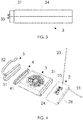
- the device according to the present patent application comprises a control and power supply module (2), functionally connected to at least one fan module (3) and to at least one hanging element (5) in order for it to be hung below a radiator.
- at least one of the longitudinal ends of the individual modules of the device includes connection means suitable for engaging the corresponding connection means of the adjacent modules, to make it possible to connect a plurality of fan modules (3) to one control and power supply module (2).
- the modular device here described is supplemented by at least one end module (4), which in turn includes connection means suitable for engaging the corresponding connection means of an adjacent module.
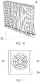
- the fan module (3) comprises a box-like body (34) whose horizontal faces are perforated, so as to allow the air driven by a vertical axis fan (3) to flow.
- the control and power supply module (2) usually receives power from the mains, but it might even receive power from a battery or, in any case, it might accommodate a battery internally thereto, to be used whenever the mains voltage fails. Also, the control and power supply module (2) comprises a sensor which takes the temperature of the surface of the radiator and keeps ventilation on only while the radiator is in operation.
- the temperature sensor is usually external to the control and power supply module (2) and comprises fixing means, for instance magnetic fixing means, for fixing it to the radiator.
- the control and power supply module (2) might comprise a user interface which might be used to set the operating parameters of the device.
- each longitudinal end of the fan module (3) includes a respective male or female connection means, in order for it to be possibly associated with the corresponding female or male connection means present in the corresponding longitudinal end of an adjacent module.
- the female connection means (32) consists of a perimetric ridge which longitudinally rises along the edge of either face of every fan module (3), whereas its corresponding connection means (31) consists of a ridge which longitudinally rises internally to the edge of the end face opposite to that of the female connection means (32); the outer side surface of the ridge of the male connection means (31) is suitable for engaging the inner side surface of its corresponding ridge of the female connection means (32).
- Each of the longitudinal ends of the fan modules (3) comprises a respective input electrical connector (35) and a respective output electrical connector (36), each of which is suitable for reciprocally engaging its corresponding electrical connector of an adjacent module.
- the output electrical connector of the fan module (3) associated with the end module (4) remains free.
- said input and output electrical connectors face each of said longitudinal ends of said modules respectively, in a symmetrical position with respect to the median plane of the ends themselves.
- the device (1) can be hung below a radiator by way of one or several hanging elements (5), each of which comprises an upper hook (52) and a lower closed ring (51); the fan modules (3) are accommodated internally to the latter.
- the installation of the device (1) on a radiator is particularly comfortable and stable if the upper hook (52) is at least partially elastic; the upper hook (52) is usually anchored above the lower manifold of the radiator, which connects different radiating elements to each other.
- a different embodiment comprises an open hanging element (50) with a ring that is open below so as to embrace the fan modules (3) at the transversal ends only.
- the modular device (1) comprises at least one bulkhead (6), which develops vertically and is provided below with coupling means for coupling with the coupling means of at least one fan module (3).
- the device comprises one bulkhead (6) for every fan module (3), however numerous variants are possible, for instance one wherein bulkheads develop longitudinally over two or several fan modules (3).
- the lower edge of the bulkhead (6) comprises a tooth (61) which is suitable for engaging a preferably longitudinal groove (37), cut on the upper face of the box-like body (34) of the fan module (3); this groove might be a through groove one.
- the bulkheads are made from a plastic material; variant are possible, for instance they might be made from a metal sheet.
Landscapes
- Engineering & Computer Science (AREA)
- Physics & Mathematics (AREA)
- Thermal Sciences (AREA)
- Mechanical Engineering (AREA)
- General Engineering & Computer Science (AREA)
- Chemical & Material Sciences (AREA)
- Combustion & Propulsion (AREA)
- Cooling Or The Like Of Electrical Apparatus (AREA)
- Structures Of Non-Positive Displacement Pumps (AREA)
Applications Claiming Priority (1)
| Application Number | Priority Date | Filing Date | Title |
|---|---|---|---|
| IT201700144897 | 2017-12-15 |
Publications (2)
| Publication Number | Publication Date |
|---|---|
| EP3499136A1 true EP3499136A1 (de) | 2019-06-19 |
| EP3499136B1 EP3499136B1 (de) | 2020-06-24 |
Family
ID=61868682
Family Applications (1)
| Application Number | Title | Priority Date | Filing Date |
|---|---|---|---|
| EP18202241.8A Active EP3499136B1 (de) | 2017-12-15 | 2018-10-24 | Modulare vorrichtung für radiatoren |
Country Status (1)
| Country | Link |
|---|---|
| EP (1) | EP3499136B1 (de) |
Citations (9)
| Publication number | Priority date | Publication date | Assignee | Title |
|---|---|---|---|---|
| ES2073340A2 (es) * | 1993-02-19 | 1995-08-01 | Avila Jesus Quintanilla | Convector termostatado de aire forzado por electroventiladores para radiadores de calefaccion domestica. |
| WO2007067082A1 (fr) * | 2005-12-05 | 2007-06-14 | Mircea Manolescu | Dispositif d'augmentation de la puissance des radiateurs classiques |
| SE0701765L (sv) | 2007-07-23 | 2009-01-24 | Herbert Lindgren | Moduluppbyggd lufttransportenhet |
| DE202008013447U1 (de) | 2008-10-09 | 2009-03-05 | A-Cosmetic Limited | Zirkulationssatz für Heizkörper - nachrüstbar |
| WO2009133543A1 (en) * | 2008-05-01 | 2009-11-05 | K.A. Enviro Manufacturing Limited | Convection space heater |
| US7789129B1 (en) * | 2008-06-11 | 2010-09-07 | Barden John A | User-operated air-flow enhancing device for improving heat distribution from an existing baseboard radiator and associated method |
| DE202010011282U1 (de) | 2010-08-11 | 2010-10-28 | Michalzik, Claudia | Zusatzgerät für Heizkörper |
| EP3124879A1 (de) | 2015-07-28 | 2017-02-01 | Gary Stanton Webster | Kühlerlüftereinheit |
| NL2015238B1 (nl) * | 2015-07-29 | 2017-02-20 | Climate Booster B V | Verwarmingssysteem, warmte-eenheid en werkwijze. |
-
2018
- 2018-10-24 EP EP18202241.8A patent/EP3499136B1/de active Active
Patent Citations (11)
| Publication number | Priority date | Publication date | Assignee | Title |
|---|---|---|---|---|
| ES2073340A2 (es) * | 1993-02-19 | 1995-08-01 | Avila Jesus Quintanilla | Convector termostatado de aire forzado por electroventiladores para radiadores de calefaccion domestica. |
| ES2073340B1 (es) | 1993-02-19 | 1998-02-16 | Quintanilla Avila Jesus | Convector termostatado de aire forzado por electroventiladores para radiadores de calefaccion domestica. |
| WO2007067082A1 (fr) * | 2005-12-05 | 2007-06-14 | Mircea Manolescu | Dispositif d'augmentation de la puissance des radiateurs classiques |
| SE0701765L (sv) | 2007-07-23 | 2009-01-24 | Herbert Lindgren | Moduluppbyggd lufttransportenhet |
| WO2009014478A1 (en) * | 2007-07-23 | 2009-01-29 | Herbert Lindgren | Flexible mounting and installation system with components specially adapted for the transport of air |
| WO2009133543A1 (en) * | 2008-05-01 | 2009-11-05 | K.A. Enviro Manufacturing Limited | Convection space heater |
| US7789129B1 (en) * | 2008-06-11 | 2010-09-07 | Barden John A | User-operated air-flow enhancing device for improving heat distribution from an existing baseboard radiator and associated method |
| DE202008013447U1 (de) | 2008-10-09 | 2009-03-05 | A-Cosmetic Limited | Zirkulationssatz für Heizkörper - nachrüstbar |
| DE202010011282U1 (de) | 2010-08-11 | 2010-10-28 | Michalzik, Claudia | Zusatzgerät für Heizkörper |
| EP3124879A1 (de) | 2015-07-28 | 2017-02-01 | Gary Stanton Webster | Kühlerlüftereinheit |
| NL2015238B1 (nl) * | 2015-07-29 | 2017-02-20 | Climate Booster B V | Verwarmingssysteem, warmte-eenheid en werkwijze. |
Also Published As
| Publication number | Publication date |
|---|---|
| EP3499136B1 (de) | 2020-06-24 |
Similar Documents
| Publication | Publication Date | Title |
|---|---|---|
| US8347950B2 (en) | Modular room heat exchange system with light unit | |
| US20090140065A1 (en) | Hvac controller with save a wire terminal | |
| CN207303426U (zh) | 用于hvac壁可安装连接器的跳接开关 | |
| CN105318400A (zh) | 一种模块化的地暖系统 | |
| CN203985427U (zh) | 一种具有温度调节器的宠物笼 | |
| KR101191538B1 (ko) | 태양 온수 난방 시스템 | |
| EP3499136B1 (de) | Modulare vorrichtung für radiatoren | |
| US9976774B1 (en) | Heating system, kit and method of using | |
| CN201964523U (zh) | 一种室内供暖装置 | |
| CN206905086U (zh) | 一种蓄热电暖器 | |
| CN105318399A (zh) | 一种模块化的墙暖系统 | |
| CN212515317U (zh) | 一种用于智能相机的自动加热装置 | |
| CN210402118U (zh) | 智能调温装置 | |
| CN209944498U (zh) | 用于连接燃气采暖热水炉和热泵的连接装置及具有该装置的供暖系统 | |
| EP4392719B1 (de) | Lüfteranordnung für radiator | |
| CN215523862U (zh) | 冷藏设备 | |
| CN213880704U (zh) | 低温环境下电控柜内电子元件保护性加热装置 | |
| CN208687834U (zh) | 具有独立加湿功能的电暖器 | |
| EA016524B1 (ru) | Система обогрева | |
| CN222147935U (zh) | 一种室内智能恒温器 | |
| US11137147B2 (en) | Variably heatable radiator | |
| CN111336582A (zh) | 控制面板 | |
| US11243011B2 (en) | Heat emitting radiator | |
| CN103868234A (zh) | 电空气加热器 | |
| CN218064998U (zh) | 一种无风扇电陶炉 |
Legal Events
| Date | Code | Title | Description |
|---|---|---|---|
| PUAI | Public reference made under article 153(3) epc to a published international application that has entered the european phase |
Free format text: ORIGINAL CODE: 0009012 |
|
| STAA | Information on the status of an ep patent application or granted ep patent |
Free format text: STATUS: THE APPLICATION HAS BEEN PUBLISHED |
|
| AK | Designated contracting states |
Kind code of ref document: A1 Designated state(s): AL AT BE BG CH CY CZ DE DK EE ES FI FR GB GR HR HU IE IS IT LI LT LU LV MC MK MT NL NO PL PT RO RS SE SI SK SM TR |
|
| AX | Request for extension of the european patent |
Extension state: BA ME |
|
| STAA | Information on the status of an ep patent application or granted ep patent |
Free format text: STATUS: REQUEST FOR EXAMINATION WAS MADE |
|
| 17P | Request for examination filed |
Effective date: 20190913 |
|
| RBV | Designated contracting states (corrected) |
Designated state(s): AL AT BE BG CH CY CZ DE DK EE ES FI FR GB GR HR HU IE IS IT LI LT LU LV MC MK MT NL NO PL PT RO RS SE SI SK SM TR |
|
| GRAP | Despatch of communication of intention to grant a patent |
Free format text: ORIGINAL CODE: EPIDOSNIGR1 |
|
| STAA | Information on the status of an ep patent application or granted ep patent |
Free format text: STATUS: GRANT OF PATENT IS INTENDED |
|
| RIC1 | Information provided on ipc code assigned before grant |
Ipc: F28D 1/053 20060101ALI20191205BHEP Ipc: F28D 21/00 20060101ALI20191205BHEP Ipc: F24F 1/00 20190101ALI20191205BHEP Ipc: F28D 1/02 20060101ALI20191205BHEP Ipc: F24D 19/00 20060101AFI20191205BHEP Ipc: F24F 1/0033 20190101ALI20191205BHEP Ipc: F28D 1/03 20060101ALI20191205BHEP |
|
| INTG | Intention to grant announced |
Effective date: 20200103 |
|
| GRAS | Grant fee paid |
Free format text: ORIGINAL CODE: EPIDOSNIGR3 |
|
| GRAA | (expected) grant |
Free format text: ORIGINAL CODE: 0009210 |
|
| STAA | Information on the status of an ep patent application or granted ep patent |
Free format text: STATUS: THE PATENT HAS BEEN GRANTED |
|
| AK | Designated contracting states |
Kind code of ref document: B1 Designated state(s): AL AT BE BG CH CY CZ DE DK EE ES FI FR GB GR HR HU IE IS IT LI LT LU LV MC MK MT NL NO PL PT RO RS SE SI SK SM TR |
|
| REG | Reference to a national code |
Ref country code: GB Ref legal event code: FG4D |
|
| REG | Reference to a national code |
Ref country code: CH Ref legal event code: EP |
|
| REG | Reference to a national code |
Ref country code: DE Ref legal event code: R096 Ref document number: 602018005547 Country of ref document: DE |
|
| REG | Reference to a national code |
Ref country code: AT Ref legal event code: REF Ref document number: 1284275 Country of ref document: AT Kind code of ref document: T Effective date: 20200715 |
|
| REG | Reference to a national code |
Ref country code: IE Ref legal event code: FG4D |
|
| PG25 | Lapsed in a contracting state [announced via postgrant information from national office to epo] |
Ref country code: FI Free format text: LAPSE BECAUSE OF FAILURE TO SUBMIT A TRANSLATION OF THE DESCRIPTION OR TO PAY THE FEE WITHIN THE PRESCRIBED TIME-LIMIT Effective date: 20200624 Ref country code: GR Free format text: LAPSE BECAUSE OF FAILURE TO SUBMIT A TRANSLATION OF THE DESCRIPTION OR TO PAY THE FEE WITHIN THE PRESCRIBED TIME-LIMIT Effective date: 20200925 Ref country code: NO Free format text: LAPSE BECAUSE OF FAILURE TO SUBMIT A TRANSLATION OF THE DESCRIPTION OR TO PAY THE FEE WITHIN THE PRESCRIBED TIME-LIMIT Effective date: 20200924 Ref country code: SE Free format text: LAPSE BECAUSE OF FAILURE TO SUBMIT A TRANSLATION OF THE DESCRIPTION OR TO PAY THE FEE WITHIN THE PRESCRIBED TIME-LIMIT Effective date: 20200624 Ref country code: LT Free format text: LAPSE BECAUSE OF FAILURE TO SUBMIT A TRANSLATION OF THE DESCRIPTION OR TO PAY THE FEE WITHIN THE PRESCRIBED TIME-LIMIT Effective date: 20200624 |
|
| REG | Reference to a national code |
Ref country code: LT Ref legal event code: MG4D |
|
| PG25 | Lapsed in a contracting state [announced via postgrant information from national office to epo] |
Ref country code: BG Free format text: LAPSE BECAUSE OF FAILURE TO SUBMIT A TRANSLATION OF THE DESCRIPTION OR TO PAY THE FEE WITHIN THE PRESCRIBED TIME-LIMIT Effective date: 20200924 Ref country code: HR Free format text: LAPSE BECAUSE OF FAILURE TO SUBMIT A TRANSLATION OF THE DESCRIPTION OR TO PAY THE FEE WITHIN THE PRESCRIBED TIME-LIMIT Effective date: 20200624 Ref country code: LV Free format text: LAPSE BECAUSE OF FAILURE TO SUBMIT A TRANSLATION OF THE DESCRIPTION OR TO PAY THE FEE WITHIN THE PRESCRIBED TIME-LIMIT Effective date: 20200624 Ref country code: RS Free format text: LAPSE BECAUSE OF FAILURE TO SUBMIT A TRANSLATION OF THE DESCRIPTION OR TO PAY THE FEE WITHIN THE PRESCRIBED TIME-LIMIT Effective date: 20200624 |
|
| REG | Reference to a national code |
Ref country code: NL Ref legal event code: MP Effective date: 20200624 |
|
| REG | Reference to a national code |
Ref country code: AT Ref legal event code: MK05 Ref document number: 1284275 Country of ref document: AT Kind code of ref document: T Effective date: 20200624 |
|
| PG25 | Lapsed in a contracting state [announced via postgrant information from national office to epo] |
Ref country code: NL Free format text: LAPSE BECAUSE OF FAILURE TO SUBMIT A TRANSLATION OF THE DESCRIPTION OR TO PAY THE FEE WITHIN THE PRESCRIBED TIME-LIMIT Effective date: 20200624 Ref country code: AL Free format text: LAPSE BECAUSE OF FAILURE TO SUBMIT A TRANSLATION OF THE DESCRIPTION OR TO PAY THE FEE WITHIN THE PRESCRIBED TIME-LIMIT Effective date: 20200624 |
|
| PG25 | Lapsed in a contracting state [announced via postgrant information from national office to epo] |
Ref country code: AT Free format text: LAPSE BECAUSE OF FAILURE TO SUBMIT A TRANSLATION OF THE DESCRIPTION OR TO PAY THE FEE WITHIN THE PRESCRIBED TIME-LIMIT Effective date: 20200624 Ref country code: EE Free format text: LAPSE BECAUSE OF FAILURE TO SUBMIT A TRANSLATION OF THE DESCRIPTION OR TO PAY THE FEE WITHIN THE PRESCRIBED TIME-LIMIT Effective date: 20200624 Ref country code: SM Free format text: LAPSE BECAUSE OF FAILURE TO SUBMIT A TRANSLATION OF THE DESCRIPTION OR TO PAY THE FEE WITHIN THE PRESCRIBED TIME-LIMIT Effective date: 20200624 Ref country code: PT Free format text: LAPSE BECAUSE OF FAILURE TO SUBMIT A TRANSLATION OF THE DESCRIPTION OR TO PAY THE FEE WITHIN THE PRESCRIBED TIME-LIMIT Effective date: 20201026 Ref country code: CZ Free format text: LAPSE BECAUSE OF FAILURE TO SUBMIT A TRANSLATION OF THE DESCRIPTION OR TO PAY THE FEE WITHIN THE PRESCRIBED TIME-LIMIT Effective date: 20200624 Ref country code: IT Free format text: LAPSE BECAUSE OF FAILURE TO SUBMIT A TRANSLATION OF THE DESCRIPTION OR TO PAY THE FEE WITHIN THE PRESCRIBED TIME-LIMIT Effective date: 20200624 Ref country code: ES Free format text: LAPSE BECAUSE OF FAILURE TO SUBMIT A TRANSLATION OF THE DESCRIPTION OR TO PAY THE FEE WITHIN THE PRESCRIBED TIME-LIMIT Effective date: 20200624 Ref country code: RO Free format text: LAPSE BECAUSE OF FAILURE TO SUBMIT A TRANSLATION OF THE DESCRIPTION OR TO PAY THE FEE WITHIN THE PRESCRIBED TIME-LIMIT Effective date: 20200624 |
|
| PG25 | Lapsed in a contracting state [announced via postgrant information from national office to epo] |
Ref country code: PL Free format text: LAPSE BECAUSE OF FAILURE TO SUBMIT A TRANSLATION OF THE DESCRIPTION OR TO PAY THE FEE WITHIN THE PRESCRIBED TIME-LIMIT Effective date: 20200624 Ref country code: SK Free format text: LAPSE BECAUSE OF FAILURE TO SUBMIT A TRANSLATION OF THE DESCRIPTION OR TO PAY THE FEE WITHIN THE PRESCRIBED TIME-LIMIT Effective date: 20200624 Ref country code: IS Free format text: LAPSE BECAUSE OF FAILURE TO SUBMIT A TRANSLATION OF THE DESCRIPTION OR TO PAY THE FEE WITHIN THE PRESCRIBED TIME-LIMIT Effective date: 20201024 |
|
| REG | Reference to a national code |
Ref country code: DE Ref legal event code: R097 Ref document number: 602018005547 Country of ref document: DE |
|
| PG25 | Lapsed in a contracting state [announced via postgrant information from national office to epo] |
Ref country code: DK Free format text: LAPSE BECAUSE OF FAILURE TO SUBMIT A TRANSLATION OF THE DESCRIPTION OR TO PAY THE FEE WITHIN THE PRESCRIBED TIME-LIMIT Effective date: 20200624 |
|
| PLBE | No opposition filed within time limit |
Free format text: ORIGINAL CODE: 0009261 |
|
| STAA | Information on the status of an ep patent application or granted ep patent |
Free format text: STATUS: NO OPPOSITION FILED WITHIN TIME LIMIT |
|
| 26N | No opposition filed |
Effective date: 20210325 |
|
| PG25 | Lapsed in a contracting state [announced via postgrant information from national office to epo] |
Ref country code: MC Free format text: LAPSE BECAUSE OF FAILURE TO SUBMIT A TRANSLATION OF THE DESCRIPTION OR TO PAY THE FEE WITHIN THE PRESCRIBED TIME-LIMIT Effective date: 20200624 Ref country code: LU Free format text: LAPSE BECAUSE OF NON-PAYMENT OF DUE FEES Effective date: 20201024 |
|
| REG | Reference to a national code |
Ref country code: BE Ref legal event code: MM Effective date: 20201031 |
|
| PG25 | Lapsed in a contracting state [announced via postgrant information from national office to epo] |
Ref country code: SI Free format text: LAPSE BECAUSE OF FAILURE TO SUBMIT A TRANSLATION OF THE DESCRIPTION OR TO PAY THE FEE WITHIN THE PRESCRIBED TIME-LIMIT Effective date: 20200624 Ref country code: BE Free format text: LAPSE BECAUSE OF NON-PAYMENT OF DUE FEES Effective date: 20201031 |
|
| PG25 | Lapsed in a contracting state [announced via postgrant information from national office to epo] |
Ref country code: IE Free format text: LAPSE BECAUSE OF NON-PAYMENT OF DUE FEES Effective date: 20201024 |
|
| PG25 | Lapsed in a contracting state [announced via postgrant information from national office to epo] |
Ref country code: TR Free format text: LAPSE BECAUSE OF FAILURE TO SUBMIT A TRANSLATION OF THE DESCRIPTION OR TO PAY THE FEE WITHIN THE PRESCRIBED TIME-LIMIT Effective date: 20200624 Ref country code: MT Free format text: LAPSE BECAUSE OF FAILURE TO SUBMIT A TRANSLATION OF THE DESCRIPTION OR TO PAY THE FEE WITHIN THE PRESCRIBED TIME-LIMIT Effective date: 20200624 Ref country code: CY Free format text: LAPSE BECAUSE OF FAILURE TO SUBMIT A TRANSLATION OF THE DESCRIPTION OR TO PAY THE FEE WITHIN THE PRESCRIBED TIME-LIMIT Effective date: 20200624 |
|
| PG25 | Lapsed in a contracting state [announced via postgrant information from national office to epo] |
Ref country code: MK Free format text: LAPSE BECAUSE OF FAILURE TO SUBMIT A TRANSLATION OF THE DESCRIPTION OR TO PAY THE FEE WITHIN THE PRESCRIBED TIME-LIMIT Effective date: 20200624 |
|
| GBPC | Gb: european patent ceased through non-payment of renewal fee |
Effective date: 20221024 |
|
| PG25 | Lapsed in a contracting state [announced via postgrant information from national office to epo] |
Ref country code: GB Free format text: LAPSE BECAUSE OF NON-PAYMENT OF DUE FEES Effective date: 20221024 |
|
| PGFP | Annual fee paid to national office [announced via postgrant information from national office to epo] |
Ref country code: FR Payment date: 20250925 Year of fee payment: 8 |
|
| REG | Reference to a national code |
Ref country code: CH Ref legal event code: U11 Free format text: ST27 STATUS EVENT CODE: U-0-0-U10-U11 (AS PROVIDED BY THE NATIONAL OFFICE) Effective date: 20251101 |
|
| PGFP | Annual fee paid to national office [announced via postgrant information from national office to epo] |
Ref country code: DE Payment date: 20250926 Year of fee payment: 8 |
|
| PGFP | Annual fee paid to national office [announced via postgrant information from national office to epo] |
Ref country code: CH Payment date: 20251101 Year of fee payment: 8 |