EP3499098A1 - Sliding component - Google Patents
Sliding component Download PDFInfo
- Publication number
- EP3499098A1 EP3499098A1 EP17841422.3A EP17841422A EP3499098A1 EP 3499098 A1 EP3499098 A1 EP 3499098A1 EP 17841422 A EP17841422 A EP 17841422A EP 3499098 A1 EP3499098 A1 EP 3499098A1
- Authority
- EP
- European Patent Office
- Prior art keywords
- sliding
- seal ring
- substrate
- sliding face
- sheet member
- Prior art date
- Legal status (The legal status is an assumption and is not a legal conclusion. Google has not performed a legal analysis and makes no representation as to the accuracy of the status listed.)
- Granted
Links
Images



Classifications
-
- F—MECHANICAL ENGINEERING; LIGHTING; HEATING; WEAPONS; BLASTING
- F16—ENGINEERING ELEMENTS AND UNITS; GENERAL MEASURES FOR PRODUCING AND MAINTAINING EFFECTIVE FUNCTIONING OF MACHINES OR INSTALLATIONS; THERMAL INSULATION IN GENERAL
- F16J—PISTONS; CYLINDERS; SEALINGS
- F16J15/00—Sealings
- F16J15/16—Sealings between relatively-moving surfaces
- F16J15/34—Sealings between relatively-moving surfaces with slip-ring pressed against a more or less radial face on one member
- F16J15/3496—Sealings between relatively-moving surfaces with slip-ring pressed against a more or less radial face on one member use of special materials
-
- F—MECHANICAL ENGINEERING; LIGHTING; HEATING; WEAPONS; BLASTING
- F16—ENGINEERING ELEMENTS AND UNITS; GENERAL MEASURES FOR PRODUCING AND MAINTAINING EFFECTIVE FUNCTIONING OF MACHINES OR INSTALLATIONS; THERMAL INSULATION IN GENERAL
- F16C—SHAFTS; FLEXIBLE SHAFTS; ELEMENTS OR CRANKSHAFT MECHANISMS; ROTARY BODIES OTHER THAN GEARING ELEMENTS; BEARINGS
- F16C17/00—Sliding-contact bearings for exclusively rotary movement
- F16C17/04—Sliding-contact bearings for exclusively rotary movement for axial load only
-
- F—MECHANICAL ENGINEERING; LIGHTING; HEATING; WEAPONS; BLASTING
- F16—ENGINEERING ELEMENTS AND UNITS; GENERAL MEASURES FOR PRODUCING AND MAINTAINING EFFECTIVE FUNCTIONING OF MACHINES OR INSTALLATIONS; THERMAL INSULATION IN GENERAL
- F16C—SHAFTS; FLEXIBLE SHAFTS; ELEMENTS OR CRANKSHAFT MECHANISMS; ROTARY BODIES OTHER THAN GEARING ELEMENTS; BEARINGS
- F16C17/00—Sliding-contact bearings for exclusively rotary movement
- F16C17/04—Sliding-contact bearings for exclusively rotary movement for axial load only
- F16C17/045—Sliding-contact bearings for exclusively rotary movement for axial load only with grooves in the bearing surface to generate hydrodynamic pressure, e.g. spiral groove thrust bearings
-
- F—MECHANICAL ENGINEERING; LIGHTING; HEATING; WEAPONS; BLASTING
- F16—ENGINEERING ELEMENTS AND UNITS; GENERAL MEASURES FOR PRODUCING AND MAINTAINING EFFECTIVE FUNCTIONING OF MACHINES OR INSTALLATIONS; THERMAL INSULATION IN GENERAL
- F16C—SHAFTS; FLEXIBLE SHAFTS; ELEMENTS OR CRANKSHAFT MECHANISMS; ROTARY BODIES OTHER THAN GEARING ELEMENTS; BEARINGS
- F16C33/00—Parts of bearings; Special methods for making bearings or parts thereof
- F16C33/02—Parts of sliding-contact bearings
- F16C33/04—Brasses; Bushes; Linings
- F16C33/06—Sliding surface mainly made of metal
- F16C33/10—Construction relative to lubrication
- F16C33/1025—Construction relative to lubrication with liquid, e.g. oil, as lubricant
- F16C33/106—Details of distribution or circulation inside the bearings, e.g. details of the bearing surfaces to affect flow or pressure of the liquid
- F16C33/1065—Grooves on a bearing surface for distributing or collecting the liquid
-
- F—MECHANICAL ENGINEERING; LIGHTING; HEATING; WEAPONS; BLASTING
- F16—ENGINEERING ELEMENTS AND UNITS; GENERAL MEASURES FOR PRODUCING AND MAINTAINING EFFECTIVE FUNCTIONING OF MACHINES OR INSTALLATIONS; THERMAL INSULATION IN GENERAL
- F16C—SHAFTS; FLEXIBLE SHAFTS; ELEMENTS OR CRANKSHAFT MECHANISMS; ROTARY BODIES OTHER THAN GEARING ELEMENTS; BEARINGS
- F16C33/00—Parts of bearings; Special methods for making bearings or parts thereof
- F16C33/02—Parts of sliding-contact bearings
- F16C33/04—Brasses; Bushes; Linings
- F16C33/06—Sliding surface mainly made of metal
- F16C33/10—Construction relative to lubrication
- F16C33/1025—Construction relative to lubrication with liquid, e.g. oil, as lubricant
- F16C33/106—Details of distribution or circulation inside the bearings, e.g. details of the bearing surfaces to affect flow or pressure of the liquid
- F16C33/107—Grooves for generating pressure
-
- F—MECHANICAL ENGINEERING; LIGHTING; HEATING; WEAPONS; BLASTING
- F16—ENGINEERING ELEMENTS AND UNITS; GENERAL MEASURES FOR PRODUCING AND MAINTAINING EFFECTIVE FUNCTIONING OF MACHINES OR INSTALLATIONS; THERMAL INSULATION IN GENERAL
- F16C—SHAFTS; FLEXIBLE SHAFTS; ELEMENTS OR CRANKSHAFT MECHANISMS; ROTARY BODIES OTHER THAN GEARING ELEMENTS; BEARINGS
- F16C33/00—Parts of bearings; Special methods for making bearings or parts thereof
- F16C33/72—Sealings
- F16C33/74—Sealings of sliding-contact bearings
-
- F—MECHANICAL ENGINEERING; LIGHTING; HEATING; WEAPONS; BLASTING
- F16—ENGINEERING ELEMENTS AND UNITS; GENERAL MEASURES FOR PRODUCING AND MAINTAINING EFFECTIVE FUNCTIONING OF MACHINES OR INSTALLATIONS; THERMAL INSULATION IN GENERAL
- F16J—PISTONS; CYLINDERS; SEALINGS
- F16J15/00—Sealings
- F16J15/16—Sealings between relatively-moving surfaces
- F16J15/34—Sealings between relatively-moving surfaces with slip-ring pressed against a more or less radial face on one member
-
- F—MECHANICAL ENGINEERING; LIGHTING; HEATING; WEAPONS; BLASTING
- F16—ENGINEERING ELEMENTS AND UNITS; GENERAL MEASURES FOR PRODUCING AND MAINTAINING EFFECTIVE FUNCTIONING OF MACHINES OR INSTALLATIONS; THERMAL INSULATION IN GENERAL
- F16J—PISTONS; CYLINDERS; SEALINGS
- F16J15/00—Sealings
- F16J15/16—Sealings between relatively-moving surfaces
- F16J15/34—Sealings between relatively-moving surfaces with slip-ring pressed against a more or less radial face on one member
- F16J15/3404—Sealings between relatively-moving surfaces with slip-ring pressed against a more or less radial face on one member and characterised by parts or details relating to lubrication, cooling or venting of the seal
- F16J15/3408—Sealings between relatively-moving surfaces with slip-ring pressed against a more or less radial face on one member and characterised by parts or details relating to lubrication, cooling or venting of the seal at least one ring having an uneven slipping surface
- F16J15/3412—Sealings between relatively-moving surfaces with slip-ring pressed against a more or less radial face on one member and characterised by parts or details relating to lubrication, cooling or venting of the seal at least one ring having an uneven slipping surface with cavities
Definitions
- the present invention relates to sliding components suitable, for example, as mechanical seals, bearings, and other sliding units. More particularly, the present invention relates to sliding components such as seal rings or bearings that require a reduction of friction by interposing fluid between sliding faces, and prevention of leakage of the fluid from the sliding faces.
- a mechanical seal an example of a sliding component, is evaluated for its performance by the leakage rate, wear rate, and torque thereof.
- Conventional arts have optimized the sliding material and the sliding face roughness of mechanical seals, thereby enhancing the performance and achieving low leakage, long life, and low torque.
- due to growing awareness of environmental problems in recent years a further improvement in the performance of mechanical seals has been required.
- technical development beyond the limits of the conventional arts has been necessary.
- an additive in antifreeze e.g. a rust-inhibiting component can be concentrated on a sliding face, forming deposits, and thus degrading the function of the mechanical seal.
- the deposit formation is considered to be a phenomenon that occurs likewise in mechanical seals of apparatuses that handle chemicals or oils.
- DLC diamond-like carbon
- a sliding material having excellent tribological properties known is one including a hard carbon film with glassy carbon formed all over a sliding face of a sliding material, a micro-periodic structure formed by irradiating the surface of the hard carbon film with a ultrashort pulse laser, and a lubricating layer containing a solid lubricant formed to cover the micro-periodic structure (hereinafter, referred to as "Conventional Art 3.” See Patent Document 3, for example.).
- Conventional Art 1 has a problem with durability because the diamond-like carbon film is about 1 ⁇ m in thickness, and thus tends to peel off.
- Conventional Art 2 has problems that there is a limit to manufacturing size because a large-volume one cannot be made of glassy carbon, that a crack or deformation occurs because gas generated during carbonization does not easily escape from inside, and that manufacturing takes time because of the necessity of slowing down the release of gas generated from inside.
- Conventional Art 3 has a problem that an advanced manufacturing technique is required. For example, substrate selection is necessary, and application of high-density energy is required to prevent a substrate from being thermally and mechanically degraded.
- a sliding component is a sliding component that includes an annular stationary-side seal ring fixed to a stationary side and an annular rotating-side seal ring rotating with a rotating shaft, the stationary-side seal ring and the rotating-side seal ring having respective sliding faces opposite to each other, the sliding faces being relatively rotated, thereby sealing a high-pressure fluid present on one radial side of the sliding faces relatively rotationally sliding, in which at least one of the stationary-side seal ring and the rotating-side seal ring includes a substrate, an adhesion layer on a sliding face side of the substrate, and a glassy carbon sheet member stuck on the substrate via the adhesion layer.
- the presence of glassy carbon on the sliding face of the seal ring prevents concentration of a deposit formation-causing substance and formation of deposits on the sliding face.
- the sliding component improved in the sealing function of the sliding face can be provided.
- Glassy carbon which is a material excellent in wear resistance, can prevent wear on the sliding face sliding in a fluid lubrication state from reaching a deep portion, improving the wear resistance and foreign matter-resistant properties of the sliding component.
- the sheet member of sheet-shaped glassy carbon is stuck on the sliding face side of the substrate.
- This configuration can facilitate the escape of gas generated from inside to prevent occurrence of cracks, compared to the case where an entire seal ring is formed of glassy carbon as in Conventional Art 2. Further, the poor thermal conductivity of glassy carbon can be covered by the material of the substrate.
- the surface texture can be formed on the sheet member, and thus is easily formed.
- the sheet member of sheet-shaped glassy carbon is stuck on the sliding face side of the substrate.
- This configuration enables provision of a glassy carbon region on the sliding face without requiring an advanced technique, compared to the case where a glassy carbon modified region is formed on a sliding face of a sliding material as in Conventional Art 3.
- the material of the substrate is not limited to materials that allow formation of a glassy carbon modified region.
- the degree of freedom in material selection can be increased.
- a low-cost material can be selected to reduce material cost.
- a material with good thermal conductivity can be selected to provide a sliding component with high heat dispersion characteristics.
- the surface texture can be formed on the sheet member, and thus is easily formed.
- the substrate is formed of carbon, SiC, or cemented carbide.
- the sliding component can be produced with a commonly used material.
- the adhesion layer is formed of a thermosetting resin.
- the glassy carbon sheet member can be securely integrated with the substrate.
- the sheet member in the sliding component in any one of the first to third aspects, has a sliding face provided with dimples.
- a sealed fluid can be held and positive pressure (dynamic pressure) can be generated at the sliding face, so that a fluid film between the sliding faces can be increased to improve lubrication performance.
- the dimples can be provided previously with a mold or by blanking when the sheet member is produced. Thus, the need to form the dimples after the sheet member is adhered to the substrate can be eliminated, and the dimples can be easily formed.
- the presence of the glassy carbon sheet member can prevent the deposition of precipitates on negative-pressure portions, and prevent the adhesion of deposits on a land.
- the sheet member in the sliding component in any one of the first to third aspects, has a sliding face provided with spiral grooves.
- positive pressure (dynamic pressure) can be generated at the sliding face, so that a fluid film between the sliding faces can be increased to improve lubrication performance.
- the spiral grooves can be provided previously with a mold or by blanking when the sheet member is produced. Thus, the need to form the spiral grooves after the sheet member is adhered to the substrate can be eliminated, and the spiral grooves can be easily formed.
- the presence of the glassy carbon sheet member can prevent the deposition of precipitates on negative-pressure portions, and prevent the adhesion of deposits on a land.
- the sheet member in the sliding component in any one of the first to third aspects, has a sliding face provided with at least one Rayleigh step mechanism.
- positive pressure (dynamic pressure) can be generated at the sliding face, so that a fluid film between the sliding faces can be increased to improve lubrication performance.
- the at least one Rayleigh step mechanism can be provided previously with a mold when the sheet member is produced. Thus, the need to form the at least one Rayleigh step mechanism after the sheet member is adhered to the substrate can be eliminated, and the at least one Rayleigh step mechanism can be easily formed.
- the presence of the glassy carbon sheet member can prevent the deposition of precipitates on negative-pressure portions, and prevent the adhesion of deposits on a land.
- the present invention achieves the following outstanding effects.
- Glassy carbon which is a material excellent in wear resistance, can prevent wear on the sliding face sliding in a fluid lubrication state from reaching a deep portion, improving the wear resistance and foreign matter-resistant properties of the sliding component.
- the sheet member of sheet-shaped glassy carbon is stuck on the sliding face side of the substrate.
- This configuration can facilitate the escape of gas generated from inside to prevent occurrence of cracks, compared to the case where an entire seal ring is formed of glassy carbon as in Conventional Art 2. Further, the poor thermal conductivity of glassy carbon can be covered by the material of the substrate.
- the surface texture can be formed on the sheet member, and thus is easily formed.
- the sheet member of sheet-shaped glassy carbon is stuck on the sliding face side of the substrate.
- This configuration enables provision of a glassy carbon region on the sliding face without requiring an advanced technique, compared to the case where a glassy carbon modified region is formed on a sliding face of a sliding material as in Conventional Art 3.
- the material of the substrate is not limited to materials that allow formation of a glassy carbon modified region.
- the degree of freedom in material selection can be increased.
- a low-cost material can be selected to reduce material cost.
- a material with good thermal conductivity can be selected to provide a sliding component with high heat dispersion characteristics.
- the surface texture can be formed on the sheet member, and thus is easily formed.
- the at least one Rayleigh step mechanism can be provided previously with a mold when the sheet member is produced. Thus, the need to form the at least one Rayleigh step mechanism after the sheet member is adhered to the substrate can be eliminated, and the at least one Rayleigh step mechanism can be easily formed.
- the presence of the glassy carbon sheet member can prevent the deposition of precipitates on negative-pressure portions, and prevent the adhesion of deposits on the land.
- This embodiment describes, as an example, a mechanical seal that is an example of the sliding component.
- the outer-peripheral side of sliding parts constituting the mechanical seal is described as the high-pressure fluid side (sealed fluid side), and the inner-peripheral side as the low-pressure fluid side (atmosphere side).
- the present invention is not limited to this, and is applicable to the case where the high-pressure fluid side and the low-pressure fluid side are reversed.
- FIG. 1 is a vertical cross-sectional view showing an example of the mechanical seal, which is an inside mechanical seal in the form of sealing a sealed fluid on the high-pressure fluid side that tends to leak from the outer periphery toward the inner periphery of a sliding face S (In the description, when it is meaningful to refer to each sliding face of a pair of sliding faces, the sliding faces are referred to as “sliding faces S,” and when only one of the sliding faces is referred to, the sliding face is referred to as a “sliding face S.”).
- the mechanical seal is provided with an annular rotating-side seal ring 3 that is one seal ring provided via a sleeve 2 and a cup gasket 8 at a rotating shaft 1 to drive a rotating member (not shown) on the high-pressure fluid side, in a state of being integrally rotatable with the rotating shaft 1, and an annular stationary-side seal ring 5 that is the other seal ring provided at a housing 4 via a sleeve 7 in non-rotating and axially movable states.
- a biasing member 6 axially biasing the stationary-side seal ring 5, the rotating-side seal ring 3 and the stationary-side seal ring 5 slide in close contact with each other at the sliding faces S mirror-finished by lapping or the like.
- the mechanical seal prevents, at respective sliding faces S of the rotating-side seal ring 3 and the stationary-side seal ring 5, the sealed fluid from flowing out from the high-pressure fluid side (outer-peripheral side) into the low-pressure fluid side (inner-peripheral side) of the two seal rings 3 and 5.
- the radial width of the sliding face S of the rotating-side seal ring 3 is set smaller than the radial width of the sliding face S of the stationary-side seal ring 5.
- the entire region of the sliding face S of the rotating-side seal ring 3 is brought into contact with the sliding face S of the stationary-side seal ring 5.
- the sliding faces of the two seal rings 3 and 5 slide relatively in a fluid lubrication state.
- the present invention is not limited to FIG. 1 .
- the radial width of the sliding face S of the rotating-side seal ring 3 may be set larger than the radial width of the sliding face S of the stationary-side seal ring 5.
- the rotating-side seal ring 3 includes a substrate 3a, an adhesion layer 3b on the sliding face side of the substrate 3a, and a glassy carbon sheet member 3c stuck on the substrate 3a via the adhesion layer 3b. This point will be described in detail later.
- the other seal ring, in this example, the stationary-side seal ring 5 is formed of a substrate in one body.
- a stationary-side seal ring may include an adhesion layer on the sliding face side of a substrate, and a glassy carbon sheet member stuck on the substrate via the adhesion layer, and a rotating-side seal ring may be formed of a substrate in one body.
- the sealed fluid is a fluid such as antifreeze to which a rust inhibitor is added.
- the material of the substrates of the rotating-side seal ring 3 and the stationary-side seal ring 5 is typically selected from silicon carbide (SiC) excellent in wear resistance, carbon and cemented carbide excellent in self-lubricity, and the like.
- SiC silicon carbide
- both may be silicon carbide, or a combination of the rotating-side seal ring 3 being silicon carbide and the stationary-side seal ring 5 being carbon is possible.
- silicon carbide As a sliding material of mechanical seals or the like, silicon carbide, in particular, is known to be a suitable material with good heat dispersion characteristics and excellent wear resistance.
- silicon carbide As described above, there is a problem that because of the properties of a rust-inhibiting component contained in antifreeze, a deposit formation-causing substance concentrated and formed accumulates on a sliding face, causing the sliding face to lose smoothness, and thus leading to leakage.
- the present invention is characterized in that at least one seal ring of the rotating-side seal ring 3 and the stationary-side seal ring 5 includes a substrate, an adhesion layer on the sliding face side of the substrate, and a glassy carbon sheet member stuck on the substrate via the adhesion layer.
- Glassy carbon is a material made by carbonizing a thermosetting resin, not glass, and is characterized by not passing gas, passing electricity, being acid resistant, being wear resistant, and so on.
- thermosetting resin such as a phenol resin, a polyimide resin, an epoxy resin, or a furan resin is molded by injection molding, compression molding, or the like, and the resin molding is fired and carbonized in an inert gas atmosphere at one thousand some hundreds degrees Celsius. Firing causes elements other than carbon in the resin molding, that is, hydrogen, nitrogen, oxygen, and the like to chemically combine with carbon around them, forming cracked gas such as carbon dioxide, methane, ethane, and the like, and being released. Finally, only a carbon mesh skeleton is left, constituting glassy carbon.
- Glassy carbon also includes composite glassy carbon made by mixing a filler, a filling material, with a thermosetting resin, and firing the mixture.
- the composite glassy carbon can be further enhanced in properties such as lubricity by mixing a micro-sized or nano-sized filler.
- the rotating-side seal ring 3 includes the substrate 3a, the adhesion layer 3b on the sliding face side of the substrate 3a, and the glassy carbon sheet member 3c stuck on the substrate 3a via the adhesion layer 3b.
- the glassy carbon sheet member 3c is formed separately by working one made as a glassy carbon sheet member into the same shape as the planar shape of the sliding face side of the substrate 3a.
- the thickness of the glassy carbon sheet member 3c in the present invention is about 100 times larger than the thickness of the diamond-like carbon film that is about 1 ⁇ m in Conventional Art 1.
- the glassy carbon sheet member 3c is characterized by being resistant to peeling compared to the coating of the diamond-like carbon film.
- the adhesion layer 3b is made of a thermosetting resin, and is applied to the entire surface of the glassy carbon sheet member 3c.
- the substrate 3a is made of silicon carbide (SiC) or carbon, and is worked to a predetermined inner diameter d1, outer diameter d2, and thickness t.
- the adhesion layer 3b made of a thermosetting resin is applied to the sliding face side of the substrate 3a worked into a predetermined shape, and the glassy carbon sheet member 3c is attached to the top of the adhesion layer 3b, so that the glassy carbon sheet member 3c is stuck on the substrate 3a via the adhesion layer 3b.
- the adhesion layer 3b made of the thermosetting resin is heated to be cured. The curing of the thermosetting resin adhesion layer 3b causes the glassy carbon sheet member 3c to be stuck on the sliding face side of the substrate 3a and integrated with the substrate 3a.
- the adhesion layer 3b is heated to about 300°C to thermally cure the thermosetting resin.
- the adhesion layer 3b may be heated until the thermosetting resin is carbonized as needed.
- the sliding component in the first embodiment described above achieves the following outstanding effects.
- the material of the substrate 3a is not limited to materials that allow formation of a glassy carbon modified region.
- the degree of freedom in material selection can be increased.
- a low-cost material can be selected to reduce material cost.
- a material with good thermal conductivity can be selected to provide a sliding component with high heat dispersion characteristics.
- the surface texture can be formed on the sheet member 3c, and thus is easily formed.
- the sliding component according to the second embodiment is different from that of the first embodiment in that a surface texture is provided on a sliding face, but in the other basic configuration, is identical to that of the first embodiment, and will not be redundantly described.
- a rotating-side seal ring 3 includes a substrate 3a, an adhesion layer 3b on the sliding face side of the substrate 3a, and a glassy carbon sheet member 3c stuck on the substrate 3a via the adhesion layer 3b.
- a sliding face S of the sheet member 3c is provided with dimples 10.
- the dimples 10 are provided through the sheet member 3c, but are not limited to this.
- the dimples 10 may be provided to a depth shallower than the thickness of the sheet member 3c, for example.
- a plurality of circular dimples 10 is arranged circumferentially, independently of each other, and is separated from the high-pressure fluid side and the low-pressure fluid side by a land R (which means a portion on which no grooves such as dimples are formed).
- the shape of the dimples 10 may alternatively be oval, elliptic, or rectangular instead of being circular.
- the diameter and depth of the dimples 10 are determined in design depending on the specifications of the sliding component, that is, the diameter of the sliding face, sliding speed, the viscosity of a sealed fluid, and others.
- the diameter of the dimples 10 is properly in a range of 50 ⁇ m to 200 ⁇ m, and the depth in a range of 0.1 ⁇ m to 100 ⁇ m.
- the radial arrangement of the dimples 10 is not limited to two rows, and may be three or more rows.
- the circumferential pitch of the dimples 10 is determined in design as appropriate.
- the plurality of dimples 10 formed on the sliding face holds a sealed fluid entering as a hydrodynamic lubricating liquid film between the sliding face and the opposing sliding face.
- the individual dimples 10 can each be considered to constitute a Rayleigh step.
- a Rayleigh step is formed at a downstream surface 10a of each dimple 10 formed on the sliding face of the rotating-side seal ring 3.
- the downstream surface 10a is orthogonal to the rotational direction of the opposing sliding face shown by an arrow.
- the sliding face S of the stationary-side seal ring is flattened.
- Positive pressure generation mechanisms formed of the dimples 10 hold the sealed fluid, and generate positive pressure (dynamic pressure), thereby increasing a fluid film between the sliding faces S, and improving lubrication performance.
- the sliding component in the second embodiment described above achieves the following outstanding effects in addition to the effects of the first embodiment.
- the sliding component according to the third embodiment is different from that of the first embodiment in that a surface texture is provided on a sliding face, but in the other basic configuration, is identical to that of the first embodiment, and will not be redundantly described.
- a rotating-side seal ring 3 includes a substrate 3a, an adhesion layer 3b on the sliding face side of the substrate 3a, and a glassy carbon sheet member 3c stuck on the substrate 3a via the adhesion layer 3b.
- a sliding face S of the sheet member 3c is provided with spiral grooves 11.
- the sliding face S of the sheet member 3c is provided with a plurality of circumferentially spaced spiral grooves 11.
- the spiral grooves 11 are inclined from the outer-peripheral side toward the inner-peripheral side of the sliding face S in the rotational direction of the opposing sliding face, and communicate with the high-pressure fluid side at proximal ends 11a on the outer-peripheral side, and are separated from the low-pressure fluid side at distal ends 11b on the inner-peripheral side by a land R of the sliding face S, and blocked at groove outlets.
- each distal end 11b on the inner-peripheral side can be considered to constitute a Rayleigh step.
- the shape of the spiral grooves 11 is not limited to the shape shown in FIG. 4B , and may be, for example, a rectangular groove provided at an angle from the outer-peripheral side toward the inner-peripheral side of the sliding face S in the rotational direction of the opposing sliding face.
- the proximal ends 11a on the outer-peripheral side may alternatively be separated from the high-pressure fluid side by the land R without communicating with the high-pressure fluid side.
- the width and depth of the spiral grooves 11 are determined in design depending on the specifications of the sliding component, that is, the diameter of the sliding face, sliding speed, the viscosity of a sealed fluid, and others.
- Positive pressure generation mechanisms formed of the spiral grooves 11 introduce the sealed fluid into the spiral grooves 11 and generate positive pressure (dynamic pressure), thereby increasing a fluid film between the sliding faces S and thus improving lubrication performance.
- the sliding component in the third embodiment described above achieves the following outstanding effects in addition to the effects of the first embodiment.
- the sliding component according to the fourth embodiment is different from that of the first embodiment in that a surface texture is provided on a sliding face, but in the other basic configuration, is identical to that of the first embodiment, and will not be redundantly described.
- a rotating-side seal ring 3 includes a substrate 3a, an adhesion layer 3b on the sliding face side of the substrate 3a, and a glassy carbon sheet member 3c stuck on the substrate 3a via the adhesion layer 3b.
- a sliding face S of the sheet member 3c is provided with a plurality of Rayleigh step mechanisms 12.
- the sliding face S of the sheet member 3c is provided with the Rayleigh step mechanisms 12 each including a positive pressure generation groove 12a.
- Each positive pressure generation groove 12a communicates with a radial groove 13 deeper than the positive pressure generation groove 12a at an upstream inlet 12b, and is separated at portions other than the inlet 12b by a land R.
- each positive pressure generation groove 12a is 0.4 mm to 0.6 mm and the depth is some micrometers
- the width of each radial groove 13 (circumferential angle) is about 6° and the depth is some tens of micrometers.
- the plurality of Rayleigh step mechanisms 12 is provided in a circumferential direction of the sliding face S, which is not limiting. It is only necessary that at least one Rayleigh step mechanism 12 be provided.
- the Rayleigh step mechanisms 12 generate positive pressure (dynamic pressure), thereby increasing a fluid film between the sliding faces S and improving lubrication performance.
- the sliding component in the fourth embodiment described above achieves the following outstanding effects in addition to the effects of the first embodiment.
- the above embodiments have described the sliding component with an example where, of a pair of rotating and stationary seal rings in a mechanical seal device, the rotating seal ring includes a substrate, an adhesion layer on the sliding face side of the substrate, and a glassy carbon sheet member stuck on the substrate via the adhesion layer.
- the stationary seal ring may include a substrate, an adhesion layer on the sliding face side of the substrate, and a glassy carbon sheet member stuck on the substrate via the adhesion layer.
- the above embodiments have described the case where a high-pressure sealed fluid is present on the outer-peripheral side of a rotating seal ring and a stationary seal ring.
- the present invention is also applicable to the case where a high-pressure fluid is on the inner-peripheral side.
- the above embodiments have described the thickness of the glassy carbon sheet member 3c as being about 100 times larger than the thickness of the diamond-like carbon film that is about 1 ⁇ m. This only shows a general indicator.
- the thickness of the glassy carbon sheet member 3c is determined in design, depending on the specifications of the sliding component such as the outer diameter, the inner diameter, and sliding speed.
Landscapes
- Engineering & Computer Science (AREA)
- General Engineering & Computer Science (AREA)
- Mechanical Engineering (AREA)
- Chemical & Material Sciences (AREA)
- Oil, Petroleum & Natural Gas (AREA)
- Physics & Mathematics (AREA)
- Fluid Mechanics (AREA)
- Mechanical Sealing (AREA)
- Sliding-Contact Bearings (AREA)
- Sealing Of Bearings (AREA)
- Sealing Devices (AREA)
Abstract
Description
- The present invention relates to sliding components suitable, for example, as mechanical seals, bearings, and other sliding units. More particularly, the present invention relates to sliding components such as seal rings or bearings that require a reduction of friction by interposing fluid between sliding faces, and prevention of leakage of the fluid from the sliding faces.
- A mechanical seal, an example of a sliding component, is evaluated for its performance by the leakage rate, wear rate, and torque thereof. Conventional arts have optimized the sliding material and the sliding face roughness of mechanical seals, thereby enhancing the performance and achieving low leakage, long life, and low torque. However, due to growing awareness of environmental problems in recent years, a further improvement in the performance of mechanical seals has been required. Thus, technical development beyond the limits of the conventional arts has been necessary.
- It has been confirmed that in a mechanical seal used for cooling a water-cooled engine, for example, as time passes, an additive in antifreeze, e.g. a rust-inhibiting component can be concentrated on a sliding face, forming deposits, and thus degrading the function of the mechanical seal. The deposit formation is considered to be a phenomenon that occurs likewise in mechanical seals of apparatuses that handle chemicals or oils.
- In a mechanical seal using a surface texture, negative pressure can be generated in a sliding face, depending on its characteristics. An experiment has confirmed that a sealed fluid entering the sliding face due to the negative pressure can evaporate, causing a deposit formation-causing substance to be excessively precipitated and formed, forming deposits at an increasing rate, and thereby degrading the function of the mechanical seal.
- It is conceivable that a diamond-like carbon (abbreviated as DLC) film, for example, is noticed as a film of an adhesion-resistant material, and a sliding face of a sliding member is coated with diamond-like carbon, thereby preventing the buildup of deposits on a surface of a negative-pressure generation mechanism on which deposits tend to be precipitated and formed, as described in
Patent Documents 1 and 2 (hereinafter, referred to as "Conventional Art 1"). - It is likewise conceivable that from the viewpoint of preventing the buildup of deposits, a sliding part is made of glassy carbon (hereinafter, referred to as "Conventional
-
Art 2") . - As a sliding material having excellent tribological properties, known is one including a hard carbon film with glassy carbon formed all over a sliding face of a sliding material, a micro-periodic structure formed by irradiating the surface of the hard carbon film with a ultrashort pulse laser, and a lubricating layer containing a solid lubricant formed to cover the micro-periodic structure (hereinafter, referred to as "
Conventional Art 3." SeePatent Document 3, for example.). -
- Patent Document 1:
JP 2012-62534 A - Patent Document 2:
JP 5-296248 A - Patent Document 3:
JP 2007-162045 A - However,
Conventional Art 1 has a problem with durability because the diamond-like carbon film is about 1 µm in thickness, and thus tends to peel off. -
Conventional Art 2 has problems that there is a limit to manufacturing size because a large-volume one cannot be made of glassy carbon, that a crack or deformation occurs because gas generated during carbonization does not easily escape from inside, and that manufacturing takes time because of the necessity of slowing down the release of gas generated from inside. -
Conventional Art 3 has a problem that an advanced manufacturing technique is required. For example, substrate selection is necessary, and application of high-density energy is required to prevent a substrate from being thermally and mechanically degraded. - It is an object of the present invention to provide a sliding component that prevents a deposit formation-causing substance from forming deposits on a sliding face even when a liquid of antifreeze to which a rust inhibitor is added is sealed as in a mechanical seal suitable for cooling a water-cooled engine, for example, to improve the sealing function of the sliding face.
- In particular, it is an object of the present invention to provide a sliding component that prevents deposition of precipitates on negative-pressure portions and prevents adhesion of deposits on a land even when a deposit formation-causing substance is precipitated and formed from a sealed fluid entering a sliding face due to negative pressure at the sliding face, to improve the sealing function of the sliding face.
- It is also an object of the present invention to provide a sliding component improved in the wear resistance and foreign matter-resistant properties of a sliding face.
- To attain the above objects, a sliding component according to a first aspect of the present invention is a sliding component that includes an annular stationary-side seal ring fixed to a stationary side and an annular rotating-side seal ring rotating with a rotating shaft, the stationary-side seal ring and the rotating-side seal ring having respective sliding faces opposite to each other, the sliding faces being relatively rotated, thereby sealing a high-pressure fluid present on one radial side of the sliding faces relatively rotationally sliding, in which at least one of the stationary-side seal ring and the rotating-side seal ring includes a substrate, an adhesion layer on a sliding face side of the substrate, and a glassy carbon sheet member stuck on the substrate via the adhesion layer.
- According to this aspect, the presence of glassy carbon on the sliding face of the seal ring prevents concentration of a deposit formation-causing substance and formation of deposits on the sliding face. Thus, the sliding component improved in the sealing function of the sliding face can be provided.
- Glassy carbon, which is a material excellent in wear resistance, can prevent wear on the sliding face sliding in a fluid lubrication state from reaching a deep portion, improving the wear resistance and foreign matter-resistant properties of the sliding component.
- Separately from the substrate of the seal ring, the sheet member of sheet-shaped glassy carbon is stuck on the sliding face side of the substrate. This configuration can facilitate the escape of gas generated from inside to prevent occurrence of cracks, compared to the case where an entire seal ring is formed of glassy carbon as in
Conventional Art 2. Further, the poor thermal conductivity of glassy carbon can be covered by the material of the substrate. - Even a large seal ring that cannot be manufactured when an entire seal ring is formed of glassy carbon can be manufactured.
- Even when a surface texture is formed on the sliding face, the surface texture can be formed on the sheet member, and thus is easily formed.
- Separately from the substrate of the seal ring, the sheet member of sheet-shaped glassy carbon is stuck on the sliding face side of the substrate. This configuration enables provision of a glassy carbon region on the sliding face without requiring an advanced technique, compared to the case where a glassy carbon modified region is formed on a sliding face of a sliding material as in
Conventional Art 3. - The material of the substrate is not limited to materials that allow formation of a glassy carbon modified region. Thus, the degree of freedom in material selection can be increased. For example, a low-cost material can be selected to reduce material cost. Alternatively, for example, a material with good thermal conductivity can be selected to provide a sliding component with high heat dispersion characteristics.
- Even when a surface texture is formed on the sliding face, the surface texture can be formed on the sheet member, and thus is easily formed.
- According to a second aspect of the present invention, in the sliding component in the first aspect, the substrate is formed of carbon, SiC, or cemented carbide.
- According to this aspect, the sliding component can be produced with a commonly used material.
- According to a third aspect of the present invention, in the sliding component in the first or second aspect, the adhesion layer is formed of a thermosetting resin.
- According to this aspect, only by heating the adhesion layer, the glassy carbon sheet member can be securely integrated with the substrate.
- According to a fourth aspect of the present invention, in the sliding component in any one of the first to third aspects, the sheet member has a sliding face provided with dimples.
- According to this aspect, a sealed fluid can be held and positive pressure (dynamic pressure) can be generated at the sliding face, so that a fluid film between the sliding faces can be increased to improve lubrication performance.
- The dimples can be provided previously with a mold or by blanking when the sheet member is produced. Thus, the need to form the dimples after the sheet member is adhered to the substrate can be eliminated, and the dimples can be easily formed.
- Even when negative pressure is generated on the upstream side in the dimples, and a sealed fluid entering the sliding face evaporates, causing a deposit formation-causing substance to be precipitated and formed, the presence of the glassy carbon sheet member can prevent the deposition of precipitates on negative-pressure portions, and prevent the adhesion of deposits on a land.
- According to a fifth aspect of the present invention, in the sliding component in any one of the first to third aspects, the sheet member has a sliding face provided with spiral grooves.
- According to this aspect, positive pressure (dynamic pressure) can be generated at the sliding face, so that a fluid film between the sliding faces can be increased to improve lubrication performance.
- The spiral grooves can be provided previously with a mold or by blanking when the sheet member is produced. Thus, the need to form the spiral grooves after the sheet member is adhered to the substrate can be eliminated, and the spiral grooves can be easily formed.
- Even when negative pressure is generated on the upstream side in the spiral grooves, and a sealed fluid entering the sliding face evaporates, causing a deposit formation-causing substance to be precipitated and formed, the presence of the glassy carbon sheet member can prevent the deposition of precipitates on negative-pressure portions, and prevent the adhesion of deposits on a land.
- According to a sixth aspect of the present invention, in the sliding component in any one of the first to third aspects, the sheet member has a sliding face provided with at least one Rayleigh step mechanism.
- According to this aspect, positive pressure (dynamic pressure) can be generated at the sliding face, so that a fluid film between the sliding faces can be increased to improve lubrication performance.
- The at least one Rayleigh step mechanism can be provided previously with a mold when the sheet member is produced. Thus, the need to form the at least one Rayleigh step mechanism after the sheet member is adhered to the substrate can be eliminated, and the at least one Rayleigh step mechanism can be easily formed.
- Even when negative pressure is generated on the upstream side in the at least one Rayleigh step mechanism, and a deposit formation-causing substance is precipitated and formed from a sealed fluid entering the sliding face, the presence of the glassy carbon sheet member can prevent the deposition of precipitates on negative-pressure portions, and prevent the adhesion of deposits on a land.
- The present invention achieves the following outstanding effects.
- (1) At least one of the stationary-side seal ring and the rotating-side seal ring includes the substrate, the adhesion layer on the sliding face side of the substrate, and the glassy carbon sheet member stuck on the substrate via the adhesion layer, so that the presence of glassy carbon on the sliding face S of the seal ring prevents concentration of a deposit formation-causing substance and formation of deposits on the sliding face S. Thus, the sliding component improved in the sealing function of the sliding face can be provided.
- Glassy carbon, which is a material excellent in wear resistance, can prevent wear on the sliding face sliding in a fluid lubrication state from reaching a deep portion, improving the wear resistance and foreign matter-resistant properties of the sliding component.
- Separately from the substrate of the seal ring, the sheet member of sheet-shaped glassy carbon is stuck on the sliding face side of the substrate. This configuration can facilitate the escape of gas generated from inside to prevent occurrence of cracks, compared to the case where an entire seal ring is formed of glassy carbon as in
Conventional Art 2. Further, the poor thermal conductivity of glassy carbon can be covered by the material of the substrate. - Even a large seal ring that cannot be manufactured when an entire seal ring is formed of glassy carbon can be manufactured.
- Even when a surface texture is formed on the sliding face, the surface texture can be formed on the sheet member, and thus is easily formed.
- Separately from the substrate of the seal ring, the sheet member of sheet-shaped glassy carbon is stuck on the sliding face side of the substrate. This configuration enables provision of a glassy carbon region on the sliding face without requiring an advanced technique, compared to the case where a glassy carbon modified region is formed on a sliding face of a sliding material as in
Conventional Art 3. - The material of the substrate is not limited to materials that allow formation of a glassy carbon modified region. Thus, the degree of freedom in material selection can be increased. For example, a low-cost material can be selected to reduce material cost. Alternatively, for example, a material with good thermal conductivity can be selected to provide a sliding component with high heat dispersion characteristics.
- Even when a surface texture is formed on the sliding face, the surface texture can be formed on the sheet member, and thus is easily formed.
- (2) The substrate is formed of carbon, SiC, or cemented carbide, so that the sliding component can be produced with a commonly used material.
- (3) The adhesion layer is formed of a thermosetting resin, so that only by heating the adhesion layer, the glassy carbon sheet member can be securely integrated with the substrate.
- (4) The sheet member has the sliding face provided with the dimples, so that the sealed fluid can be held and positive pressure (dynamic pressure) can be generated at the sliding face. Thus, the fluid film between the sliding faces can be increased to improve lubrication performance.
The dimples can be provided previously with a mold or by blanking when the sheet member is produced. Thus, the need to form the dimples after the sheet member is adhered to the substrate can be eliminated, and the dimples can be easily formed.
Even when negative pressure is generated on the upstream side in the dimples, and a deposit formation-causing substance is precipitated and formed from the sealed fluid entering the sliding face, the presence of the glassy carbon sheet member can prevent the deposition of precipitates on negative-pressure portions, and prevent the adhesion of deposits on the land. - (5) The sheet member has the sliding face provided with the spiral grooves, so that positive pressure (dynamic pressure) can be generated at the sliding face, and the fluid film between the sliding faces can be increased to improve lubrication performance.
The spiral grooves can be provided previously with a mold or by blanking when the sheet member is produced. Thus, the need to form the spiral grooves after the sheet member is adhered to the substrate can be eliminated, and the spiral grooves can be easily formed.
Even when negative pressure is generated on the upstream side in the spiral grooves, and the sealed fluid entering the sliding face evaporates, causing a deposit formation-causing substance to be precipitated and formed, the presence of the glassy carbon sheet member can prevent the deposition of precipitates on negative-pressure portions, and prevent the adhesion of deposits on the land. - (6) The sheet member has the sliding face provided with the at least one Rayleigh step mechanism, so that positive pressure (dynamic pressure) can be generated at the sliding face, and the fluid film between the sliding faces can be increased to improve lubrication performance.
- The at least one Rayleigh step mechanism can be provided previously with a mold when the sheet member is produced. Thus, the need to form the at least one Rayleigh step mechanism after the sheet member is adhered to the substrate can be eliminated, and the at least one Rayleigh step mechanism can be easily formed.
- Even when negative pressure is generated on the upstream side in the at least one Rayleigh step mechanism, and the sealed fluid entering the sliding face evaporates, causing a deposit formation-causing substance to be precipitated and formed, the presence of the glassy carbon sheet member can prevent the deposition of precipitates on negative-pressure portions, and prevent the adhesion of deposits on the land.
-
-
FIG. 1 is a vertical cross-sectional view showing an example of a mechanical seal according to a first embodiment of the present invention. -
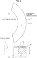
FIG. 2A is an enlarged cross-sectional view showing one sliding part of a sliding component according to the first embodiment of the present invention, provided such that a sliding face is located above. -
FIG. 2B is an enlarged plan view showing the sliding face inFIG. 2A . -
FIG. 3A is an enlarged cross-sectional view showing one sliding part of a sliding component according to a second embodiment of the present invention, provided such that a sliding face is located above. -
FIG. 3B is an enlarged plan view showing the sliding face inFIG. 3A . -
FIG. 4A is an enlarged cross-sectional view showing one sliding part of a sliding component according to a third embodiment of the present invention, provided such that a sliding face is located above. -
FIG. 4B is an enlarged plan view showing the sliding face inFIG. 4A . -
FIG. 5A is an enlarged cross-sectional view showing one sliding part of a sliding component according to a fourth embodiment of the present invention, provided such that a sliding face is located above. -
FIG. 5B is an enlarged plan view showing the sliding face inFIG. 5A . -
FIGS. 6A and 6B are explanatory diagrams illustrating the function of a Rayleigh step in the present invention. - Hereinafter with reference to the drawings, a mode for carrying out this invention will be described illustratively based on embodiments. However, the dimensions, materials, shapes, relative arrangements, and others of components described in the embodiments are not intended to limit the scope of the present invention only to them unless otherwise described explicitly.
- With reference to
FIG. 1 andFIGS. 2A and 2B , a sliding component according to a first embodiment of the present invention will be described. - This embodiment describes, as an example, a mechanical seal that is an example of the sliding component. The outer-peripheral side of sliding parts constituting the mechanical seal is described as the high-pressure fluid side (sealed fluid side), and the inner-peripheral side as the low-pressure fluid side (atmosphere side). The present invention is not limited to this, and is applicable to the case where the high-pressure fluid side and the low-pressure fluid side are reversed.
-
FIG. 1 is a vertical cross-sectional view showing an example of the mechanical seal, which is an inside mechanical seal in the form of sealing a sealed fluid on the high-pressure fluid side that tends to leak from the outer periphery toward the inner periphery of a sliding face S (In the description, when it is meaningful to refer to each sliding face of a pair of sliding faces, the sliding faces are referred to as "sliding faces S," and when only one of the sliding faces is referred to, the sliding face is referred to as a "sliding face S."). The mechanical seal is provided with an annular rotating-side seal ring 3 that is one seal ring provided via asleeve 2 and acup gasket 8 at arotating shaft 1 to drive a rotating member (not shown) on the high-pressure fluid side, in a state of being integrally rotatable with therotating shaft 1, and an annular stationary-side seal ring 5 that is the other seal ring provided at ahousing 4 via asleeve 7 in non-rotating and axially movable states. With a biasingmember 6 axially biasing the stationary-side seal ring 5, the rotating-side seal ring 3 and the stationary-side seal ring 5 slide in close contact with each other at the sliding faces S mirror-finished by lapping or the like. That is, the mechanical seal prevents, at respective sliding faces S of the rotating-side seal ring 3 and the stationary-side seal ring 5, the sealed fluid from flowing out from the high-pressure fluid side (outer-peripheral side) into the low-pressure fluid side (inner-peripheral side) of the twoseal rings - In
FIG. 1 , the radial width of the sliding face S of the rotating-side seal ring 3 is set smaller than the radial width of the sliding face S of the stationary-side seal ring 5. The entire region of the sliding face S of the rotating-side seal ring 3 is brought into contact with the sliding face S of the stationary-side seal ring 5. The sliding faces of the twoseal rings - Note that the present invention is not limited to
FIG. 1 . Alternatively, the radial width of the sliding face S of the rotating-side seal ring 3 may be set larger than the radial width of the sliding face S of the stationary-side seal ring 5. - As shown in
FIG. 1 andFIG. 2A , at least one seal ring of the rotating-side seal ring 3 and the stationary-side seal ring 5, in this example, the rotating-side seal ring 3 includes asubstrate 3a, anadhesion layer 3b on the sliding face side of thesubstrate 3a, and a glassycarbon sheet member 3c stuck on thesubstrate 3a via theadhesion layer 3b. This point will be described in detail later. - The other seal ring, in this example, the stationary-
side seal ring 5 is formed of a substrate in one body. - Note that the present invention is not limited to
FIG. 1 andFIGS. 2A and 2B . Alternatively, a stationary-side seal ring may include an adhesion layer on the sliding face side of a substrate, and a glassy carbon sheet member stuck on the substrate via the adhesion layer, and a rotating-side seal ring may be formed of a substrate in one body. - The sealed fluid is a fluid such as antifreeze to which a rust inhibitor is added.
- The material of the substrates of the rotating-
side seal ring 3 and the stationary-side seal ring 5 is typically selected from silicon carbide (SiC) excellent in wear resistance, carbon and cemented carbide excellent in self-lubricity, and the like. For example, both may be silicon carbide, or a combination of the rotating-side seal ring 3 being silicon carbide and the stationary-side seal ring 5 being carbon is possible. - As a sliding material of mechanical seals or the like, silicon carbide, in particular, is known to be a suitable material with good heat dispersion characteristics and excellent wear resistance. However, as described above, there is a problem that because of the properties of a rust-inhibiting component contained in antifreeze, a deposit formation-causing substance concentrated and formed accumulates on a sliding face, causing the sliding face to lose smoothness, and thus leading to leakage.
- Thus, the present invention is characterized in that at least one seal ring of the rotating-
side seal ring 3 and the stationary-side seal ring 5 includes a substrate, an adhesion layer on the sliding face side of the substrate, and a glassy carbon sheet member stuck on the substrate via the adhesion layer. - Glassy carbon is a material made by carbonizing a thermosetting resin, not glass, and is characterized by not passing gas, passing electricity, being acid resistant, being wear resistant, and so on.
- In a typical method of manufacturing glassy carbon, a thermosetting resin such as a phenol resin, a polyimide resin, an epoxy resin, or a furan resin is molded by injection molding, compression molding, or the like, and the resin molding is fired and carbonized in an inert gas atmosphere at one thousand some hundreds degrees Celsius. Firing causes elements other than carbon in the resin molding, that is, hydrogen, nitrogen, oxygen, and the like to chemically combine with carbon around them, forming cracked gas such as carbon dioxide, methane, ethane, and the like, and being released. Finally, only a carbon mesh skeleton is left, constituting glassy carbon.
- Glassy carbon also includes composite glassy carbon made by mixing a filler, a filling material, with a thermosetting resin, and firing the mixture. The composite glassy carbon can be further enhanced in properties such as lubricity by mixing a micro-sized or nano-sized filler.
- As shown in
FIG. 2A under magnification, the rotating-side seal ring 3 includes thesubstrate 3a, theadhesion layer 3b on the sliding face side of thesubstrate 3a, and the glassycarbon sheet member 3c stuck on thesubstrate 3a via theadhesion layer 3b. - The glassy
carbon sheet member 3c is formed separately by working one made as a glassy carbon sheet member into the same shape as the planar shape of the sliding face side of thesubstrate 3a. The thickness of the glassycarbon sheet member 3c in the present invention is about 100 times larger than the thickness of the diamond-like carbon film that is about 1 µm inConventional Art 1. Thus, the glassycarbon sheet member 3c is characterized by being resistant to peeling compared to the coating of the diamond-like carbon film. - The
adhesion layer 3b is made of a thermosetting resin, and is applied to the entire surface of the glassycarbon sheet member 3c. - The
substrate 3a is made of silicon carbide (SiC) or carbon, and is worked to a predetermined inner diameter d1, outer diameter d2, and thickness t. - In the manufacturing of the rotating-
side seal ring 3, first, theadhesion layer 3b made of a thermosetting resin is applied to the sliding face side of thesubstrate 3a worked into a predetermined shape, and the glassycarbon sheet member 3c is attached to the top of theadhesion layer 3b, so that the glassycarbon sheet member 3c is stuck on thesubstrate 3a via theadhesion layer 3b. Next, theadhesion layer 3b made of the thermosetting resin is heated to be cured. The curing of the thermosettingresin adhesion layer 3b causes the glassycarbon sheet member 3c to be stuck on the sliding face side of thesubstrate 3a and integrated with thesubstrate 3a. - In the curing of the
adhesion layer 3b made of the thermosetting resin, theadhesion layer 3b is heated to about 300°C to thermally cure the thermosetting resin. Depending on the type of thesubstrate 3a, theadhesion layer 3b may be heated until the thermosetting resin is carbonized as needed. - The sliding component in the first embodiment described above achieves the following outstanding effects.
- (1) The presence of glassy carbon on the sliding face S of a seal ring prevents concentration of a deposit formation-causing substance and formation of deposits on the sliding face S. Thus, the sliding component improved in the sealing function of the sliding face S can be provided.
Glassy carbon, which is a material excellent in wear resistance, can prevent wear on the sliding face sliding in a fluid lubrication state from reaching a deep portion, improving the wear resistance and foreign matter-resistant properties of the sliding component.
Note that the foreign matter includes foreign matter from outside and deposits. - (2) Separately from the
substrate 3a of the seal ring, thesheet member 3c of sheet-shaped glassy carbon is stuck on the side of the sliding face S of thesubstrate 3a. This configuration can facilitate the escape of gas generated from inside to prevent occurrence of cracks, compared to the case where an entire seal ring is made of glassy carbon as inConventional Art 2. Further, the poor thermal conductivity of glassy carbon can be covered by the material of thesubstrate 3a.
Even a large seal ring that cannot be manufactured when an entire seal ring is made of glassy carbon can be manufactured.
Even when a surface texture is formed on the sliding face S, the surface texture can be formed on thesheet member 3c, and thus is easily formed. - (3) Separately from the
substrate 3a of the seal ring, thesheet member 3c of sheet-shaped glassy carbon is stuck on the side of the sliding face S of thesubstrate 3a. This configuration enables provision of a glassy carbon region on the sliding face S without requiring an advanced technique, compared to the case where a glassy carbon modified region is formed on a sliding face of a sliding material as inConventional Art 3. - The material of the
substrate 3a is not limited to materials that allow formation of a glassy carbon modified region. Thus, the degree of freedom in material selection can be increased. For example, a low-cost material can be selected to reduce material cost. Alternatively, for example, a material with good thermal conductivity can be selected to provide a sliding component with high heat dispersion characteristics. - Even when a surface texture is formed on the sliding face S, the surface texture can be formed on the
sheet member 3c, and thus is easily formed. - With reference to
FIGS. 3A and 3B , a sliding component according to a second embodiment of the present invention will be described. - The sliding component according to the second embodiment is different from that of the first embodiment in that a surface texture is provided on a sliding face, but in the other basic configuration, is identical to that of the first embodiment, and will not be redundantly described.
- In
FIGS. 3A and 3B , a rotating-side seal ring 3 includes asubstrate 3a, anadhesion layer 3b on the sliding face side of thesubstrate 3a, and a glassycarbon sheet member 3c stuck on thesubstrate 3a via theadhesion layer 3b. A sliding face S of thesheet member 3c is provided withdimples 10. - In
FIG. 3A , thedimples 10 are provided through thesheet member 3c, but are not limited to this. Thedimples 10 may be provided to a depth shallower than the thickness of thesheet member 3c, for example. - In
FIG. 3B , a plurality ofcircular dimples 10 is arranged circumferentially, independently of each other, and is separated from the high-pressure fluid side and the low-pressure fluid side by a land R (which means a portion on which no grooves such as dimples are formed). - The shape of the
dimples 10 may alternatively be oval, elliptic, or rectangular instead of being circular. The diameter and depth of thedimples 10 are determined in design depending on the specifications of the sliding component, that is, the diameter of the sliding face, sliding speed, the viscosity of a sealed fluid, and others. For example, the diameter of thedimples 10 is properly in a range of 50 µm to 200 µm, and the depth in a range of 0.1 µm to 100 µm. The radial arrangement of thedimples 10 is not limited to two rows, and may be three or more rows. The circumferential pitch of thedimples 10 is determined in design as appropriate. - The plurality of
dimples 10 formed on the sliding face holds a sealed fluid entering as a hydrodynamic lubricating liquid film between the sliding face and the opposing sliding face. Theindividual dimples 10 can each be considered to constitute a Rayleigh step. - Specifically, in
FIG. 3B , a Rayleigh step is formed at adownstream surface 10a of eachdimple 10 formed on the sliding face of the rotating-side seal ring 3. Thedownstream surface 10a is orthogonal to the rotational direction of the opposing sliding face shown by an arrow. The sliding face S of the stationary-side seal ring is flattened. When the sliding face opposite to the sliding face of the rotating-side seal ring 3 relatively rotates in the arrow direction, fluid interposed between the sliding faces S tends to follow and move in the moving directions of the sliding faces S due to its viscosity. Thus, there is negative pressure on the upstream side in thedimples 10, and at the same time, positive pressure (dynamic pressure) is generated at the Rayleigh steps 10a. - The function of the Rayleigh steps will be described in detail below.
- Positive pressure generation mechanisms formed of the
dimples 10 hold the sealed fluid, and generate positive pressure (dynamic pressure), thereby increasing a fluid film between the sliding faces S, and improving lubrication performance. - The sliding component in the second embodiment described above achieves the following outstanding effects in addition to the effects of the first embodiment.
- (1) The
dimples 10 can be provided previously with a mold when thesheet member 3c is produced. Thus, the need to form thedimples 10 after thesheet member 3c is adhered to thesubstrate 3a can be eliminated, and thedimples 10 can be easily formed. - (2) Even when the produced
sheet member 3c is worked on to form thedimples 10 previously before being stuck on thesubstrate 3a, the sheet shape allows thedimples 10 to be formed by blanking. Thus thedimples 10 can be relatively easily formed. - (3) Even when negative pressure is generated on the upstream side in the
dimples 10, and the sealed fluid entering the sliding face S evaporates, causing a deposit formation-causing substance to be precipitated and formed, the presence of the glassycarbon sheet member 3c can prevent the deposition of precipitates on negative-pressure portions, and prevent the adhesion of deposits on the land R. - With reference to
FIGS. 4A and 4B , a sliding component according to a third embodiment of the present invention will be described. - The sliding component according to the third embodiment is different from that of the first embodiment in that a surface texture is provided on a sliding face, but in the other basic configuration, is identical to that of the first embodiment, and will not be redundantly described.
- In
FIGS. 4A and 4B , a rotating-side seal ring 3 includes asubstrate 3a, anadhesion layer 3b on the sliding face side of thesubstrate 3a, and a glassycarbon sheet member 3c stuck on thesubstrate 3a via theadhesion layer 3b. A sliding face S of thesheet member 3c is provided withspiral grooves 11. - As shown in
FIG. 4B , the sliding face S of thesheet member 3c is provided with a plurality of circumferentially spacedspiral grooves 11. Thespiral grooves 11 are inclined from the outer-peripheral side toward the inner-peripheral side of the sliding face S in the rotational direction of the opposing sliding face, and communicate with the high-pressure fluid side atproximal ends 11a on the outer-peripheral side, and are separated from the low-pressure fluid side atdistal ends 11b on the inner-peripheral side by a land R of the sliding face S, and blocked at groove outlets. Thus, eachdistal end 11b on the inner-peripheral side can be considered to constitute a Rayleigh step. - Note that the shape of the
spiral grooves 11 is not limited to the shape shown inFIG. 4B , and may be, for example, a rectangular groove provided at an angle from the outer-peripheral side toward the inner-peripheral side of the sliding face S in the rotational direction of the opposing sliding face. The proximal ends 11a on the outer-peripheral side may alternatively be separated from the high-pressure fluid side by the land R without communicating with the high-pressure fluid side. - The width and depth of the
spiral grooves 11 are determined in design depending on the specifications of the sliding component, that is, the diameter of the sliding face, sliding speed, the viscosity of a sealed fluid, and others. - When the rotating-
side seal ring 3 rotates, the sealed fluid is taken into thespiral grooves 11 in minute quantities from the proximal ends 11a on the outer-peripheral side of the sliding face S, and fluid interposed between the sliding faces S tends to follow and move in the moving directions of the sliding faces S due to its viscosity. Consequently, there is negative pressure on the upstream side in thespiral grooves 11, and at the same time, positive pressure (dynamic pressure) is generated at the distal ends 11b (Rayleigh steps). - The function of the Rayleigh steps will be described in detail below.
- Positive pressure generation mechanisms formed of the
spiral grooves 11 introduce the sealed fluid into thespiral grooves 11 and generate positive pressure (dynamic pressure), thereby increasing a fluid film between the sliding faces S and thus improving lubrication performance. - The sliding component in the third embodiment described above achieves the following outstanding effects in addition to the effects of the first embodiment.
- (1) The
spiral grooves 11 can be provided previously with a mold when thesheet member 3c is produced. Thus, the need to form thespiral grooves 11 after thesheet member 3c is adhered to thesubstrate 3a can be eliminated, and thespiral grooves 11 can be easily formed. - (2) Even when the produced
sheet member 3c is worked on to form thespiral grooves 11 previously before being stuck on thesubstrate 3a, the sheet shape allows thespiral grooves 11 to be formed by blanking. Thus thespiral grooves 11 can be relatively easily formed. - (3) Even when negative pressure is generated on the upstream side in the
spiral grooves 11, and the sealed fluid entering the sliding face S evaporates, causing a deposit formation-causing substance to be precipitated and formed, the presence of the glassycarbon sheet member 3c can prevent the deposition of precipitates on negative-pressure portions, and prevent the adhesion of deposits on the land R. - With reference to
FIGS. 5A and 5B , a sliding component according to a fourth embodiment of the present invention will be described. - The sliding component according to the fourth embodiment is different from that of the first embodiment in that a surface texture is provided on a sliding face, but in the other basic configuration, is identical to that of the first embodiment, and will not be redundantly described.
- In
FIGS. 5A and 5B , a rotating-side seal ring 3 includes asubstrate 3a, anadhesion layer 3b on the sliding face side of thesubstrate 3a, and a glassycarbon sheet member 3c stuck on thesubstrate 3a via theadhesion layer 3b. A sliding face S of thesheet member 3c is provided with a plurality ofRayleigh step mechanisms 12. - As shown in
FIGS. 5A and 5B , the sliding face S of thesheet member 3c is provided with theRayleigh step mechanisms 12 each including a positivepressure generation groove 12a. Each positivepressure generation groove 12a communicates with aradial groove 13 deeper than the positivepressure generation groove 12a at anupstream inlet 12b, and is separated at portions other than theinlet 12b by a land R. - For example, when the diameter of the sliding face S is about 20 mm, and the sliding face width is about 2 mm, the width of each positive
pressure generation groove 12a is 0.4 mm to 0.6 mm and the depth is some micrometers, and the width of each radial groove 13 (circumferential angle) is about 6° and the depth is some tens of micrometers. - In
FIG. 5B , the plurality ofRayleigh step mechanisms 12 is provided in a circumferential direction of the sliding face S, which is not limiting. It is only necessary that at least oneRayleigh step mechanism 12 be provided. - When the rotating-
side seal ring 3 rotates, a sealed fluid enters the positivepressure generation grooves 12a through theradial grooves 13, and fluid interposed between the sliding faces S tends to follow and move in the moving directions of the sliding faces S due to its viscosity. Consequently, there is negative pressure on the upstream side in the positivepressure generation grooves 12a, and at the same time, positive pressure (dynamic pressure) is generated atRayleigh steps 12c at downstream ends. - The function of the Rayleigh steps will be described in detail below.
- The
Rayleigh step mechanisms 12 generate positive pressure (dynamic pressure), thereby increasing a fluid film between the sliding faces S and improving lubrication performance. - The sliding component in the fourth embodiment described above achieves the following outstanding effects in addition to the effects of the first embodiment.
- (1) The
Rayleigh step mechanisms 12 and theradial grooves 13 can be provided previously with a mold when thesheet member 3c is produced. Thus, the need to form theRayleigh step mechanisms 12 and theradial grooves 13 after thesheet member 3c is adhered to thesubstrate 3a can be eliminated, and theRayleigh step mechanisms 12 and theradial grooves 13 can be easily formed. - (2) Even when the produced
sheet member 3c is worked on to form theRayleigh step mechanisms 12 and theradial grooves 13 previously before being stuck on thesubstrate 3a, the sheet shape allows theradial grooves 13 to be formed by blanking, for example. Thus theradial grooves 13 can be relatively easily formed. - (3) Even when negative pressure is generated on the upstream side in the
Rayleigh step mechanisms 12, and the sealed fluid entering the sliding face S evaporates, causing a deposit formation-causing substance to be precipitated and formed, the presence of the glassycarbon sheet member 3c can prevent the deposition of precipitates on negative-pressure portions, and prevent the adhesion of deposits on the land R. - Next, with reference to
FIGS. 6A and 6B , the function of the Rayleigh steps in the present invention is described. - In
FIG. 6A , when the rotating-side seal ring 3 rotationally moves in a direction shown by an arrow relative to the stationary-side seal ring 5, with a surface texture formed of thedimples 10, thespiral grooves 11, theRayleigh step mechanisms 12, or the like provided on the sliding face S of the rotating-side seal ring 3, there is a narrowed gap (step) 14 on the downstream side of the surface texture. The opposing sliding face of the stationary-side seal ring 5 is flat. - When the rotating-
side seal ring 3 relatively moves in the direction shown by the arrow, fluid interposed between the sliding faces of the rotating-side seal ring 3 and the stationary-side seal ring 5 tends to follow and move in the moving direction of the rotating-side seal ring 3 due to its viscosity. Consequently, at that time, dynamic pressure (positive pressure) as shown by broken lines is generated by the presence of the narrowed gap (step) 14. - In
FIG. 6B , when the rotating-side seal ring 3 rotationally moves in a direction shown by an arrow relative to the stationary-side seal ring 5, with a surface texture formed of thedimples 10, thespiral grooves 11, theRayleigh step mechanisms 12, or the like provided on the sliding face S of the rotating-side seal ring 3, there is a widened gap (step) 15 on the upstream side of the surface texture. The opposing sliding face of the stationary-side seal ring 5 is flat. - When the rotating-
side seal ring 3 relatively moves in the direction shown by the arrow, fluid interposed between the sliding faces of the rotating-side seal ring 3 and the stationary-side seal ring 5 tends to follow and move in the moving direction of the rotating-side seal ring 3 due to its viscosity. Consequently, at that time, dynamic pressure (negative pressure) as shown by broken lines is generated by the presence of the widened gap (step) 15. - Thus, negative pressure is generated on the upstream side of the surface texture formed of the
dimples 10, thespiral grooves 11, theRayleigh step mechanisms 12, or the like, and positive pressure is generated on the downstream side. - Although the embodiments of the present invention have been described above with reference to the drawings, a specific configuration thereof is not limited to these embodiments. Any changes and additions made without departing from the scope of the present invention are included in the present invention.
- For example, the above embodiments have described the sliding component with an example where, of a pair of rotating and stationary seal rings in a mechanical seal device, the rotating seal ring includes a substrate, an adhesion layer on the sliding face side of the substrate, and a glassy carbon sheet member stuck on the substrate via the adhesion layer. The present invention is not limited to this. Alternatively, the stationary seal ring may include a substrate, an adhesion layer on the sliding face side of the substrate, and a glassy carbon sheet member stuck on the substrate via the adhesion layer.
- Further, for example, the above embodiments have described the case where a high-pressure sealed fluid is present on the outer-peripheral side of a rotating seal ring and a stationary seal ring. The present invention is also applicable to the case where a high-pressure fluid is on the inner-peripheral side.
- Further, for example, the above embodiments have described the thickness of the glassy
carbon sheet member 3c as being about 100 times larger than the thickness of the diamond-like carbon film that is about 1 µm. This only shows a general indicator. The thickness of the glassycarbon sheet member 3c is determined in design, depending on the specifications of the sliding component such as the outer diameter, the inner diameter, and sliding speed. -
- 1
- rotating shaft
- 2
- sleeve
- 3
- rotating-side seal ring
- 4
- housing
- 5
- stationary-side seal ring
- 6
- biasing member
- 7
- sleeve
- 8
- cup gasket
- 10
- dimple
- 10a
- dimple downstream surface
- 11
- spiral groove
- 11a
- proximal end on outer-peripheral side
- 11b
- distal end on inner-peripheral side
- 12
- positive pressure generation mechanism
- 12a
- positive pressure generation groove
- 12b
- inlet
- 12c
- Rayleigh step
- 13
- radial groove
- 14
- narrowed gap (step)
- 15
- widened gap (step)
- S
- sliding face
- R
- land
Claims (6)
- A sliding component comprising an annular stationary-side seal ring fixed to a stationary side and an annular rotating-side seal ring rotating with a rotating shaft, the stationary-side seal ring and the rotating-side seal ring having respective sliding faces opposite to each other, the sliding faces being relatively rotated, thereby sealing a high-pressure fluid present on one radial side of the sliding faces relatively rotationally sliding, wherein
at least one of the stationary-side seal ring and the rotating-side seal ring comprises a substrate, an adhesion layer on a sliding face side of the substrate, and a glassy carbon sheet member stuck on the substrate via the adhesion layer. - The sliding component according to claim 1, wherein the substrate is made of carbon, SiC, or cemented carbide.
- The sliding component according to claim 1 or 2, wherein the adhesion layer is made of a thermosetting resin.
- The sliding component according to any one of claims 1 to 3, wherein the sheet member has a sliding face provided with dimples.
- The sliding component according to any one of claims 1 to 3, wherein the sheet member has a sliding face provided with spiral grooves.
- The sliding component according to any one of claims 1 to 3, wherein the sheet member has a sliding face provided with at least one Rayleigh step mechanism.
Applications Claiming Priority (2)
| Application Number | Priority Date | Filing Date | Title |
|---|---|---|---|
| JP2016159198 | 2016-08-15 | ||
| PCT/JP2017/028659 WO2018034197A1 (en) | 2016-08-15 | 2017-08-08 | Sliding component |
Publications (3)
| Publication Number | Publication Date |
|---|---|
| EP3499098A1 true EP3499098A1 (en) | 2019-06-19 |
| EP3499098A4 EP3499098A4 (en) | 2020-04-22 |
| EP3499098B1 EP3499098B1 (en) | 2024-04-24 |
Family
ID=61197412
Family Applications (1)
| Application Number | Title | Priority Date | Filing Date |
|---|---|---|---|
| EP17841422.3A Active EP3499098B1 (en) | 2016-08-15 | 2017-08-08 | Sliding component |
Country Status (5)
| Country | Link |
|---|---|
| US (1) | US11391376B2 (en) |
| EP (1) | EP3499098B1 (en) |
| JP (1) | JP6820120B2 (en) |
| CN (1) | CN109563934A (en) |
| WO (1) | WO2018034197A1 (en) |
Families Citing this family (23)
| Publication number | Priority date | Publication date | Assignee | Title |
|---|---|---|---|---|
| KR102601952B1 (en) * | 2018-04-18 | 2023-11-14 | 가네후사 가부시키가이샤 | Workpiece with dimples formed and dimple processing method |
| JP7201690B2 (en) | 2018-08-01 | 2023-01-10 | イーグル工業株式会社 | sliding parts |
| EP3842673B1 (en) * | 2018-08-24 | 2026-04-22 | Eagle Industry Co., Ltd. | Sliding member |
| EP3862600B1 (en) | 2018-10-01 | 2025-05-21 | Eagle Industry Co., Ltd. | Sliding member |
| CN112789434B (en) | 2018-10-24 | 2023-09-29 | 伊格尔工业股份有限公司 | sliding parts |
| CN109253260A (en) * | 2018-11-30 | 2019-01-22 | 哈尔滨广瀚动力技术发展有限公司 | A kind of oil sealing arrangement of the gas turbine with flag-shaped slot rotating ring |
| EP3889474A4 (en) * | 2018-11-30 | 2022-08-10 | Eagle Industry Co., Ltd. | Sliding component |
| KR102541901B1 (en) | 2018-12-21 | 2023-06-13 | 이구루코교 가부시기가이샤 | sliding parts |
| KR102610647B1 (en) | 2019-02-04 | 2023-12-07 | 이구루코교 가부시기가이샤 | sliding parts |
| CN117432709A (en) | 2019-02-14 | 2024-01-23 | 伊格尔工业股份有限公司 | sliding parts |
| JP7374573B2 (en) | 2019-02-21 | 2023-11-07 | イーグル工業株式会社 | sliding parts |
| EP3954913B1 (en) * | 2019-04-11 | 2024-12-04 | Eagle Industry Co., Ltd. | Sliding components |
| EP3961069A4 (en) | 2019-04-24 | 2022-12-14 | Eagle Industry Co., Ltd. | SLIDING ELEMENT |
| JP7399966B2 (en) | 2019-07-26 | 2023-12-18 | イーグル工業株式会社 | sliding parts |
| GB2586525B (en) | 2019-08-16 | 2021-09-15 | Crane John Uk Ltd | Dry gas seal including oil repellant surface |
| CN110792777A (en) * | 2019-10-27 | 2020-02-14 | 蒋立宪 | Graphite stationary ring for mechanical sealing device and manufacturing method thereof |
| CN115667768A (en) | 2020-06-02 | 2023-01-31 | 伊格尔工业股份有限公司 | Sliding member |
| CN115698566A (en) | 2020-06-02 | 2023-02-03 | 伊格尔工业股份有限公司 | sliding parts |
| EP4306826A4 (en) | 2021-03-12 | 2025-03-26 | Eagle Industry Co., Ltd. | SLIDING ELEMENT |
| WO2022209966A1 (en) | 2021-03-30 | 2022-10-06 | イーグル工業株式会社 | Sliding component |
| WO2023286590A1 (en) * | 2021-07-13 | 2023-01-19 | イーグル工業株式会社 | Sliding components |
| US12404936B2 (en) | 2021-09-28 | 2025-09-02 | Eagle Indusry Co., Ltd. | Sliding component |
| US12497995B2 (en) | 2024-01-17 | 2025-12-16 | Hamilton Sundstrand Corporation | Microscopic surface texturing for shouldered shaft and bearing pads |
Family Cites Families (107)
| Publication number | Priority date | Publication date | Assignee | Title |
|---|---|---|---|---|
| US3383116A (en) | 1964-09-30 | 1968-05-14 | J C Carter Company | Face seal |
| FR1505487A (en) | 1966-10-28 | 1967-12-15 | Guinard Pompes | Improvement in leak-controlled rotary joints |
| US3704019A (en) | 1970-06-19 | 1972-11-28 | Gen Electric | Spiral groove face seals |
| US3782737A (en) | 1970-07-13 | 1974-01-01 | Nasa | Spiral groove seal |
| JPS5134974A (en) | 1974-09-19 | 1976-03-25 | Kinugawa Rubber Ind | Dainamitsukushiiru no seiho |
| DE2610045C2 (en) | 1976-03-11 | 1982-06-16 | M.A.N. Maschinenfabrik Augsburg-Nürnberg AG, 4200 Oberhausen | Gas-locked shaft seal |
| DE2622772C3 (en) | 1976-05-21 | 1980-05-08 | Hoesch Werke Ag, 4600 Dortmund | Device for transporting and changing rolls on roll processing machines |
| DE3223703C2 (en) | 1982-06-25 | 1984-05-30 | M.A.N. Maschinenfabrik Augsburg-Nürnberg AG, 4200 Oberhausen | Gas-locked shaft seal with radial sealing gap |
| JPS59195254A (en) | 1983-04-20 | 1984-11-06 | Fujitsu Ltd | Printing device |
| JPS59195253A (en) | 1983-04-20 | 1984-11-06 | Canon Inc | Electrophotographic apparatus |
| CH677266A5 (en) | 1986-10-28 | 1991-04-30 | Pacific Wietz Gmbh & Co Kg | |
| US4889348A (en) | 1987-06-10 | 1989-12-26 | John Crane-Houdaille, Inc. | Spiral groove seal system for high vapor-pressure liquids |
| JPH02136863A (en) | 1988-11-18 | 1990-05-25 | Toshiba Corp | Developer for image forming device |
| JPH0756345B2 (en) | 1990-07-09 | 1995-06-14 | 株式会社荏原製作所 | Non-contact end face seal |
| US5071141A (en) | 1990-07-17 | 1991-12-10 | John Crane Inc. | Spiral groove seal arrangement for high vapor-pressure liquids |
| US5224714A (en) | 1990-07-18 | 1993-07-06 | Ebara Corporation | Noncontacting face seal |
| JPH07117167B2 (en) | 1991-05-09 | 1995-12-18 | 日本ピラー工業株式会社 | Non-contact mechanical seal device |
| US5174584A (en) | 1991-07-15 | 1992-12-29 | General Electric Company | Fluid bearing face seal for gas turbine engines |
| JPH0560247A (en) | 1991-08-26 | 1993-03-09 | Nippon Pillar Packing Co Ltd | Noncontact type mechanical seal |
| JPH0680623B2 (en) | 1991-09-25 | 1994-10-12 | 北海道電力株式会社 | Power transformers for power supply and demand |
| US5447316A (en) | 1992-02-06 | 1995-09-05 | Eagle Industry Co., Ltd. | Gas seal |
| JPH05296248A (en) | 1992-04-21 | 1993-11-09 | Sumitomo Electric Ind Ltd | Sliding member |
| JP3517888B2 (en) | 1992-09-18 | 2004-04-12 | ブラザー工業株式会社 | Color electrophotographic image forming apparatus |
| JPH0769020B2 (en) | 1992-10-07 | 1995-07-26 | 日本ピラー工業株式会社 | mechanical seal |
| AU685502B2 (en) | 1993-09-01 | 1998-01-22 | Durametallic Corporation | Face seal with angled and annular grooves |
| US5558341A (en) | 1995-01-11 | 1996-09-24 | Stein Seal Company | Seal for sealing an incompressible fluid between a relatively stationary seal and a movable member |
| US5769604A (en) | 1995-05-04 | 1998-06-23 | Eg&G Sealol, Inc. | Face seal device having high angular compliance |
| JP2903458B2 (en) | 1995-09-29 | 1999-06-07 | 日本ピラー工業株式会社 | Hot water shaft sealing device for large water circulation pump |
| JPH09292034A (en) | 1996-04-25 | 1997-11-11 | Mitsubishi Heavy Ind Ltd | Mechanical seal |
| US5833518A (en) | 1996-08-02 | 1998-11-10 | Flowserve Management Company | Method for forming a wavy face ring |
| US5834094A (en) | 1996-09-30 | 1998-11-10 | Surface Technologies Ltd. | Bearing having micropores and design method thereof |
| JPH10281299A (en) | 1997-04-11 | 1998-10-23 | Mitsubishi Heavy Ind Ltd | Mechanical seal device |
| JPH10292867A (en) * | 1997-04-16 | 1998-11-04 | Mitsubishi Heavy Ind Ltd | Gas seal device |
| US6152452A (en) | 1997-10-17 | 2000-11-28 | Wang; Yuming | Face seal with spiral grooves |
| BR9714210A (en) | 1997-11-21 | 2000-03-28 | Nippon Pillar Packing | Static pressure non-contact gas sealing |
| CN1133834C (en) | 1997-11-21 | 2004-01-07 | 日本皮拉工业株式会社 | Static pressure non-contact air seal |
| JPH11287329A (en) | 1998-04-03 | 1999-10-19 | Eagle Ind Co Ltd | Sliding material |
| US6213473B1 (en) | 1999-03-06 | 2001-04-10 | Utex Industries, Inc. | Double gas seal with coplanar pad faces |
| JP3066367U (en) | 1999-08-05 | 2000-02-18 | 第一精工株式会社 | Recreational fishing containers and accessories |
| US7044470B2 (en) | 2000-07-12 | 2006-05-16 | Perkinelmer, Inc. | Rotary face seal assembly |
| US6446976B1 (en) | 2000-09-06 | 2002-09-10 | Flowserve Management Company | Hydrodynamic face seal with grooved sealing dam for zero-leakage |
| US6692006B2 (en) | 2001-10-15 | 2004-02-17 | Stein Seal Company | High-pressure film-riding seals for rotating shafts |
| JP4054608B2 (en) | 2002-05-23 | 2008-02-27 | イーグル工業株式会社 | Plate brush seal |
| CN100427816C (en) | 2002-09-20 | 2008-10-22 | 徐万福 | Helical flute and face mechanial seal composed of angular microflute group |
| JP4719414B2 (en) | 2003-12-22 | 2011-07-06 | イーグル工業株式会社 | Sliding parts |
| GB2413603A (en) | 2004-04-30 | 2005-11-02 | Corac Group Plc | A dry gas seal assembly |
| JP4119398B2 (en) | 2004-04-30 | 2008-07-16 | 日本ピラー工業株式会社 | Non-contact mechanical seal |
| US7377518B2 (en) | 2004-05-28 | 2008-05-27 | John Crane Inc. | Mechanical seal ring assembly with hydrodynamic pumping mechanism |
| JP4262656B2 (en) | 2004-09-10 | 2009-05-13 | 日本ピラー工業株式会社 | Non-contact type sealing device |
| JP4820471B2 (en) | 2004-11-09 | 2011-11-24 | イーグル工業株式会社 | Mechanical seal device |
| JP2007162045A (en) | 2005-12-12 | 2007-06-28 | Japan Science & Technology Agency | Sliding material and manufacturing method thereof |
| US20070228664A1 (en) * | 2006-03-31 | 2007-10-04 | Krishnamurthy Anand | Mechanical seals and methods of making |
| US7793940B2 (en) * | 2006-05-16 | 2010-09-14 | Skf Usa Inc. | Mechanical end face seal with ultrahard face material |
| EP2047149B1 (en) * | 2006-05-26 | 2015-08-12 | Sulzer Metco (US) Inc. | Mechanical seals and method of manufacture |
| US20080284105A1 (en) | 2006-06-21 | 2008-11-20 | Thurai Manik Vasagar | Low and reverse pressure application hydrodynamic pressurizing seals |
| US8162322B2 (en) | 2006-10-25 | 2012-04-24 | Rexnord Industries, Llc | Hydrodynamic seal with circumferentially varying lift force |
| EP2213915B1 (en) | 2007-11-20 | 2018-05-23 | Eagle Industry Co., Ltd. | Mechanical seal and tandem seal |
| US8100405B2 (en) | 2009-01-06 | 2012-01-24 | General Electric Company | System and method for providing compliant rotating seals |
| JP5757087B2 (en) * | 2009-02-10 | 2015-07-29 | Nok株式会社 | Sliding member and manufacturing method thereof |
| US7931277B2 (en) | 2009-08-27 | 2011-04-26 | Stein Seal Company | Hydrodynamic circumferential seal system for large translations |
| JP2011074931A (en) | 2009-09-29 | 2011-04-14 | Ihi Corp | Sealing device for combustible gas compressor |
| JP5518527B2 (en) | 2010-03-04 | 2014-06-11 | イーグル工業株式会社 | Sliding parts |
| EP2549155B1 (en) | 2010-03-15 | 2016-08-10 | Eagle Industry Co., Ltd. | Sliding member |
| JP5122607B2 (en) | 2010-06-17 | 2013-01-16 | キヤノンマシナリー株式会社 | Flat sliding mechanism |
| DE202010011173U1 (en) * | 2010-08-09 | 2011-12-22 | Eagleburgmann Germany Gmbh & Co. Kg | Sliding ring with improved inlet properties |
| JP2012062534A (en) | 2010-09-16 | 2012-03-29 | Jtekt Corp | Sliding member |
| CN103097782B (en) * | 2010-10-06 | 2016-01-20 | 伊格尔工业股份有限公司 | Slide member |
| JP5871289B2 (en) * | 2011-09-03 | 2016-03-01 | イーグル工業株式会社 | Sliding parts |
| US9447884B2 (en) * | 2011-09-03 | 2016-09-20 | Eagle Industry Co., Ltd. | Sliding parts |
| WO2013035502A1 (en) | 2011-09-10 | 2013-03-14 | イーグル工業株式会社 | Sliding component |
| CN103732958B (en) | 2011-09-10 | 2016-09-21 | 伊格尔工业股份有限公司 | Slide unit |
| DE102011116162A1 (en) | 2011-10-14 | 2013-04-18 | Eagleburgmann Germany Gmbh & Co. Kg | Sliding ring of a mechanical seal assembly with run-time-prolonging properties and process for its preparation |
| US9958010B2 (en) | 2012-08-04 | 2018-05-01 | Eagle Industry Co., Ltd. | Sliding component |
| EP2881632B1 (en) | 2012-08-04 | 2018-04-04 | Eagle Industry Co., Ltd. | Sliding component |
| WO2014042045A1 (en) | 2012-09-11 | 2014-03-20 | イーグル工業株式会社 | Slide part |
| US9347566B2 (en) | 2012-10-18 | 2016-05-24 | Eagle Industry Co., Ltd. | Sliding component |
| JP6219367B2 (en) | 2013-03-14 | 2017-10-25 | イーグルブルグマンジャパン株式会社 | Mechanical seal device |
| CN104919229B (en) | 2013-04-24 | 2017-05-31 | 伊格尔工业股份有限公司 | sliding parts |
| CN103267132B (en) | 2013-05-28 | 2015-08-05 | 南京林业大学 | From the mechanical seal of pumping Hydrodynamic pressure type |
| JP6210814B2 (en) * | 2013-09-26 | 2017-10-11 | ポリプラスチックス株式会社 | Sliding member |
| JP2015068330A (en) | 2013-10-01 | 2015-04-13 | 三菱重工業株式会社 | Sliding member |
| CN103557334A (en) | 2013-11-14 | 2014-02-05 | 江苏大学 | Multiple-end face combined type mechanical seal for realizing zero leakage and non-contact |
| US20150345642A1 (en) * | 2014-05-29 | 2015-12-03 | Caterpillar Inc. | Thin film coating on mechanical face seals |
| EP3196516B1 (en) | 2014-09-20 | 2019-08-21 | Eagle Industry Co., Ltd. | Sliding component |
| JP6224568B2 (en) | 2014-10-17 | 2017-11-01 | イーグル工業株式会社 | mechanical seal |
| DE102015202656A1 (en) | 2014-12-29 | 2016-06-30 | Moritz Boos | Height-adjustable container with variable design or variable volume |
| KR101970231B1 (en) | 2015-02-14 | 2019-04-18 | 이구루코교 가부시기가이샤 | Sliding parts |
| EP3284981B1 (en) | 2015-04-15 | 2020-11-04 | Eagle Industry Co., Ltd. | Sliding parts |
| WO2016167170A1 (en) * | 2015-04-16 | 2016-10-20 | イーグル工業株式会社 | Sliding part |
| WO2016186019A1 (en) | 2015-05-19 | 2016-11-24 | イーグル工業株式会社 | Sliding component |
| JP6595589B2 (en) | 2015-05-20 | 2019-10-23 | イーグル工業株式会社 | Sliding parts |
| JP6678170B2 (en) | 2015-05-21 | 2020-04-08 | イーグル工業株式会社 | Sliding parts |
| JP6776232B2 (en) | 2015-06-15 | 2020-10-28 | イーグル工業株式会社 | Sliding parts |
| WO2017002774A1 (en) | 2015-06-30 | 2017-01-05 | イーグル工業株式会社 | Seal device |
| US10626995B2 (en) | 2015-10-05 | 2020-04-21 | Eagle Industry Co., Ltd. | Sliding component |
| US11162591B2 (en) * | 2016-03-10 | 2021-11-02 | General Electric Company | Seal ring assembly for a dynamoelectric machine |
| US11473626B2 (en) * | 2016-05-16 | 2022-10-18 | Roller Bearing Company Of America, Inc. | Bearing system with self-lubrication features, seals, grooves and slots for maintenance-free operation |
| AU2017318903A1 (en) | 2016-09-01 | 2019-03-07 | Eagle Industry Co., Ltd. | Sliding component |
| US11143232B2 (en) | 2016-11-16 | 2021-10-12 | Eagle Industry Co., Ltd. | Sliding component |
| KR102447226B1 (en) | 2016-12-07 | 2022-09-26 | 이구루코교 가부시기가이샤 | sliding parts |
| CN110168240B (en) | 2017-01-30 | 2021-10-15 | 伊格尔工业股份有限公司 | sliding parts |
| KR102276083B1 (en) | 2017-01-30 | 2021-07-13 | 이구루코교 가부시기가이샤 | sliding parts |
| US11248706B2 (en) | 2017-07-07 | 2022-02-15 | Eagle Industry Co., Ltd. | Sliding member |
| JPWO2019013233A1 (en) | 2017-07-13 | 2020-07-09 | イーグル工業株式会社 | Sliding member |
| EP3739242A4 (en) | 2018-01-12 | 2021-10-13 | Eagle Industry Co., Ltd. | SLIDING ELEMENT |
| WO2019221226A1 (en) | 2018-05-17 | 2019-11-21 | イーグル工業株式会社 | Seal ring |
| JP7214722B2 (en) | 2018-05-17 | 2023-01-30 | イーグル工業株式会社 | Seal ring |
-
2017
- 2017-08-08 EP EP17841422.3A patent/EP3499098B1/en active Active
- 2017-08-08 US US16/322,811 patent/US11391376B2/en active Active
- 2017-08-08 JP JP2018534361A patent/JP6820120B2/en active Active
- 2017-08-08 WO PCT/JP2017/028659 patent/WO2018034197A1/en not_active Ceased
- 2017-08-08 CN CN201780048675.5A patent/CN109563934A/en active Pending
Also Published As
| Publication number | Publication date |
|---|---|
| US11391376B2 (en) | 2022-07-19 |
| CN109563934A (en) | 2019-04-02 |
| US20190178386A1 (en) | 2019-06-13 |
| JP6820120B2 (en) | 2021-01-27 |
| WO2018034197A1 (en) | 2018-02-22 |
| EP3499098B1 (en) | 2024-04-24 |
| JPWO2018034197A1 (en) | 2019-06-13 |
| EP3499098A4 (en) | 2020-04-22 |
Similar Documents
| Publication | Publication Date | Title |
|---|---|---|
| EP3499098B1 (en) | Sliding component | |
| EP3284980B1 (en) | Sliding part | |
| US10487944B2 (en) | Slide component | |
| CN109906330B (en) | sliding parts | |
| US10132411B2 (en) | Sliding component | |
| EP3540274B1 (en) | Sliding component | |
| EP3315832B1 (en) | Sliding component | |
| JP7179430B2 (en) | sliding parts | |
| CN103649608B (en) | Slide unit | |
| US10443737B2 (en) | Slide component | |
| EP2350503B1 (en) | Hydrodynamic circumferential seal system for large translations | |
| JP7749888B2 (en) | Sliding parts |
Legal Events
| Date | Code | Title | Description |
|---|---|---|---|
| STAA | Information on the status of an ep patent application or granted ep patent |
Free format text: STATUS: THE INTERNATIONAL PUBLICATION HAS BEEN MADE |
|
| PUAI | Public reference made under article 153(3) epc to a published international application that has entered the european phase |
Free format text: ORIGINAL CODE: 0009012 |
|
| STAA | Information on the status of an ep patent application or granted ep patent |
Free format text: STATUS: REQUEST FOR EXAMINATION WAS MADE |
|
| 17P | Request for examination filed |
Effective date: 20190214 |
|
| AK | Designated contracting states |
Kind code of ref document: A1 Designated state(s): AL AT BE BG CH CY CZ DE DK EE ES FI FR GB GR HR HU IE IS IT LI LT LU LV MC MK MT NL NO PL PT RO RS SE SI SK SM TR |
|
| AX | Request for extension of the european patent |
Extension state: BA ME |
|
| DAV | Request for validation of the european patent (deleted) | ||
| DAX | Request for extension of the european patent (deleted) | ||
| A4 | Supplementary search report drawn up and despatched |
Effective date: 20200319 |
|
| RIC1 | Information provided on ipc code assigned before grant |
Ipc: F16J 15/34 20060101AFI20200313BHEP |
|
| STAA | Information on the status of an ep patent application or granted ep patent |
Free format text: STATUS: EXAMINATION IS IN PROGRESS |
|
| 17Q | First examination report despatched |
Effective date: 20220215 |
|
| GRAP | Despatch of communication of intention to grant a patent |
Free format text: ORIGINAL CODE: EPIDOSNIGR1 |
|
| STAA | Information on the status of an ep patent application or granted ep patent |
Free format text: STATUS: GRANT OF PATENT IS INTENDED |
|
| INTG | Intention to grant announced |
Effective date: 20240111 |
|
| RIN1 | Information on inventor provided before grant (corrected) |
Inventor name: ARAI, MINEHIRO |
|
| GRAS | Grant fee paid |
Free format text: ORIGINAL CODE: EPIDOSNIGR3 |
|
| GRAA | (expected) grant |
Free format text: ORIGINAL CODE: 0009210 |
|
| STAA | Information on the status of an ep patent application or granted ep patent |
Free format text: STATUS: THE PATENT HAS BEEN GRANTED |
|
| AK | Designated contracting states |
Kind code of ref document: B1 Designated state(s): AL AT BE BG CH CY CZ DE DK EE ES FI FR GB GR HR HU IE IS IT LI LT LU LV MC MK MT NL NO PL PT RO RS SE SI SK SM TR |
|
| REG | Reference to a national code |
Ref country code: GB Ref legal event code: FG4D |
|
| REG | Reference to a national code |
Ref country code: CH Ref legal event code: EP |
|
| REG | Reference to a national code |
Ref country code: DE Ref legal event code: R096 Ref document number: 602017081361 Country of ref document: DE |
|
| REG | Reference to a national code |
Ref country code: IE Ref legal event code: FG4D |
|
| REG | Reference to a national code |
Ref country code: LT Ref legal event code: MG9D |
|
| REG | Reference to a national code |
Ref country code: NL Ref legal event code: MP Effective date: 20240424 |
|
| REG | Reference to a national code |
Ref country code: AT Ref legal event code: MK05 Ref document number: 1679931 Country of ref document: AT Kind code of ref document: T Effective date: 20240424 |
|
| PG25 | Lapsed in a contracting state [announced via postgrant information from national office to epo] |
Ref country code: NL Free format text: LAPSE BECAUSE OF FAILURE TO SUBMIT A TRANSLATION OF THE DESCRIPTION OR TO PAY THE FEE WITHIN THE PRESCRIBED TIME-LIMIT Effective date: 20240424 |
|
| PG25 | Lapsed in a contracting state [announced via postgrant information from national office to epo] |
Ref country code: NL Free format text: LAPSE BECAUSE OF FAILURE TO SUBMIT A TRANSLATION OF THE DESCRIPTION OR TO PAY THE FEE WITHIN THE PRESCRIBED TIME-LIMIT Effective date: 20240424 |
|
| PG25 | Lapsed in a contracting state [announced via postgrant information from national office to epo] |
Ref country code: IS Free format text: LAPSE BECAUSE OF FAILURE TO SUBMIT A TRANSLATION OF THE DESCRIPTION OR TO PAY THE FEE WITHIN THE PRESCRIBED TIME-LIMIT Effective date: 20240824 |
|
| PG25 | Lapsed in a contracting state [announced via postgrant information from national office to epo] |
Ref country code: BG Free format text: LAPSE BECAUSE OF FAILURE TO SUBMIT A TRANSLATION OF THE DESCRIPTION OR TO PAY THE FEE WITHIN THE PRESCRIBED TIME-LIMIT Effective date: 20240424 |
|
| PG25 | Lapsed in a contracting state [announced via postgrant information from national office to epo] |
Ref country code: HR Free format text: LAPSE BECAUSE OF FAILURE TO SUBMIT A TRANSLATION OF THE DESCRIPTION OR TO PAY THE FEE WITHIN THE PRESCRIBED TIME-LIMIT Effective date: 20240424 Ref country code: FI Free format text: LAPSE BECAUSE OF FAILURE TO SUBMIT A TRANSLATION OF THE DESCRIPTION OR TO PAY THE FEE WITHIN THE PRESCRIBED TIME-LIMIT Effective date: 20240424 |
|
| PG25 | Lapsed in a contracting state [announced via postgrant information from national office to epo] |
Ref country code: GR Free format text: LAPSE BECAUSE OF FAILURE TO SUBMIT A TRANSLATION OF THE DESCRIPTION OR TO PAY THE FEE WITHIN THE PRESCRIBED TIME-LIMIT Effective date: 20240725 |
|
| PG25 | Lapsed in a contracting state [announced via postgrant information from national office to epo] |
Ref country code: PT Free format text: LAPSE BECAUSE OF FAILURE TO SUBMIT A TRANSLATION OF THE DESCRIPTION OR TO PAY THE FEE WITHIN THE PRESCRIBED TIME-LIMIT Effective date: 20240826 |
|
| PG25 | Lapsed in a contracting state [announced via postgrant information from national office to epo] |
Ref country code: ES Free format text: LAPSE BECAUSE OF FAILURE TO SUBMIT A TRANSLATION OF THE DESCRIPTION OR TO PAY THE FEE WITHIN THE PRESCRIBED TIME-LIMIT Effective date: 20240424 |
|
| PG25 | Lapsed in a contracting state [announced via postgrant information from national office to epo] |
Ref country code: AT Free format text: LAPSE BECAUSE OF FAILURE TO SUBMIT A TRANSLATION OF THE DESCRIPTION OR TO PAY THE FEE WITHIN THE PRESCRIBED TIME-LIMIT Effective date: 20240424 |
|
| PG25 | Lapsed in a contracting state [announced via postgrant information from national office to epo] |
Ref country code: PL Free format text: LAPSE BECAUSE OF FAILURE TO SUBMIT A TRANSLATION OF THE DESCRIPTION OR TO PAY THE FEE WITHIN THE PRESCRIBED TIME-LIMIT Effective date: 20240424 |
|
| PG25 | Lapsed in a contracting state [announced via postgrant information from national office to epo] |
Ref country code: LV Free format text: LAPSE BECAUSE OF FAILURE TO SUBMIT A TRANSLATION OF THE DESCRIPTION OR TO PAY THE FEE WITHIN THE PRESCRIBED TIME-LIMIT Effective date: 20240424 |
|
| PG25 | Lapsed in a contracting state [announced via postgrant information from national office to epo] |
Ref country code: PT Free format text: LAPSE BECAUSE OF FAILURE TO SUBMIT A TRANSLATION OF THE DESCRIPTION OR TO PAY THE FEE WITHIN THE PRESCRIBED TIME-LIMIT Effective date: 20240826 Ref country code: PL Free format text: LAPSE BECAUSE OF FAILURE TO SUBMIT A TRANSLATION OF THE DESCRIPTION OR TO PAY THE FEE WITHIN THE PRESCRIBED TIME-LIMIT Effective date: 20240424 Ref country code: NO Free format text: LAPSE BECAUSE OF FAILURE TO SUBMIT A TRANSLATION OF THE DESCRIPTION OR TO PAY THE FEE WITHIN THE PRESCRIBED TIME-LIMIT Effective date: 20240724 Ref country code: LV Free format text: LAPSE BECAUSE OF FAILURE TO SUBMIT A TRANSLATION OF THE DESCRIPTION OR TO PAY THE FEE WITHIN THE PRESCRIBED TIME-LIMIT Effective date: 20240424 Ref country code: IS Free format text: LAPSE BECAUSE OF FAILURE TO SUBMIT A TRANSLATION OF THE DESCRIPTION OR TO PAY THE FEE WITHIN THE PRESCRIBED TIME-LIMIT Effective date: 20240824 Ref country code: HR Free format text: LAPSE BECAUSE OF FAILURE TO SUBMIT A TRANSLATION OF THE DESCRIPTION OR TO PAY THE FEE WITHIN THE PRESCRIBED TIME-LIMIT Effective date: 20240424 Ref country code: GR Free format text: LAPSE BECAUSE OF FAILURE TO SUBMIT A TRANSLATION OF THE DESCRIPTION OR TO PAY THE FEE WITHIN THE PRESCRIBED TIME-LIMIT Effective date: 20240725 Ref country code: FI Free format text: LAPSE BECAUSE OF FAILURE TO SUBMIT A TRANSLATION OF THE DESCRIPTION OR TO PAY THE FEE WITHIN THE PRESCRIBED TIME-LIMIT Effective date: 20240424 Ref country code: ES Free format text: LAPSE BECAUSE OF FAILURE TO SUBMIT A TRANSLATION OF THE DESCRIPTION OR TO PAY THE FEE WITHIN THE PRESCRIBED TIME-LIMIT Effective date: 20240424 Ref country code: BG Free format text: LAPSE BECAUSE OF FAILURE TO SUBMIT A TRANSLATION OF THE DESCRIPTION OR TO PAY THE FEE WITHIN THE PRESCRIBED TIME-LIMIT Effective date: 20240424 Ref country code: AT Free format text: LAPSE BECAUSE OF FAILURE TO SUBMIT A TRANSLATION OF THE DESCRIPTION OR TO PAY THE FEE WITHIN THE PRESCRIBED TIME-LIMIT Effective date: 20240424 Ref country code: RS Free format text: LAPSE BECAUSE OF FAILURE TO SUBMIT A TRANSLATION OF THE DESCRIPTION OR TO PAY THE FEE WITHIN THE PRESCRIBED TIME-LIMIT Effective date: 20240724 |
|
| PG25 | Lapsed in a contracting state [announced via postgrant information from national office to epo] |
Ref country code: DK Free format text: LAPSE BECAUSE OF FAILURE TO SUBMIT A TRANSLATION OF THE DESCRIPTION OR TO PAY THE FEE WITHIN THE PRESCRIBED TIME-LIMIT Effective date: 20240424 |
|
| PG25 | Lapsed in a contracting state [announced via postgrant information from national office to epo] |
Ref country code: EE Free format text: LAPSE BECAUSE OF FAILURE TO SUBMIT A TRANSLATION OF THE DESCRIPTION OR TO PAY THE FEE WITHIN THE PRESCRIBED TIME-LIMIT Effective date: 20240424 |
|
| PG25 | Lapsed in a contracting state [announced via postgrant information from national office to epo] |
Ref country code: CZ Free format text: LAPSE BECAUSE OF FAILURE TO SUBMIT A TRANSLATION OF THE DESCRIPTION OR TO PAY THE FEE WITHIN THE PRESCRIBED TIME-LIMIT Effective date: 20240424 |
|
| PG25 | Lapsed in a contracting state [announced via postgrant information from national office to epo] |
Ref country code: SK Free format text: LAPSE BECAUSE OF FAILURE TO SUBMIT A TRANSLATION OF THE DESCRIPTION OR TO PAY THE FEE WITHIN THE PRESCRIBED TIME-LIMIT Effective date: 20240424 Ref country code: RO Free format text: LAPSE BECAUSE OF FAILURE TO SUBMIT A TRANSLATION OF THE DESCRIPTION OR TO PAY THE FEE WITHIN THE PRESCRIBED TIME-LIMIT Effective date: 20240424 |
|
| REG | Reference to a national code |
Ref country code: DE Ref legal event code: R097 Ref document number: 602017081361 Country of ref document: DE |
|
| PG25 | Lapsed in a contracting state [announced via postgrant information from national office to epo] |
Ref country code: SM Free format text: LAPSE BECAUSE OF FAILURE TO SUBMIT A TRANSLATION OF THE DESCRIPTION OR TO PAY THE FEE WITHIN THE PRESCRIBED TIME-LIMIT Effective date: 20240424 |
|
| PG25 | Lapsed in a contracting state [announced via postgrant information from national office to epo] |
Ref country code: SM Free format text: LAPSE BECAUSE OF FAILURE TO SUBMIT A TRANSLATION OF THE DESCRIPTION OR TO PAY THE FEE WITHIN THE PRESCRIBED TIME-LIMIT Effective date: 20240424 Ref country code: SK Free format text: LAPSE BECAUSE OF FAILURE TO SUBMIT A TRANSLATION OF THE DESCRIPTION OR TO PAY THE FEE WITHIN THE PRESCRIBED TIME-LIMIT Effective date: 20240424 Ref country code: RO Free format text: LAPSE BECAUSE OF FAILURE TO SUBMIT A TRANSLATION OF THE DESCRIPTION OR TO PAY THE FEE WITHIN THE PRESCRIBED TIME-LIMIT Effective date: 20240424 Ref country code: EE Free format text: LAPSE BECAUSE OF FAILURE TO SUBMIT A TRANSLATION OF THE DESCRIPTION OR TO PAY THE FEE WITHIN THE PRESCRIBED TIME-LIMIT Effective date: 20240424 Ref country code: DK Free format text: LAPSE BECAUSE OF FAILURE TO SUBMIT A TRANSLATION OF THE DESCRIPTION OR TO PAY THE FEE WITHIN THE PRESCRIBED TIME-LIMIT Effective date: 20240424 Ref country code: CZ Free format text: LAPSE BECAUSE OF FAILURE TO SUBMIT A TRANSLATION OF THE DESCRIPTION OR TO PAY THE FEE WITHIN THE PRESCRIBED TIME-LIMIT Effective date: 20240424 |
|
| PLBE | No opposition filed within time limit |
Free format text: ORIGINAL CODE: 0009261 |
|
| STAA | Information on the status of an ep patent application or granted ep patent |
Free format text: STATUS: NO OPPOSITION FILED WITHIN TIME LIMIT |
|
| REG | Reference to a national code |
Ref country code: CH Ref legal event code: PL |
|
| 26N | No opposition filed |
Effective date: 20250127 |
|
| PG25 | Lapsed in a contracting state [announced via postgrant information from national office to epo] |
Ref country code: LU Free format text: LAPSE BECAUSE OF NON-PAYMENT OF DUE FEES Effective date: 20240808 |
|
| GBPC | Gb: european patent ceased through non-payment of renewal fee |
Effective date: 20240808 |
|
| PG25 | Lapsed in a contracting state [announced via postgrant information from national office to epo] |
Ref country code: SI Free format text: LAPSE BECAUSE OF FAILURE TO SUBMIT A TRANSLATION OF THE DESCRIPTION OR TO PAY THE FEE WITHIN THE PRESCRIBED TIME-LIMIT Effective date: 20240424 Ref country code: CH Free format text: LAPSE BECAUSE OF NON-PAYMENT OF DUE FEES Effective date: 20240831 Ref country code: MC Free format text: LAPSE BECAUSE OF FAILURE TO SUBMIT A TRANSLATION OF THE DESCRIPTION OR TO PAY THE FEE WITHIN THE PRESCRIBED TIME-LIMIT Effective date: 20240424 |
|
| REG | Reference to a national code |
Ref country code: BE Ref legal event code: MM Effective date: 20240831 |
|
| PG25 | Lapsed in a contracting state [announced via postgrant information from national office to epo] |
Ref country code: GB Free format text: LAPSE BECAUSE OF NON-PAYMENT OF DUE FEES Effective date: 20240808 |
|
| PG25 | Lapsed in a contracting state [announced via postgrant information from national office to epo] |
Ref country code: BE Free format text: LAPSE BECAUSE OF NON-PAYMENT OF DUE FEES Effective date: 20240831 |
|
| PG25 | Lapsed in a contracting state [announced via postgrant information from national office to epo] |
Ref country code: FR Free format text: LAPSE BECAUSE OF NON-PAYMENT OF DUE FEES Effective date: 20240831 |
|
| PG25 | Lapsed in a contracting state [announced via postgrant information from national office to epo] |
Ref country code: IE Free format text: LAPSE BECAUSE OF NON-PAYMENT OF DUE FEES Effective date: 20240808 |
|
| PG25 | Lapsed in a contracting state [announced via postgrant information from national office to epo] |
Ref country code: SE Free format text: LAPSE BECAUSE OF FAILURE TO SUBMIT A TRANSLATION OF THE DESCRIPTION OR TO PAY THE FEE WITHIN THE PRESCRIBED TIME-LIMIT Effective date: 20240424 |
|
| PGFP | Annual fee paid to national office [announced via postgrant information from national office to epo] |
Ref country code: DE Payment date: 20250702 Year of fee payment: 9 |
|
| PG25 | Lapsed in a contracting state [announced via postgrant information from national office to epo] |
Ref country code: IT Free format text: LAPSE BECAUSE OF FAILURE TO SUBMIT A TRANSLATION OF THE DESCRIPTION OR TO PAY THE FEE WITHIN THE PRESCRIBED TIME-LIMIT Effective date: 20240424 Ref country code: CY Free format text: LAPSE BECAUSE OF FAILURE TO SUBMIT A TRANSLATION OF THE DESCRIPTION OR TO PAY THE FEE WITHIN THE PRESCRIBED TIME-LIMIT; INVALID AB INITIO Effective date: 20170808 |
|
| PG25 | Lapsed in a contracting state [announced via postgrant information from national office to epo] |
Ref country code: HU Free format text: LAPSE BECAUSE OF FAILURE TO SUBMIT A TRANSLATION OF THE DESCRIPTION OR TO PAY THE FEE WITHIN THE PRESCRIBED TIME-LIMIT; INVALID AB INITIO Effective date: 20170808 |