EP3498968A1 - Abandonment plug and plug and abandonment system - Google Patents
Abandonment plug and plug and abandonment system Download PDFInfo
- Publication number
- EP3498968A1 EP3498968A1 EP17206810.8A EP17206810A EP3498968A1 EP 3498968 A1 EP3498968 A1 EP 3498968A1 EP 17206810 A EP17206810 A EP 17206810A EP 3498968 A1 EP3498968 A1 EP 3498968A1
- Authority
- EP
- European Patent Office
- Prior art keywords
- plug
- abandonment
- piston
- sleeve
- unit
- Prior art date
- Legal status (The legal status is an assumption and is not a legal conclusion. Google has not performed a legal analysis and makes no representation as to the accuracy of the status listed.)
- Withdrawn
Links
Images


Classifications
-
- E—FIXED CONSTRUCTIONS
- E21—EARTH DRILLING; MINING
- E21B—EARTH DRILLING, e.g. DEEP DRILLING; OBTAINING OIL, GAS, WATER, SOLUBLE OR MELTABLE MATERIALS OR A SLURRY OF MINERALS FROM WELLS
- E21B33/00—Sealing or packing boreholes or wells
- E21B33/10—Sealing or packing boreholes or wells in the borehole
- E21B33/12—Packers; Plugs
- E21B33/128—Packers; Plugs with a member expanded radially by axial pressure
- E21B33/1285—Packers; Plugs with a member expanded radially by axial pressure by fluid pressure
-
- E—FIXED CONSTRUCTIONS
- E21—EARTH DRILLING; MINING
- E21B—EARTH DRILLING, e.g. DEEP DRILLING; OBTAINING OIL, GAS, WATER, SOLUBLE OR MELTABLE MATERIALS OR A SLURRY OF MINERALS FROM WELLS
- E21B33/00—Sealing or packing boreholes or wells
- E21B33/10—Sealing or packing boreholes or wells in the borehole
- E21B33/13—Methods or devices for cementing, for plugging holes, crevices, or the like
- E21B33/134—Bridging plugs
-
- E—FIXED CONSTRUCTIONS
- E21—EARTH DRILLING; MINING
- E21B—EARTH DRILLING, e.g. DEEP DRILLING; OBTAINING OIL, GAS, WATER, SOLUBLE OR MELTABLE MATERIALS OR A SLURRY OF MINERALS FROM WELLS
- E21B43/00—Methods or apparatus for obtaining oil, gas, water, soluble or meltable materials or a slurry of minerals from wells
- E21B43/02—Subsoil filtering
- E21B43/10—Setting of casings, screens, liners or the like in wells
- E21B43/103—Setting of casings, screens, liners or the like in wells of expandable casings, screens, liners, or the like
Definitions
- the present invention relates to an abandonment plug for plug and abandonment of a well and to a plug and abandonment system.
- Plug and abandonment is an important part of the lifetime of a well. It is also a costly process since the authorities have high requirements for the plugging operations in order to ensure that the well does not pollute the environment. Most regulatory bodies require that cement plugs be placed and tested across any open hydrocarbon-bearing formations, across all casing shoes, across freshwater aquifers, and perhaps across several other areas near the surface, including the top 6 to 15 m of the wellbore.
- bridge plugs in conjunction with cement slurries to ensure that higher density cement does not fall in the wellbore.
- the bridge plug would be set and cement pumped on top of the plug through a drill pipe string, and then the drill pipe string would be withdrawn before the slurry thickened.
- the plug is set and cement is pumped down through the plug, and thus the cement is arranged underneath the plug before the plug is permanently closed for flow-through.
- Most of the plugs have complex designs for providing flow-through during insertion of the plug, and thus the plugs are provided with shear pins, pistons, sealing arrangement etc.
- plug and abandonment When planning a well, costs for plug and abandonment have to be guaranteed, so that the authorities are not left with a large bill to pay for the plug and abandonment, and thus a well operator will always seek a lees expensive solution for plug and abandonment so that less money is to be guaranteed.
- known plugs are expensive and some fail due to the complexity of the plug to provide flow-through, and subsequently the plug cannot close as intended and a new plug has to be inserted.
- an abandonment plug for plug and abandonment of a well said abandonment plug comprising:
- the abandonment plug according to the present invention may further comprise a first breakable element for maintaining the piston in the first position in relation to the unit sleeve until the breakable element breaks at a predetermined force.
- the expandable metal sleeve may be mounted end to end to the first and second end parts.
- the expandable metal sleeve may be the only element connecting the first end part and the second end part.
- the expandable metal sleeve may have circumferential projections.
- the expandable metal sleeve may have a sealing element arranged between two projections.
- the piston may be tubular.
- the piston may have a first piston part and a second piston part which are movable in relation to each other.
- first piston part may be tubular and the second part may be bore-less.
- the abandonment plug according to the present invention may further comprise a second breakable element between the unit sleeve and the second end part for maintaining the unit sleeve in the first position in relation to the second end part until the breakable element breaks at a predetermined force.
- the unit sleeve may have a unit groove in which the radially projectable fastening element is arranged.
- the unit sleeve may comprise sealing elements arranged between the unit sleeve and the second end part.
- the piston may have a ball seat for receiving a ball dropped into the well.
- the second end part may have an opening for receiving a wiper dart or ball to close the second end part.
- the plug may be connected to a workover pipe, drill pipe, coiled tubing or similar disconnectable tubing.
- the unit sleeve may have a through-bore in which the piston slides.
- the abandonment plug may comprise a venting port in the second tubular end part for equalising the pressure within well while running in the plug.
- the present invention also relates to a plug and abandonment system comprising the abandonment plug according to the present invention and a cement supply for supplying cement above the plug, below the plug and/or in the plug.
- the plug and abandonment system according to the present invention may further comprise a stroking tool connected to the expansion unit for providing an axial force for expanding the expandable metal sleeve.
- Said plug and abandonment system according to the present invention may furthermore comprise diconnectable tubing connecting the cement supply with the plug.
- Fig. 1a shows an abandonment plug 1 for plug and abandonment of a well.
- the abandonment plug 1 comprises a first end part 3 being closed and forming a bottom of the plug, and a second end part 4 being tubular and having a groove 5 in its inner face 6. The second end part is closest to the top of the well.
- the abandonment plug 1 further comprises an expandable metal sleeve 7 arranged between the end parts, so that the expandable metal sleeve is the only element connecting the first end part and the second end part.
- the end parts 3, 4 are more rigid than the expandable metal sleeve 7, so that when a pressurised fluid is applied, the expandable metal sleeve is radially expanded to permanently deform and conform to the borehole wall or to a well tubular metal structure, thereby forming a plug therein.
- the abandonment plug 1 furthermore comprises an expansion unit 8 which is releasably connected within the second tubular end part.
- the expansion unit comprises at least one radially projectable fastening element 9, a unit sleeve 10 and a piston 11 movable within the unit sleeve. The piston 11 moves between a first position, shown in Figs.
- the piston 11 has a first piston part 16 and a second piston part 17.
- the first piston part 16 and the second piston part 17 are separate pistons capable of moving in relation to each other.
- the second piston part 17 is able to move downwards, and the fluid under the ball expands the expandable metal sleeve 7, as shown in Fig. 1c .
- the abandonment plug 1 further comprises a first breakable element 12 for maintaining the first piston part 16 of the piston 11 in the first position, shown in Figs.
- the expandable metal sleeve 7 is mounted end to end to the first and second end parts 3, 4, so that the expandable metal sleeve 7 is the only element connecting the first end part 3 and the second end part 4.
- the expansion unit has been released and pulled out and the plug is ready for being filled with cement to place cement above the plug 1.
- the expandable metal sleeve 7 has circumferential projections 14 and a sealing element 15 arranged between two projections to better seal against the borehole or within a well tubular metal structure.
- the abandonment plug 1 is typically connected to a workover pipe, drill pipe (a drill pipe string), coiled tubing or similar disconnectable tubing in order to provide pressurised fluid from surface to expand the abandonment plug 1 and disconnect when the plug has been set.
- the abandonment plug 1 is connected to a wireline tool having a pump for providing the pressurised fluid.
- the piston 11 is tubular provided by a bore 36 and thus has a very simple design.
- the piston of Figs. 1a-1d has a first piston part 16 and a second piston part 17 which are movable in relation to each other.
- the first piston part 16 is tubular so that the ball can flow past, and the second piston part is bore-less so that the ball 22 can seat in a ball seat 21 in the second piston part 17 and the second piston part functions as the piston 11 enabling expansion of the expandable metal sleeve 7.
- the abandonment plug 1 further comprises the second breakable element 18 between the unit sleeve 10 and the second end part 4 as a safety precaution for maintaining the unit sleeve in the first position in relation to the second end part during expansion of the expandable metal sleeve until the second breakable element 18 breaks at a predetermined force.
- the second breakable element is easy to break by applying a downward force on the unit sleeve 10, e.g. by increasing the pressure, and the expansion unit 8 can thus always be easily retracted.
- the unit sleeve 10 of Fig. 1a has a unit groove 19 in which the radially projectable fastening element 9 is arranged.
- the unit sleeve 10 further comprises sealing elements 37 arranged between the unit sleeve 10 and the second end part 4.
- the abandonment plug 1 of Figs. 2a-2e has an opening 23 in the second end part 4 for receiving a wiper dart 24 (or a ball) to close the second end part.
- a wiper dart 24 or a ball
- cement can be injected below the plug 1 before the expandable metal sleeve 7 is expanded and the plug set.
- a wiper dart 24 is dropped and seats in the second end part 4, as shown in Fig. 2b , closing the second end part 4.
- cement can be applied through a drill pipe string of drill pipe connected to the plug, and the expandable metal sleeve 7 is expanded as shown in Fig. 2c .
- the first breakable element 12 is broken by the piston 11 moving slightly downwards, so that the radially projectable fastening element 9 is free to move radially inwards. This is due to the same pressure difference over the first piston part 16, as described in relation to Fig. 1a-1e .
- the piston 11 and the unit sleeve 10 is moved downwards, breaking also the second breakable element 18, and the drill pipe/drill pipe string can be retracted together with the expansion unit 8, as shown in Fig. 2e , while pumping cement down the drill pipe and the expansion unit which then is applied above the plug if requested by the operator.
- the plug 1 can thus be set in the middle of a cemented zone to contribute to the curing process in the intended position as this plug 1 can be applied with cement under, in and above the plug.
- the piston 11 is one part only moving from the first position to the second position.
- the unit sleeve 10 has a through-bore 26 in which the piston 11 slides as in Figs. 1a-1d and Figs. 2a-2d .
- the unit sleeve 10 of the abandonment plug 1 of Figs. 3a-3d is connected to a housing of a stroking tool 32 (shown in Fig. 5a ).
- the stroking tool has a stroking shaft which in a first downward stroke pushes the second piston part 17 downwards to expand the expandable metal sleeve 7 by the enclosed fluid below the second piston part 17. In a second stroke, the stroking tool engages the grooves 38 (shown in Fig.
- the stroking tool may provide a pressurised fluid to move the second piston part 17, as shown in Fig. 3b , in order to expand the expandable metal sleeve 7.
- the stroking tool then provides a further downward stroke to displace the piston 11 and the unit sleeve 10 downwards, breaking the second breakable element, i.e. a shear pin 18, and releasing the expansion unit 8 from the second end part 4, as shown in Fig. 3c , and the tool is retracted, as shown in Fig. 3d .
- Sealing means 37 is provided in different places, as shown in Figs. 1a-3d , for ensuring a sufficient seal between moving parts of the abandonment plug 1.
- the expandable metal sleeve 7 is mounted by means of connection parts 41 to an end 42 of the first end part 3 and to an end 43 of the second end part 4.
- connection parts overlap the ends 42, 43 connecting the expandable metal sleeve 7 end to end to the first and second end parts 3, 4.
- a plug and abandonment system 100 is shown in a well 2 comprising the abandonment plug and a cement supply 31 for supplying cement above the plug, below the plug and/or in the plug depending on what plug solution is chosen.
- the plug and abandonment system 100 is arranged in a borehole 102 by means of drill pipe 25 or similar disconnectable tubing from a top 103 of the well.
- the plug and abandonment system 100 is shown in a well 2 and comprises a stroking tool 32 connected to the expansion unit for providing an axial force for expanding the expandable metal sleeve 7, as shown in Fig. 5b , where the expansion unit 8 has been withdrawn, and cement 35 is applied above the plug 1.
- a stroking tool 32 is a tool providing an axial force.
- the stroking tool comprises an electrical motor for driving a pump.
- the pump pumps fluid into a piston housing to move a piston acting therein.
- the piston is arranged on the stroker shaft.
- the pump may pump fluid into the piston housing on one side and simultaneously suck fluid out on the other side of the piston.
- fluid or well fluid any kind of fluid that may be present in oil or gas wells downhole, such as natural gas, oil, oil mud, crude oil, water, etc.
- gas is meant any kind of gas composition present in a well, completion, or open hole
- oil is meant any kind of oil composition, such as crude oil, an oil-containing fluid, etc.
- Gas, oil, and water fluids may thus all comprise other elements or substances than gas, oil, and/or water, respectively.
- annular barrier an annular barrier comprising a tubular metal part mounted as part of the well tubular metal structure and an expandable metal sleeve surrounding and connected to the tubular part defining an annular barrier space.
- a casing or a well tubular metal structure is meant any kind of pipe, tubing, tubular, liner, string etc. used downhole in relation to oil or natural gas production.
- a downhole tractor can be used to push the tool all the way into position in the well.
- the downhole tractor may have projectable arms having wheels, wherein the wheels contact the inner surface of the casing for propelling the tractor and the tool forward in the casing.
- a downhole tractor is any kind of driving tool capable of pushing or pulling tools in a well downhole, such as a Well Tractor®.
Abstract
The present invention relates to an abandonment plug for plug and abandonment of a well, said abandonment plug comprising a first end part being closable or closed, a second end part being tubular and having a groove in an inner face, an expandable metal sleeve arranged between the end parts, the end parts being more rigid than the expandable metal sleeve, and an expansion unit releasably connected to the second tubular end part, the expansion unit comprising at least one radially projectable fastening element, a unit sleeve, and a piston movable in the unit sleeve for, in a first position, forcing the radially projectable fastening element and, in a second position, being offset in relation to the radially projectable fastening element, allowing the radially projectable fastening element to move radially inwards. Furthermore, the present invention relates to a plug and abandonment system comprising the abandonment plug according to the present invention.
Description
- The present invention relates to an abandonment plug for plug and abandonment of a well and to a plug and abandonment system.
- When a well becomes less productive, and all attempts to improve the production of hydrocarbons from a reservoir have failed, the unproductive part of the well, if not the whole well, is plugged and abandoned. Plug and abandonment is an important part of the lifetime of a well. It is also a costly process since the authorities have high requirements for the plugging operations in order to ensure that the well does not pollute the environment. Most regulatory bodies require that cement plugs be placed and tested across any open hydrocarbon-bearing formations, across all casing shoes, across freshwater aquifers, and perhaps across several other areas near the surface, including the
top 6 to 15 m of the wellbore. The well designer often chooses to set bridge plugs in conjunction with cement slurries to ensure that higher density cement does not fall in the wellbore. In that case, the bridge plug would be set and cement pumped on top of the plug through a drill pipe string, and then the drill pipe string would be withdrawn before the slurry thickened. In other situations, the plug is set and cement is pumped down through the plug, and thus the cement is arranged underneath the plug before the plug is permanently closed for flow-through. Most of the plugs have complex designs for providing flow-through during insertion of the plug, and thus the plugs are provided with shear pins, pistons, sealing arrangement etc. - When planning a well, costs for plug and abandonment have to be guaranteed, so that the authorities are not left with a large bill to pay for the plug and abandonment, and thus a well operator will always seek a lees expensive solution for plug and abandonment so that less money is to be guaranteed. However, known plugs are expensive and some fail due to the complexity of the plug to provide flow-through, and subsequently the plug cannot close as intended and a new plug has to be inserted.
- It is an object of the present invention to wholly or partly overcome the above disadvantages and drawbacks of the prior art. More specifically, it is an object to provide an improved plug and abandonment system which is less complex and costly than know solutions.
- The above objects, together with numerous other objects, advantages and features, which will become evident from the below description, are accomplished by a solution in accordance with the present invention by an abandonment plug for plug and abandonment of a well, said abandonment plug comprising:
- a first end part being closable or closed,
- a second end part being tubular and having a groove in an inner face,
- an expandable metal sleeve arranged between the end parts, the end parts being more rigid than the expandable metal sleeve, and
- an expansion unit releasably connected to the second tubular end part, the expansion unit comprising:
- at least one radially projectable fastening element,
- a unit sleeve, and
- a piston movable in the unit sleeve for, in a first position, forcing the radially projectable fastening element and, in a second position, being offset in relation to the radially projectable fastening element, allowing the radially projectable fastening element to move radially inwards.
- The abandonment plug according to the present invention may further comprise a first breakable element for maintaining the piston in the first position in relation to the unit sleeve until the breakable element breaks at a predetermined force.
- Moreover, the expandable metal sleeve may be mounted end to end to the first and second end parts.
- Also, the expandable metal sleeve may be the only element connecting the first end part and the second end part.
- Further, the expandable metal sleeve may have circumferential projections.
- In addition, the expandable metal sleeve may have a sealing element arranged between two projections.
- Furthermore, the piston may be tubular.
- Additionally, the piston may have a first piston part and a second piston part which are movable in relation to each other.
- Moreover, the first piston part may be tubular and the second part may be bore-less.
- The abandonment plug according to the present invention may further comprise a second breakable element between the unit sleeve and the second end part for maintaining the unit sleeve in the first position in relation to the second end part until the breakable element breaks at a predetermined force.
- Also, the unit sleeve may have a unit groove in which the radially projectable fastening element is arranged.
- The unit sleeve may comprise sealing elements arranged between the unit sleeve and the second end part.
- Further, the piston may have a ball seat for receiving a ball dropped into the well.
- In addition, the second end part may have an opening for receiving a wiper dart or ball to close the second end part.
- Furthermore, the plug may be connected to a workover pipe, drill pipe, coiled tubing or similar disconnectable tubing.
- Moreover, the unit sleeve may have a through-bore in which the piston slides.
- Further, the abandonment plug may comprise a venting port in the second tubular end part for equalising the pressure within well while running in the plug.
- The present invention also relates to a plug and abandonment system comprising the abandonment plug according to the present invention and a cement supply for supplying cement above the plug, below the plug and/or in the plug.
- The plug and abandonment system according to the present invention may further comprise a stroking tool connected to the expansion unit for providing an axial force for expanding the expandable metal sleeve.
- Said plug and abandonment system according to the present invention may furthermore comprise diconnectable tubing connecting the cement supply with the plug.
- The invention and its many advantages will be described in more detail below with reference to the accompanying schematic drawings, which for the purpose of illustration show some non-limiting embodiments and in which
-
Figs. 1a-1e show a cross-sectional view of an abandonment plug before, during and after setting of the plug, -
Figs. 2a-2e show a cross-sectional view of another abandonment plug before, during and after setting of the plug, -
Figs. 3a-3d show a cross-sectional view of another abandonment plug before, during and after setting of the plug, -
Figs. 4a-4c show a plug and abandonment system during cementing through drill pipe, expansion of the plug and after the plug and cement are installed, and -
Figs. 5a and 5b show a plug and abandonment system having a stroking tool during expansion of the plug and installation of cement. - All the figures are highly schematic and not necessarily to scale, and they show only those parts which are necessary in order to elucidate the invention, other parts being omitted or merely suggested.
-
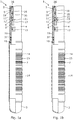
Fig. 1a shows anabandonment plug 1 for plug and abandonment of a well. Theabandonment plug 1 comprises afirst end part 3 being closed and forming a bottom of the plug, and asecond end part 4 being tubular and having agroove 5 in itsinner face 6. The second end part is closest to the top of the well. Theabandonment plug 1 further comprises anexpandable metal sleeve 7 arranged between the end parts, so that the expandable metal sleeve is the only element connecting the first end part and the second end part. Theend parts expandable metal sleeve 7, so that when a pressurised fluid is applied, the expandable metal sleeve is radially expanded to permanently deform and conform to the borehole wall or to a well tubular metal structure, thereby forming a plug therein. Theabandonment plug 1 furthermore comprises anexpansion unit 8 which is releasably connected within the second tubular end part. The expansion unit comprises at least one radiallyprojectable fastening element 9, aunit sleeve 10 and apiston 11 movable within the unit sleeve. Thepiston 11 moves between a first position, shown inFigs. 1a and 1b , in which thepiston 11 forces the radiallyprojectable fastening element 9 radially outwards in engagement with thegroove 5, and a second position, shown inFigs. 1c-1e , in which the piston is offset in relation to the radiallyprojectable fastening element 9, allowing the radially projectable fastening element to move radially inwards. - In
Fig. 1a , thepiston 11 has afirst piston part 16 and asecond piston part 17. Thefirst piston part 16 and thesecond piston part 17 are separate pistons capable of moving in relation to each other. After the ball is dropped as shown inFig. 1b , thesecond piston part 17 is able to move downwards, and the fluid under the ball expands theexpandable metal sleeve 7, as shown inFig. 1c . Theabandonment plug 1 further comprises a firstbreakable element 12 for maintaining thefirst piston part 16 of thepiston 11 in the first position, shown inFigs. 1a-1b , in relation to theunit sleeve 10 until thebreakable element 12 breaks at a predetermined force applied by a pressure difference between the annulus pressure acting on thefirst piston part 16 at theunit groove 19 and the expansion pressure inside the first piston part acting on a piston flange 44 below sealing element 37B, as shown inFig. 1c . By a further increase in pressure, thepiston 11 and theunit sleeve 10 move downwards releasing the unit sleeve by breaking a secondbreakable element 18, as shown inFig. 1d , and theexpansion unit 8 is retracted from the well as shown inFig. 1e . - As can be seen in
Fig. 1e , theexpandable metal sleeve 7 is mounted end to end to the first andsecond end parts expandable metal sleeve 7 is the only element connecting thefirst end part 3 and thesecond end part 4. The expansion unit has been released and pulled out and the plug is ready for being filled with cement to place cement above theplug 1. Theexpandable metal sleeve 7 hascircumferential projections 14 and a sealingelement 15 arranged between two projections to better seal against the borehole or within a well tubular metal structure. - By only relying on simple mechanical functions such as breaking a shear pin to expand the
abandonment plug 1 and then pull out theexpansion unit 8, no complex structure can get stuck and hinder the plug and abandonment. The plug left in the well is very simple but sufficient to hold the cement until it cures. When running the plug in, the fluid can easily pass the plug and no advanced flow-through is required since the cement is applied on top of the set plug. - The
abandonment plug 1 is typically connected to a workover pipe, drill pipe (a drill pipe string), coiled tubing or similar disconnectable tubing in order to provide pressurised fluid from surface to expand theabandonment plug 1 and disconnect when the plug has been set. In another embodiment, theabandonment plug 1 is connected to a wireline tool having a pump for providing the pressurised fluid. - The
piston 11 is tubular provided by abore 36 and thus has a very simple design. The piston ofFigs. 1a-1d has afirst piston part 16 and asecond piston part 17 which are movable in relation to each other. Thefirst piston part 16 is tubular so that the ball can flow past, and the second piston part is bore-less so that theball 22 can seat in aball seat 21 in thesecond piston part 17 and the second piston part functions as thepiston 11 enabling expansion of theexpandable metal sleeve 7. - The
abandonment plug 1 further comprises the secondbreakable element 18 between theunit sleeve 10 and thesecond end part 4 as a safety precaution for maintaining the unit sleeve in the first position in relation to the second end part during expansion of the expandable metal sleeve until the secondbreakable element 18 breaks at a predetermined force. However, the second breakable element is easy to break by applying a downward force on theunit sleeve 10, e.g. by increasing the pressure, and theexpansion unit 8 can thus always be easily retracted. Theunit sleeve 10 ofFig. 1a has aunit groove 19 in which the radiallyprojectable fastening element 9 is arranged. Theunit sleeve 10 further comprises sealingelements 37 arranged between theunit sleeve 10 and thesecond end part 4. - The
abandonment plug 1 ofFigs. 2a-2e has anopening 23 in thesecond end part 4 for receiving a wiper dart 24 (or a ball) to close the second end part. By having anopening 23 in the second end part, cement can be injected below theplug 1 before theexpandable metal sleeve 7 is expanded and the plug set. After the cement has been applied through theopening 23, awiper dart 24 is dropped and seats in thesecond end part 4, as shown inFig. 2b , closing thesecond end part 4. Subsequently, cement can be applied through a drill pipe string of drill pipe connected to the plug, and theexpandable metal sleeve 7 is expanded as shown inFig. 2c . In this step, the firstbreakable element 12 is broken by thepiston 11 moving slightly downwards, so that the radiallyprojectable fastening element 9 is free to move radially inwards. This is due to the same pressure difference over thefirst piston part 16, as described in relation toFig. 1a-1e . By continuing the pressure increase, thepiston 11 and theunit sleeve 10 is moved downwards, breaking also the secondbreakable element 18, and the drill pipe/drill pipe string can be retracted together with theexpansion unit 8, as shown inFig. 2e , while pumping cement down the drill pipe and the expansion unit which then is applied above the plug if requested by the operator. Theplug 1 can thus be set in the middle of a cemented zone to contribute to the curing process in the intended position as thisplug 1 can be applied with cement under, in and above the plug. InFigs. 2a-2d , thepiston 11 is one part only moving from the first position to the second position. - In
Fig. 3a , theunit sleeve 10 has a through-bore 26 in which thepiston 11 slides as inFigs. 1a-1d andFigs. 2a-2d . Theunit sleeve 10 of theabandonment plug 1 ofFigs. 3a-3d is connected to a housing of a stroking tool 32 (shown inFig. 5a ). The stroking tool has a stroking shaft which in a first downward stroke pushes thesecond piston part 17 downwards to expand theexpandable metal sleeve 7 by the enclosed fluid below thesecond piston part 17. In a second stroke, the stroking tool engages the grooves 38 (shown inFig. 3a ) in thetubular piston 11 and moves thefirst piston part 16 downwards breakingbreakable element 12. In another embodiment the stroking tool may provide a pressurised fluid to move thesecond piston part 17, as shown inFig. 3b , in order to expand theexpandable metal sleeve 7. The stroking tool then provides a further downward stroke to displace thepiston 11 and theunit sleeve 10 downwards, breaking the second breakable element, i.e. ashear pin 18, and releasing theexpansion unit 8 from thesecond end part 4, as shown inFig. 3c , and the tool is retracted, as shown inFig. 3d . - Sealing means 37 is provided in different places, as shown in
Figs. 1a-3d , for ensuring a sufficient seal between moving parts of theabandonment plug 1. As shown inFig. 3d , theexpandable metal sleeve 7 is mounted by means ofconnection parts 41 to anend 42 of thefirst end part 3 and to anend 43 of thesecond end part 4. Thus, the connection parts overlap theends expandable metal sleeve 7 end to end to the first andsecond end parts - In
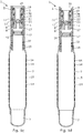
Figs. 4a-4c , a plug andabandonment system 100 is shown in awell 2 comprising the abandonment plug and acement supply 31 for supplying cement above the plug, below the plug and/or in the plug depending on what plug solution is chosen. The plug andabandonment system 100 is arranged in aborehole 102 by means ofdrill pipe 25 or similar disconnectable tubing from a top 103 of the well. - In
Figs. 5a-5b , the plug andabandonment system 100 is shown in awell 2 and comprises a strokingtool 32 connected to the expansion unit for providing an axial force for expanding theexpandable metal sleeve 7, as shown inFig. 5b , where theexpansion unit 8 has been withdrawn, andcement 35 is applied above theplug 1. - A stroking
tool 32 is a tool providing an axial force. The stroking tool comprises an electrical motor for driving a pump. The pump pumps fluid into a piston housing to move a piston acting therein. The piston is arranged on the stroker shaft. The pump may pump fluid into the piston housing on one side and simultaneously suck fluid out on the other side of the piston. - By fluid or well fluid is meant any kind of fluid that may be present in oil or gas wells downhole, such as natural gas, oil, oil mud, crude oil, water, etc. By gas is meant any kind of gas composition present in a well, completion, or open hole, and by oil is meant any kind of oil composition, such as crude oil, an oil-containing fluid, etc. Gas, oil, and water fluids may thus all comprise other elements or substances than gas, oil, and/or water, respectively.
- By an annular barrier is meant an annular barrier comprising a tubular metal part mounted as part of the well tubular metal structure and an expandable metal sleeve surrounding and connected to the tubular part defining an annular barrier space.
- By a casing or a well tubular metal structure is meant any kind of pipe, tubing, tubular, liner, string etc. used downhole in relation to oil or natural gas production.
- In the event that the tool is not submergible all the way into the casing, a downhole tractor can be used to push the tool all the way into position in the well. The downhole tractor may have projectable arms having wheels, wherein the wheels contact the inner surface of the casing for propelling the tractor and the tool forward in the casing. A downhole tractor is any kind of driving tool capable of pushing or pulling tools in a well downhole, such as a Well Tractor®.
- Although the invention has been described in the above in connection with preferred embodiments of the invention, it will be evident for a person skilled in the art that several modifications are conceivable without departing from the invention as defined by the following claims.
Claims (15)
- Abandonment plug (1) for plug and abandonment of a well (2), said abandonment plug comprising:- a first end part (3) being closable or closed,- a second end part (4) being tubular and having a groove (5) in an inner face (6),- an expandable metal sleeve (7) arranged between the end parts, the end parts being more rigid than the expandable metal sleeve, and- an expansion unit (8) releasably connected to the second tubular end part, the expansion unit comprising:- at least one radially projectable fastening element (9),- a unit sleeve (10), and- a piston (11) movable in the unit sleeve for, in a first position, forcing the radially projectable fastening element and, in a second position, being offset in relation to the radially projectable fastening element, allowing the radially projectable fastening element to move radially inwards.
- Abandonment plug according to claim 1, further comprising a first breakable element (12) for maintaining the piston in the first position in relation to the unit sleeve until the breakable element breaks at a predetermined force.
- Abandonment plug according to claim 1 or 2, wherein the expandable metal sleeve is mounted end to end to the first and second end parts.
- Abandonment plug according to any of the preceding claims, wherein the piston is tubular.
- Abandonment plug according to any of the preceding claims 1-3, wherein the piston has a first piston part (16) and a second piston part (17) which are movable in relation to each other.
- Abandonment plug according to claim 5, wherein the first piston part is tubular and the second part is bore-less.
- Abandonment plug according to any of the preceding claims, further comprising a second breakable element (18) between the unit sleeve and the second end part.
- Abandonment plug according to any of the preceding claims, wherein the unit sleeve has a unit groove (19) in which the radially projectable fastening element is arranged.
- Abandonment plug according to any of the preceding claims, wherein the piston has a ball seat (21) for receiving a ball (22) dropped into the well.
- Abandonment plug according to any of the preceding claims, wherein the second end part has an opening (23) for receiving a wiper dart (24) or ball to close the second end part.
- Abandonment plug according to any of the preceding claims, wherein the plug is connected to a workover pipe, drill pipe (25), coiled tubing or similar disconnectable tubing.
- Abandonment plug according to any of the preceding claims, wherein the unit sleeve has a through-bore (26) in which the piston slides.
- Plug and abandonment system comprising the abandonment plug according to any of the preceding claims and a cement supply (31) for supplying cement above the plug, below the plug and/or in the plug.
- Plug and abandonment system according to claim 13, further comprising a stroking tool (32) connected to the expansion unit for providing an axial force for expanding the expandable metal sleeve.
- Plug and abandonment system according to claim 13, further comprising diconnectable tubing (25) connecting the cement supply with the plug.
Priority Applications (10)
| Application Number | Priority Date | Filing Date | Title |
|---|---|---|---|
| EP17206810.8A EP3498968A1 (en) | 2017-12-12 | 2017-12-12 | Abandonment plug and plug and abandonment system |
| PCT/EP2018/084275 WO2019115491A1 (en) | 2017-12-12 | 2018-12-11 | Abandonment plug and plug and abandonment system |
| CA3084273A CA3084273A1 (en) | 2017-12-12 | 2018-12-11 | Abandonment plug and plug and abandonment system |
| BR112020010108-7A BR112020010108B1 (en) | 2017-12-12 | 2018-12-11 | ABANDONMENT BUFFER AND ABANDONMENT BUFFER AND SYSTEM |
| US16/215,995 US11220879B2 (en) | 2017-12-12 | 2018-12-11 | Plug and plug and abandonment system |
| AU2018385362A AU2018385362B2 (en) | 2017-12-12 | 2018-12-11 | Abandonment plug and plug and abandonment system |
| CN201880077614.6A CN111417765A (en) | 2017-12-12 | 2018-12-11 | Abandonment well plug and jam and abandonment system |
| RU2020121362A RU2799020C2 (en) | 2017-12-12 | 2018-12-11 | Well abandonment plug and well plugging and abandonment system |
| EP18826979.9A EP3724442B1 (en) | 2017-12-12 | 2018-12-11 | Abandonment plug and plug and abandonment system |
| MX2020005469A MX2020005469A (en) | 2017-12-12 | 2018-12-11 | Abandonment plug and plug and abandonment system. |
Applications Claiming Priority (1)
| Application Number | Priority Date | Filing Date | Title |
|---|---|---|---|
| EP17206810.8A EP3498968A1 (en) | 2017-12-12 | 2017-12-12 | Abandonment plug and plug and abandonment system |
Publications (1)
| Publication Number | Publication Date |
|---|---|
| EP3498968A1 true EP3498968A1 (en) | 2019-06-19 |
Family
ID=60673202
Family Applications (1)
| Application Number | Title | Priority Date | Filing Date |
|---|---|---|---|
| EP17206810.8A Withdrawn EP3498968A1 (en) | 2017-12-12 | 2017-12-12 | Abandonment plug and plug and abandonment system |
Country Status (1)
| Country | Link |
|---|---|
| EP (1) | EP3498968A1 (en) |
Cited By (1)
| Publication number | Priority date | Publication date | Assignee | Title |
|---|---|---|---|---|
| WO2022119445A1 (en) * | 2020-12-03 | 2022-06-09 | Brigantyne B.V. | Method and system for closing a well |
Citations (5)
| Publication number | Priority date | Publication date | Assignee | Title |
|---|---|---|---|---|
| US3053322A (en) * | 1960-01-28 | 1962-09-11 | Albert K Kline | Oil well cementing shoe |
| US20040069485A1 (en) * | 2002-10-09 | 2004-04-15 | Ringgengberg Paul D. | Downhole sealing tools and method of use |
| EP2565365A1 (en) * | 2011-08-31 | 2013-03-06 | Welltec A/S | Disconnecting tool |
| EP2570588A1 (en) * | 2011-09-13 | 2013-03-20 | Welltec A/S | Annular barrier with axial force mechanism |
| EP2947259A1 (en) * | 2014-05-19 | 2015-11-25 | Welltec A/S | Downhole string for drilling through a low pressure zone |
-
2017
- 2017-12-12 EP EP17206810.8A patent/EP3498968A1/en not_active Withdrawn
Patent Citations (5)
| Publication number | Priority date | Publication date | Assignee | Title |
|---|---|---|---|---|
| US3053322A (en) * | 1960-01-28 | 1962-09-11 | Albert K Kline | Oil well cementing shoe |
| US20040069485A1 (en) * | 2002-10-09 | 2004-04-15 | Ringgengberg Paul D. | Downhole sealing tools and method of use |
| EP2565365A1 (en) * | 2011-08-31 | 2013-03-06 | Welltec A/S | Disconnecting tool |
| EP2570588A1 (en) * | 2011-09-13 | 2013-03-20 | Welltec A/S | Annular barrier with axial force mechanism |
| EP2947259A1 (en) * | 2014-05-19 | 2015-11-25 | Welltec A/S | Downhole string for drilling through a low pressure zone |
Cited By (2)
| Publication number | Priority date | Publication date | Assignee | Title |
|---|---|---|---|---|
| WO2022119445A1 (en) * | 2020-12-03 | 2022-06-09 | Brigantyne B.V. | Method and system for closing a well |
| NL2027036B1 (en) * | 2020-12-03 | 2022-07-06 | Brigantyne B V | Method and system for closing a well |
Similar Documents
| Publication | Publication Date | Title |
|---|---|---|
| EP3724442B1 (en) | Abandonment plug and plug and abandonment system | |
| US9970248B2 (en) | Downhole system and method for fastening upper and lower casings via expandable metal sleeve | |
| CN107923229B (en) | Sealing position of well bore | |
| AU2019258528B2 (en) | Workover tool string | |
| AU2019250350B2 (en) | Downhole straddle system | |
| CN107849906B (en) | Well centralizer | |
| US11142976B2 (en) | Positioning downhole-type tools | |
| EP3498968A1 (en) | Abandonment plug and plug and abandonment system | |
| EP4063610A1 (en) | Wireline plug system | |
| EP3553273A1 (en) | Downhole straddle system | |
| EP3495602A1 (en) | Downhole repairing system | |
| CA2901905A1 (en) | Plug and perforate using casing profiles | |
| RU2799020C2 (en) | Well abandonment plug and well plugging and abandonment system |
Legal Events
| Date | Code | Title | Description |
|---|---|---|---|
| PUAI | Public reference made under article 153(3) epc to a published international application that has entered the european phase |
Free format text: ORIGINAL CODE: 0009012 |
|
| AK | Designated contracting states |
Kind code of ref document: A1 Designated state(s): AL AT BE BG CH CY CZ DE DK EE ES FI FR GB GR HR HU IE IS IT LI LT LU LV MC MK MT NL NO PL PT RO RS SE SI SK SM TR |
|
| AX | Request for extension of the european patent |
Extension state: BA ME |
|
| RAP1 | Party data changed (applicant data changed or rights of an application transferred) |
Owner name: WELLTEC OILFIELD SOLUTIONS AG |
|
| STAA | Information on the status of an ep patent application or granted ep patent |
Free format text: STATUS: THE APPLICATION IS DEEMED TO BE WITHDRAWN |
|
| 18D | Application deemed to be withdrawn |
Effective date: 20191220 |